
Submitted:
18 October 2023
Posted:
18 October 2023
You are already at the latest version
Abstract
This study examined the impact of Vibration-Assisted Drilling (VAD) on hole quality and residual stress in Ti-6Al-4V ELI material. Ti-6Al-4V ELI possesses excellent mechanical properties but presents challenges in machining, including chip evacuation, burr formation, and elevated cutting temperatures. VAD, particularly Low-Frequency Vibration-Assisted Drilling (LF-VAD), has been explored as a potential solution to address these issues. The research com-pares LF-VAD with conventional drilling (CD) under various cutting and cooling conditions. LF-VAD exhibits higher maximum cutting forces under specific conditions, which result in accel-erated tool wear. However, it also demonstrates lower RMS (Root Mean Square) forces com-pared to CD, offering better control over chip formation, reduced burr formation, and improved surface roughness within the hole. Furthermore, LF-VAD generates greater compressive residual stresses on the hole's inner surface compared to CD, suggesting enhanced fatigue performance. These findings indicate that LF-VAD holds promise for improving hole quality, fatigue life, and overall component durability in Ti-6Al-4V machining applications.
Keywords:
Ti-6Al-4V ELI
; machining
; low-frequency vibration-assisted drilling
; residual stress
1. Introduction
Titanium alloys are renowned for their exceptional mechanical properties and are characterized by a high strength-to-weight ratio, inherent corrosion resistance, and outstanding fatigue and creep resistance[1,2]. These distinctive attributes have rendered titanium highly coveted in various high-value sectors, notably in aerospace and related industries[3]. Within this class of alloys, Ti-6Al-4V extra low interstitial (ELI) stands out for its notable suppression of impurities, resulting in enhanced ductility and fracture toughness compared with the conventional Ti-6Al-4V[4,5]. Notably, it maintains resilience even at extremely low temperatures, rendering it indispensable in cryogenic applications. Furthermore, this alloy finds extensive applications in diverse fields, including biomedical implants, aerospace components, and offshore equipment[6,7,8].
Despite these advantages, the machining of titanium-based alloys is recognized as a formidable challenge in the manufacturing industry. Common issues encountered include difficulties in chip removal, elevated cutting temperatures leading to tool welding, accelerated tool wear due to the material’s low thermal conductivity, challenges in burr removal, and the material’s high chemical affinity with tools[9,10,11,12]. These issues are exacerbated during drilling due to the enclosed machining environment, hindering heat and chip evacuation and resulting in elevated cutting temperatures and diminished surface quality[13]. In particular, problematic chip evacuation generally leads to the formation of long, continuous chips that adversely impact surface quality, rendering drilling titanium alloys a complex task in real industrial settings[14]. To improve efficiency and productivity in machining titanium alloy holes, ongoing investigations explore various methods, including tool coatings, enhanced cooling processes, and innovative tool designs. Vibration-assisted drilling (VAD) has emerged as a promising trend for addressing these challenges.
VAD induces chip segmentation through axial tool oscillation. Among VAD techniques, those with relatively high amplitude and frequencies below 1000 Hz are defined as low-frequency vibration assisted drilling (LF-VAD)[15,16,17]. This technology allows for control over chip generation and removal mechanisms. Research into chip-breaking phenomena in LF-VAD has been conducted for materials such as titanium alloys[18,19], titanium-CFRP composites[20,21,22], and aluminum[23], with both numerical and experimental studies exploring these phenomena.
However, existing research results mainly occupy cases where the hole depth is less than 2 × D (hole diameter), and investigations into deeper holes are very limited [15,17,18,19,22,24,25,26,27,28]. Furthermore, previous research has mainly focused on dry machining and minimal quantity lubrication (MQL) for analyzing chip evacuation mechanisms. When deeper hole machining is required in the context of structural and mechanical components, dry or MQL cooling conditions are ineffective due to heat dissipation issues[29], and thus, stronger cooling conditions are required. Additional research is needed to understand the impact of LFVAD on such processing. Therefore, in this study, using Ti-6Al-4V ELI material, machining experiments are conducted at depths exceeding 2 × D at various cooling conditions and cutting speeds. The research aims to provide suitable machining parameters for LF-VAD by analyzing cutting forces, tool wear, hole surface roughness, burr size, and residual stresses under different machining conditions.
2. Materials and Methods
In this investigation, we employed the prevalent wet cooling method to examine variations in internal coolant pressure and cutting speed. To explore diverse conditions, we utilized two cutting fluid pressure levels (10 bar and 40 bar) along with three cutting speeds. These speeds encompassed the standard cutting speed of 40 m/s, commonly applied for stable cutting in industrial settings. Additionally, conditions of 80 m/s and 120 m/s were considered to assess distinctions in cutting behavior between LF-VAD machining in extreme environments and conventional drilling (CD). The selection of these conditions took into account the limitations of the LF-VAD holder (maximum RPM: 6500; maximum internal coolant pressure: 45 bar).
Figure 1 is a schematic representation of the experimental setup. For CD machining, a 130 mm shrink fit holder (HAIMER) was employed, whereas MITIS’s PM4225 holder was used for LF-VAD machining. The holder utilized in vibration-assisted drilling features a cam structure with a sinusoidal shape, generating 2.5 vibrations per revolution and an amplitude of 125 µm. The experiments were executed using a 4-axis DIXI JIG1200 boring machine center. All machining operations were conducted with a 9139AA dynamometer (KISTLER) affixed to the jig base, capable of measuring cutting forces in the Z-axis direction, aligning with the drilling direction per the equipment's reference. Collected data were recorded using a 5617A80 amplifier (KISTLER). In drilling operations, where cutting loads predominantly act in the tool’s direction, cutting thrust in the drilling direction (Z-axis) was measured. Forces recorded in the X and Y-axis directions were not considered in the analysis.
The utilized tool possessed a standard diameter of 6 mm, a common size in the aerospace industry. Machining employed a TiAlN-coated WC drill (YG-1, DREAM DRILL INOX DH452060). The Ti-6Al-4V ELI (Grade 23) titanium alloy blocks, with dimensions of 100 mm (W) × 100 mm (L) × 30 mm (H), served as the machining substrate. Table 1 provides details on the drill’s specifications, while Table 2 outlines the physical and mechanical properties of the titanium alloy. For each set of conditions, 20 holes were machined, and chip collection occurred after the first and last holes were completed. The collected chips for analysis underwent resin mounting, grinding up to 2000 grit, and subsequent polishing down to 1 µm. Following these steps, etching with Kroll’s reagent for 10 s was conducted, followed by chip morphology and phase analysis. A few finished samples were cut at the hole center using electrical discharge machining (SODICK, SL400G) to measure surface roughness (SV-2100, Mitutoyo) and residual stresses (µ-X360s, PULSTEC) within the hole. Surface roughness, assessed in terms of Ra values for an overall analysis of the hole’s surface finish, was measured at different areas with 5 mm intervals, totaling five measurements. The average value of these measurements was calculated subsequently. Residual stresses were measured using X-ray, with a beam size set to 0.5 mm to minimize interference with the inner surface curvature of the hole.
3. Results
3.1. Cutting Force
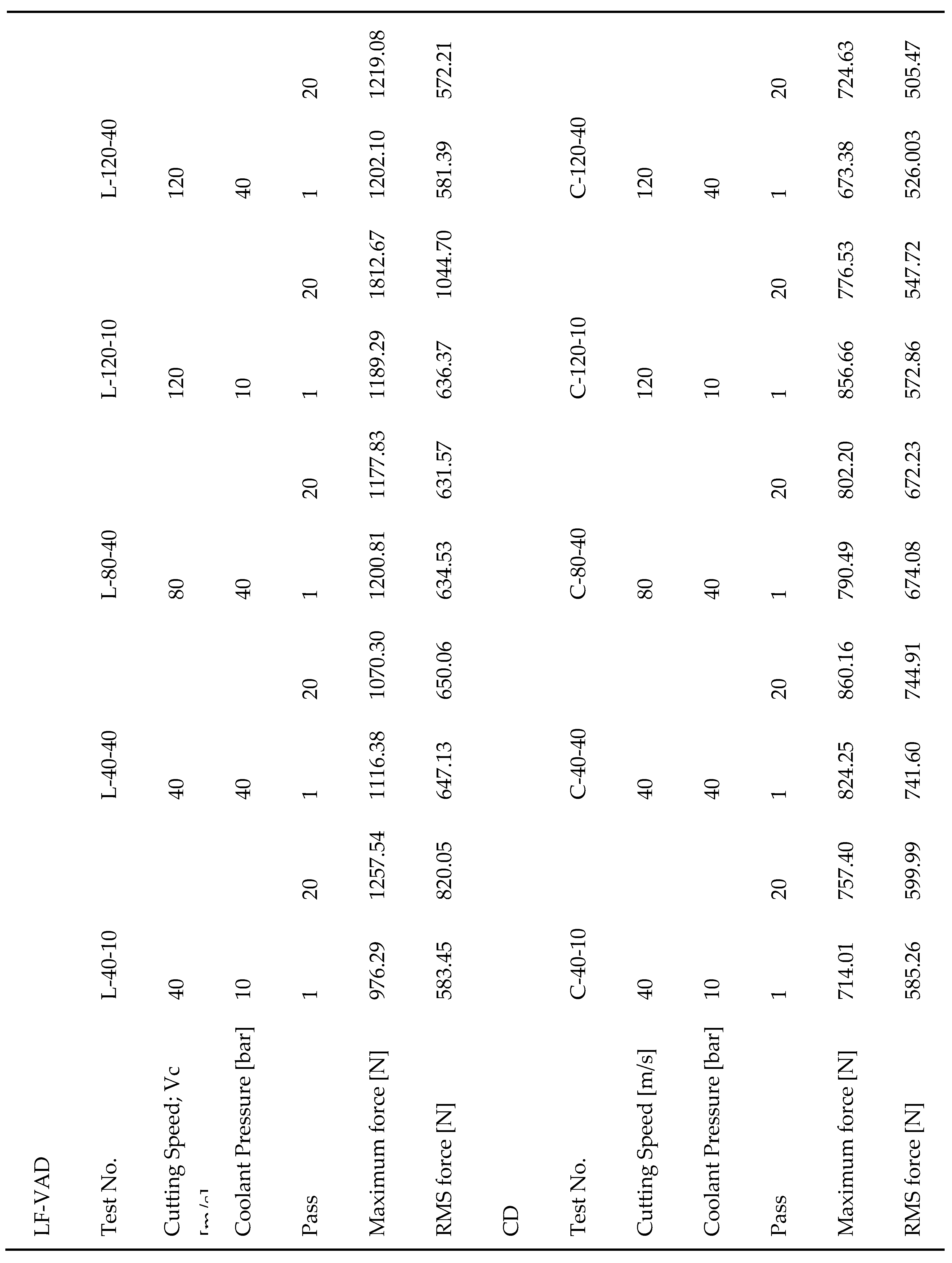
Differences between LF-VAD and CD are initially compared through cutting forces, as presented in Table 3. This table shows the maximum and root mean square (RMS) thrust force values for various drilling methods and cutting conditions, along with labels for the experimental conditions. Figure 2 illustrates thrust force graphs for the L-80-40 and C-80-40 conditions, providing a visual representation of typical behavioral distinctions between the two cutting methods. As evident in the graph, the cutting force in LF-VAD exhibits sinusoidal variation over time. To facilitate comparisons based on periodically changing values, RMS values were utilized for analysis instead of the mean value. Each RMS value was computed from a consistent intermediate segment of force variation (Vc40: 5 s, Vc80: 4 s, and Vc120: 2.5 s). This study conducted experiments under various conditions, encompassing different machining methods (CD and LF-VAD), diverse cutting speeds (40 m/s, 80 m/s, and 120 m/s), and varying cutting fluid pressures (10 bar and 40 bar). To systematically analyze these conditions, the cutting force analysis was divided into 1) Maximum force and 2) RMS force analysis. The RMS force analysis section was further subdivided into 1) Cutting force analysis based on cutting fluid pressure conditions and 2) Cutting force analysis based on cutting speed.
Concerning maximum thrust force, LF-VAD conditions consistently recorded higher forces compared with CD, ranging from a decrease of 24% (L-40-40, 20 passes) to an increase of 133% (L-120-10, 20 passes). This phenomenon is attributed to the distinctive characteristics of the LF-VAD machining method. In contrast to the CD process, where a uniform depth (0.08 mm/rev in this study) is achieved at regular rotations, LF-VAD demonstrates continuously changing feed rates due to the sinusoidal vibration in the axial direction. Chips, which are cut to a consistent thickness in the CD process, become segmented in the LF-VAD process due to the applied vibration, inevitably resulting in larger maximum forces[18]. This mechanism is schematically represented in Figure 2 and 3, and the schematic diagram of the chip generation mechanism in Figure 2 is based on the research results[22] of Haojun Yang et al.
Maximum force represents the peak force applied to the tool at a specific moment, while RMS force indicates the continuous force acting on the tool during machining. In contrast to consistently higher maximum forces exhibited by LF-VAD compared to CD across all conditions, RMS values showed variations based on the cutting conditions.
Firstly, RMS values during hole machining varied depending on the cutting fluid pressure (10 bar and 40 bar). In CD, at a cutting speed of 40 m/s and over 20 passes, an increase in cutting fluid pressure resulted in a 24% increase in RMS force. However, at a cutting speed of 120 m/s, an increase in cutting fluid pressure led to a decrease of approximately 7% in RMS force. This highlights that higher cutting fluid pressure does not necessarily lead to improved machinability in CD, emphasizing the need to adjust cutting fluid pressure based on cutting speed. CD exhibited a relatively stable trend in cutting force with increasing passes from 1 to 20 passes, irrespective of cutting fluid pressure. In LF-VAD conditions, changes in cutting fluid pressure led to a more pronounced impact. For instance, machining at a cutting speed of 120 m/s with a pressure of 10 bar (L-120-10) resulted in an increase in force from 636.37 N at 1 pass to 1044.70 N at 20 passes. Similarly, at a cutting speed of 40 m/s (L-40-10), forces measured were 578.45 N and 820.05 N at 1 pass and 20 passes, respectively. In contrast, under LF-VAD conditions with the same LF-VAD parameters but a cutting fluid pressure of 40 bar (L-40-40, L-80-40, and L-120-40), a minimal change in the cutting force was observed with increasing passes. This indicates that when the cutting fluid pressure is low at 10 bar, the increase in cutting force is significantly higher compared with machining at 40 bar. This observed phenomenon in LF-VAD machining conditions can be attributed to temperature during cutting. Low cutting fluid pressure (10 bar) in LF-VAD machining may not efficiently expel segmented chips, leading to increased cutting resistance. Additionally, the LF-VAD process involving machining chips at deeper feed rates with vibrations during machining presents cooling challenges compared to CD. Elevated cutting temperatures accelerate adhesion wear due to the high chemical affinity between titanium and the tool, promoting tool wear. Moreover, if these conditions persist and maintain high temperatures, they enhance material ductility, rendering it difficult for chips to segmentize. This hinders chip evacuation and increases cutting resistance, resulting in rapid tool wear.
Secondly, RMS force trends during hole machining varied with the cutting speed (40 m/s, 80 m/s, and 120 m/s). In CD, analyzing RMS force based on 1 pass revealed an order of cutting forces as follows: C-120-40 (526.00 N), C-120-10 (572.86 N), C-40-10 (585.26 N), C-80-40 (674.08 N), and C-40-40 (741.60 N), demonstrating an overall increase in the cutting force as the cutting speed decreases. This aligns with previous research indicating that as cutting speed increases (higher RPM and higher feed), cutting thrust force decreases. However, the trends exhibited variations according to the combination of cutting fluid pressure and cutting speed, underscoring the need for customized cutting conditions in CD machining situations. Under CD conditions, cutting forces from 1 pass to 20 passes exhibited a consistent trend across all conditions, with no significant increase in cutting force as the number of passes increased. Under LF-VAD conditions, similar to CD, the lowest cutting force was observed in the condition with the highest cutting speed, L-120-40. When comparing cutting forces for conditions machined with 40 bar of cutting fluid pressure (based on 1 pass), the order of cutting forces was L-120-40 (581.39 N), L-80-40 (634.53 N), and L-40-40 (647.13 N). Higher cutting speeds corresponded to lower cutting forces.
3.2. Chip Extraction and Chip Formation
The chip shapes collected from the LF-VAD and CD machining processes after 20 passes are depicted in Figure 4. In LF-VAD, axial vibration is introduced to the axial feeding movement of the CD process. This sinusoidal vibration effectively segments the chips, facilitating their crushing and subsequent removal.
In this study, the vibration device (PM 4225, MITIS) utilized for LF-VAD machining incorporates a mechanical cam structure, resulting in a fixed vibration frequency of 2.5 times per one rotation. Consistent with previous research findings, machining was conducted at a feed rate of 0.08 mm/rev, recognized as the most effective for chip segmentation and overall machining efficiency[26]. Given the fixed nature of the vibration frequency and feed rate per revolution, substantial variations in the chip formation mechanism due to machining conditions in LF-VAD are not anticipated. Consequently, no significant difference in the shape of the chips was observed across conditions machined at cutting speeds ranging from 40 m/s to 120 m/s.
Nevertheless, variations in cooling conditions, such as cutting fluid pressure and cutting speed, introduce slight differences in the shape of chips discharged in LF-VAD. Firstly, in processes with a cutting fluid pressure set to 10 bar (Figure 4f and i), chip segmentation occurred normally; however, due to insufficient cutting fluid pressure, elevated temperature, and adhesion wear, complete fragmentation did not occur. While numerical analysis is impeded by constraints in the machining process and chip collection (attributed to the cutting fluid), an observed phenomenon is the occasional inadequate cutting of chips, causing them to stick together more frequently. Conversely, in processes with a high cutting fluid pressure of 40 bar (Figure 4g, h, and j), chip segmentation and fragmentation occurred smoothly. This suggests that low cutting fluid pressure in LF-VAD machining hampers chip segmentation, potentially leading to chip clogging in hole machining processes. This underscores the importance of maintaining an appropriate cutting fluid pressure in LF-VAD machining.
The impact of low coolant pressure on temperature variation in the LF-VAD process is elucidated through the analysis of chip phase morphology in Figure 5, specifically examining the L-120-10 and L-120-40 conditions. In the LF-VAD process, chips segment; however, under the L-120-10 condition where perfect separation is not achieved, the grain size is notably larger compared with that under the L-120-40 condition. The elevated temperature during material cutting is subsequently reduced through internal coolant and chip expulsion. Under the L-120-40 condition, efficient chip separation and expulsion, facilitated by sufficient coolant pressure, result in a rapid temperature decrease. The elevated temperature causes chips with larger grain sizes to rapidly cool down, transforming into smaller-grain chips. Conversely, under the L-120-10 condition where adequate heat dissipation is lacking, chips with larger grain sizes persist due to a relatively slow temperature decrease. This interpretation explains the observed phenomenon of chip adhesion, underscoring the critical role of an appropriate cooling mechanism.
In contrast, in the CD process, where there are no physical devices such as LF-VAD to induce chip segmentation, deviations tend to become relatively larger with changes in the cutting speed. Titanium chips in the CD process exhibit features such as sawtooth edges, localized shearing, discontinuity, periodicity, and a splintered form, resulting in shapes such as spiral-cone shapes or folded ribbons.
When comparing chip morphology at the same cutting fluid pressure of 40 bar and varying cutting speeds in the CD process (Figure 4 b, c, and e), at a cutting speed of 40 m/s, a stable spiral-cone shape is observed with certain instances of folded ribbon chips (Figure 4 b). As the cutting speed increases to 80 m/s, a transitional phase is noted where the spiral-cone-shaped chips are not smoothly ejected but rather compressed into folded long chips (Figure 4 c). At a cutting speed of 120 m/s, a fully formed folded long ribbon chip is observed (Figure 4 d). The phenomenon of folded ribbon chip formation intensifies as chip ejection resistance increases, particularly when the cutting fluid pressure is reduced to 10 bar. Unlike the stable formation of spiral chips observed under the C-40-40 condition, the C-40-10 condition exhibits the formation of folded ribbon chips as the cutting fluid pressure decreases. Similarly, when experimenting with higher cutting speeds and lower cutting fluid pressure, as under the C-120-10 condition, even longer folded ribbon chips are generated.
As chip ejection resistance increases, the formation of folded long ribbon chips can lead to several issues during drilling, including increased cutting force, accelerated tool wear, and a deterioration in hole quality. Even the ideal chip morphology, i.e., the spiral-cone shape obtained through the CD process can be affected by scratches generated during chip transport from the cutting region to the exit, impacting the surface quality around the hole. To address these issues, various cutting methods and specialized tool shapes have traditionally been employed. Based on the results regarding chip morphology, LF-VAD offers clear advantages compared with CD. In LF-VAD machining, although complete separation of segmented chips may not occur as the cutting speed increases, the chip segmentation process is effectively managed through a mechanical mechanism, and optimization can be achieved by adjusting the cutting speed.
3.3. Tool Wear
Here trends in tool wear are analyzed after machining the Ti-6Al-4V ELI material with a thickness of 30 mm for 20 passes. Tool wear can manifest in various forms, including chisel edge wear, flank wear, and chipping wear. Figure 6 illustrates the wear on the chisel edge area for each cutting condition. The analysis reveals clear differences in chisel edge wear based on the machining method (CD and LF-VAD) and machining conditions (coolant pressure and cutting speed). However, unusual trends are scarcely observed in flute wear, chipping, crater wear, and other wear types.
Comparing tool wear in the chisel edge area between LF-VAD and CD processes conducted at the same cutting speed and cutting fluid pressure, it becomes evident that tool wear is significantly higher in LF-VAD for all conditions. In LF-VAD processing, tool wear in this area is attributed to the strong compressive forces applied periodically due to the axial vibration, a characteristic of the LF-VAD process. During this process, the high chemical affinity between the titanium alloy and the tool, coupled with the temperature increase resulting from compression, leads to increased adhesion between the material and the tool, promoting wear[21]. This wear is even more pronounced under conditions with a coolant pressure of 10 bar.
In conclusion, from the perspective of tool wear, LF-VAD performs less favorably than CD. While LF-VAD effectively induces chip removal, reducing cutting resistance, and can reduce cutting forces (RMS) with appropriate cooling conditions, its unique cutting method exerts more force on the tool, thereby accelerating wear.
3.4. Burr Height and Surface Quality
The surface quality of a hole is defined by parameters such as burr formation and surface roughness. Among these, burr formation is a common issue during the drilling process and occurs due to the plastic deformation of the material. As the tool approaches the hole’s exit, the material undergoes plastic deformation. If it cannot withstand this deformation, it can lead to crack initiation at the hole’s edge or extrusion of material outward, resulting in burr formation. Typically, burrs are formed at the entrance and exit of the hole, significantly affecting dimensional accuracy. While entrance burrs are usually small and can be easily removed during the chamfering process, exit burrs pose a more significant challenge in terms of removal. Residual exit burrs create stress concentrations, serving as initiation points for fatigue failure and corrosion, ultimately reducing the lifespan of mechanical components. Moreover, the process of removing these burrs contributes to manufacturing costs that cannot be overlooked. This, in turn, increases machining time and reduces production efficiency. Considering the impact on product quality, lifespan, and production costs, it is crucial to implement measures to suppress burr formation during the machining process.
Figure 7 illustrates a graph depicting the variation in burr size based on cutting speed and machining processes. In the preceding analysis, LF-VAD processes with low cutting fluid pressure (10 bar) exhibited a sharp increase in cutting forces and wear levels as the number of passes increased. Therefore, these conditions were excluded for the analysis determining hole quality. Burr analysis involved measuring the length at two points for each condition and calculating the average value for analysis. The results indicate that LF-VAD conditions recorded burr sizes equal to or smaller than CD conditions under all cutting speed conditions. Under the L-120-40 condition, the average burr size was 109.5 µm, approximately 40% smaller than the 183 µm measured under the C-120-40 condition. Similarly, the average burr size under the L-40-40 condition was 79 µm, approximately 44% smaller than the 141.5 µm measured under the C-40-40 condition. At a cutting speed of 80 m/s, almost similar burr sizes were observed, with the L-80-40 condition showing slightly smaller burrs. This indicates that LF-VAD is effective in suppressing burr formation in the drilling of Ti-6Al-4V ELI material for most conditions. However, when comparing LF-VAD processes alone, it is evident that burr size increases linearly with increasing cutting speed. This trend is attributed to the machining temperature. High cutting speeds elevate the machining temperature, accumulating a significant amount of heat in the material that increases its ductility. Increased ductility enhances material flowability, allowing machining with lower cutting forces. However, at the exit point, the tool pushes out the more ductile material, affecting burr size significantly. Through this comparison, it is confirmed that LF-VAD is a superior machining method in terms of burr size. Additionally, this burr analysis also confirms that LF-VAD machining operates at lower temperatures compared with CD machining.
Surface roughness is another important parameter in determining hole quality, and Figure 8 presents the variation in surface roughness with cutting speed and machining process. The graph illustrates that holes machined by the LF-VAD process exhibit lower surface roughness (L-40-40, L-80-40). This is because LF-VAD machining effectively suppresses the scratching of the hole’s interior surface during the exit of chips along the tool's flute, unlike in the CD process where continuous chips are expelled, causing scratching. However, for conditions processed at a cutting speed of 120 m/s, it can be observed that the surface roughness for LF-VAD-machined conditions is slightly higher. This can be attributed to the earlier chip analysis that showed that chips under the L-120-40 condition did not completely separate.
The size of the burr and surface roughness are critical parameters that determine product quality, and LF-VAD machining conditions set under appropriate parameters (in this study, the L-80-40 condition) appear to provide a smoother and more uniform surface compared with CD, primarily due to lower cutting temperatures and superior chip evacuation characteristics.
3.5. Residual Stress
Residual stress is a crucial factor influencing crack generation and fatigue behavior. Generally, compressive residual stress does not significantly contribute to destruction. However, tensile residual stress on the surface can promote corrosion and initiate cracks under stress, thereby reducing fatigue life. Therefore, managing residual stress induced by machining is crucial for improving the quality of machined parts.
In this study, the influence of LFVAD on residual stress was examined in comparison to the CD process. Figure 9 illustrates how residual stress levels change with cutting process and cutting speed. Residual stress analysis excluded the condition of cutting fluid pressure at 10 bar, as it exhibited substantial tool wear with an increasing number of passes. Measurements reveals a consistent trend, regardless of the machining conditions in both CD and LFVAD processes. As cutting speed increased, residual stress tended to shift towards tensile stress. However, it's worth noting a significant difference. In CD process conditions, with increasing cutting speed, residual stress also increased, resulting in tensile residual stress. This was evident in the C-120-40 condition, where 113 MPa of tensile residual stress was observed. On the contrary, under LFVAD process conditions, even at a cutting speed of 120 m/s in the L-120-40 condition, compressive residual stress of -211 MPa was observed. The L-80-40 condition, which exhibited the most favorable trends in hole quality, recorded an even higher compressive residual stress of -445 MPa. These results highlight the substantial differences in residual stress profiles between CD and LFVAD processes.
Drilled holes play a vital role in the assembly of machine parts, such as bolts and rivets, where substantial stresses are encountered in real machinery applications. The presence of compressive residual stresses, when subjected to these applied stresses, serves as a preventive measure against crack formation. This inhibition of corrosion and stress corrosion cracking significantly enhances the fatigue life of components and the overall system.
4. Conclusions
This study conducted a comprehensive analysis of the differences between LF-VAD and CD processes, focusing on various aspects of machining. The key findings of the analysis are as follows.
1) LF-VAD exerts a larger maximum cutting force due to its unique machining mechanism. However, when comparing RMS values, LF-VAD tends to apply less force to the tool under optimized conditions such as L-40-40 and L-80-40 compared with the equivalent conditions in CD. Notably, in LF-VAD machining with a cutting fluid pressure of 10 bar, a distinct trend of cutting forces sharply increasing with an increasing number of passes is observed. Conversely, under 40 bar cutting fluid pressure conditions, an increase in the number of passes does not result in a significant rise in the cutting force. This highlights the importance of maintaining an appropriate level of internal coolant pressure when using LF-VAD for machining.
2) Under CD conditions, chip formation varies with the cutting fluid pressure, resulting in spiral-cone shapes or folded ribbon chips. In contrast, LF-VAD conditions consistently lead to chip segmentation and efficient expulsion. Regardless of cutting speed, chip segmentation occurs effectively. However, at a relatively high cutting speed of 120 m/s and low cutting fluid pressure, as observed under the L-120-10 condition, perfect chip separation is not achieved. This phenomenon can lead to chip clogging and increased cutting forces, emphasizing the necessity of ensuring an internal coolant pressure exceeding a certain level for smooth chip separation and ejection.
3) LF-VAD demonstrates effective chip segmentation and extraction performance, generally resulting in lower RMS forces depending on the conditions. However, it exhibits a weakness in terms of overall tool wear when compared with CD. Analysis of chisel edge wear reveals that LF-VAD processes result in a larger area of wear compared with CD. Furthermore, LF-VAD operations based on a 10 bar coolant pressure tend to maximize tool wear even further.
4) Compared to CD, LF-VAD has the ability to suppress surface roughness and burr size inside the hole depending on the machining conditions. Furthermore, LF-VAD generates higher compressive residual stresses within the hole compared to CD. These improvements in hole parameters are strong enough to overshadow the perceived drawbacks of LF-VAD, such as the higher maximum cutting force and increased tool wear tendency. Lower surface roughness, reduced burr height, and the generation of stronger compressive residual stresses can contribute to enhancing the fatigue life and durability of both components and the overall system.
In summary, although LF-VAD exhibits higher maximum cutting force and greater tool wear, it can reduce the overall force applied to both the tool and workpiece under certain conditions. Its unique chip ejection mechanism results in smaller burr sizes and smoother internal hole surfaces, ultimately enhancing compressive residual stresses and improving hole quality.
Acknowledgements
This research work was supported by the Basic Science Research Program through the National Research Foundation of Korea (NRF) funded by the Ministry of Education (2021R1I1A3045191) and the development of holonic manufacturing system for future industrial environment funded by the Korea Institute of Industrial Technology (KITECH EO-23-0006).
References
- Gurrappa, I.; Reddy, D.V. Characterisation of Titanium Alloy, IMI-834 for Corrosion Resistance under Different Environmental Conditions. J. Alloy. Compd. 2005, 390, 270–274. [Google Scholar] [CrossRef]
- Lütjering, G. Influence of Processing on Microstructure and Mechanical Properties of (A+β) Titanium Alloys. Mater. Sci. Eng.: A 1998, 243, 32–45. [Google Scholar] [CrossRef]
- Boyer, R.R. An Overview on the Use of Titanium in the Aerospace Industry. Mater. Sci. Eng.: A 1996, 213, 103–114. [Google Scholar] [CrossRef]
- Nikiel, P.; Wróbel, M.; Szczepanik, S.; Stępień, M.; Wierzbanowski, K.; Baczmański, A. Microstructure and Mechanical Properties of Titanium Grade 23 Produced by Selective Laser Melting. Arch. Civ. Mech. Eng. 2021, 21, 152. [Google Scholar] [CrossRef]
- Ezugwu, E.O.; Wang, Z.M. Titanium Alloys and Their Machinability—a Review. J. Mater. Process. Technol. 1997, 68, 262–274. [Google Scholar] [CrossRef]
- Schutz, R.W.; Baxter, C.F.; Boster, P.L.; Fores, F.H. Applying Titanium Alloys in Drilling and Offshore Production Systems. JOM 2001, 53, 33–35. [Google Scholar] [CrossRef]
- Gurrappa, I. Characterization of Titanium Alloy Ti-6Al-4V for Chemical, Marine and Industrial Applications. Mater. Charact. 2003, 51, 131–139. [Google Scholar] [CrossRef]
- Okazaki, Y.; Ito, Y.; Kyo, K.; Tateishi, T. Corrosion Resistance and Corrosion Fatigue Strength of New Titanium Alloys for Medical Implants without V and Al. Mater. Sci. Eng.: A 1996, 213, 138–147. [Google Scholar] [CrossRef]
- Follansbee, P.S.; Gray, G.T. An Analysis of the Low Temperature, Low and High Strain-Rate Deformation of Ti−6Al−4V. Met. Trans. A 1989, 20, 863–874. [Google Scholar] [CrossRef]
- Pramanik, A.; Islam, M.N.; Basak, A.; Littlefair, G. Machining and Tool Wear Mechanisms during Machining Titanium Alloys. Adv. Mater. Res. 2013, 651, 338–343. [Google Scholar] [CrossRef]
- Pramanik, A. Problems and Solutions in Machining of Titanium Alloys. Int. J. Adv. Manuf. Technol. 2014, 70, 919–928. [Google Scholar] [CrossRef]
- Chichili, D.R.; Ramesh, K.T.; Hemker, K.J. The High-Strain-Rate Response of Alpha-Titanium: Experiments, Deformation Mechanisms and Modeling. Acta Mater. 1998, 46, 1025–1043. [Google Scholar] [CrossRef]
- Maňkova, I.; Vrabel, M.; Kandráč, L. EVALUATION OF CHIP MORPHOLOGY WHEN DRILLING TITANIUM ALLOY. Різання та інструменти в технoлoгічних системах 2019, 0, 134–142. [Google Scholar] [CrossRef]
- Maňkova, I.; Vrabel, M.; Kandráč, L. EVALUATION OF CHIP MORPHOLOGY WHEN DRILLING TITANIUM ALLOY. Різання та інструменти в технoлoгічних системах 2019, 0, 134–142. [Google Scholar] [CrossRef]
- Sadek, A.; Attia, M.H.; Meshreki, M.; Shi, B. Characterization and Optimization of Vibration-Assisted Drilling of Fibre Reinforced Epoxy Laminates. CIRP Ann. - Manuf. Technol. 2013, 62, 91–94. [Google Scholar] [CrossRef]
- Wang, X.; Wang, L.J.; Tao, J.P. Investigation on Thrust in Vibration Drilling of Fiber-Reinforced Plastics. J. Mater. Process. Technol. 2004, 148, 239–244. [Google Scholar] [CrossRef]
- Debnath, K.; Singh, I. Low-Frequency Modulation-Assisted Drilling of Carbon-Epoxy Composite Laminates. J. Manuf. Process. 2017, 25, 262–273. [Google Scholar] [CrossRef]
- OKAMURA, K.; SASAHARA, H.; SEGAWA, T.; TSUTSUMI, M. Low-Frequency Vibration Drilling of Titanium Alloy. Jsme Int J Ser C Mech Syst Mach Elements Manuf 2006, 49, 76–82. [Google Scholar] [CrossRef]
- Yang, H.; Ding, W.; Chen, Y.; Laporte, S.; Xu, J.; Fu, Y. Drilling Force Model for Forced Low Frequency Vibration Assisted Drilling of Ti-6Al-4V Titanium Alloy. Int. J. Mach. Tools Manuf. 2019, 146, 103438. [Google Scholar] [CrossRef]
- Xu, J.; Li, C.; Chen, M.; Ren, F. A Comparison between Vibration Assisted and Conventional Drilling of CFRP/Ti6Al4V Stacks. Mater. Manuf. Process. 2019, 34, 1182–1193. [Google Scholar] [CrossRef]
- Yan, C.; Chen, Y.; Yang, H.; Qian, N.; Chen, Y.; Guo, N. Machining Performance of PCD Drill in Low-Frequency Vibration-Assisted Drilling of CFRP/Ti6Al4V Stack: With Special Emphasis on the Plowing Behavior. Int. J. Adv. Manuf. Technol. 2021, 116, 2269–2283. [Google Scholar] [CrossRef]
- Yang, H.; Chen, Y.; Xu, J.; Ladonne, M.; Lonfier, J.; Fu, Y. Tool Wear Mechanism in Low-Frequency Vibration–Assisted Drilling of CFRP/Ti Stacks and Its Individual Layer. Int. J. Adv. Manuf. Technol. 2019, 104, 2539–2551. [Google Scholar] [CrossRef]
- Chang, S.S.F.; Bone, G.M. Thrust Force Model for Vibration-Assisted Drilling of Aluminum 6061-T6. Int. J. Mach. Tools Manuf. 2009, 49, 1070–1076. [Google Scholar] [CrossRef]
- Toews, H.G.; Compton, W.D.; Chandrasekar, S. A Study of the Influence of Superimposed Low-Frequency Modulation on the Drilling Process. Precis Eng 1998, 22, 1–9. [Google Scholar] [CrossRef]
- Yang, H.; Chen, Y.; Xu, J.; Ladonne, M.; Lonfier, J.; Ding, W. Chip Control Analysis in Low-Frequency Vibration-Assisted Drilling of Ti–6Al–4V Titanium Alloys. Int J Precis Eng Man 2020, 21, 565–584. [Google Scholar] [CrossRef]
- Yang, H.; Ding, W.; Chen, Y.; Laporte, S.; Xu, J.; Fu, Y. Drilling Force Model for Forced Low Frequency Vibration Assisted Drilling of Ti-6Al-4V Titanium Alloy. Int J Mach Tools Manuf 2019, 146, 103438. [Google Scholar] [CrossRef]
- Hussein, R.; Sadek, A.; Elbestawi, M.A.; Attia, M.H. Surface and Microstructure Characterization of Low-Frequency Vibration-Assisted Drilling of Ti6Al4V. Int. J. Adv. Manuf. Technol. 2019, 103, 1443–1457. [Google Scholar] [CrossRef]
- Brinksmeier, E.; Pecat, O.; Rentsch, R. Quantitative Analysis of Chip Extraction in Drilling of Ti6Al4V. CIRP Ann. - Manuf. Technol. 2015, 64, 93–96. [Google Scholar] [CrossRef]
- Li, S.; Peng, H.; Ding, C.; Tang, H.; Liu, C. Deep-Hole Axis Deviation Mechanism of Weak Stiffness Small-Diameter Single-Lip Tool in Low-Frequency Vibration-Assisted Drilling. Int. J. Adv. Manuf. Technol. 2023, 124, 2719–2737. [Google Scholar] [CrossRef]
- Boyer, R.; Welsch, G.; Collings, and E.W. Materials Properties Handbook: Titanium Alloys; ASM international, 1994.
Figure 1.
Schematic of the system used in the experiments.
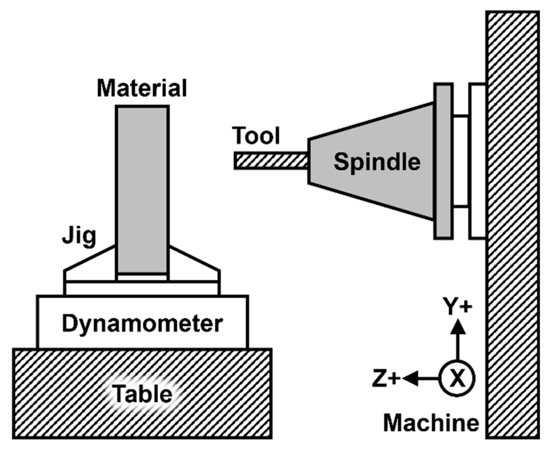
Figure 2.
Schematic of the cutting process and chip formation mechanism in the LF-VAD process.
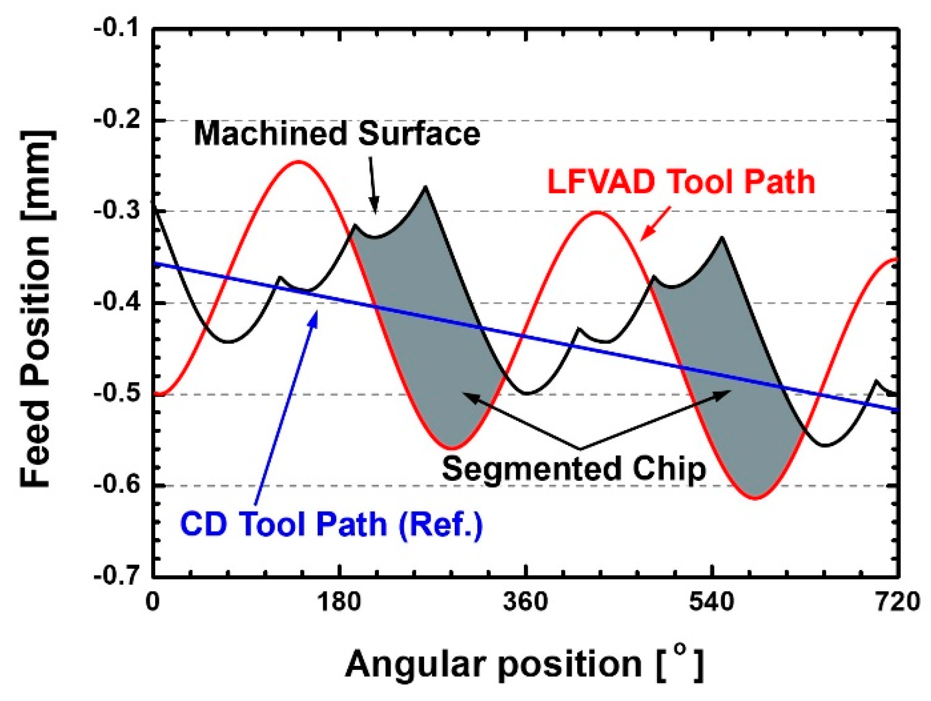
Figure 3.
Comparison of cutting forces due to the difference in cutting methods between LF-VAD and CD processes (Vc: 40 m/s, Coolant Pressure: 40 bar, 20 Pass).
Figure 3.
Comparison of cutting forces due to the difference in cutting methods between LF-VAD and CD processes (Vc: 40 m/s, Coolant Pressure: 40 bar, 20 Pass).
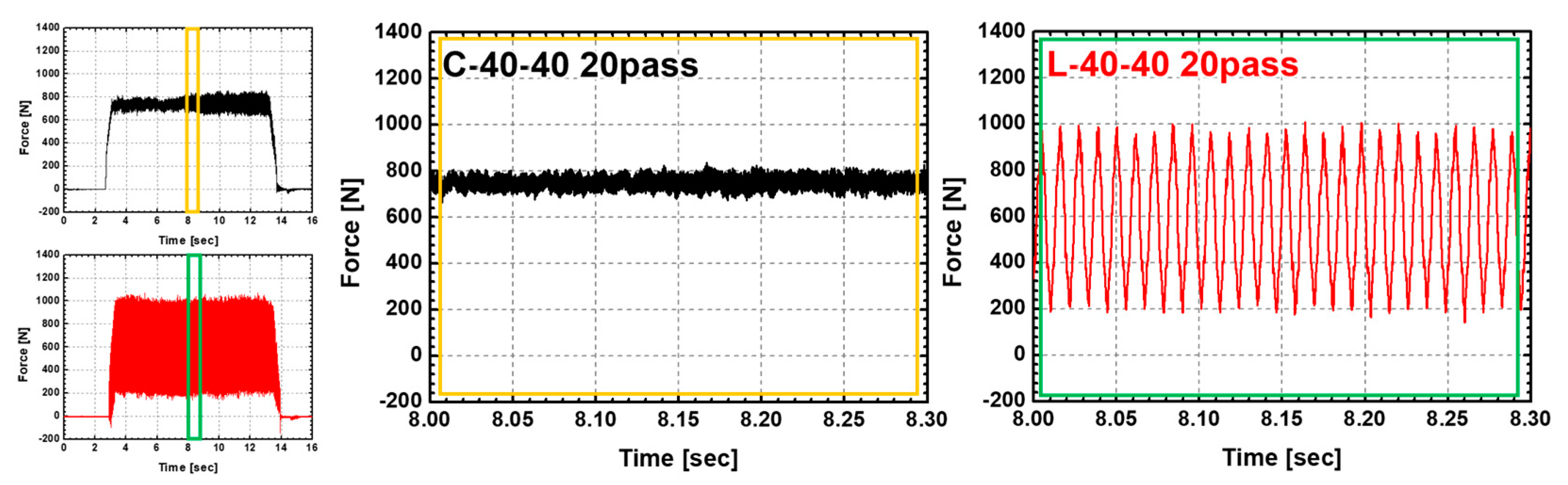
Figure 4.
Segmentation and evacuation of chips based on machining conditions.
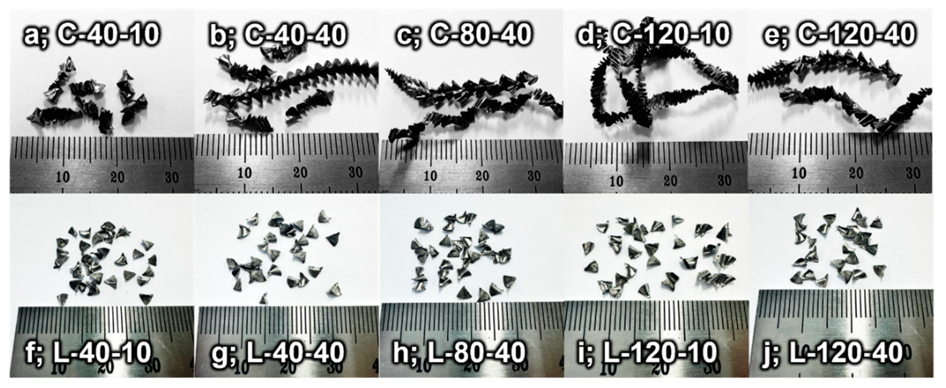
Figure 5.
Comparison of phase morphology of ti-6Al-4V ELI chips under different coolant pressures.
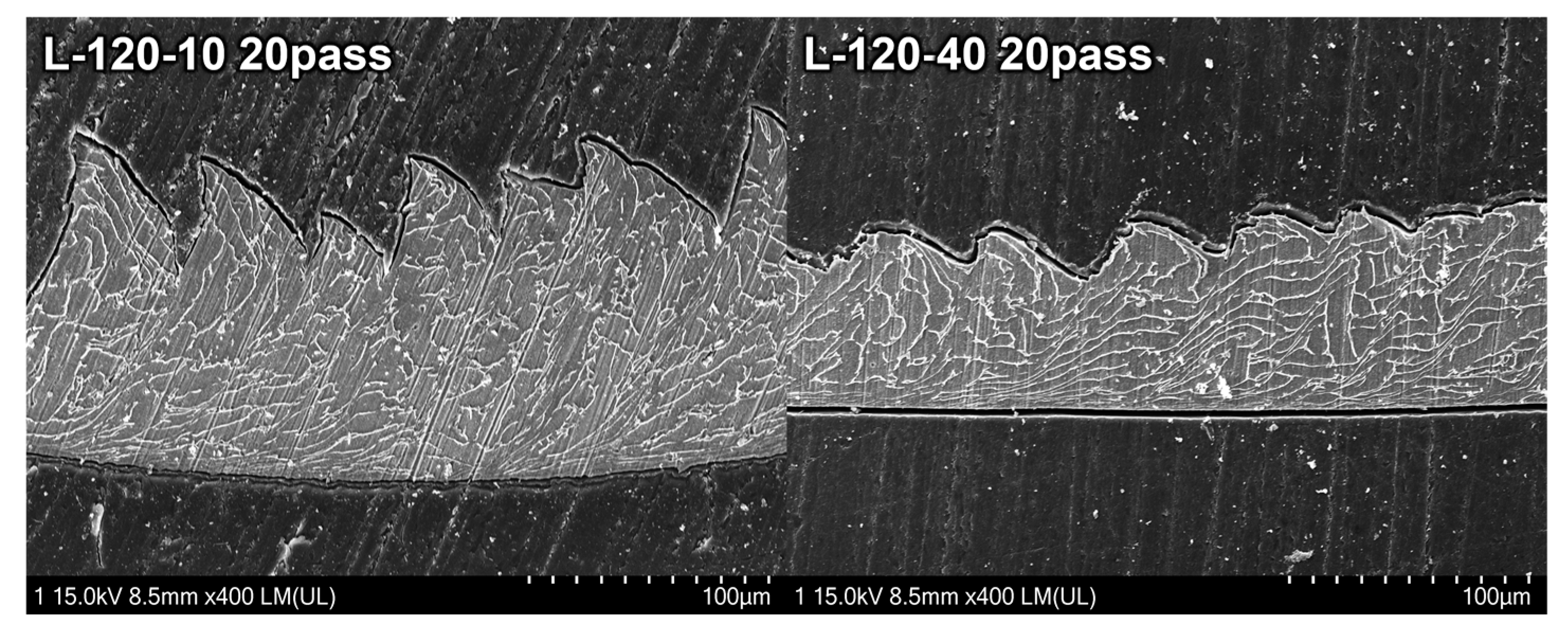
Figure 6.
Wear of chisel edge area under different processing conditions.
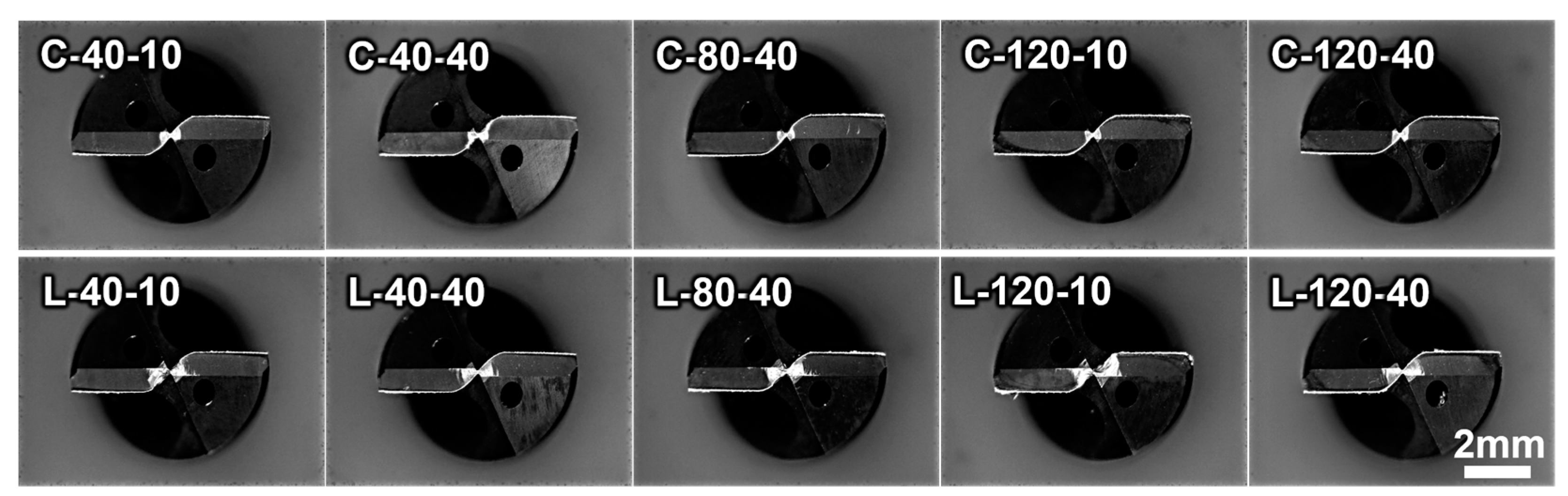
Figure 7.
Comparison of surface roughness (Ra) at 20 pass according to processing conditions and cutting speeds.
Figure 7.
Comparison of surface roughness (Ra) at 20 pass according to processing conditions and cutting speeds.
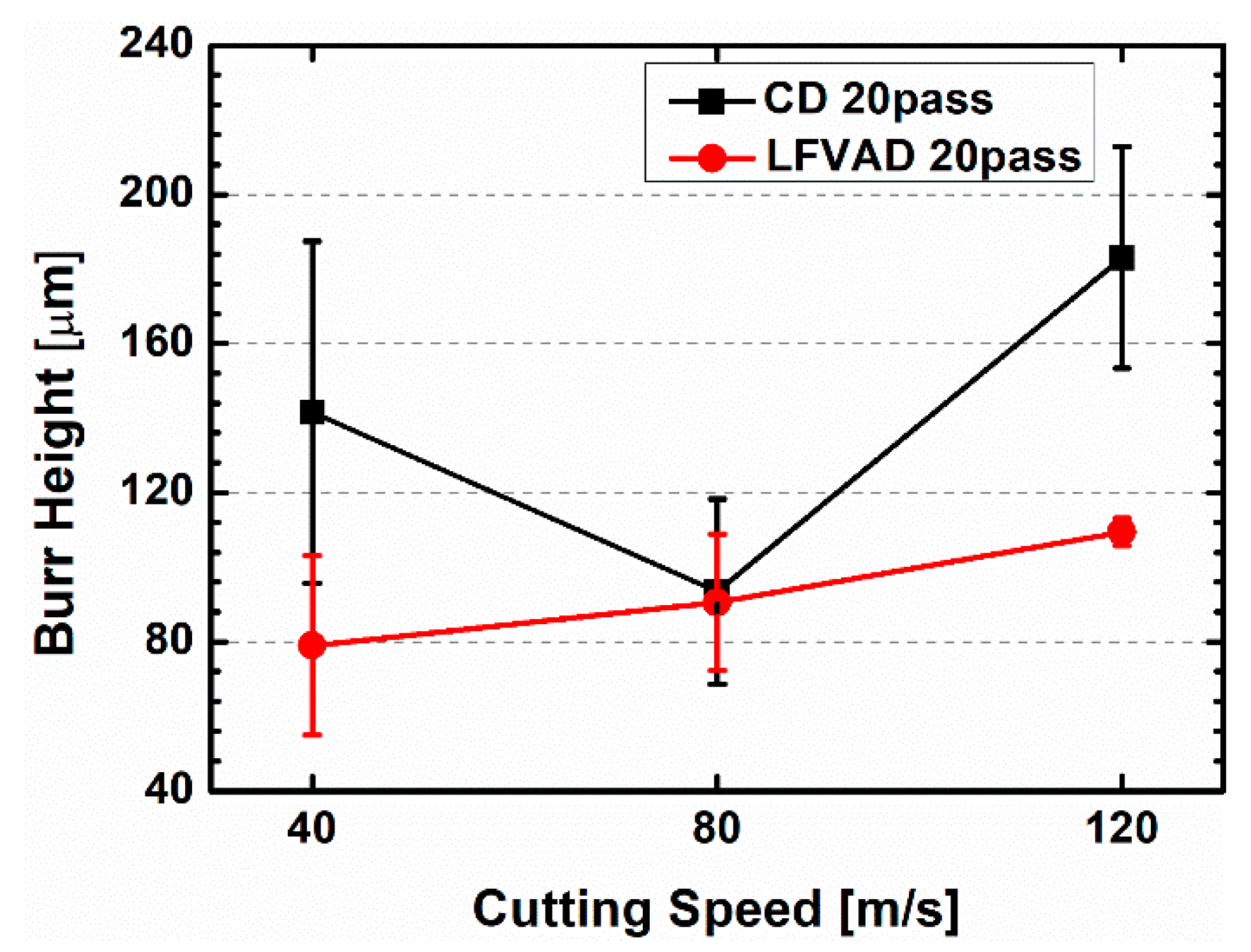
Figure 8.
Comparison of burr height at 20 pass according to processing conditions and cutting speeds.
Figure 8.
Comparison of burr height at 20 pass according to processing conditions and cutting speeds.
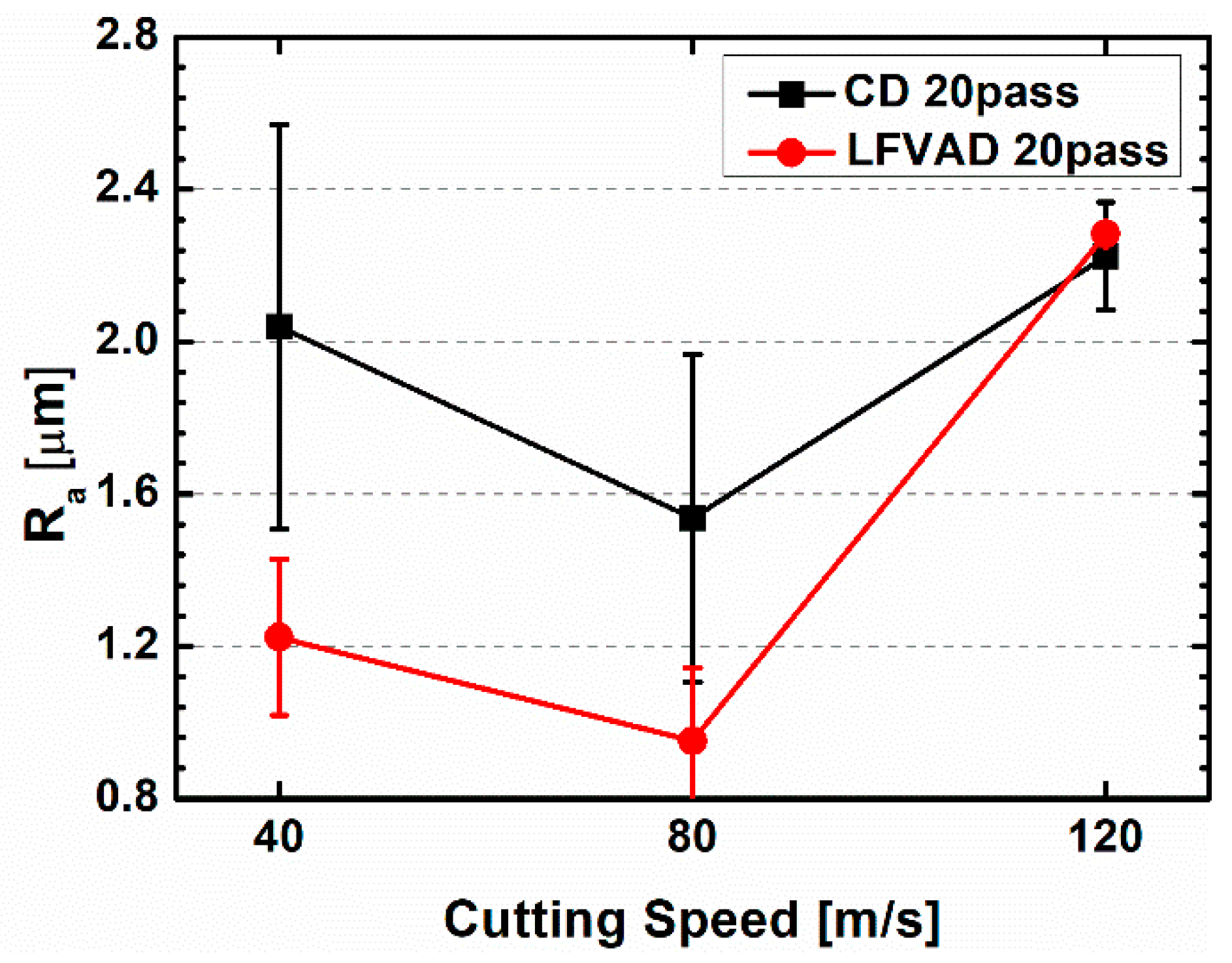
Figure 9.
Comparison of residual stresses depending on the cutting process and cutting speed.
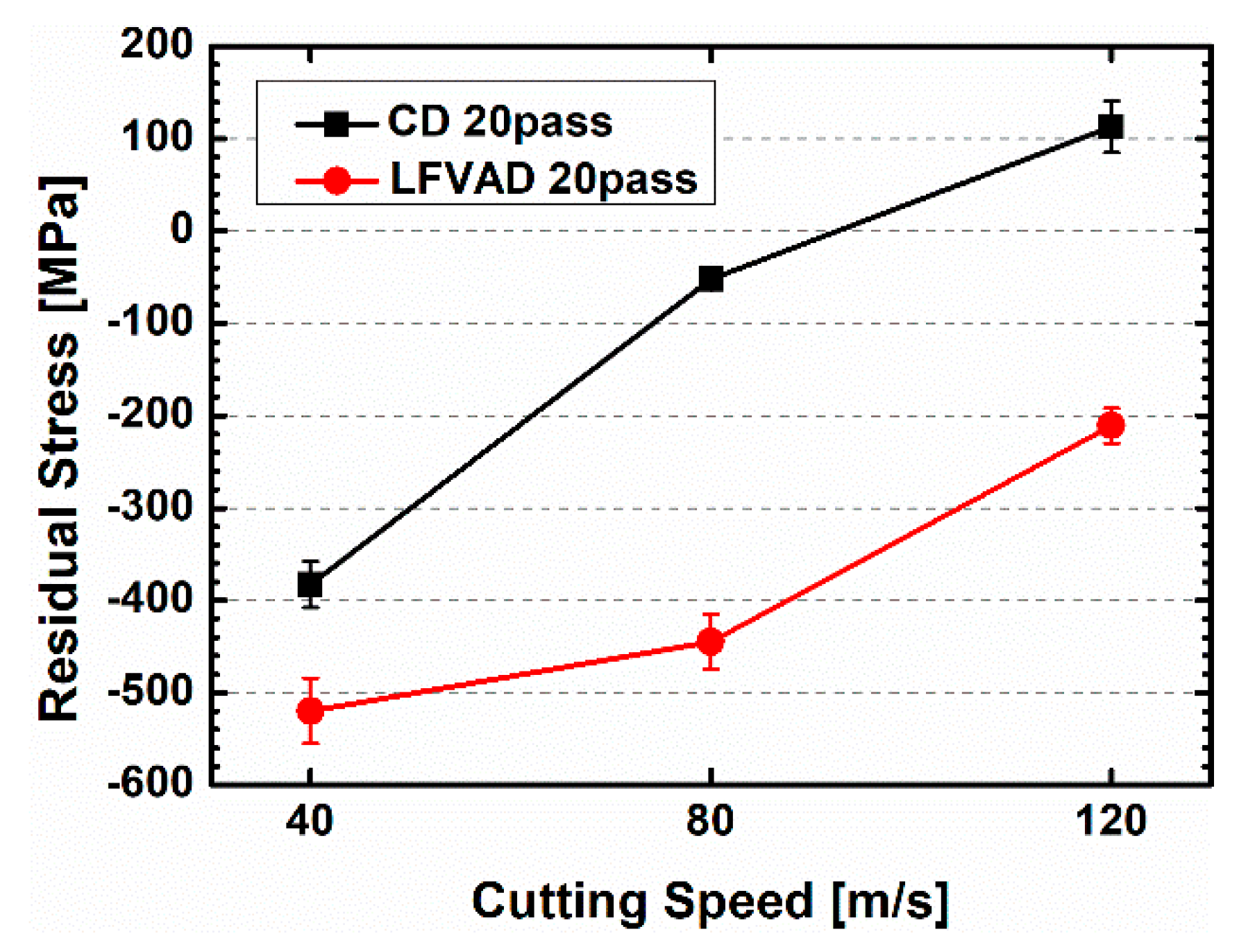

Table 1.
Specifications of the drill used in the experiments (DH452060, YG-1).
| Coating Material | TiAlN |
| Diameter [mm] | 6 |
| Point Angle [°] | 140 |
| Helix Angle [°] | 30 |
| Cutting Length [mm] | 44 |
| Total Length [mm] | 82 |
Table 2.
Mechanical properties of the materials used in the experiments[30].
Table 2.
Mechanical properties of the materials used in the experiments[30].
| Mechanical Property | Ti-6Al-4V | Ti-6Al-4V ELI |
| Vickers Hardness | 349 | 341 |
| Tensile Strength, Ultimate [MPa] | 950 | 860 |
| Tensile Strength, Yield [MPa] | 880 | 790 |
| Modulus of Elasticity [GPa] | 113.8 | 113.8 |
| Charpy Impact [J] | 17 | 24 |
| Fracture Toughness [MPa·m1/2] | 75 | 100 |
| Reduction of Area [%] | 36 | 15 |
Table 3.
Cutting force trends by processing conditions and passes.
Disclaimer/Publisher’s Note: The statements, opinions and data contained in all publications are solely those of the individual author(s) and contributor(s) and not of MDPI and/or the editor(s). MDPI and/or the editor(s) disclaim responsibility for any injury to people or property resulting from any ideas, methods, instructions or products referred to in the content. |
© 2023 by the authors. Licensee MDPI, Basel, Switzerland. This article is an open access article distributed under the terms and conditions of the Creative Commons Attribution (CC BY) license (http://creativecommons.org/licenses/by/4.0/).
Copyright: This open access article is published under a Creative Commons CC BY 4.0 license, which permit the free download, distribution, and reuse, provided that the author and preprint are cited in any reuse.


