
Submitted:
11 February 2025
Posted:
13 February 2025
You are already at the latest version
Abstract
The present paper deals with warping torsion, bending and axial forces. Presenting a method to compute the shear center of the effective section, the warping constant and warping coordinates needed to compute the stresses due to the bimoment. The stresses are compared between stresses in the gross and effective section when a Bimoment only is applied for the sake of simplicity but any combination with axial and biaxial bending moment is allowed. This paper fills the gap of the current codes to deal with bimoment in Class 4 sections.
Keywords:
warping torsion
; bimoment
; Class 4 section
; effective width
1. Introduction
Elastic Theory
The classical approach to determining section properties is presented including sectorial coordinates using centroidal coordinates yc and zc see Figure 1 (a) and (b).
( can be chosen arbitrarily, typically taken as 0)
( can be chosen arbitrarily, typically taken as 0)
It is convenient computationally to use any arbitrary starting coordinate system (y, z, ω) and the parallel axis theorem to obtain the centroidal properties. For sectorial coordinates with respect to any pole,
The normalized sectorial coordinates about the shear center can then be determined using
Once the stresses are computed the effective width of each is plate is computed, the effective width depend on the Axial force N, bending moments My, Mz and Bimoment B combination according to EN 1993-1-1:2022 [1] and EN 1993-1-5:2006 [2] Lee [3].
2 methods can be used to compute the stresses:
Method 1: Consider each internal force independently and compute its stresses with the effective section.
Method 2: Consider all the internal forces simultaneously and compute the stress distribution to altogether and the effective width related to those stresses.
Now taking into account the effective width the effective section properties are computed starting with:
- Centroid, second moment of area about the y and z axes and product of inertia (Iyeff, Izeff, Iyzeff))
- Shear center, warping coordinates and warping constant (Iweff).
The warping with respect to any pole can be obtained as usual, the mean value wmean,eff takes into account that only the effective areas are considered, as well to compute the shear center position of the effective section Iyw,eff and Izw,eff have to be computed for the effective section, finally the warping constant Iw,eff of the effective section is computed.
- Due to possible shift of the centroid there will be a change in the bending moments (Myeff,Mzeff).
Following the stresses in the effective section are computed:
The coordinates yeff and zeff are referred to the effective centroid, while the warping weff is referred to the new shear center.
2. Numerical Examples
The following software is used by Agüero [4] :
In this software 10 fibers are used per element, more accurate in case the number of fibers is increased.
Following examples to compute section properties in class 4 sections comparing the results for the gross and effective section when a Bimoment is applied. The material used is steel S355
2.1. I Shape Section 2 Axes of Symmetry
Section dimensions b=30cm h=30cm t=0.4cm
Gross section:
Iw=405000cm6
Centroid and shear center in the intersection 2 axes of symmetry
Effective section:
Iweff=169282cm6
Centroid and shear center (the effective section is point symmetric)
To obtain the effective width [2] is used:
k σ=0.57 therefore λp=2.1496 , ρ=0.424 and the effective width of the compression is flange=0.424*15=6.36cm
2.2. Monosymmetric Section
Channel section stresses Figure 4:
Section dimensions b=15cm h=30cm t=0.4cm
Section properties:
Gross section:
Iw=88593cm6
The origin of the reference system is at the intersection bottom flange and web.
Centroid position in the axis of symmetry: Zg=15 Yg=3.75
and shear center in the axis of symmetry: Zsc=15 Ysc=-5.625
Effective section:
To compute the effective part of the bottom flange. Taking into account that ψ=-0.6 , kσ=0.72, λp=1.91 , ρ=0.47 , the part of that flange under tension is 5.624cm and the effective part under compression is ρ*bc=4.4cm, the remaining part of the flange is 15-4.4-5.624=4.96cm length that has to be removed.
Iweff=53730cm6
Centroid position: Ygeff=3.06 Zgeff=16.12
and shear center: Zsceff=9.63 Ysceff=-7
2.3. Non Symmetric Section
Channel non symmetric section:
Section dimensions top flange width bu=15cm, bottom flange width bl=30cm tf=0.4cn h=30cm tw=0.2cm
Section properties and stresses Figure 5:
Gross section:
Iw=135000cm6
The origin of the reference system is at the intersection bottom flange and web.
Centroid position in the axis of symmetry: Zg=11.25 Yg=9.375 and shear center in the axis of symmetry: Zsc=5 Ysc=-7.5
Effective section:
Iweff=88379cm6
Centroid position: Zgeff=13.27 Ygeff=6.44 and shear center: Zsceff=-0.637 Ysceff=-7.83
3. Conclusions
The present paper deals with warping torsion, bending and axial forces. Presenting a method to compute the shear center of the effective section, the warping constant and warping coordinates needed to compute the stresses due to the bimoment. The stresses are compared when a Bimoment only is applied for the sake of simplicity but any combination with axial and biaxial bending moment is allowed. This paper fills the gap of the current codes to deal with bimoment in Class 4 sections.
Funding
This research project is supported by the Slovak Grant Agency VEGA no. 1/0155/23.
Nomenclature
according to the Eurocode3
References
- EN 1993-1-1:2022; Eurocode 3: Design of Steel Structures. Part 1-1: General Rules and Rules for Buildings. CEN: Brussels, Belgium, 2022.
- EN 1993-1-5:2006; Eurocode 3: Design of steel structures - Part 1-5: General rules - Plated structural Elements.
- Lee, C.K.; Chiew, S.P. A review of class 4 slender section properties calculation for thin-walled steel sections according to EC3. Advanced Steel Construction 2019, 15, 259–266. [Google Scholar]
- Agüero, A. , “Thin wall section Class 1,2,3 & 4” Software, Online available from https://labmatlab-was.upv.es/webapps/home/thinwallsectionmaterials_class4.html, 2024.
Figure 1.
General thin walled section.
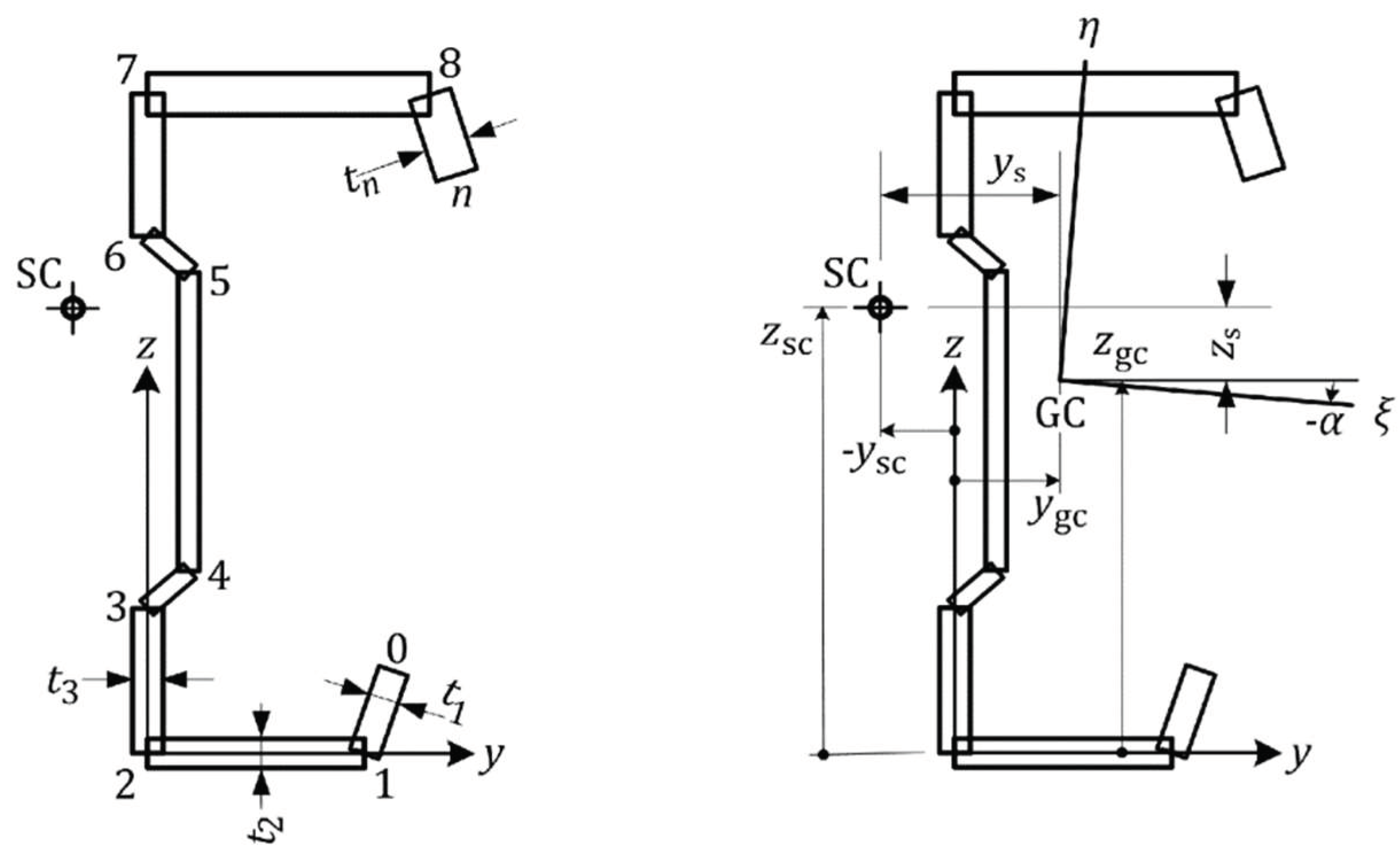
Figure 2.
Gross intital section and effective section in case bimoment on Class 4 section I shape.
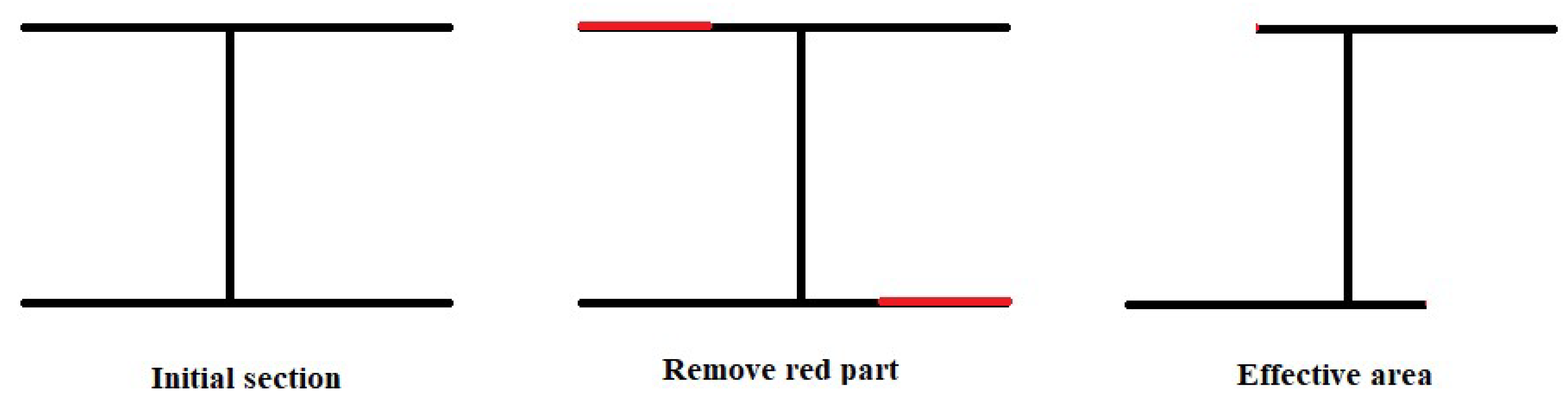
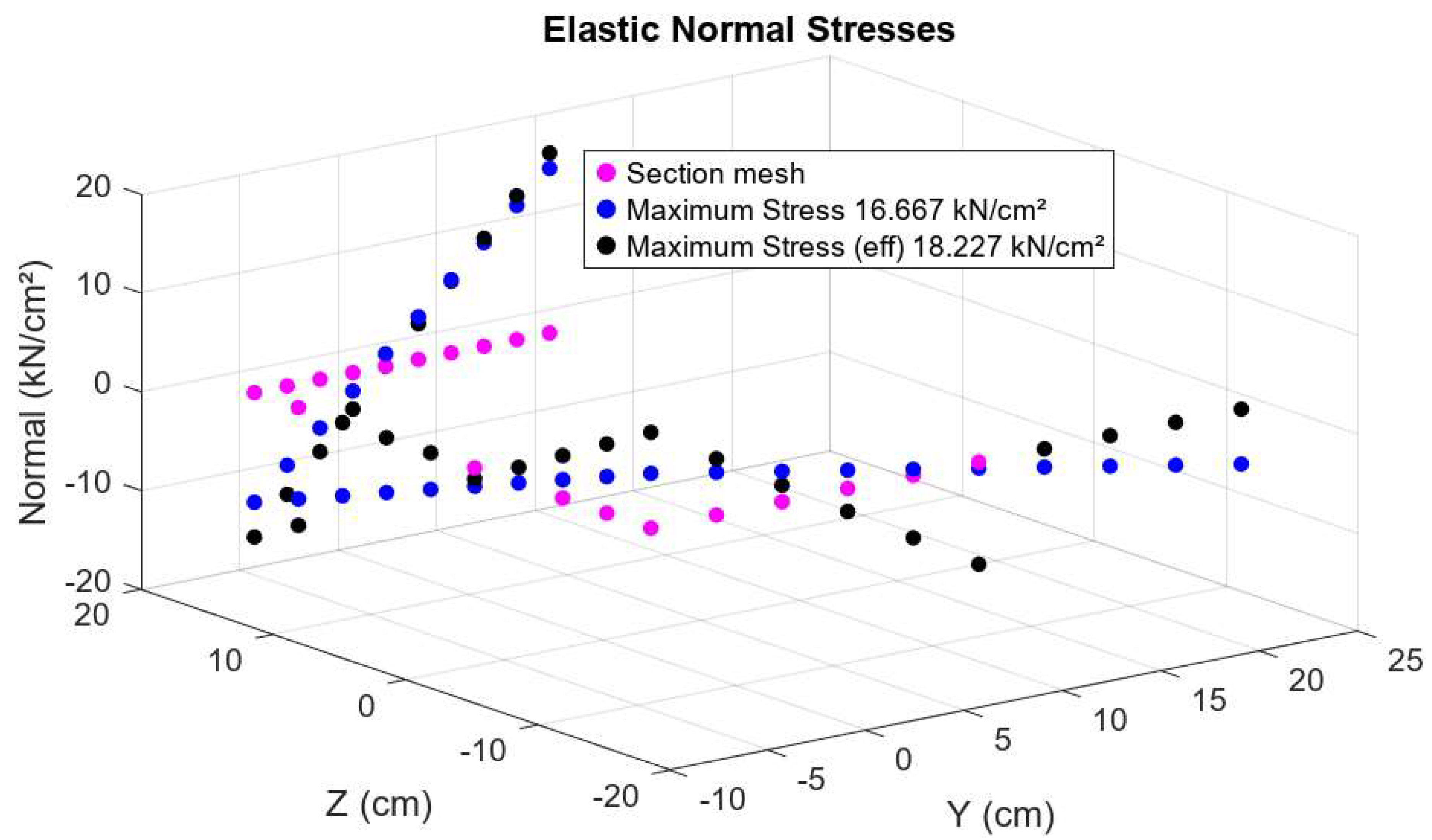
Figure 3.
stresses in the gross (Blue) and effective (Black) section due to a bimoment B=10000kNcm2.
Figure 3.
stresses in the gross (Blue) and effective (Black) section due to a bimoment B=10000kNcm2.
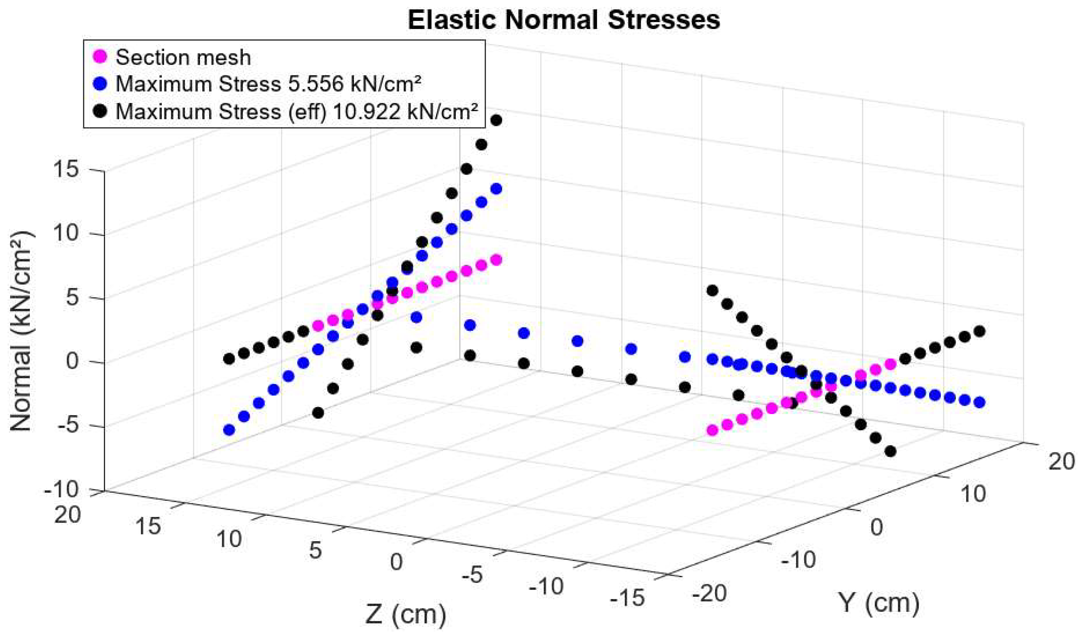
Figure 4.
stresses in the gross (Blue) and effective (Black) section due to a bimoment B=10000kNcm2.
Figure 4.
stresses in the gross (Blue) and effective (Black) section due to a bimoment B=10000kNcm2.
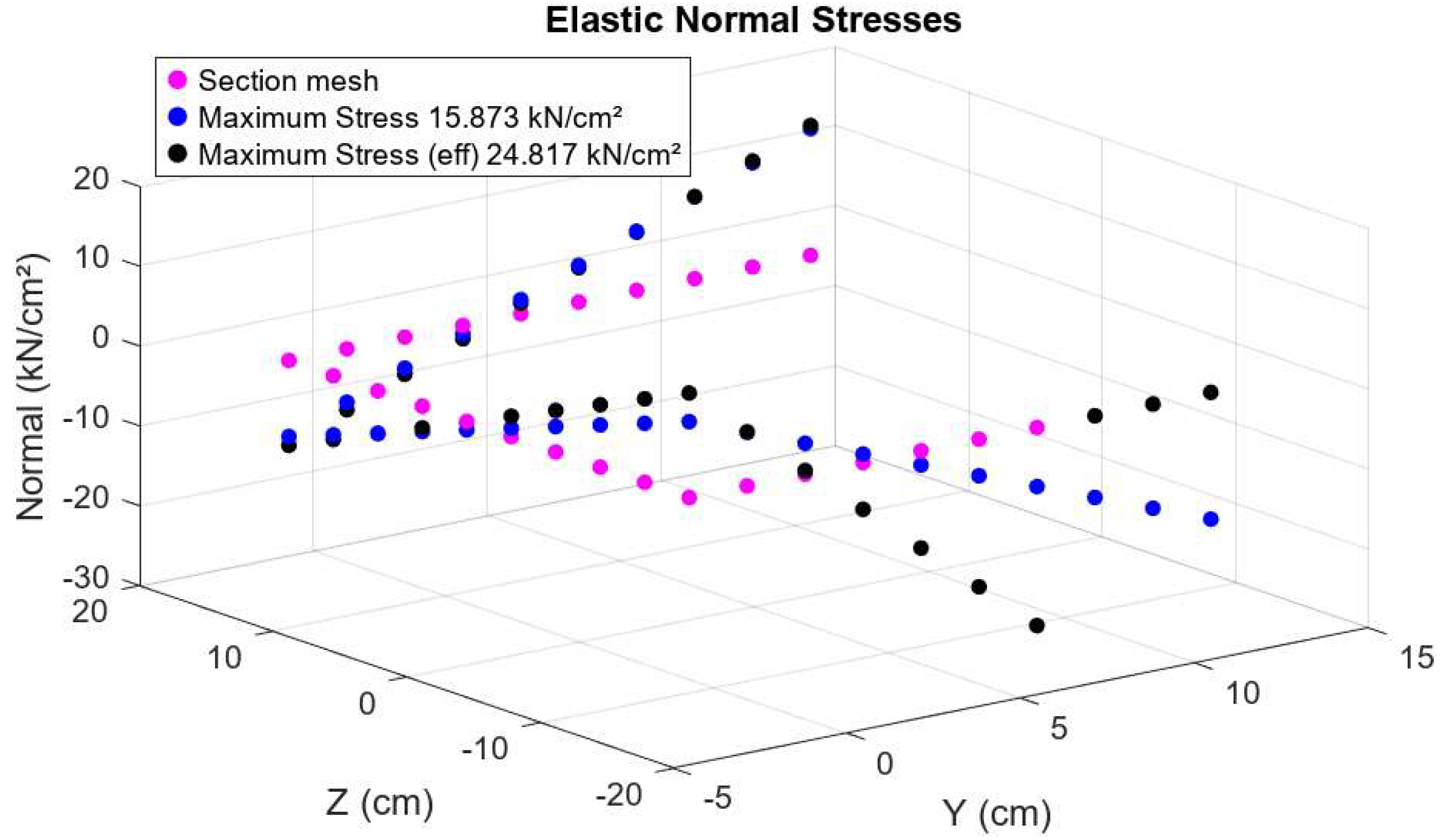
Figure 5.
stresses in the gross (Blue) and effective (Black) section due to a bimoment B=10000kNcm2.
Figure 5.
stresses in the gross (Blue) and effective (Black) section due to a bimoment B=10000kNcm2.
Disclaimer/Publisher’s Note: The statements, opinions and data contained in all publications are solely those of the individual author(s) and contributor(s) and not of MDPI and/or the editor(s). MDPI and/or the editor(s) disclaim responsibility for any injury to people or property resulting from any ideas, methods, instructions or products referred to in the content. |
© 2025 by the authors. Licensee MDPI, Basel, Switzerland. This article is an open access article distributed under the terms and conditions of the Creative Commons Attribution (CC BY) license (http://creativecommons.org/licenses/by/4.0/).
Copyright: This open access article is published under a Creative Commons CC BY 4.0 license, which permit the free download, distribution, and reuse, provided that the author and preprint are cited in any reuse.


