
Submitted:
11 February 2025
Posted:
12 February 2025
You are already at the latest version
Abstract
Traditional conservation strategies often prioritize minimizing water use; nevertheless, water can also enhance thermal comfort by incorporating a water to air heat exchanger (WAHE) alongside non-direct evaporative and radiant cooling techniques. A WAHE can be installed in features such as ponds, water tanks, or rainwater cisterns. This article assesses the cooling potential of two prototypes of roof ponds and a green roof connected to WAHE. Several testing units measuring 1.35 x 1.35 x 1.35 meters with identical heat characteristics, excluding the roof, were constructed and tested. In the first system, the heat that the green roof could not absorb was transferred to a water reservoir and then dissipated to the outside. The first roof pond prototype features a 0.35 cm deep water pond topped with a 0.03m thick insulating panel and a spray system. The second roof pond variant has an aluminum sheet with a 0.10m air gap above a 0.25m deep water pond. Several test series were conducted over a year, and a comparison was made with a baseline unit that meet California's energy code standards. The results suggest that combining a WAHE with different roof configurations offers promising benefits while keeping water consumption limited.
Keywords:
energy conservation
; physical testing – mockups
; roof pond
; green roof
; water-to-air heat exchanger
; passive cooling
1. Introduction
The construction industry contributes to about 35% of global carbon emissions [1]. Accordingly, significant efforts and resources have been used to achieve low energy consumption buildings [2]. Roofs have a critical role in this issue, as they can contribute substantially to heat gains during hot periods because of direct solar radiation. Studies indicate that in hot climates, roofs alone account for around 50% of the thermal loads in one-story buildings [3]. Nevertheless, roofs have significant potential to dissipate heat through mechanisms like conduction, longwave radiation and evaporative cooling [4].
Traditional methods for reducing solar heat gain through roofs typically involve increasing thermal insulation and heat storage capacity. However, green roofs offer an alternative solution as they reduce the incidence of solar radiation by shading the roof surface, which is especially useful in hot climates [5,6,7]. Research on green roofs has explored their energy-saving potential, along with various other benefits [8,9,10]. These research studies have demonstrated that green roofs can lower cooling energy demand by 2-48% [11,12,13]. Factors such as plant species, depth of the growing medium, and plant density have also been identified as key contributors to the cooling effectiveness of indoor thermal environments [14,15,16,17].
On the other hand, roof ponds also offer several advantages for cooling purposes because the water's high thermal inertia helps to reduce peak temperatures. The concept of roof pond was likely first explored by Jeffrey Cook [18]. In the 1970s, the "skytherm" system, which utilizes nocturnal radiation for cooling, was introduced [19]. Later, in 1994, Givoni [20] assessed the performance of roof ponds with fixed shading and insulation. Additionally, groundbreaking thermally active construction systems that leverage rainwater cisterns have been implemented [21]. Research on roof ponds has significantly increased in recent years. In 2008, a mechanically ventilated roof pond was evaluated, reporting promising outcomes in terms of passive cooling [22]. Moreover, other researchers have reviewed the advancements and variations in roof pond technologies [23,24].
Recent studies have explored hybrid passive cooling systems that combine conventional passive methods with other passive strategies, aiming to assess their cooling performance and suitability under various conditions. Among these, earth to air heat exchangers (EAHE) have been widely investigated as systems that utilize the ground’s thermal properties for heat storage and dissipation in conjunction with other passive techniques [25,26]. Due to the soil's high thermal mass, temperature fluctuations below the surface are much smaller compared to those at ground level. Numerous models have been developed to analyze the energy efficiency of EAHE systems [27]. Benkert et al. created a mathematical model validated through experiments [28]. Moreover, the EAHE system efficiency was also assessed taking into account the influence of key boundary conditions [29].
While EAHE systems are gaining popularity, there has been comparatively less research about WAHE systems. However, WAHEs have some advantages over EAHEs because water dissipates heat more effectively than earth due to its higher thermal capacity and conductivity [30,31]. The WAHE system was patented by Richard Bourne and David Springer in 1992 [32].
The review of existing studies indicates that some efforts have been devoted in recent years to investigating green roofs and roof ponds. However, a comparative study of the combined impact of these passive systems with a WAHE has not been thoroughly done. This study experimentally evaluates the passive cooling potential of a green roof and two roof pond variants conductively coupled with the indoor space. To achieve this, testing units with identical thermal envelopes, differing only in their roof designs, were constructed and evaluated in Southern California. The study also assessed the impact of a WAHE on the cooling efficiency of all roof configurations. The results were compared to a baseline unit featuring an insulated roof that meet the energy code standards of California.
2. Configuration of the Test Systems
To assess the advantages of using different roof prototypes along with a WAHE system, testing units were constructed at the Lyle Center for Regenerative Studies at Cal Poly Pomona University which is situated near Los Angeles (California), in a climate with hot dry summers and moderate winters. Analysis of the Climatic parameters and design recommendations from the nearby Chino airport weather station are presented in the following chart (Figure 1).
The dimension of all testing units was 1.35 x 1.35 x 1.35 meters and they were oriented south, with a slight 10-degree rotation toward the west. All testing units were constructed using identical dimensions and materials for the walls, windows, and floor. However, the roof differed based on the different configurations (Table 1). The thermal transmittance of the floor was 0.299 W/m²K, while the walls thermal transmittance was 0.308 W/m²K. To minimize heat gain, the walls were painted white. A 610 mm by 610 mm (2’ by 2’) double-glazed window was placed on the wall facing south. The window was evaluated with shading. For night ventilation, a 4-inch air extractor and an intake vent were placed on opposite walls. Furthermore, 89 mm wheels were installed beneath the test units to allow for adjustment of orientation and location. We have built and compared two roof pond variants and a green roof connected to a WAHE with a baseline unit that has an insulated roof that meets California's energy code standards (Figure 2).
Data loggers were positioned in several locations to record thermal parameters, such as dry bulb temperature and mean radiant temperature, as well as relative humidity in 5-minute intervals. We have used Onset devices with a measurement spectrum of 0 to +100 °C and precision of ±0.5 °C. Calibration was performed prior to measurements to ensure proper functionality of the system. Figure 3 and Figure 4 displays the sensor locations in the testing units.
The table below shows the layers and thermal characteristics of the testing unit along with all roof configurations, including the baseline unit (Table 1).
2.1. Configuration of the Green Roof
We have tested a green roof due to its growing popularity and superior cooling potential compared to traditional roofs [33]. Succulents having a LAI of 4 were planted on the green roof. The roof measured 1.35 x 1.35 meters and had a soil depth of 130 mm, placed over 20 mm of gravel, a waterproof membrane, and a metal plate reinforced by 2” x 4” joists. The roof was gently sloped to ensure proper drainage, and a drainage conduit was installed at the end of the metal plate to capture and recycle excess irrigation water (Figure 5).
2.2. Configuration of the Roof Pond with Insulation and Nighttime Spraying
A pond 0.35 meters in depth was located on the roof. It was sheltered by a 3 cm thick floating polystyrene insulation layer. Previous studies have shown that increasing thickness beyond this value does not significantly enhance performance [34]. A spray system is positioned above the pond to flow water across the insulation at night, cooling the water through radiation and evaporation [33]. The external face of the insulation is painted white to reflect direct solar radiation during the day while promoting long-wave radiation at night. The spraying system is located 0.5 meters over the insulation layer, which is the lowest height needed for effective evaporative cooling [35]. The roof’s supporting structure consists of a metal plate that provides efficient heat transfer to the interior space. This thermal-insulated roof pond system was designed by Givoni and experimentally assessed with La Roche [36].
During the day, the insulation layer helps reduce water overheating. At night, however, the water cools naturally via evaporation and long-wave radiation towards the sky. Previous studies have indicated that this system provides a stronger cooling effect than an uncovered pond with spraying, and performs nearly the same as a shaded and ventilated pond [37]. Moreover, when the external wet bulb temperature exceeds the water temperature the spray system can heat the water [38]. Therefore, the spray operates only at night (between 7:00 p.m. and 7:00 a.m.) to enhance the system efficiency and minimize water loss through evaporation (Figure 6).
2.3. Configuration of the Roof Pond Sealed by an Aluminum Sheet
This prototype is an evapo-reflective roof featuring a 25 cm deep water pond, covered by a flat aluminum sheet separated from the water by a 10 cm air gap. The roof pond is securely sealed to avoid water lost through evaporation. The exterior surface of the aluminum sheet is coated in white paint to improve its reflective capabilities (Figure 7). During the nighttime, the aluminum sheet’s temperature drops beneath water temperature, causing condensation of water vapor. Heat is thus dissipated to the outside. An adaptive numerical model for a similar aluminum-covered pond roof previously designed by Ben Cheikh and Bouchair [39]. This model was later discussed and compared with other pond roof variants [23]. The pond roof is upheld by a metal plate that ensures effective heat transfer to the indoor air of the testing unit.
2.4. Configuration of the WAHE
A pipe links the interior of the testing units to all roof ponds and a water pond that matches the floor dimensions of the testing units (1.35x1.35 meters) and is 0.35 m deep in the case of the green roof. The pond’s water is utilized to lower the temperature inside the testing units via a WAHE. A ventilator circulates air from the testing units to the ponds through a WAHE placed within the pond's water. The air conveys heat to the submerged pipeline through convection, which subsequently transfers the heat to the water by conduction but in the liquid. Finally, the pre-cooled air is reintroduced into the testing unit to decrease the indoor temperature.
A PVC conduit encased in batt insulation, waterproof liner and aluminum foil, channels air from the interior of the testing units to the pond. Conversely, a flexible uninsulated aluminum pipe placed underwater enhances the pipe’s thermal conductivity to enhance the WAHE system efficiency. The underwater aluminum pipe has a diameter of 10.16 cm (4 inches) and a length of 3.5 meters (Figure 5, Figure 6 and Figure 7). The fan operates continuously, both day and night, with a flow speed of 1.5 m/s to consistently lower the interior temperature.
3. Analysis of Findings
The authors have selected various test series conducted between June and August 2022 in order to compare the performance of all roof variants with a baseline unit that meets California's energy regulations. To assess the WAHE impact on all roof configurations, we have conducted multiple series with the WAHE system both active and inactive. The parameters used to assess the system's efficiency include the cooling performance of the pond water and the influence of all roof designs on cooling the space beneath through conductive energy transfer. Additionally, the heat transfer efficiency of the WAHE and its effect on improving the cooling performance of all roof variants have been evaluated.
3.1. Green Roof
3.1.1. The WAHE Is Inactive
This series, which began on June 12th, assesses the cooling impact of the green roof. Maximum temperatures serve as a reliable measure of the system's cooling efficiency. Better performance is achieved when the difference between the maximum indoor and outdoor temperatures is higher, with the indoor temperature being lower. Findings indicate that when outdoor temperatures peak at approximately 35°C, the testing unit's interior temperature is about 3°C cooler, whereas the baseline unit’s maximum temperature is approximately 5°C lower than the outside temperature (Figure 8).
3.1.2. The WAHE Is Active
This series, starting on June 19th, analyzes the green roof’s cooling performance when the WAHE system is operating. The findings indicate that the WAHE significantly enhances the green roof's cooling potential. When outdoor dry temperatures exceed 35°C, the inside temperature is lowered by 9–10°C, which is 6°C more than when the WAHE system is not in operation.
The pond water temperature cools rapidly at night to align closely with the ambient temperature, typically dropping under 20°C. In the daytime, the water temperature warms by only about 2°C compared to its nighttime temperature, while the ambient temperature rises by approximately 15°C. Therefore, the pond’s water has a significant cooling potential, remaining over 10°C cooler than the outside temperature.
At night, the testing unit temperature closely matches the water temperature, helping to reduce the maximum temperature in the daytime. The thermal difference between the water and the air precooled by the WAHE system was under 2°C, confirming the efficient performance of the WAHE (Figure 9).
3.2. Roof Pond with Insulation and Nighttime Spraying
3.2.1. The WAHE Is Inactive
This series, initiated on July 3rd, evaluates the cooling efficiency of a roof pond protected by floating insulation and nighttime spraying. The WAHE does not operate in this series. The findings demonstrate the effective cooling potential of this roof pond configuration (Figure 10). When the outdoor temperature exceeds 35°C, the inside temperature of the testing unit remains below 27°C, around 8°C less. In contrast, the maximum temperature in the baseline unit is approximately 29°C, 2°C above the testing unit. Therefore, the testing unit provides superior cooling performance compared to the baseline unit that complies with California's energy regulations.
3.2.2. The WAHE Is Active
This series, starting on July 17th, assesses the same roof setup as in the previous series, but with the WAHE operating continuously, day and night. The findings show a significant improvement in system performance. When the ambient temperature is approximately 35°C, the maximum interior temperature remains under 25°C, approximately 3°C lower than when the WAHE is inactive. The maximum thermal difference between the pond water and the precooled air at the WAHE outlet is just about 1°C, indicating highly efficient heat transfer between the air flowing through the WAHE and the water.
The evaporation rate is 3.5 millimeters per day (approximately 6.3 liters). Additionally, the data reveal that air temperatures at the testing unit outlet and pond inlet, as well as at the pond outlet and testing unit inlet, are nearly identical. Thus, there is a negligible heat loss during air circulation through the pipes connecting the testing unit interior and the pond water (Figure 11). The evaporation rate is 3.5 millimeters per day, roughly corresponding to a daily water consumption of just 6.3 liters. Additionally, the data reveal that air temperatures at both the testing unit outlet and water pond inlet, as well as at the water pond outlet and testing unit inlet, are almost identical. Thus, there is negligible heat loss in the pipes linking the interior of the test units and the ponds (Figure 11).
3.3. Roof Pond Sealed by an Aluminum Sheet
3.3.1. The WAHE Is Inactive
This series, conducted on August 2nd, assesses the cooling potential of the roof pond sealed by an aluminum sheet when the WAHE is not working. The results indicate that the maximum temperature reached by the water is only a somewhat higher than in the case of a roof pond protected by floating insulation and nighttime spraying when the WAVE is not in operation. Nevertheless, the thermal difference between indoor and outdoor remains significant, around 7°C when the outdoor temperature is above 35°C. The baseline unit performance is slightly lower than the testing unit, reaching a maximum indoor temperature 1°C higher than the testing unit (Figure 12).
3.3.2. The WAHE Is Active
This series, starting on August 8th, evaluates the same previous configuration but with the WAHE in operation. The maximum indoor temperature of the testing unit is over 2°C lower than the maximum indoor temperature of the baseline unit, and the maximum temperature difference between inside and outside exceeds 8°C when ambient temperatures are above 35°C. These findings confirm that the WAHE system significantly enhances the roof pond’s cooling performance (Figure 13).
4. Comparison of Test Outcomes
We have used the temperature difference ratio (TDR) concept develop by Baruch Givoni [39] to compare series registered at different times and weather conditions. TDR is obtained by dividing the maximum outdoor temperature reduction in the indoor space by the daily thermal swing, as shown below.
TDR = (Tmaxi_out – Tmaxi_ins) / (Tmaxi_out – Tmini_out)
Where: Tmaxi_out = higher outside temperature (°C); Tmaxi_ins = higher inside temperature (°C); Tmini_out = lower outside temperature (°C).
The numerator signifies the thermal difference between the indoor and outdoor, whereas the denominator represents the difference between the maximum and minimum outside temperature. A greater TDR suggests more efficient cooling, since the difference between the inside and outside temperatures is higher.
TDR shows the potential to reduce the maximum indoor temperature based on the outdoor temperature swing, allowing for comparisons between different series taken in different periods. We have used the TDR concept to compare measured data in different roof configurations, both with the WAHE system on and off, as well as the baseline unit (Figure 14, Figure 15, Figure 16 and Figure 17). As TDR is computed on a daily basis, each of the points in Figure 14, Figure 15, Figure 16 and Figure 17 represents data from a single day and a trend line for each series is displayed to clarify the results. Figure 14 compares all roof configurations with the WAHE in operation and the baseline unit, while additional comparisons of performance are made with the WAHE on and off for the green roof (Figure 15), insulated roof (Figure 16), and roof pond with an aluminum sheet (Figure 17).
Figure 10 illustrates that all roof configurations with WAHE outperform the energy code compliant baseline unit. The insulated roof has the best performance, showing an improvement of 44% over the baseline unit. The following best performing roof configurations are the green roof and the aluminum roof, which are 38% and 31% better, respectively, when the daily outdoor temperature swing is 20°C.
Additionally, the findings indicate that when the WAHE is in operation, all roof configurations significantly increase their performance. Notably, during the time in which the WAHE is inactive the green roof decreases its efficiency by 47% shifting from 18% worse than the baseline unit to 22% better (Figure 15). Similarly, the insulated roof’s performance decreases by 22% (Figure 16) and the roof pond with an aluminum sheet drops by 13% (Figure 17). In both roof pond variants, the performance exceeds the baseline unit, even if the WAHE is inactive, around 29% and 21% respectively when the daily thermal amplitude is 20°C.
5. Temperature Difference Ratio (TDR) Estimation
Equations have been formulated based on the monitoring data to estimate the TDR for each roof configuration, as shown below.
Green roof (GR):
TDR = 0.019 * (Tmaxi_out– Tmini_out) – 0.094; R2 = 0.68.
Green roof + WAHE (GR + WAHE):
TDR = 0.013 * (Tmaxi_out – Tmini_out) + 0.340; R2 = 0.55.
Roof pond with floating insulation (INS):
TDR = 0.017 * (Tmaxi_out – Tmini_out) + 0.188; R2 = 0.91.
Roof pond covered with floating insulation + WAHE (INS + WAHE):
TDR = 0.010 * (Tmaxi_out – Tmini_out) + 0.481; R2 = 0.81.
Roof pond sealed by an aluminum sheet (AL):
TDR = 0.019 * (Tmaxi_out – Tmini_out) + 0.097; R2 = 0.94.
Roof pond sealed by an aluminum sheet + WAHE (AL + WAHE):
TDR = 0.016 * (Tmaxi_out – Tmini_out) + 0.235; R2 = 0.52.
The TDR of a building is determined by applying equations (2) – (7). The maximum indoor temperature in each case can be estimated by utilizing equation (1).
Tmaxi_ins = Tmaxi_out - [TDR * (Tmaxi_out – Tmini_out)].
Where the daily thermal amplitude needs to be acknowledged. The equations stated above, based on the results of on-site measurements, enable the maximum indoor temperature to be determined as a function of the maximum outdoor temperature and the daily thermal amplitude. They can be applied in real scenarios for south-facing buildings with shaded windows, low-mass walls and selected roof configuration to estimate the maximum inside temperature.
6. Conclusion
This study has experimentally assessed a green roof and two roof pond variants, along with the improvement of their cooling potential by incorporating an innovative water to air heat exchanger that moves air between the interior space of the testing units and a water pond.
The findings indicate the floating insulation roof with nighttime spraying combined with a WAHE is the most efficient. This configuration maintains indoor temperatures below 25°C when ambient temperatures exceed 35°C, representing a reduction of around 10°C. The insulated roof outperforms the baseline unit by 44%, followed by the green roof and the roof pond sealed by an aluminum sheet, which show improvements of 38% and 31%, respectively, when the daily thermal amplitude is over 20°C. In the case of the green roof, although the water pond is not connected to the interior space, it can offer substantial cooling. Additionally, the results indicate that all roof configurations significantly improve efficiency when the WAHE is in operation. Notably, when the WAHE is not operating the green roof decreases its performance by 47% shifting from 18% worse than the baseline unit to 22% better (Figure 15). Similarly, when the WAHE system is not in operation the insulated roof’s performance decreases by 22% (Figure 16) and the roof pond with an aluminum sheet drops by 13% (Figure 17). In both roof pond variants, the performance is better than the baseline unit, even if the WAHE is off, around 29% and 21% respectively, whilst the daily temperature swing is over 20°C.
The findings demonstrate that the WAHE is an efficient passive substitute to traditional active cooling systems. It provides substantial cooling in buildings by utilizing water reservoirs as thermal sinks. The water reservoir employed in this research is comparatively small in relation to the dimension of the testing units. This suggests that the evaluated systems would perform especially well with a larger water body.
Future studies should incorporate additional experiments to assess the efficiency of all roof configurations including the use of a fan sensor that recirculates indoor air through the WAHE or provides natural ventilation based on seasonal needs. Testing the system under more extreme conditions would help determine its operational limits. Additionally, developing numerical models and predictive equations is essential for adapting the system to different building types and climatic conditions.
Funding
This project was supported by a grant of the University of Seville for exchange mobility at the University of California.
Acknowledgments
The authors express their gratitude to Alan Locke for his generous assistance during their research at UCLA.
Conflicts of Interest
The authors declare no conflicts of interest.
References
- La Roche, P.; Berardi, U. Comfort and energy savings with active green roofs. Energy Build. 2014, 82, 492–504. [Google Scholar] [CrossRef]
- Ruiz-Valero, L.; Flores-Sasso, V.; Prieto-Vicioso, E.; Fernández-Flores, G. Assessment of Vernacular Housing in the Dominican Republic Using Simulations. Buildings 2024, 14(11), 3365. [Google Scholar] [CrossRef]
- Nahar, N.M.; Sharma, P.; Purohit, M.M. Studies on solar passive cooling techniques for arid areas. Energy Convers. Manag. 1999, 40, 89–95. [Google Scholar] [CrossRef]
- Wang, Y.; Wang, Z.; Rahmatollahi, N.; Hou, H. The impact of roof systems on cooling and building energy efficiency. Appl. Energy 2024, 376, 124339. [Google Scholar] [CrossRef]
- Joshi, M.Y.; Rodler, A.; Musy, M.; Guernouti, S.; Teller, J. Influence of urban morphology on potential of green roofs in regulating local microclimate: A case study of Liège, Belgium. Urban Climate 2024, 58, 102144. [Google Scholar] [CrossRef]
- Ouldboukhitine, S.E.; Belarbi, R.; Jaffal, I.; Trabelsi, A. Assessment of green roof thermal behavior: a coupled heat and mass transfer model. Build. Environ. 2011, 46, 2624–2631. [Google Scholar] [CrossRef]
- Joshi, M.Y.; Teller, J. Assessing urban heat island mitigation potential of realistic roof greening across local climate zones: A highly-resolved weather research and forecasting model study. Science of The Total Environment 2024, 944, 173728. [Google Scholar] [CrossRef]
- Parizotto, S.; Lamberts, R. Investigations of green roof thermal performance in temperature climate: a case study of an experimental building in Florianopolis city, Southern Brazil. Energy Build. 2011, 43, 1712–1722. [Google Scholar] [CrossRef]
- Berardi, U.; Ghaffarian, A. A critical analysis of the environmental benefits of green roofs. Appl. Energy 2014, 115, 411–428. [Google Scholar] [CrossRef]
- Berardi, U. The outdoor microclimate benefits and energy saving resulting from green roofs retrofits. Energy Build. 2016, 121, 217–229. [Google Scholar] [CrossRef]
- Dhahri, M.; Yüksel, A.; Aouinet, H. ; Di Wang; Arıcı, M.; Sammouda, H. Efficiency Assessment on Roof Geometry and Trombe Wall Shape for Improving Buildings’ Heating Performance. Buildings 2024, 14(5), 1297. [Google Scholar] [CrossRef]
- Wollschläger, N.; Schlink, U.; Trabitzsch, R.; Moeller, L. Weather dynamics affect the long-term thermal and hydrological performance of different green roof designs. Science of The Total Environment 2024, 957, 177376. [Google Scholar] [CrossRef]
- Qin, X.; Wu, X.; Chiew, Y.M.; Li, Y. A green roof test bed for storm water management and reduction of urban heat island effect in Singapore, Br. J. Environ. Clim. Change 2012, 2(4), 410–420. [Google Scholar] [CrossRef]
- Olivieri, F.; Di Perna, C.; D’Orazio, M.; Olivieri, L.; Neila, J. Experimental measurements and numerical model for the summer performance assessment of extensive green roofs in a Mediterranean coastal climate. Energy Build. 2013, 63, 1–14. [Google Scholar] [CrossRef]
- Jim, C.Y.; Tsang, S.W. Modeling the heat diffusion process in the abiotic layers of green roofs. Energy Build. 2011, 43(6), 1341–1350. [Google Scholar] [CrossRef]
- Liu, K.K.Y.; Minor, J. Performance Evaluation of an Extensive Green Roof, Green. In Proceedings of the Rooftops Sustainable Communities Conference, Washington D.C., 5-6 May 2015; pp. 1–11. [Google Scholar]
- Saqib, A.; Khan, M.S.U.; Rana, I.A. Bridging nature and urbanity through green roof resilience framework (GRF): A thematic review. Nature-Based Solutions 2024, 6, 100182. [Google Scholar] [CrossRef]
- Cook, J. Passive Cooling; MIT Press: London, UK, 1985. [Google Scholar]
- Hay, H.R.; Yellot, J. Natural air conditioning with roof pools and movable insulation. ASHRAE Transact. 1978, 75, 165–172. [Google Scholar]
- Givoni, B. Passive and Low Energy Cooling; Van Nostrand Reinhold: London, UK, 1994. [Google Scholar]
- Kalz, D.E.; Wienold, J.; Fischer, M.; Cali, D. Novel heating and cooling concept employing rainwater cisterns and thermos-active building systems for a residential building. Appl. Energy 2010, 87, 650–660. [Google Scholar] [CrossRef]
- Kharrufa, S.N.; Adil, Y. Roof pond cooling of buildings in hot arid climates. Build. Environ. 2008, 43, 82–89. [Google Scholar] [CrossRef]
- Sharifi, A.; Yamagata, Y. Roof ponds as passive heating and cooling systems: a systematic review. Appl. Energy 2015, 160, 336–357. [Google Scholar] [CrossRef]
- Spanaki, A.; Tsoutsos, T.; Kolokotsa, D. On the selection and design of the proper roof pond variant for passive cooling purposes. Renew. Sustain. Energy Rev. 2011, 15, 3523–3533. [Google Scholar] [CrossRef]
- Ascione, F.; Bellia, L.; Minichiello, F. Earth-to-air heat exchangers for Italian climates. Renew. Energy 2011, 36, 2177–2188. [Google Scholar] [CrossRef]
- Peretti, C.; Zarrella, A.; De Carli, M.; Zecchin, R. The design and environmental evaluation of earth-to-air heat exchangers (EAHE): a literature review. Renew. Sustain. Energy Rev. 2013, 28, 107–116. [Google Scholar] [CrossRef]
- Sodha, M.S. Simulation of periodic heat transfer between ground and underground structures. In Proceedings of the World Renewable Energy Congress VI, Pergamon, Brighton, 1–7 July 2000; pp. 965–968. [Google Scholar] [CrossRef]
- Benkert, S.; Heidt, F.D.; Scholer, D. Calculation tool for earth heat exchangers GAEA. In Proceedings of the Fifth International IBPSA (International Building Performance Simulation Association) Conference, vol. 2, Prague, Czech Republic, 8-10 September 1997. [Google Scholar]
- Zhao, J.; Huang, B.; Li, Y.; Zhao, Y. Comprehensive review on climatic feasibility and economic benefits of Earth-to-Air Heat Exchanger (EAHE) systems. Sustainable Energy Technologies and Assessments 2024, 68, 103862. [Google Scholar] [CrossRef]
- Soares, N.; Rosa, N.; Monteiro, H.; Costa, J.J. Advances in standalone and hybrid earth-air heat exchanger (EAHE) systems for buildings: A review. Energy Build. 2021, 253, 111532. [Google Scholar] [CrossRef]
- Wong, N.H.; Cheong, D.K.W.; Yan, H.; Soh, J.; Ong, C.L.; Sia, A. The effects of rooftop garden on energy consumption of a commercial building in Singapore. Energy Build. 2003, 35, 353–364. [Google Scholar] [CrossRef]
- Bourne, R.C.; Springer, D.A. Energy-saving Protected Roof Systems; Google Patents 1992. [Google Scholar]
- La Roche, P. Carbon-neutral architectural design, CRC Press: Boca Raton, FL, USA, 2012.
- Tavana, M.; Kammerud, R.; Akbari, H.; Borgers, T. A simulation model for the performance analysis of roof pond systems for heating and cooling; Lawrence Berkeley National Laboratory: Berkeley, California, USA, 1980; Available online: https://escholarship.org/uc/item/698610bd.
- Yannas, S.; Erell, E.; Molina, J.L. Roof cooling techniques: a design handbook; Earthscan: London, UK, 2000. [Google Scholar]
- La Roche, P.; Givoni, B. (2000) Indirect Evaporative Cooling with an Outdoor Pond. In Proceedings of the Passive and Low Energy in Architecture Conference, Cambridge, UK, 11-13 July 2000; pp. 310–311. [Google Scholar]
- Givoni, B. Indoor temperature reduction by passive cooling systems. Sol. Energy 2011, 85, 1692–1726. [Google Scholar] [CrossRef]
- Krüger, E.; Gonzalez, E.; Givoni, B. Effectiveness of indirect evaporative cooling and thermal mass in a hot arid climate. Build. Environ. 2010, 46(6), 1422–1433. [Google Scholar] [CrossRef]
- Ben Cheikh, H.; Bouchair, A. Passive cooling by evapo-reflective roof for hot dry climates. Renewable Energy 2004, 29, 1877–1881. [Google Scholar] [CrossRef]
Figure 1.
Chino airport’s psychrometric chart generated by Climate Consultant.
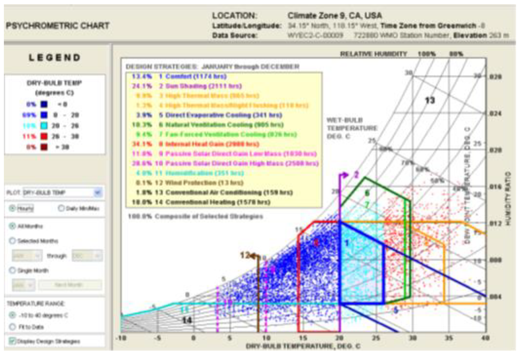
Figure 2.
Baseline unit that meets the energy code of California.
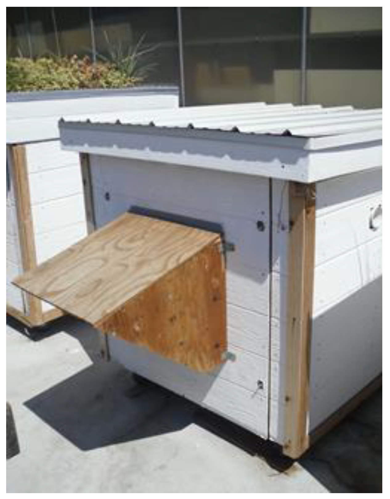
Figure 3.
Location of data loggers in the testing unit with a green roof connected to a water to air heat exchanger.
Figure 3.
Location of data loggers in the testing unit with a green roof connected to a water to air heat exchanger.
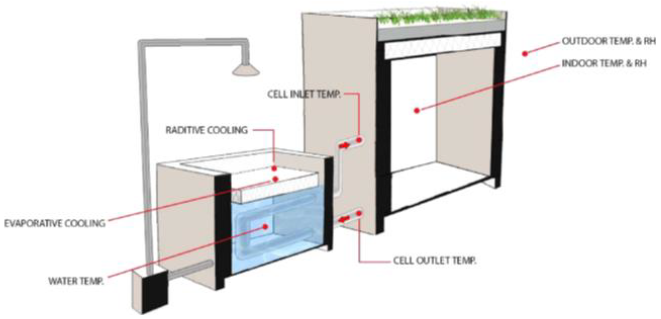
Figure 4.
Location of data Loggers in the testing unit with an insulated roof pond and nighttime spraying (left), and a roof pond sealed by an aluminum sheet with a WAHE (right).
Figure 4.
Location of data Loggers in the testing unit with an insulated roof pond and nighttime spraying (left), and a roof pond sealed by an aluminum sheet with a WAHE (right).
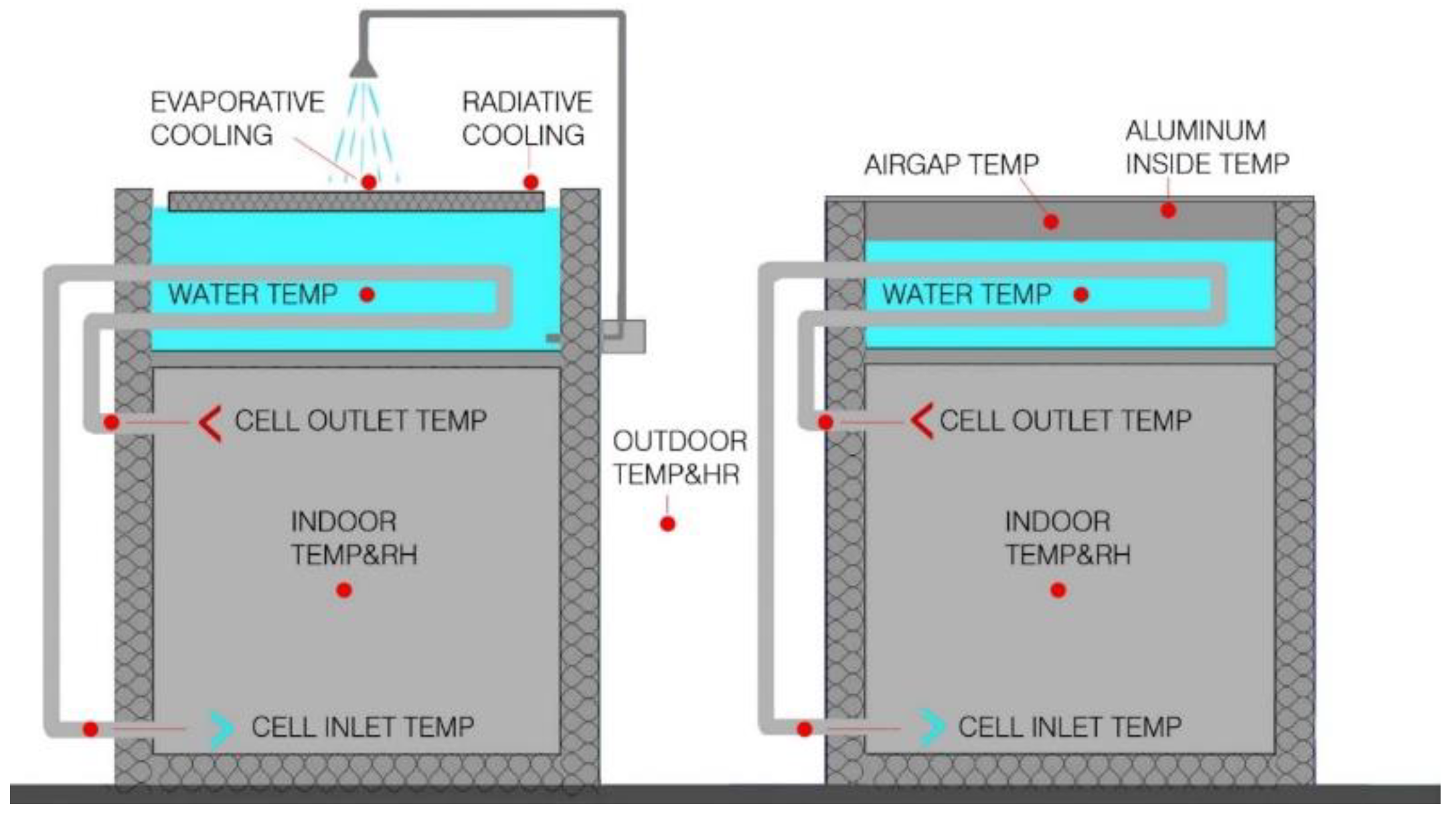
Figure 5.
Green roof connected to a WAHE (a); detail of the WAHE (b).

Figure 6.
Photo of the testing unit with an insulated roof pond and nighttime spraying (a); scheme showing the system operation (b).
Figure 6.
Photo of the testing unit with an insulated roof pond and nighttime spraying (a); scheme showing the system operation (b).
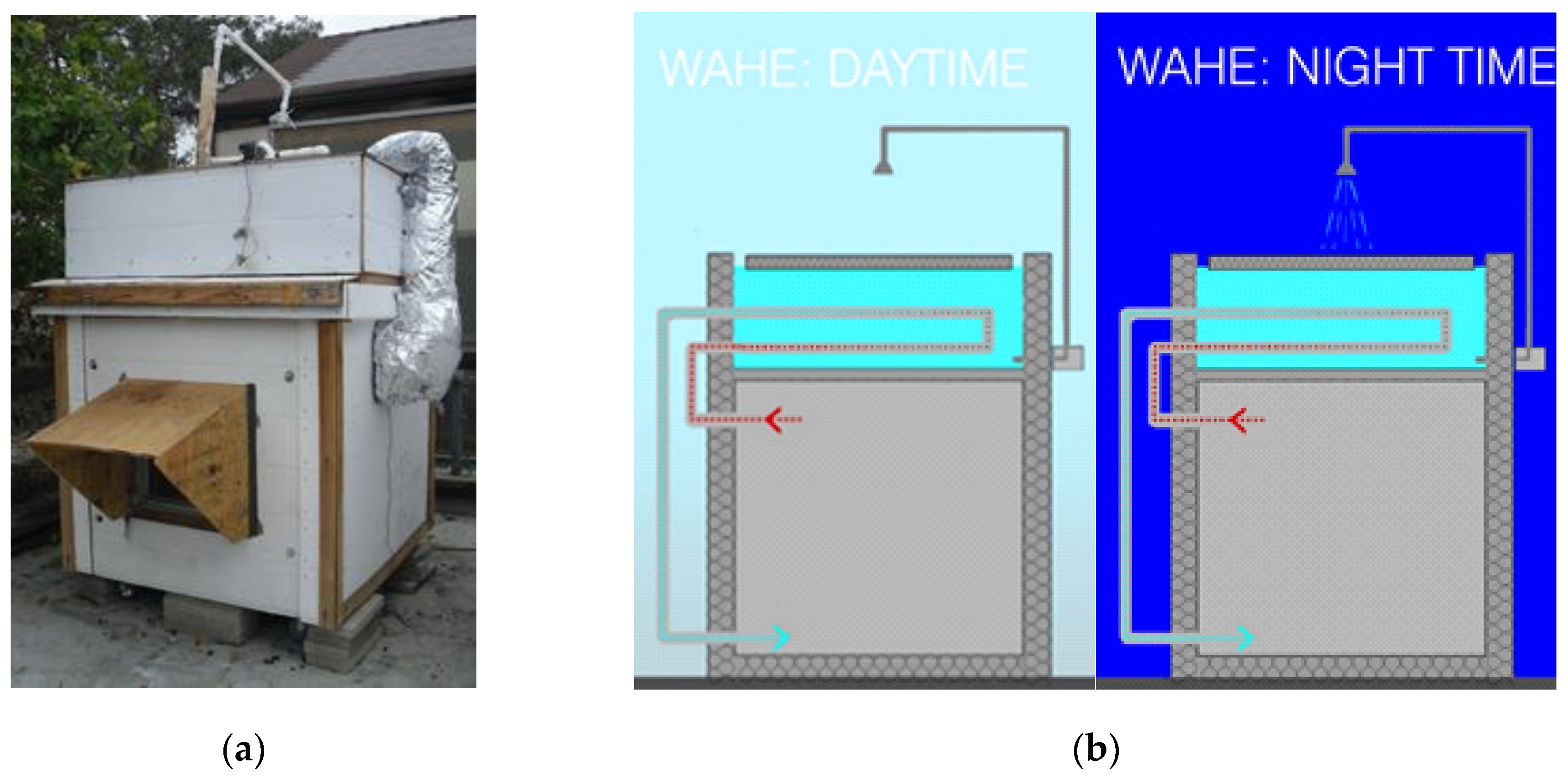
Figure 7.
Experimental testing unit with a roof pond sealed by an aluminum sheet (a); detail of the WAHE (b).
Figure 7.
Experimental testing unit with a roof pond sealed by an aluminum sheet (a); detail of the WAHE (b).
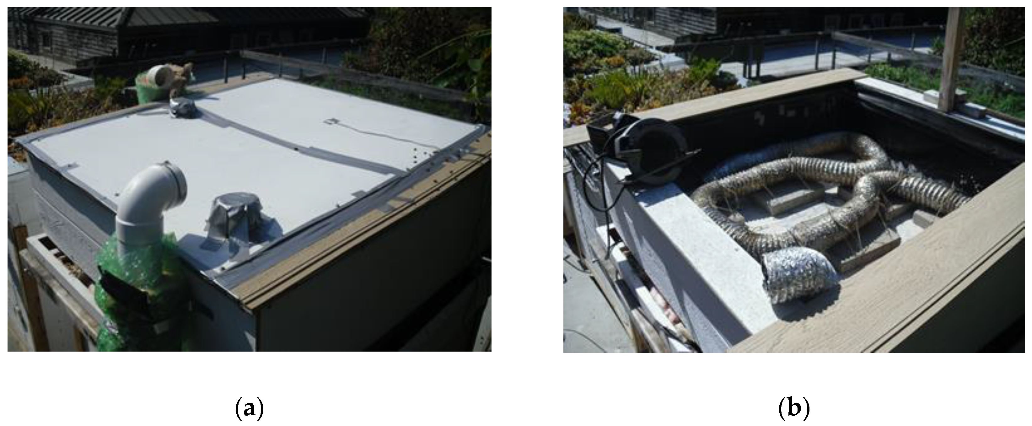
Figure 8.
Temperature recorded over a period of four days in a green roof without WAHE.
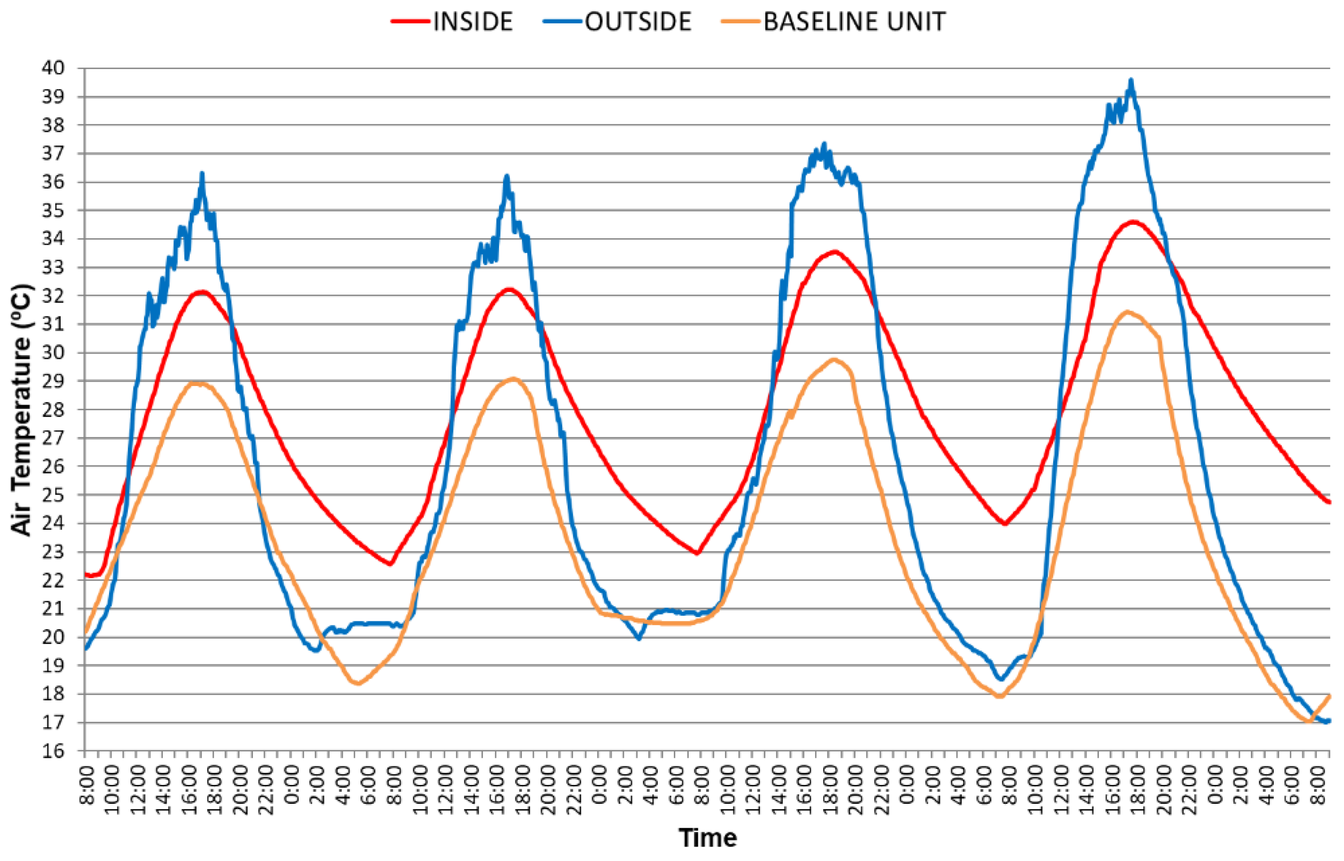
Figure 9.
Temperature recorded over a period of four days in a green roof with WAHE.
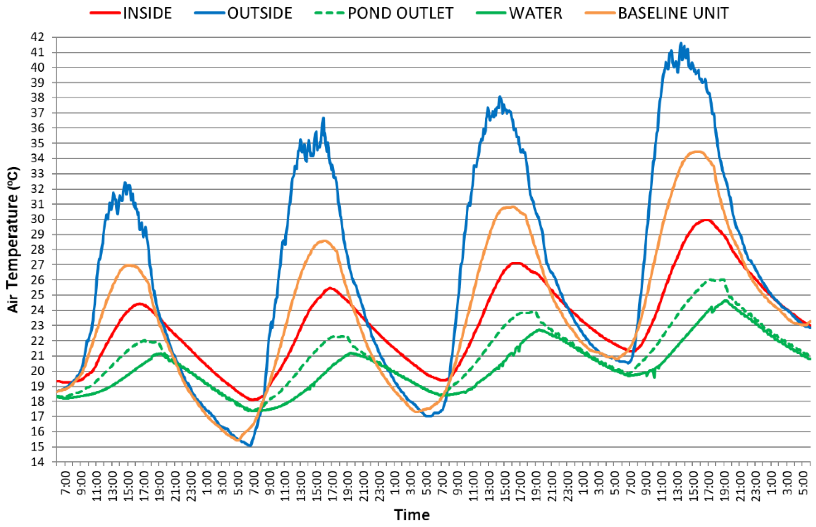
Figure 10.
Temperature recorded over a period of four days in a roof pond covered with insulation and nighttime spraying without WAHE.
Figure 10.
Temperature recorded over a period of four days in a roof pond covered with insulation and nighttime spraying without WAHE.
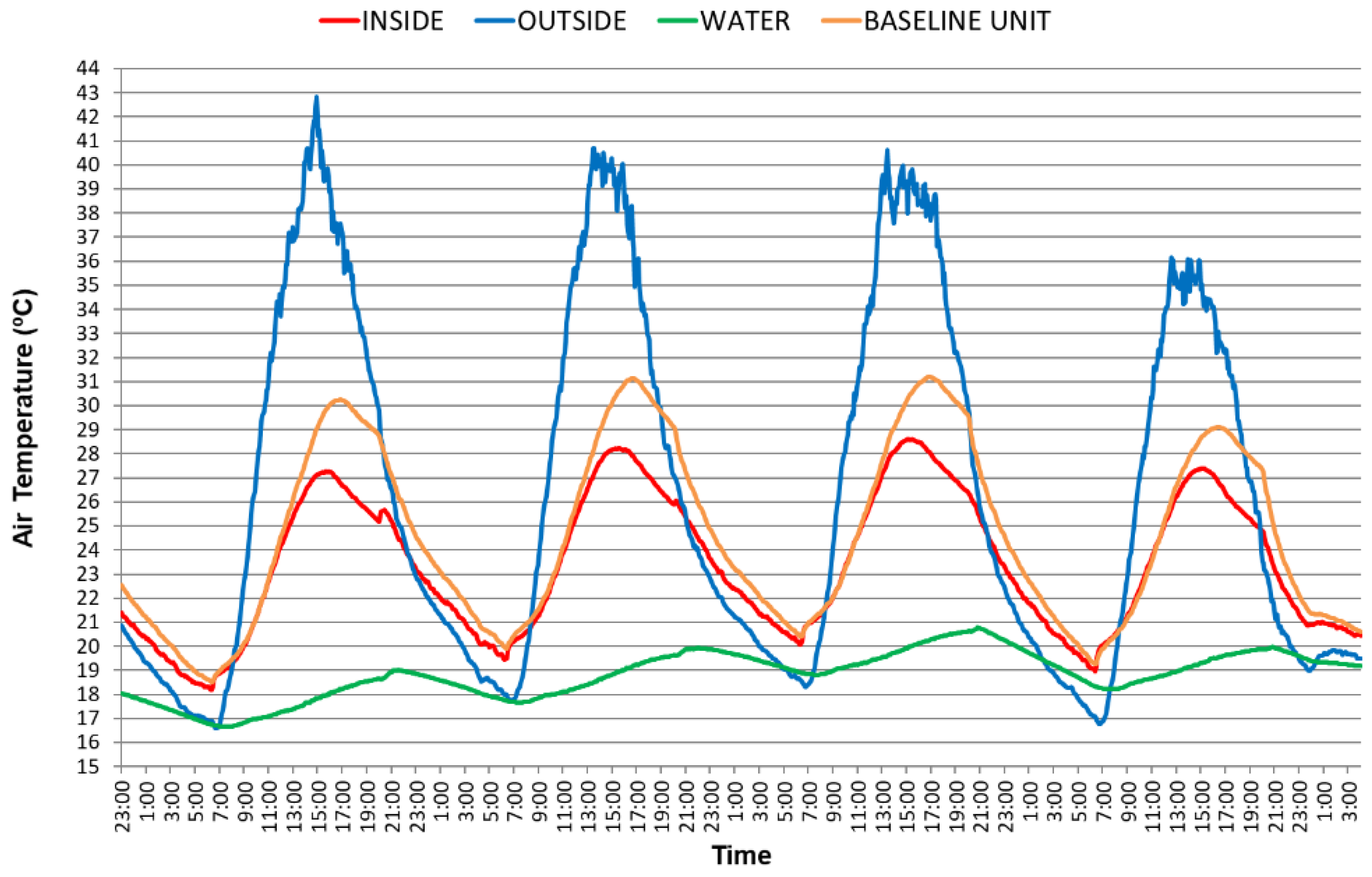
Figure 11.
Temperature recorded over a period of four days in a roof pond covered with insulation and nighttime spraying with a water to air heat exchanger.
Figure 11.
Temperature recorded over a period of four days in a roof pond covered with insulation and nighttime spraying with a water to air heat exchanger.
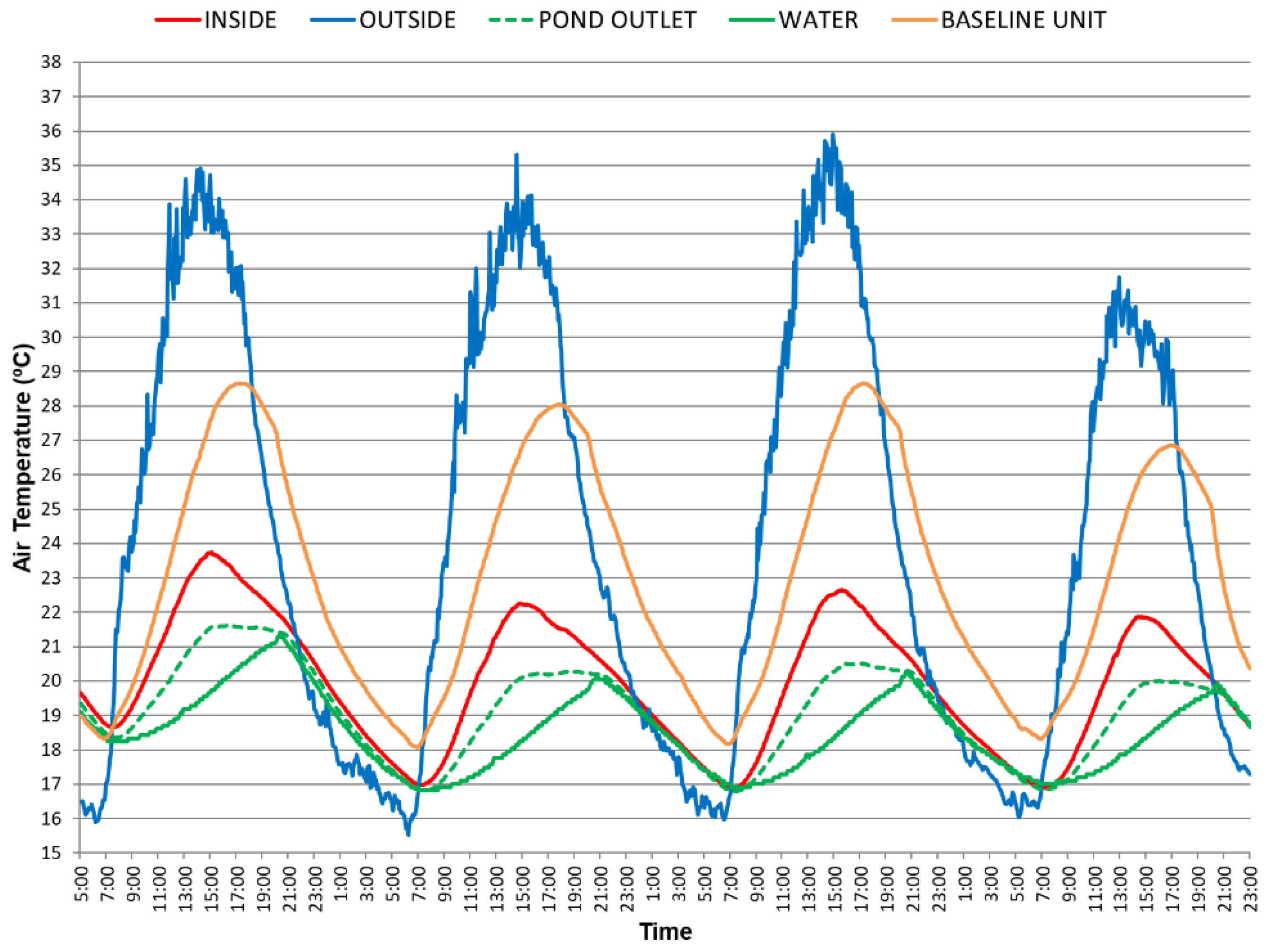
Figure 12.
Temperature recorded over a period of four days in a roof pond sealed by an aluminum sheet without WAHE.
Figure 12.
Temperature recorded over a period of four days in a roof pond sealed by an aluminum sheet without WAHE.
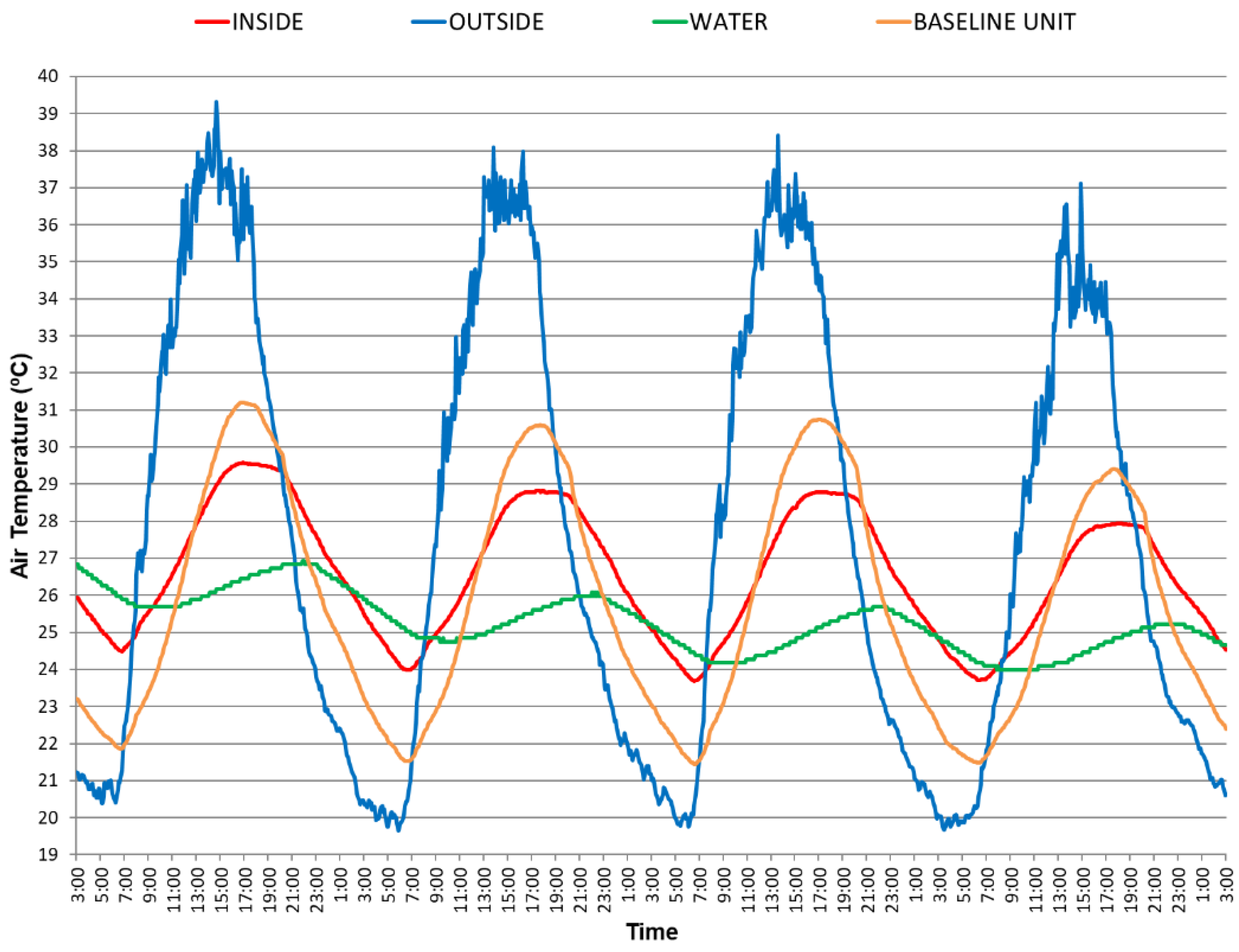
Figure 13.
Temperature recorded over a period of four days in a roof pond sealed by an aluminum sheet with WAHE.
Figure 13.
Temperature recorded over a period of four days in a roof pond sealed by an aluminum sheet with WAHE.
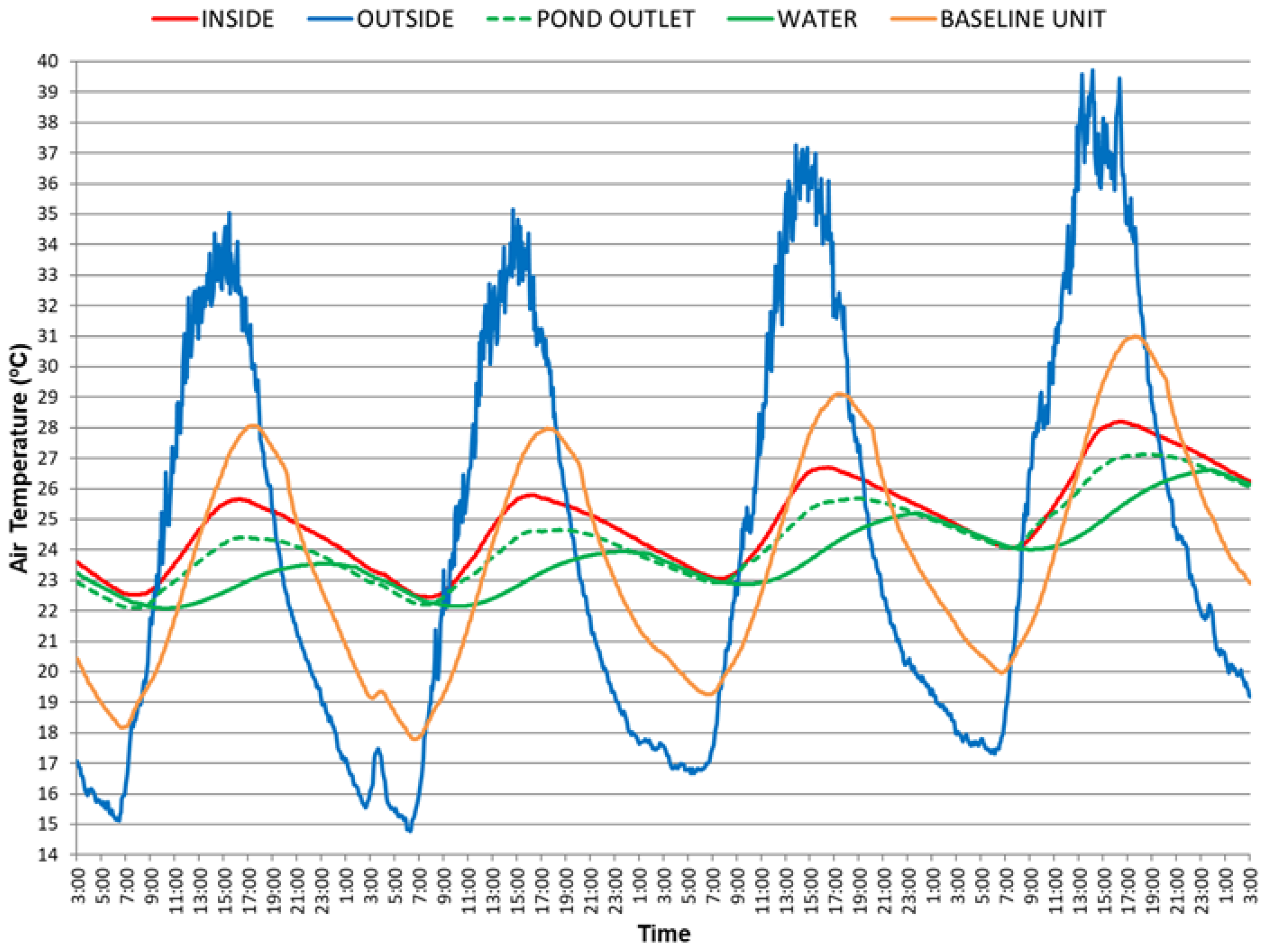
Figure 14.
Comparison between the daily TDR performance and the daily swing of ambient temperature in the baseline unit and all roof variants. The WAHE is operating.
Figure 14.
Comparison between the daily TDR performance and the daily swing of ambient temperature in the baseline unit and all roof variants. The WAHE is operating.
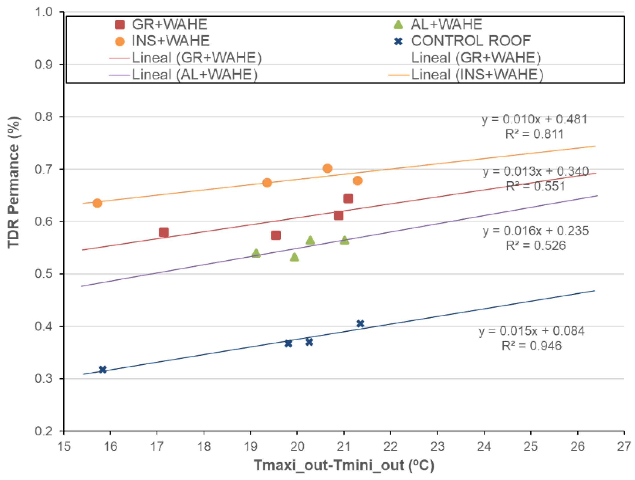
Figure 15.
Comparison between the daily TDR performance and the daily thermal swing in the green roof (GR) and the baseline unit when the WAHE is on and off.
Figure 15.
Comparison between the daily TDR performance and the daily thermal swing in the green roof (GR) and the baseline unit when the WAHE is on and off.
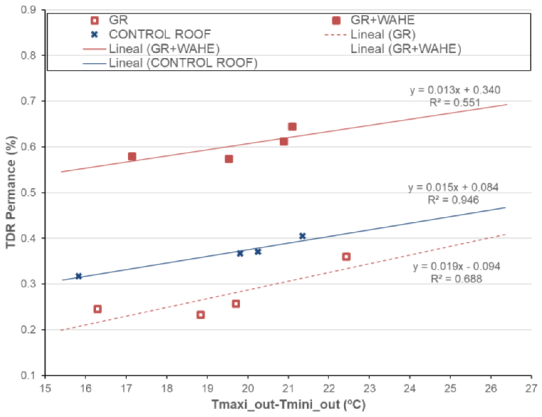
Figure 16.
Comparison between the daily TDR performance and the daily thermal swing in the insulated roof pond (INS) and the baseline unit when the WAHE is on and off.
Figure 16.
Comparison between the daily TDR performance and the daily thermal swing in the insulated roof pond (INS) and the baseline unit when the WAHE is on and off.
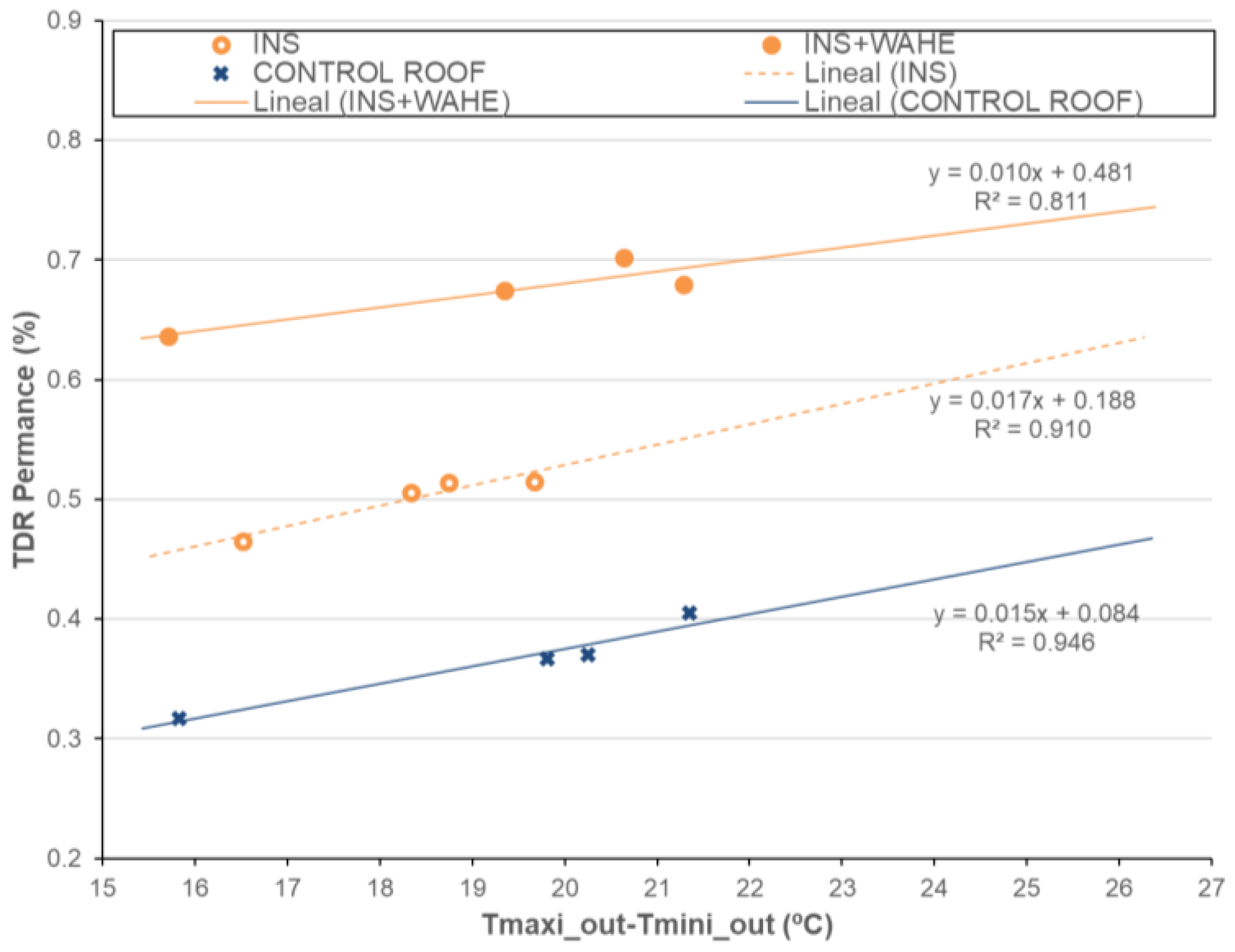
Figure 17.
Comparison between the daily TDR performance and the daily thermal swing in the roof pond sealed with an aluminum sheet (AL) and the baseline unit when the WAHE is on and off.
Figure 17.
Comparison between the daily TDR performance and the daily thermal swing in the roof pond sealed with an aluminum sheet (AL) and the baseline unit when the WAHE is on and off.
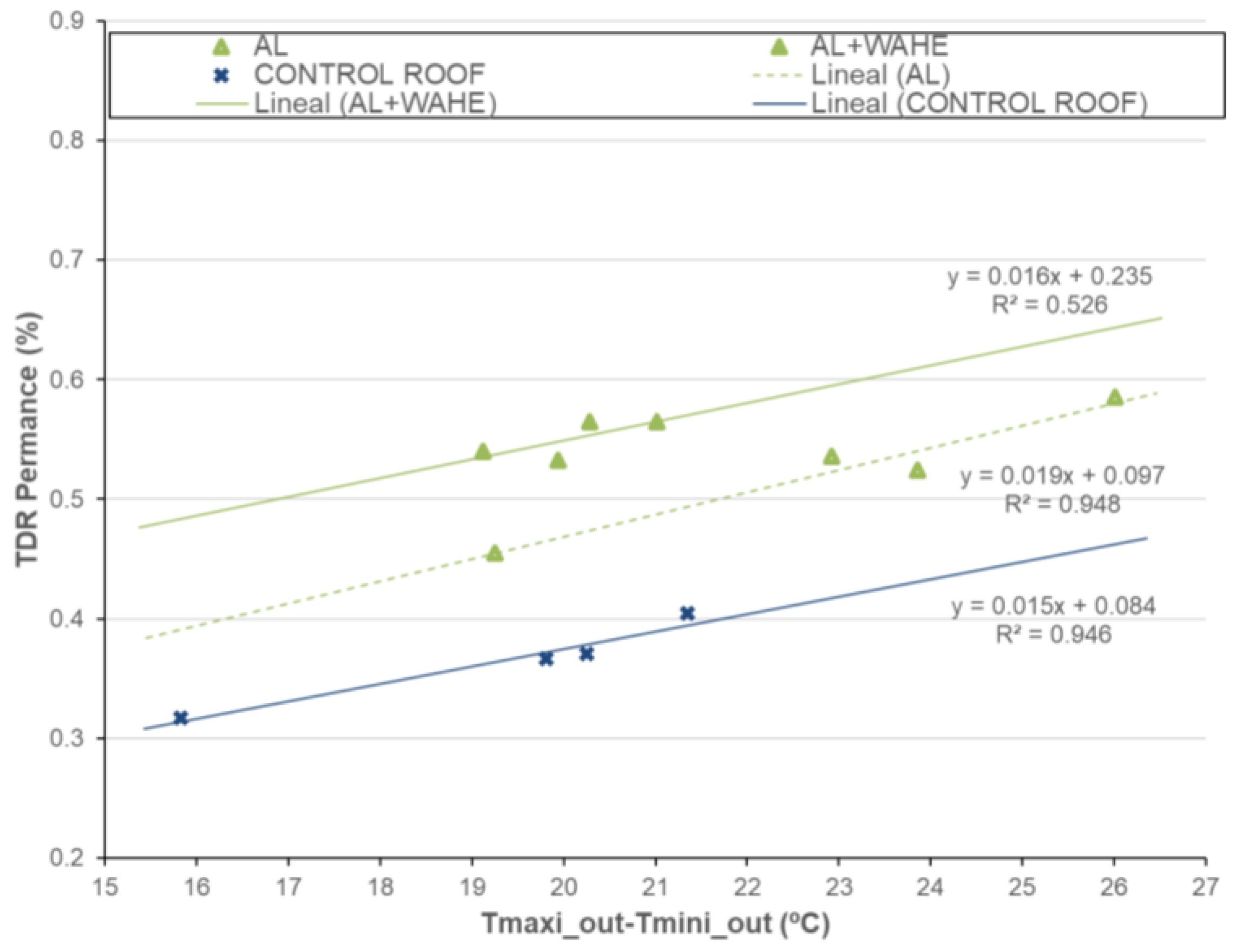

Table 1.
Layers of the experimental testing unit and their thermal properties.
| Material | mm | W/mK | W/m2K | |
|---|---|---|---|---|
| Green roof | soil | 130 | 0.610 | |
| gravel | 20 | 2.000 | ||
| waterproofing | 1 | 0.210 | 0.282 | |
| metal plate | 2 | 44.00 | ||
| OSB | 11 | 0.130 | ||
| fiberglass | 21 | 0.044 | ||
| XPS | 127 | 0.043 | ||
| gypsum board | 11 | 0.180 | ||
| Insulated roof pond | polystyrene | 30 | 0.033 | |
| water | 300 | 0.591 | ||
| waterproofing membrane | 1 | 0.210 | 0.272 | |
| metal plate | 2 | 44.00 | ||
| Aluminum roof pond | aluminum sheet | 1 | 0.610 | |
| air gap | 100 | 0.233 | ||
| water | 200 | 0.591 | 1,311 | |
| waterproofing membrane | 1 | 0.210 | ||
| metal plate | 2 | 44.00 | ||
| Baseline unit roof | metal plate | 1 | 44.00 | |
| waterproofing membrane | 1 | 0.21 | ||
| OSB | 11 | 0.130 | ||
| air gap | 38 | 0.233 | 0.306 | |
| XPS | 140 | 0.043 | ||
| gypsum board | 11 | 0.180 | ||
| Wall section | gypsum board | 10 | 0.180 | |
| fiberglass | 89 | 0.044 | ||
| OSB | 11 | 0.130 | ||
| vapor-barrier | 1 | - | 0.308 | |
| XPS | 51 | 0.043 | ||
| air gap | 13 | 0.079 | ||
| laminated wood | 5 | 0.130 |
Disclaimer/Publisher’s Note: The statements, opinions and data contained in all publications are solely those of the individual author(s) and contributor(s) and not of MDPI and/or the editor(s). MDPI and/or the editor(s) disclaim responsibility for any injury to people or property resulting from any ideas, methods, instructions or products referred to in the content. |
© 2025 by the authors. Licensee MDPI, Basel, Switzerland. This article is an open access article distributed under the terms and conditions of the Creative Commons Attribution (CC BY) license (http://creativecommons.org/licenses/by/4.0/).
Copyright: This open access article is published under a Creative Commons CC BY 4.0 license, which permit the free download, distribution, and reuse, provided that the author and preprint are cited in any reuse.


