
Submitted:
11 February 2025
Posted:
11 February 2025
You are already at the latest version
Abstract
This paper explores the extension of the IEEE 802.15.4 standard for wireless process control, focusing on its application in industrial environments where secure and efficient data transfer is critical. The study addresses the limitations of existing industrial wireless protocols like ISA100 Wireless and Wireless HART, particularly their inability to fully support wireless control loops. A new approach is proposed, integrating state-of-the-art microcontrollers and transceivers to design a robust wireless control network (WCN) that ensures low latency and interference resistance. Key developments include the design and production of a custom development board, comparative analyses of hardware and software components, and the implementation of the TSCH (Time Slotted Channel Hopping) operating mode. The paper validates the solution through simulations and practical experiments, demonstrating its capability to maintain stable control loops in challenging industrial settings. Results indicate that the proposed network meets stringent industrial requirements, paving the way for broader adoption of wireless technologies in process control. This work highlights the feasibility of overcoming existing barriers to wireless control in industrial applications, contributing to the development of cost-effective and reliable systems.
Keywords:
wireless process control
; time slotted channel hopping
; industrial wireless networks
; embedded systems
; industrial automation
1. Introduction
Cost optimization has been, is and will be a priority in any field, whether we refer to products or services. Through the continuous release of new technologies on the market, we can experience those opportunities that, until recently, were not accessible to everyone. The development of new technologies is driven primarily by novel ways in which the costs of producing/delivering products/services need to be reduced. A recent example is the first commercial flight into space [1], which opens the door to new opportunities for humanity. This could not have been achieved without cost optimization, either by using emerging technologies or by re-using different components [2].
Wireless communication is also on the long list of emerging technologies. Aggressively adopted in the last decade, it allows us to transmit a greater amount of data, faster and over much greater distances in real time. Any device on the market incorporates at least one wireless technology, whether we are talking about Wi-Fi, Bluetooth or others. Moreover, cost optimization and the emergence of new technologies meant the availability of smart and cheap devices known as the Internet of Things or Industrial Internet of Things for industry. The industrial community has been more reluctant to adopt wireless technologies, especially in process control. Wireless technology is seen as unstable and unpredictable for data transfer in an industrial process [3,4]. In recent years, this has undergone a major change with the emergence of the IEEE 802.15.4 standard [5] and its amendments that allow the secure and efficient transfer of data in an environment where this is critical, such as in an industrial environment.
The availability of this standard has triggered the release on the market of wireless communication protocols specifically designed to be used in industrial environments. As examples, we can mention ISA100 Wireless (mostly adopted in the USA) [6] and Wireless HART (mostly adopted in Europe) [7] which mainly allow the monitoring of industrial processes. Industrial process control, although it is mentioned in the technical specifications of the two standards, refers to the transmission over wireless of the setpoint rather than the command. This area has been identified as appropriate to carry out the research activities described in this paper. Two case studies immediately benefit from this new concept: an industrial process in which the controller and process are at a significant distance from each other, and inside a satellite where one of the methods of reducing production costs and sending it into space is to reduce the number of wires between equipment.
2. Related Work
A cautious approach to using wireless communication in industrial control loops is to use it only for transmitting the process output. This approach limits delays and increases robustness, which wireless communication can introduce to the execution of the control loop. In [8], the authors use the Wireless HART communication protocol to transmit the process output to the controller. They observed that the wireless device sends data to the controller randomly. This leads to system instability, as the controller sends commands to the process at well-defined intervals. Consequently, the introduction of a Kalman filter in the control loop was proposed to eliminate noise and a state estimator to calculate the process output when it is not transmitted by the wireless device. The study concludes that by incorporating these improvements into the control loop, the differences compared to a classic wired PID controller are minor.
The topic addressed in this article is not new, as the specialized literature contains a series of studies that have experimented with similar ideas. The results and conclusions of these experiments provide a good foundation for our research activities. Wireless transmission of commands and outputs is used in [9], where the Wireless HART industrial communication protocol is employed to control the flow rate in an industrial process. Like the ISA100 Wireless protocol, it is based on the IEEE 802.15.4 standard to define the physical layer. In the study, the output is transmitted wirelessly to a PID controller at intervals of 15 seconds. Due to the controller’s sampling period being different (1 second), a problem arises in generating correct and optimal commands. The authors propose two potential solutions to address this issue: using the last received measurement for command calculation or employing a state estimator to calculate the measurement when it is not updated wirelessly. The results show that the control system stabilizes at different reference values when the measurement is unavailable. Additionally, the authors conclude that the Wireless HART protocol is not recommended for fast process control, as it has data transmission intervals on the order of seconds. Using state estimators and the last received command ensures system stability in situations where measurements are not received, or the wireless network is inactive. Some studies utilize open-source or proprietary software tools to simulate the behavior of a wireless network controlling an industrial process, focusing on latency, delays, and overlaps with other communication protocols. In [10], the authors use OMNET++ [11] to simulate the behavior of a wireless control network (WCN) based on the Wireless HART protocol. Using OMNET++, the authors achieved a comprehensive network simulation considering the factory layout, transmission power, and frequency hopping. The simulation results highlight the impact of delays and packet error rates on process shutdown times. Depending on these parameters, shutdowns can range from 1 hour (low error rate) to 40 hours (high error rate). The authors conclude that simulating a wireless network helps process engineers optimally define the physical network architecture and the placement of sensors and actuators in the field. The latency and delays caused by the Wireless HART network significantly affect industrial processes. A different approach is described in [12], where the authors chose to implement missing functionalities of the Wireless HART protocol to manage a control loop. Within the protocol’s framework, the device attached to the process cannot independently send messages to the device attached to the controller but responds to a request from the controller. All these messages pass through a gateway that limits the time for command transmission and measurement reception and introduces processing delays. To demonstrate the reliability of the customized implementation of the Wireless HART protocol, comparative studies were conducted regarding transfer times with the Foundation Fieldbus protocol [13]. The results were promising, showing that wireless control can be as reliable as wired control. Minimum sampling periods of 500 milliseconds were achieved, primarily limited by the Wireless HART protocol. As a conclusion, the authors made several recommendations for modifying the protocol to more efficiently manage control loops. There are studies that use the physical layer defined by the IEEE 802.15.4 standard in conjunction with custom implementations of upper layers to develop WCNs. One such example is [14], where the authors use multi-hop wireless communication to control an inverted pendulum. The hardware support used is similar to the one employed in our research activities. In this study, the Low-power Wireless Bus protocol [15] was used to transmit commands and measurements between the controller and the process. Using this protocol, relevant performance was achieved in controlling the inverted pendulum, specifically: maximum variations of 3 degrees in position and 25 centimeters in the pendulum's base travel, with sampling periods of 100 milliseconds or less.
Following the assessment of existing solutions in the literature regarding the use of wireless communication in industrial process control, the following observations were made:
- Most solutions used existing wireless communication protocols, specifically ISA100 Wireless or Wireless HART.
- Applications using wireless communication focus primarily on monitoring and data collection from sensors, with less emphasis on control.
- Both mentioned protocols effectively address monitoring; however, the control aspect is problematic as resulted from the conclusions of the assessed papers.
- Delays and limitations regarding data transmission periods were observed, which can cause instability in industrial process control.
- Some studies implemented additional functionalities to the standards to eliminate or at least mitigate the effects of these delays.
- The authors of these papers conclude that using wireless communication in a control loop is possible but not recommended for fast processes.
Based on the conclusions, this article approaches the issue from a different perspective: development begins with a well-established standard for industrial wireless communication (i.e., IEEE 802.15.4-2020), leveraging its existing functionalities. The control loop implementation was carried out without making significant changes to the standard. To limit the delays caused by wireless technology, a development board was designed using mature components available on the market. The article exhibits the use of the latest technologies in the field of embedded systems and industrial wireless communications to develop and validate an innovative method of industrial process control. The continuous evolution of these technologies in recent years and the increased interest in smart embedded devices has laid the foundations for convincing premises for carrying out research activities that have helped to define the following objectives: analysis of the industrial protocols already available on the market, definition of the requirements for the implementation of a wireless network for industrial process control, choosing the best options of microcontroller and wireless transceiver for control, the production of a development board used for validating the solution and the actual implementation of the WCN.
2. Materials and Methods
Work methodology follows a sequential approach by dividing the research activities into three main stages: 1) the selection of the state-of-the-art hardware and software resources needed to implement the WCN. This stage uses as input the authors’ experience in industrial wireless networks, the requirements for implementing a WCN resulted from the analysis of existing industrial wireless standards and protocols, and the findings and conclusions from related work and literature; 2) the design and implementation of the development system used further on to implement, test and validate the WCN and; 3) the actual implementation and deployment of the WCN.
2.1. Hardware and Software Resources
The first stage defines what are the necessary requirements for a WCN and performs a comparative study between two families of microcontrollers that focuses on the available functionality, the operating frequency, the amount of flash memory and RAM, the number of communication interfaces as well as the current consumption in the different operating modes. To assess the functionality of microcontrollers, a hardware abstraction layer has been developed: it will be possible to access this functionality using the same function headers in the programming language. For wireless transmission, three wireless transceivers were compared in terms of consumption, data transfer speed and modulation. Following the comparative study of wireless standards, a set of requirements necessary for the implementation and correct operation of a WCN emerged. These requirements were used as references for choosing compatible microcontroller and transceiver families. The comparative study of microcontrollers and transceivers resulted in the choice of microcontroller and transceiver used in the software implementation of the control network alongside the software needed for implementation.
The following objectives have been set for this stage:
- Identification of the requirements necessary for the proper operation of a WCN
- Identifying the hardware support for the deployment of the WCN
- Identifying the software support for the implementation of the WCN. To achieve objectives, the use of the latest hardware and software technologies available on the market was chosen.
- The identification of the hardware and software support of the WCN has been done using literature, comparative studies between different technologies, component manufacturers and available software solutions.
2.2. Development System Design
The second stage includes the manufacturing of the development board as a result of software and hardware design. The developed hardware and software components will be detailed, as well as the result of the functionality, consumption and wireless transmission tests. The general consumption of the whole board, the microcontroller, the transceiver configured in different power modes, the amplifier and the sensors were tested and validated. Wireless communication distance tests were also carried out between two development boards.
For this stage, the following objectives were set:
- Identifying the hardware components of the development system
- Design of the development board used for the development of the WCN
- Production of at least two development boards
- Power testing and validation of the development board functionalities
The hardware components of the development board were chosen based on price, functionality and availability in the semiconductor market, which at the time of research activities, was affected by a global crisis. For the design of the development board, electronic schematics offered free of charge by component manufacturers were partially used. The hardware abstraction layer aims to eliminate the dependency of the software implementation of the wireless control network on specific hardware components. The principle of abstraction and focus on common elements and functionalities available on microcontrollers and transceivers has been adopted.
2.3. The Wireless Control System
The third stage exposes the steps that the implementation of the WCN has gone through from a software point of view. The implementation of the IEEE 802.15.4-2020 standard, which was the basis on which the implementation started, as well as the changes made to the functionality of the standard to comply with the requirements of a WCN, will be presented. Previous studies have identified the software and hardware platforms on which the WCN will be implemented. Considering all the requirements for the proper operation of a WCN, the following objectives have been set:
- Implementation of the functionality required for the TSCH (Time Slotted Channel Hopping) mode of operation of the wireless network, as defined by the IEEE 802.15.4-2020 standard.
- Allocation of communication slots for devices associated with the network.
- Time synchronization of devices associated with the network.
The implementation of the WCN started from the IEEE 802.15.4-2020 standard, which was used as a reference. An attempt was made to develop as few proprietary functionalities as possible and to perform minimal customization of the standard to support a WCN. The software development environment was the latest version of the STM32CubeIDE application offered free of charge by STMicroelectronics, which at the time of the research activities was 1.17.0. The latest versions of the software support packages for the STM32L4 microcontroller family, 1.18.1 were also used. The source code developed in this study was stored in the GitLab versioning system, the latest version available being 17.6.2. The validation of the correct operation of the control loop was done using the PicoScope 2204A oscilloscope with which the speed setpoint values for the control loop were generated and the process output was measured.
3. Wireless Control Network Requirements
The use of wireless technologies in industrial process control is a novelty, most communication protocols in the industrial field and not only, are used for monitoring: reading the process parameters and sending them to a central unit for display. In [16], three wireless protocols were presented, two used in home automation applications and one in industrial applications, each with its own particularities. A brief comparative table of the features offered is shown in Table 1.
Bearing in mind that the topic of the paper is the design of a wireless network for control, a set of requirements in this regard will be presented below, such as:
- The wireless network will be designed in such a way as to allow control of both slow and fast processes. From a process point of view, a latency below 100 milliseconds is required.
- The latency between two nodes in a wireless network with a mesh topology is dependent on the number of levels between the two nodes. Thus, if a control loop is desired using two nodes in the network, those two nodes must communicate directly without the communication link being handled by the network coordinator. The wireless network must support point-to-point communication between any two nodes.
- Redundancy is needed to guarantee continuous process control if the wireless communication between the node measuring the process output and the node calculating the command no longer works properly. Current wireless protocols only provide redundant routes through router nodes.
- Interference can cause the control loop to operate incorrectly. Using an operating frequency less common in wireless communication, such as 868 MHz, along with frequency hopping, minimizes this risk and maximizes noise resistance.
- A high data transfer speed is recommended to ensure low latency.
- Time synchronization between wireless network components must be accurate. Desynchronization leads to incorrect operation of the control system.
4. Design of the Development System
4.1. Microcontroller
During the research activities, the most recent variant of a dedicated core for microcontrollers released by Arm was the Cortex-M4. Consequently, for the comparative study, microcontrollers from two families utilizing these cores were selected: the STM32L4 family from STMicroelectronics and the MSP432 family from Texas Instruments. This section will present a comparative study between the two families of microcontrollers, taking one representative from each side: STM32L432KC [17] from the STM32 family and MSP432P401R [18] from the MSP432 family. Arm provides manufacturers of microcontrollers based on the Cortex core with a set of templates to standardize access to core components, peripherals as well as microcontroller initialization. This makes it much easier to use a new microcontroller and migrate the code to other microcontrollers. Using CMSIS (Cortex Microcontroller Software Interface Standard) [19], manufacturers can provide users with a standard set of header files for describing microcontroller components. To access the functionality of the microcontroller and the communication interfaces, a so-called hardware abstraction layer has been defined and developed so that higher layers are independent of the hardware part. It contains a set of functions that have the same syntax for all supported microcontrollers. The hardware abstraction layer contains a series of modules that access most of the microcontroller components such as: configuration and control of the system clock, control of pins, communication interfaces, timers, analog-to-digital and digital-to-analog converters, etc. Microcontroller modules are generically numbered, for example, from HAL_GPIO_0 to HAL_GPIO_X for GPIO modules where X is the maximum number of modules.
The microcontroller families that are considered for WCN design are STM32L4 from STMicroelectronics and MSP432 from Texas Instruments. As representative microcontrollers we have chosen STM32L432KC and MSP432P401R, each of them having development boards available on the market. Next, a series of comparisons between the two chosen microcontrollers are presented in Table 2 in terms of performance, consumption, and available features.
According to the aforementioned table, the two microcontrollers exhibit comparable performance, power consumption, and interfaces. The STM32L432KC microcontroller operates at double the frequency of the MSP432P401R, which enhances processing times, such as those required for command calculations performed by the controller. The availability of STM32L432KC in packages smaller than MSP432P401R helps reduce the size of the development board. To ensure synchronization and the lowest possible power consumption, the microcontroller must have the ability to be woken up from low power mode at specific points in time, with the lowest possible resolution. The MSP432P401R microcontroller can only be woken up from low power mode by the RTC module, which can be set to a minimum of one second, which is quite a lot for a control system. The STM32L432KC microcontroller can be woken up from low power mode by a timer operating in low power mode. It uses a precise external crystal as the clock source which can wake up the microcontroller at intervals of a minimum of 30.51 microseconds. Overall, the STM32L432KC microcontroller, or an equivalent from the SMT32L4 family, was chosen as the support for the development board and the design of the WCN. The design and development of the wireless network can be done in the STM32CubeIDE environment available free of charge and maintained by STMicroelectronics. The documentation and support for the chosen microcontroller is clearly superior to those from Texas Instruments.
4.2. Transceiver
This subchapter will present the radio transceivers that are being considered for the design of the development board that will be further used for the development of the wireless monitoring and control network. For each transceiver, a driver has been developed that allows access to the available features: accessing registers, reading and writing frames, measuring the quality of the received signal, selecting the antenna and managing interrupts. Each of the radio transceivers has a communication interface with the microcontroller that has several components:
- A serial communication interface that is typically SPI.
- A pin used by the transceiver to generate interrupts and thus notify the microcontroller that a state change has occurred.
- A reset pin through which the microcontroller resets the transceiver – the internal registers are set to their default values.
- Optionally, a pin through which the microcontroller sets the transceiver to low power mode.

Table 3.
Feature comparison between wireless standards.
| Transceiver | Microchip AT86RF212B | Texas Instruments CC110L | STMicroelectronics S2-LP |
| Frequency bands (MHz) | 779 – 787 863 – 870 920 – 928 915 – 930 |
300 – 348 387 – 464 779 – 928 |
430 – 470 860 – 940 |
| Modulations | BPSK O-QPSK |
2-FSK 2-GFSK 4-FSK 4-GFSK OOK MSK |
2-FSK 2-GFSK 4-FSK 4-GFSK OOK ASK |
| Data rate (kbps) | 20 ÷ 1000 | 0.6 ÷ 600 | 0.1 ÷ 500 |
| Sensitivity (dBm) | -100 | -95 | -101 |
| Maximum power (dBm) | +11 | +12 | +16 |
| Power increment (dBm) | 1 | Variable | 0.5 |
| Consumption | |||
| Sleep (nA) | 200 | 200 | 950 |
| Idle (µA) | 450 | 1700 | 420 |
| RX (mA) | 9.2 | 14.6 | 8.6 |
| TX (mA) | 26.5 @ +10 dBm | 30 @ +10 dBm | 11 @ +10 dBm |
| FIFO length (bytes) | 128 | 64 | 128 |
| Operating temperature | -40 ÷ +85 | -40 ÷ +85 | -40 ÷ +105 |
| RSSI | X | X | X |
| Antenna diversity | X | - | X |
| CCA | X | X | X |
| IEEE 802.15.4 | X | - | X |
| ETSI EN 300 220 | X | X | X |
4.3. Development Board
Synchronizing devices within a WCN over time is crucial, particularly in the context of industrial process control. An initial attempt involved utilizing a commercially available development board equipped with crystals or precise oscillators (with frequency drift below 10 parts per million), which yielded acceptable results. Consequently, to improve stability, the decision was made to design and implement a custom development board that would fulfill the specific requirements of a wireless control system.
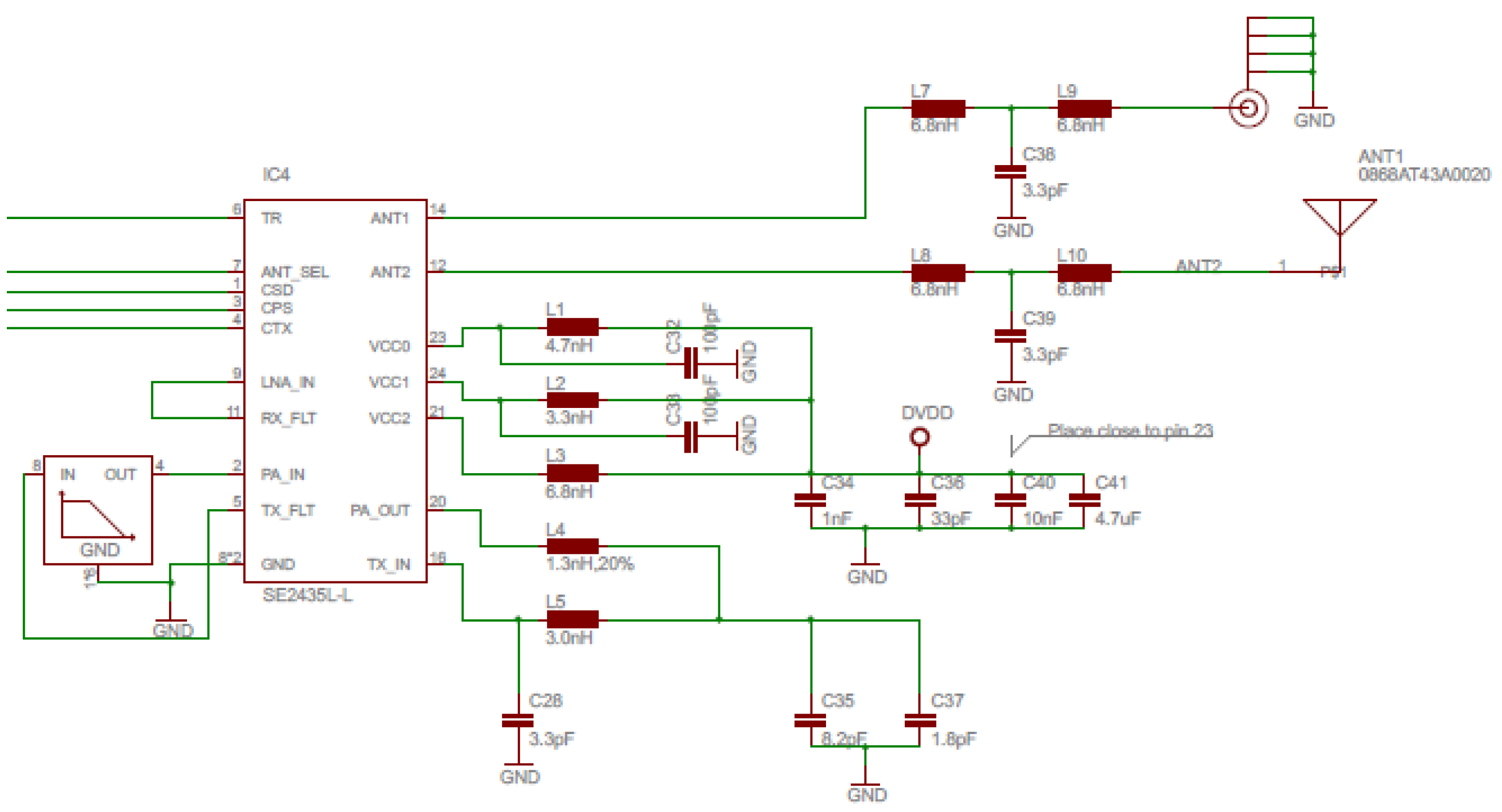
A prior stage concluded that the implementation of the WCN should involve the use of a microcontroller from STMicroelectronics' STM32L4 family. The STM32L462RE, a low-power high-performance microcontroller, was identified as the optimal choice due to its 512 KB of flash memory, 160 KB of RAM, and an array of peripherals including analog-to-digital converters, digital communication interfaces, and timers. Additionally, a comparative analysis was conducted between two transceivers: the S2-LP from STMicroelectronics and the AT86RF212B from Microchip. The findings indicated that Microchip's transceiver is preferable with respect to power consumption and adherence to the IEEE 802.15.4-2011 standard. To comply with ETSI EN 300 220, which regulates the maximum transmission power level at 27 dBm or 500 mW, the development board will integrate a power amplifier. The Skyworks SE2435L amplifier, operating within the 860-930 MHz frequency band, provides 28 dBm amplification and a maximum output power of 31.5 dBm.
Two environmental monitoring sensors are utilized on the development board: the SHT21 temperature sensor from Sensirion and the CCS811 CO2 and TVOC sensor from Ams. Both sensors are connected to the microcontroller via I2C interfaces. The sensors are positioned at one end of the development board to minimize any influence from the other active components, particularly in terms of temperature.
The hardware abstraction layer provides access to the hardware components of the microcontroller, including the clock system, pin configuration, timer configuration, digital communication interfaces (UART, SPI, I2C), and memory access. Utilizing a hardware abstraction layer enables the developed application to be easily ported to another microcontroller, regardless of whether it includes an Arm Cortex core. This approach ensures the software application's independence from the physical layer.
Since the development board was designed to be used in Europe, the software design was designed in such a way as to comply with the ETSI EN 300 220 standard for sub-GHz wireless communication. Thus, in the 863 – 870 MHz operating band we have three possible transmission power limits:
- 25 mW or 14 dBm in the K, L, M, N, O, and R bands
- 500 mW or 27 dBm in the P-band
- 5 mW or 7 dBm in the Q band
For all frequency bands, the polite spectrum access mode will be used, i.e. the radio module will be in the reception for a period of at least 160 μs, to detect possible transmissions in progress. If there is no transmission in progress, the transmission of the data frame will commence.
Figure 1 illustrates the general architecture of the development board where the central component is the microcontroller, to which other components are connected: the radio part on the right side with outputs on SMA and SMD antennas, the sensors and unused pins of the microcontroller on the side, and the micro-USB and JTAG connectors on the left side.
The development board's core module is the STM32L462RE microcontroller in a 64-pin LQFP package (IC6). Figure 2 shows the power supply for the microcontroller via 4 pairs of VDD/VSS pins and filtering capacitors for the 3.3V supply voltage. The microcontroller's clock is provided by a 32768 Hz oscillator (X6) and a 24 MHz piezoelectric crystal (X5) with charging capacitors. Access to the internal bootloader for loading the firmware is achieved through the JP10 jumper, which is linked to the BOOT0 pin. On the right side of the microcontroller, there are connections to the transceiver via the SPI interface (pins R_MOSI, R_MISO, R_SCLK, and R_SS), the debugging interface (pins JTAG_TRST, JTAG_TDO, JTAG_TDI, JTAG_TCK, and JTAG_TMS), as well as the unconnected I2C1, I2C2, UART1, and UART2 communication interfaces for flexibility. The connections to the control pins for the transceiver, the CO2 sensor, and the LEDs are also visible.
Figure 3 shows the wireless transceiver (IC2) along with auxiliary circuits. The X2 crystal provides the clock signal for the transceiver to generate the transmission frequency. On the right side of the transceiver are the pins for SPI communication with the microcontroller, as well as the transceiver control pins: R_RST (reset), R_IRQ (interrupt request), and R_SLP (sleep mode).
Figure 6.10 shows the wiring diagram of the Skyworks SE2435-L power amplifier (IC4), which can boost the transceiver's transmit power to 27 dBm.
Figure 4.
Power amplifier wiring schematic.
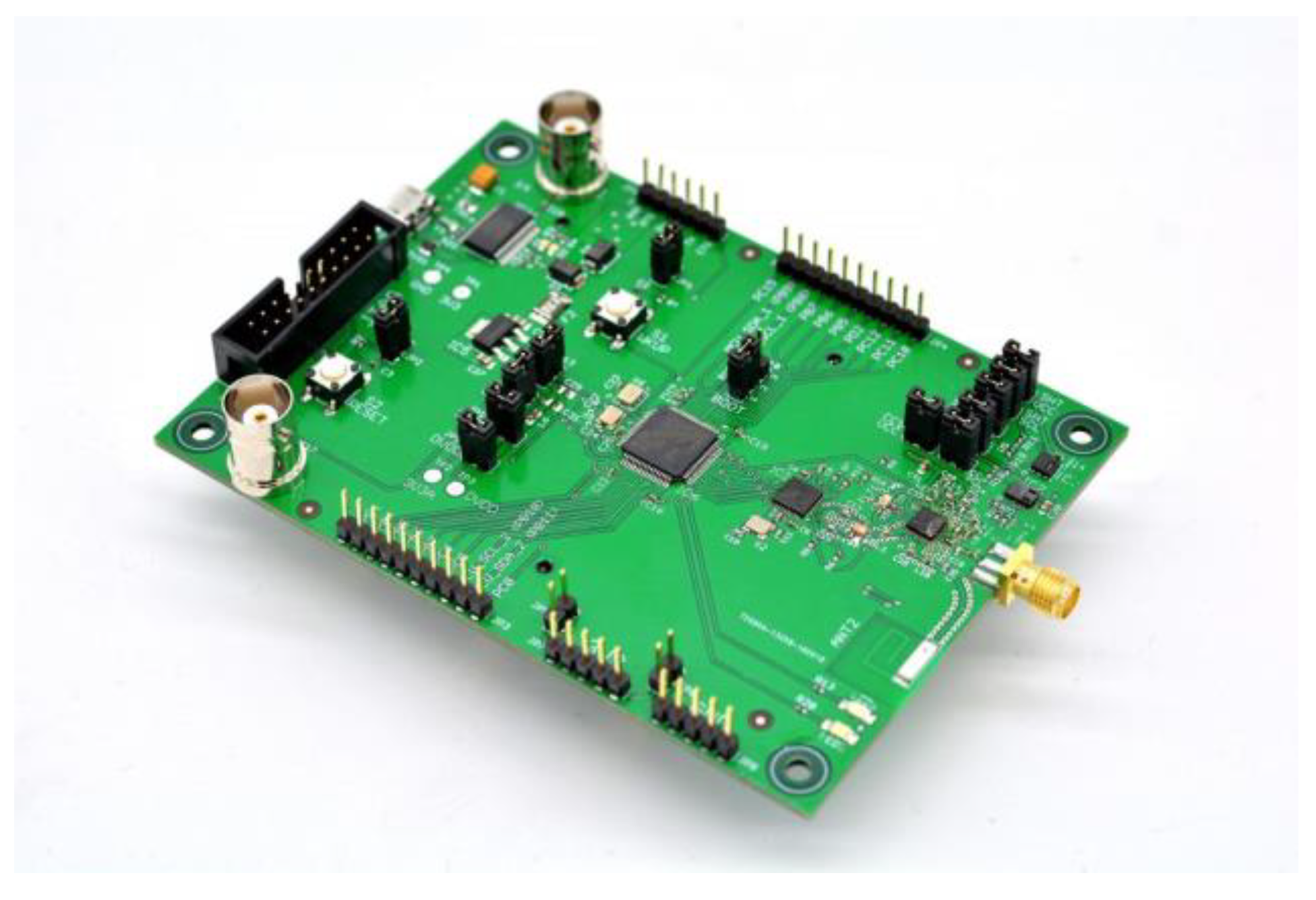
The initial step of the functionality test was to verify the correct operation of the power supply using the three available options: power supply via the USB port, power supply via the TTL-3v3 serial cable, and power supply via the batteries mounted on the back of the board. Using a test program that changes the state of an LED, the correct power supply of the board was validated.
Figure 5.
The development board.
The programming of the microcontroller was tested using the JTAG connector, utilizing both the JTAG and SWD protocols. This process was carried out successfully using STMicroelectronics' ST-LINK Utility as well as through the STM32CubeIDE development environment. The clock source part was tested by initializing the 24 MHz crystal and the 32768 Hz oscillator properly. Two timers were used with the clock sources, set to the microcontroller frequency and the 32768 Hz oscillator respectively, to generate pulses on two external pins. A logic analyzer measured the pulses to verify if the clock sources were functioning correctly. The correct operation of the microcontroller modules intended for use in the WCN development—such as GPIO, timers, communication interfaces, ADC, etc.—was verified. The wireless component's functionality was confirmed by checking the communication between the microcontroller and transceiver via the SPI interface, involving reading and writing registers. Transmission and reception tests were conducted using a commercial transceiver development board as a benchmark. It performed correctly after a minor hardware adjustment to fix an incorrect filter connection on the board. The transmission power was measured with a spectrum analyzer, varying it over a wide range, both with and without the amplifier on the board.
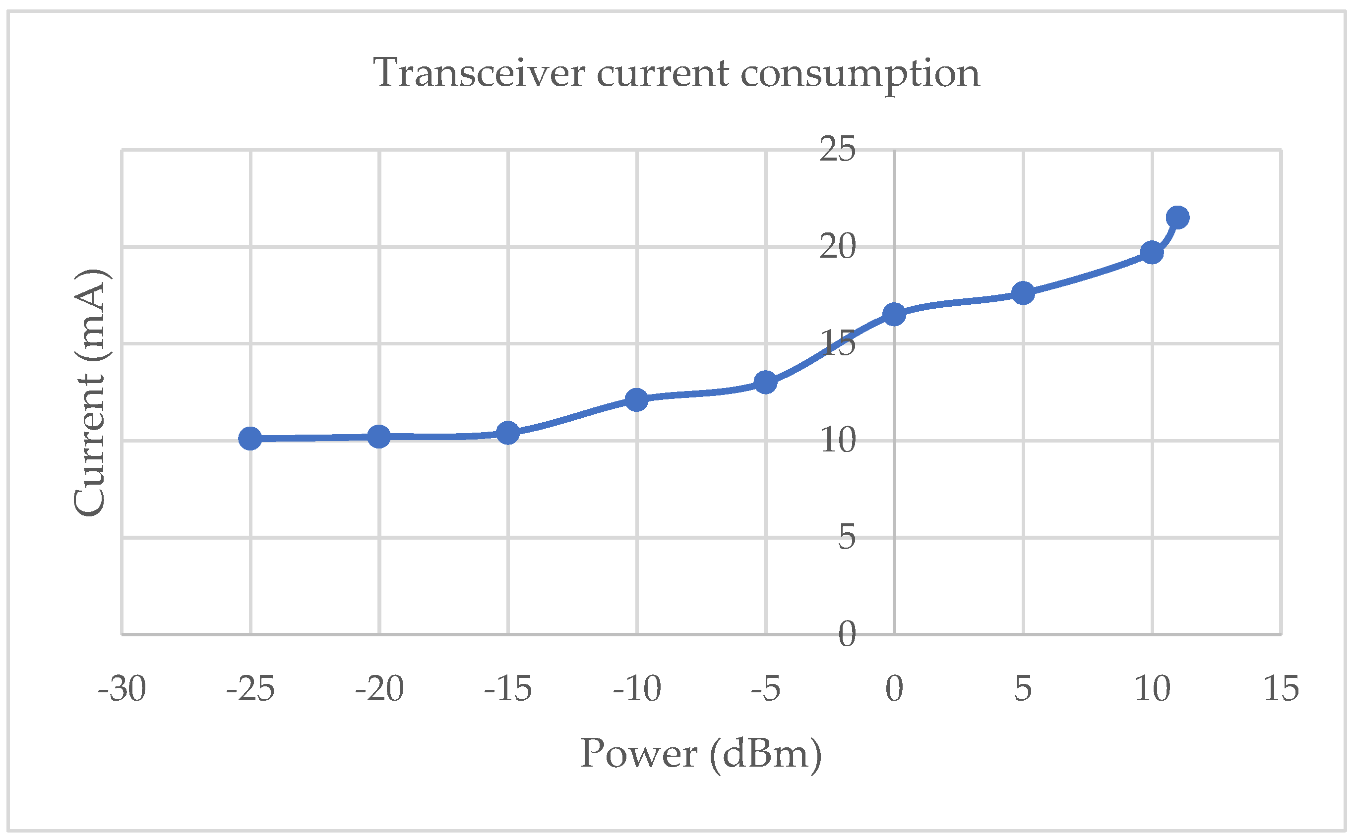
The power consumption of the microcontroller was assessed in two operational modes significant for wireless network implementation: running (RUN mode) and low power consumption (STOP2 mode). With a 3.3V power supply, the measured current consumption values were as follows: 8.42mA in RUN mode and 2.05µA in STOP2 mode. Additionally, the power consumption of the transceiver was evaluated across all operating modes, including transmission, reception, idle, and low power consumption. Using the test application, the transceiver was configured for each of these modes, yielding the following current consumption measurements:
Figure 6.
Transceiver current consumption.
At 3.3V supply voltage, the amplifier provides +22 dBm for the 868 MHz European frequency band. The Table 5 below shows the amplifier's consumption in low power, bypass, reception, and transmission modes and Figure 7 details the consumption at different power settings.
Radio transmission was tested at various power levels, measuring signal quality (RSSI) and packet transmission error over a 4 km distance. Results are shown in Figure 8.
All three transceivers support the European frequency band 863 – 870 MHz, which aligns with our requirements, as well as compliance with the European standard ETSI EN 300 220 [21] for devices operating in the frequency range of 25 – 1000 MHz. Each transceiver is compatible with modulation schemes endorsed by the IEEE 802.15.4 standard, specifically O-QPSK, 2-FSK, and 4-FSK. The data transfer speeds are adequate to maintain brief air time, ensuring effective wireless control. The sensitivity levels of the transceivers are comparable, approximately -100 dBm, and their transmission power is sufficient. Regarding power consumption, the STMicroelectronics transceiver is notably efficient, drawing only 11 mA at +10 dBm transmission power, which is about three times less than the other transceivers. All transceivers support the Clear Channel Assessment (CCA) functionality mandated by ETSI EN 300 220. Additionally, a common driver has been developed to facilitate the operation of these transceivers.
5. Implementation of the Wireless Control Network
5.1. Wireless Control Network Topology
A star network topology was selected to facilitate the implementation and validation of wireless communication in a control loop. The network coordinator is on the first level, and the second level contains wireless devices that have a direct connection to the network coordinator. Figure 9 displays the network topology, with the coordinator represented by the green circle and the wireless devices shown by blue circles. Wireless communication between the coordinator and each device is represented by broken blue lines. The interrupted orange lines indicate possible control loops between two devices, with one acting as a controller and the other as a process. A control loop can be established between any two wireless devices associated with the network. The coordinator configures the control loop based on user commands.
The software implementation of the WCN utilized several development boards from STMicroelectronics, specifically those based on the STM32L series. Figure 10 provides a detailed overview of the hardware components employed and their interconnections. The ATZB-212B-XPRO extension, which is built on Microchip's AT86RF212B transceiver, facilitates wireless communication and is connected to various development boards through SPI and GPIO interfaces.
The software implementation of the WCN coordinator was divided into three modules to simulate the links between the different levels in the OSI model. The physical layer and data link have been implemented on the NUCLEO-L432KC and ATZB-212B-XPRO pair, referred to as backbone in the literature. The application layer was implemented on a NUCLEO-L476RG board, which offers sufficient processing power and memory to respond quickly to wireless device associations within the network. This board transmits relevant information about the wireless network (including paired devices and messages sent and received) to a desktop application running on a computer for user-friendly viewing. From this desktop application, users can configure and initiate a control loop by selecting the wireless device that will function as the controller and the one that will act as the process. For the control loop, the implementation involved the NUCLEO-L152RE development board paired with the ATZB-212B-XPRO extension. One of these pairs serves as the controller: it receives the setpoint applied to an external pin and, using the measurement received from the process, calculates the command to be applied. The command is then received by the second pair, connected to a NUCLEO-F767ZI development board, which simulates the process. The command is applied to the process through an output of the DAC module, and the measurement is read via an input of the ADC module. The reference is applied as a voltage to one of the pins of the NUCLEO-L152RE board. The output of the process, along with the measurement, is captured and displayed on an oscilloscope to validate the correct operation of the control loop.
5.2. Physical Layer
The software implementation of the physical layer began with the development of the driver for the AT86RF212B transceiver. The functionalities of the physical layer were implemented in two components: PLDE (physical layer data entity) and PLME (physical layer management entity), each having a corresponding .h and .c file. The PLDE module contains the necessary functions to initialize and control the transmission and reception operations of the transceiver:
- PLDE_Init - used to initialize the transceiver and in turn calls the AT86RF212B_Init function.
- PLDE_Idle - used to set the transceiver to idle mode (TRX_OFF). In this way, the transceiver consumes the least current. This mode is used when the transceiver does not have to receive or transmit data frames.
- PLDE_Transmit - used to pass a data frame. The parameters of the function include the data to be transmitted and its size.
- PLDE_Receive - used to set the transceiver to receive mode.
- PLDE_ComputeRSQI - used to calculate the quality of the received signal. It can have a value between 0 and 31.
- PLDE_Interrupt - called every time the transceiver changes its state. Depending on the new status, some operations are required. The transceiver signals a state change by setting the IRQ pin to high. This function calls the functions in the upper layer (the data link layer) that retrieve the frames received by the transceiver.
The PLME module contains the functions for reading and writing the attributes of the physical layer. The module also contains the definition of the PIB attributes attached to the physical layer. The physical layer can be configured by writing PIB attributes:
PLME_Init - initializes the attributes of the physical layer with the default values.
PLME_Read - used to read an attribute of the physical layer, regardless of its type.
PLME_Write - used to write an attribute of the physical layer, regardless of its type.
Non-configured devices, associated devices, and the network coordinator transmit data frames only on shared or dedicated timeslots. To avoid collisions and coexist with other radio users, the TSCH CCA access method is used. This method requires any device wishing to transmit a frame to first scan for ongoing transmissions. If an ongoing transmission is detected, the device will wait until the next shared or dedicated timeslot to attempt transmission. Figure 11 shows the flow for transmitting a data frame in TSCH CCA mode.
5.3. Data Link Layer
The IEEE 802.15.4-2020 standard defines only one sub-layer of the data link layer, which is the MAC sub-layer. The features of the MAC sub-layer are implemented in three modules: MLME (MAC Layer Management Entity), MLDE (MAC Layer Data Entity), and primitives. Primitives are functions that implement operations executable by the MAC sub-layer. Only those primitives ensuring the correct operation of the wireless network in TSCH (Time-Slotted Channel Hopping) mode have been implemented. The MLME module includes the read and write functions for attributes of the data link layer. Additionally, this module contains the definition of PIB attributes associated with the data link layer. The data link layer can be configured by writing to the PIB attributes:
- MLME_Read – used to read an attribute of the data link layer, regardless of its type
- MLME_Write – used to write and attribute of the data link layer, regardless of its type
The MLDE module contains the functions needed to generate the data frames, parse received data frames and notify the application layer when a new frame has been received:
- MLDE_GenerateBeacon – used to generate a beacon frame and gets as input the beacon frame parameters and the payload.
- MLDE_GenerateData – used to generate a data frame and gets as input the payload on the type of link on which the frame will be sent.
- MLDE_GenerateCommand – used to generate a command frame and gets as input the type of command and the payload.
- MLDE_GenerateAck – used to generate an acknowledgement frame.
- PLDE_FrameInication - notifies the application layer that new frame has been received. This function extracts the useful data from the frame and sends it to the application layer.
- PLDE_ErroIndicate – used by the physical layer to notify the data link layer that and error occurred while receiving a frame.
- PLDE_FramConfirm – used by the physical layer to notify the data link layer that a new frame has been received successfully.
- MLDE_IncommingFrame – used by the data layer to extract and analyze the data contained in each received frame and perform the necessary actions.
5.4. Inter-Layer Communication
To further scale the control network, the application layer of the network coordinator was deployed on a separate microcontroller from the one used for the physical and data link layers. This separation allows the application layer to be easily transferred to a more powerful device, thereby enabling the management of a larger number of wireless devices. Communication between the two devices, where one implements the application layer and the other handles the physical and data link layers, is facilitated via UART. A minimal inter-layer communication protocol has been established for this purpose. The structure of the data framework defined in the IEEE 802.15.4-2020 standard served as a source of inspiration for this protocol:
- Start frame delimiter (SFD)
- Payload data size
- Sequence number
- Primitive identifier
- Primitive parameters
- Checksum
Figure 12.
Inter-layer data frame.
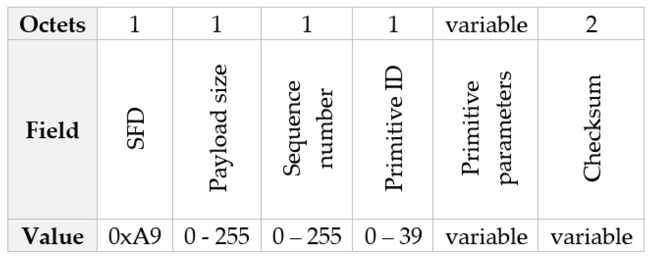
Receiving a byte with the value 0xA9 indicates the start of a data frame to the recipient device. If a byte with the value 0xA9 appears in the payload, it is replaced by bytes 0xA8 0x57, and a byte with the value 0xA8 is replaced by bytes 0xA8 0x58. The primitive identifier indicates the type of primitive being transmitted over the UART. The identifier for each type of primitive is listed in Table 6.
In the table above, the primitives used in inter-layer communication are highlighted in green. The checksum calculation uses the CRC-16-CCITT algorithm as specified in the IEEE 802.15.4-2020 standard for data frame transmission.
5.5. Time Management
Synchronization between wireless devices connected to the network and the network coordinator is essential for the proper operation of control loops. Consequently, both the design of the development board used for the software implementation of the control network and the commercially available development boards employ precision oscillators to measure time accurately. These oscillators, which offer an accuracy of up to 20 parts per million (ppm), enable a time lag of less than one millisecond between wireless devices within a superframe. To minimize the time discrepancy between devices, a superframe interval comprising 6000 ten-millisecond timeslots was selected, resulting in the superframe repeating every minute. The development boards, whether commercial or developed through the research activities outlined in this article, typically feature two types of oscillators/crystals for time measurement. The first type is a low-precision crystal with an oscillation frequency in the MHz range, primarily used for generating the microcontroller's clock frequency. This crystal can also serve as a frequency generator for certain timers. The second type, often seen as an oscillator, has a low oscillation frequency (usually 32,768 Hz) and high accuracy (below 20 ppm), making it suitable for precise time measurement. Only specific timers on the microcontroller utilize this crystal as a frequency generator. Taking into account these two types of oscillators/crystals, their typical frequencies and accuracy, along with the wireless data transfer rates supported by the transceiver, a timeslot duration of 10 milliseconds was chosen, synchronized every 50 timeslots or 500 milliseconds. Within each timeslot, two-way communication between two wireless devices can occur. Within each set of 50 timeslots, there are four types of timeslots, as illustrated in Figure 13.
The first timeslot in the group of 50, or timeslot 0 marked with A, is an advertisement timeslot. During this timeslot, the network coordinator sends a beacon frame over the wireless network to notify other wireless devices of the network's presence. The beacon frame also includes information about the exact time when the coordinator transmitted the frame. Odd timeslots are control timeslots, marked with C, used in control loops to transmit data frames containing commands and process measures. These timeslots occur every 20 milliseconds, so the sampling period used in the control loop must be 20 milliseconds. Even timeslots are management timeslots, marked with M, used by the coordinator to pass settings to wireless devices, as well as by wireless devices to pass data to the coordinator. Shared timeslots, marked with S, are utilized by all wireless devices participating in the network to transmit frames when they do not yet have assigned timeslots. These timeslots are used in procedures such as associating a wireless device with the network, where the last step is to allocate dedicated timeslots. The 25th timeslot in the group of 50 will always be the shared timeslot. In a superframe, there are 120 advertisement timeslots, 2760 management timeslots, 3000 control timeslots, and 120 shared timeslots.
The IEEE 802.15.4-2020 standard defines a timing template (macTimeslotTemplate) that must be followed by every transmission and reception over wireless. Figure 14 illustrates a two-way communication between two wireless devices, the first being the initiator of communication.
A timeslot is defined as the interval between T0 and T8, with a standard duration of 10 milliseconds. According to the transmission template, the actual data frame transmission commences at T2, which, as per the standard, is 2120 microseconds from the start of the timeslot. To ensure correct reception, the second wireless device will enter reception mode earlier, specifically at T1, which is 1020 microseconds from the beginning of the timeslot. The device will then wait for the interval between T3 and T1 for the transmission to begin, i.e., 2200 microseconds. The moment T4 signals the completion of the data frame's transmission/reception. Subsequently, the receiving device will send an acknowledgment frame to the transmitting device exactly after T6 - T4, which is 1000 microseconds. The first device will enter reception mode at T5 and wait for the acknowledgment frame's transmission until T7. The end of the transmit/receive process for the acknowledgment frame and the conclusion of bidirectional communication are marked by T8.
Strict adherence to the transmission and reception pattern is essential for the proper functioning of the WCN, particularly in the time synchronization between wireless devices. Time synchronization occurs between the coordinator, which acts as the time source, and each wireless device associated with the network. For this purpose, the beacon frame is used, which the coordinator transmits in the first timeslot of the group of 50 timeslots. Figure 14 illustrates a synchronization procedure between two wireless devices, with the top one being the coordinator and the bottom one being a wireless device that is associated with or joining the network.
At time T1, the wireless device enters receive mode and awaits the transmission of the beacon data frame. At time T2, in accordance with the transmit and receive template, the coordinator initiates the transmission of the beacon data frame. By time T3, the coordinator has completed the transmission, and concurrently, the wireless device completes its reception of the frame. Subsequently, the device processes the frame by extracting time-related information, including the superframe and the specific fraction of a second when the transmission started. At time T4, the wireless device updates its timeslot and timeslot group timers, each consisting of 50 timeslots. Consequently, at time T5, the wireless device will generate an interrupt to indicate the commencement of the next timeslot, thereby maintaining synchronization with the network coordinator.
5.6. Starting the Network
The user triggers the start of the WCN via the desktop application. The coordinator communicates with the application through a UART connection. The command to start the wireless network is received by the application layer of the coordinator that signals the state machine (Figure 15) to start the wireless network.
The first step is to reset all the PIB attributes of the application and data link layer to the default values. This is done through the MLME-RESET primitive: the application layer calls the MLME_ResetRequest function and the data link layer, after completing the reset operation, calls the MLME_ResetConfirm function.
The second step is to scan the radio space. Through scanning, the aim is to identify all available wireless networks and detect the noise level on each channel supported by the physical layer. The radio space scanning operation is done using the MLME-SCAN primitive, initially in passive scan mode and then in ED (energy detect) mode on each channel. The application layer calls the MLME_ScanRequest function, and the data link layer calls the MLME_ScanConfirm function after the scan operation is complete. The result of the scan will be a list of detected wireless networks that contain information about each network, such as: the identifier, the channel used, the noise level on each channel, the short or extended address of the coordinator, and the signal quality. For the wireless network to be started, the channel with the lowest detected noise level and a different network identifier than the network identifiers of the active wireless networks are chosen.
The next step is to set the parameters of the wireless network using the MLME-SET primitive. The application layer sets the short address of the coordinator as a random number in the range 1 – 65535, the channel on which the wireless network will run, and the network identifier which will also be a random number in the range 1 – 65535. The extended address of the coordinator is fixed and set by the transceiver manufacturer. Wireless network parameters are defined as the PIB attributes of the physical and data link layers. To set them, the application layer calls the MLME_SetRequest function each time you want to set a PIB attribute. The data link layer will respond by calling the MLME_SetConfirm function after setting the PIB attributes.
The second last step is to start the wireless network using the MLME-START primitive. The application layer calls the MLME_StartRequest function, and the application layer responds by calling the MLME_StartConfirm function.
The last step is to switch the application network operating mode to time slotted channel hopping (TSCH) mode. This is achieved by means of the MLME-TSCH-MODE primitive. The TSCH mode is started from the desktop application by the user. The command is received by the application layer, which will call the MLME_TschModeRequest function, and the application layer will respond by calling the MLME_TschModeConfirm function. Switching to this mode of operation will start the slotframe and timeslot timers. In TSCH mode, the coordinator will transmit beacon data frames every 500 milliseconds, containing information about the wireless network.
5.7. Joining the Network
A wireless device is associated with the WCN by going through the operations specified in Figure 16 that details the message flow between the master and wireless device data link layers.
The first step is to switch the wireless device's transceiver to receive mode using the MLME-RX-ENABLE primitive. Thus, the wireless device will be able to receive the beacon frames transmitted by the wireless network coordinator(s). The application layer of the wireless device calls the MLME_RxEnableRequest function, and the data link layer of the wireless device responds by calling the MLME_RxEnableConfirm function. From each receiving beacon data frame, the wireless device will extract useful information about the wireless network: network identifier, coordinator address, time in seconds, and fraction of a second. With this data, the wireless device will be able to synchronize over time with the network coordinator and continue the association procedure.
The second step is to start the TSCH operating mode. This will be done after synchronizing in time and will start the timers of the timeslot and slotframe. The application layer will call the MLME_TschModeRequest function, and the application layer will respond by calling the MLME_TschModeConfirm function.
The third step is the actual association to the wireless network. This is done using the MLME-ASSOCIATE primitive. The application layer will call the function MLME_AssociateReqest which will command the data link layer to pass a command data frame – association request. This frame contains information about the wireless device, such as the extended address and capabilities. The data link layer of the coordinator acknowledges the reception of this data frame by passing an acknowledge data frame. The coordinator data link layer calls the MLME_AssociateIndication function to notify the application layer of the receipt of a join request. The application layer will extract information about the wireless device, and if the controller has the necessary resources, it will allow the device to be associated with the network by assigning it a short address. Subsequently, the MLME_AssociateResponse function will be called to notify the data link layer of the result of the association operation, which in turn will transmit a command – association response data frame to the wireless device.
The wireless device acknowledges the reception of the frame by transmitting an acknowledgment frame and will notify the application layer of the reception of the pairing result by calling the MLME_AssociateConfirm function. If the pairing was successful, the wireless device will save the short address assigned by the coordinator in the corresponding PIB attribute and use the short address in subsequent communications with the coordinator.
The next step is to assign the management links for the newly paired wireless device. After the network coordinator has transmitted the result of the pairing operation to the wireless device, the application layer will assign two links to it: one for transmission and one for reception of frames. These two links are randomly assigned from unused management links. The assigned management links are stored in the macLinkTable PIB attribute in the data link layer. The link setting operation is done via the MLME-SET-LINK primitive: the application layer calls the MLME_SetLinkRequest function, and the data link layer responds by calling the MLME_SetLinkConfirm function.
The last step in the association procedure is to transmit the assigned links to the wireless device. This is done by embedding them in a data frame and transmitting them using the MCPS-DATA primitive. The application layer calls the MCPS_DataRequest function, and the date link layer acknowledges the reception by calling the MCPS_DataConfirm function. It will then transmit the data frame to the wireless device which will acknowledge its reception by transmitting an acknowledgement frame. The data link layer notifies the application layer of the receipt of a data frame of type date by calling the MCSP_DataIndicate function. The application layer of the device extracts the two links from the data frame and stores them using the MLME-SET-LINK primitive similar to the procedure performed by the coordinator.
With the completion of the last step, the association procedure is completed. The wireless device will transmit frames to the coordinator in the transmission link and receive frames from the coordinator in the reception link.
5.8. Setting-Up the Control Loop
The chosen process for validating the proper functioning of the control loop over the wireless network is a motor - car alternator couple. The operating principle is simple: the higher the motor speed, the higher the voltage generated by the alternator (synchronous generator). To stabilize the car's supply voltage, the alternator must be controlled using the excitation voltage: the higher the excitation voltage, the higher the voltage generated by the alternator. Figure 17 illustrates the proposed process to be controlled. From the process point of view, the excitation voltage is the input and the voltage generated by the alternator is the output. By controlling the excitation voltage, disturbances generated by the motor through speed variations can be rejected, and a constant and suitable supply voltage for powering the car's electrical circuits, namely 13.8V, can be maintained.
The next step was identifying the process to determine an approximation of the transfer function. This transfer function was further used for the calculation of the controller. For identification, a pseudo-random binary signal in the form of PWM was applied to the process input, and the process output was observed and recorded using an oscilloscope. The input (orange) and output (blue) can be seen in Figure 18.
The approximate transfer function of the process was identified using the least squares method available in MATLAB (version used R2023b) through the arx function. Thus, the continuous transfer function (equation (1)) was obtained, which approximates the physical process with an accuracy of around 60%.
We have computed the discrete transfer function of the process considering the 20-millisecond sampling time imposed by the WCN.
Figure 19 displays the step response of the identified process by applying a step of 1V as input. The system characteristics are the following:
- Settling time: 5.19 seconds
- Overshoot: 0%
- Settling time: 3.07 seconds
After multiple trials we have decided upon using a basic PI controller computed using the pidtune feature in MATLAB. We have then obtained the following continuous transfer function for the controller:
Alongside the discrete transfer function using the sample sampling time of 20 milliseconds:
The resulting control loop system has the step response shown in Figure 20 and the command as applied by the controller in Figure 21. The system characteristics are the following:
- Settling time: 4 seconds
- Overshoot: 13.3%
- Settling time: 1.09 seconds
5.9. Running the Control Loop
In the procedure for associating with the WCN, wireless devices that can be part of a control loop will communicate this to the coordinator. The user can see from the desktop application which devices have the role of process, and which devices have the role of controller. Figure 21 displays the wireless network management application. To start a control loop, the user selects from the two displayed lists the device that will have the role of process and the device that will have the role of regulator and will initiate the control loop configuration procedure by pressing the corresponding button. The desktop application sends the command to start the control loop to the coordinator's application layer. The coordinator extracts from the received command the short addresses of the devices in the control loop and will send a data frame to each device using the MCPS-DATA primitive. The data frame intended for the controller will contain the short address of the process, and the data frame intended for the process will contain the short address of the controller. The addresses of the two devices will be used in the data frames transmitted within the control loop.
The user starts the control loop by pressing the related button in the graphical interface of the desktop application. By pressing the button, the desktop application sends the application layer of the master command to start the control loop. It sends a data frame to each device participating in the control loop. The controller device will send a data frame to the process device, which will contain the calculated command. The process device will respond through an acknowledge frame that will also include the current process output. The exchange of frames in the control loop is done in the dedicated control timeslots without affecting the exchanges of frames between the coordinator and the wireless devices associated with the network. The two devices will continue to receive management frames from the coordinator. Figure 22 details the procedure for starting the control loop.
With the completed implementation of the WCN and its functionalities together with the implementation of discrete models of the controller and process on the related wireless devices, the practical validation of the control loop is carried out. Thus, the WCN was started using the procedure described in section 3.12. Two wireless devices were associated with the wireless network, one with a controller role and one with a process role, using the procedure described in section 3.11. Once associated, the command to form the control loop between the two wireless devices was sent using the desktop network management application. Figure 23 illustrates the control loop validation architecture: one wireless device with the role of wireless network coordinator and two wireless devices with a controller role and process role, respectively. An oscilloscope was connected to the two paired wireless devices to generate the setpoint and monitor the output of the process.
Using the signal generation functionality of the PicoScope 2204A oscilloscope, a rectangular signal with a period of 200 milliseconds and a duty cycle of 50% was generated and applied to the wireless device acting as a controller. This signal is represented in blue in Figure 24 and was applied as a setpoint to the controller device. The signal simulates a voltage setpoint oscillating between 1 and 2 volts. The process output, represented in red in the figure below, shows the evolution of the process. It can be observed that the output follows the setpoint.
In Figure 25, the evolution of the command applied by the controller to the process is represented in red, and the control loop setpoint is represented in blue.
After validating the control loop operation through simulation, it was subsequently verified on the physical process. As mentioned in previous sections, the process chosen to be controlled is the alternator-motor pair where the voltage generated by the alternator is the output or measure, and the excitation voltage is the input. Regulation means stabilizing the voltage generated by the alternator at 13.8 volts and rejecting disturbances (i.e., the variable speed of the motor). Figure 26 illustrates the validation scheme of the control loop on the real process with the components of the WCN (microcontrollers in blue and transceivers in orange), the process with the input and output, as well as the connections between them.
Figure 27 illustrates the actual process on which the validation of the control loop and the wireless network was done. In the foreground is the asynchronous motor together with the driver, the alternator connected to the engine and in the background, measuring equipment for collecting data necessary for process identification, as well as validating the proper operation of the control loop. An oscilloscope was used to visualize the evolution of the process input and output with and without applying disturbances. The results obtained were as expected and in the same direction as the results obtained by implementing the control loop in the simulated process.
6. Discussion
The first objective of the study was to implement the TSCH (Time Slotted Channel Hopping) operation mode as defined by the IEEE 802.15.4 standard. The work began with the physical layer, specifically the PLDE module, which includes functions for controlling the transceiver’s transmission and reception operations, and the PLME module, which holds the physical layer’s PIB attributes and functions for reading and writing these attributes. The physical layer also includes the procedure for transmitting data frames and accessing the radio medium in TSCH CCA mode. This approach prevents collisions between two wireless devices that want to transmit frames simultaneously. The data link layer is composed of the MLME module, which contains the data link layer’s PIB attributes and functions for reading and writing them, and the MLDE module, which includes functions for generating data frames and analyzing received frames. The data link layer also implements primitives, those functions for communication between the data link and the application layer, ensuring the proper operation of the WCN. The application layer contains procedures for starting the wireless network and associating a wireless device with the network. The second objective was the dynamic allocation of communication slots for the wireless devices associated with the network. After the association process, the coordinator dynamically allocates a reception and a transmission timeslot for managing traffic between the coordinator and the wireless device. The third objective was time synchronization between the coordinator and the wireless devices associated with the network. This functionality is crucial for the control loop. Using a proprietary algorithm, synchronization below 1 millisecond was achieved between two wireless devices. The fourth objective was to establish a control loop between two wireless devices associated with the network. The user selects these two devices in the desktop network management application, which sends configuration messages to both devices. From the same desktop management application, the user can also start or stop the control loop. The final objective was to validate the functionalities of the WCN. The procedures for starting the network and associating multiple wireless devices—both sequentially and simultaneously—were extensively tested. After validating the basic functionalities, the process moved on to validating the control loop. The discretized controller, computed using MATLAB, controls an alternator model also identified in MATLAB, which served as the process. Correct operation of the loop, both in simulation and on the physical process, was observed using an oscilloscope.
The research activities contribute to implementing a WCN that demonstrates the reliability and robustness of using wireless technology and communication in a control loop. This aspect has been partially demonstrated in specialized literature through the use of wireless communication either for measurement or for sending commands. The present study takes this concept further by using wireless technology in fast process control, with command transmission on the order of milliseconds. Validation of the results involved thoroughly testing the functionalities of the WCN and operating the control loop. Particular attention was given to the stability of the operation, which proved to be appropriate for the most part.
By achieving the objectives defined as a baseline for the work, the results demonstrate that IEEE 802.15.4-2020 can be easily extended to address wireless process control. Further investigation is required to ensure the overall robustness of the WCN by adding features like:
- channel hopping - each device associated to the WCN hops from one channel frequency to another in a well-defined pattern configured by the coordinator. [22]
- device redundancy - minimizes the risk of control loop malfunction if one of the two devices, controller or process, becomes inactive. Redundancy requires that all information related to the wireless network is duplicated in master-slave devices. Furthermore, tight time synchronization is mandatory between these pairs of devices.
- additional communication frequency bands - IEEE 802.15.4-2020 offers support for different frequency bands like ultra-wide-band (UWB) which are less known and used. [23]
- adaptive transmission power - the power usage of wireless devices cand be reduced by using adaptive transmission power. Devices will include in the acknowledgement frame information about the signal quality like the received signal strength indicator (RSSI) and link quality indicator (LQI). [24]
Author Contributions
Conceptualization, A.R. and P.D.; methodology, A.R. and P.D.; software, A.R, M.H. and R.M.; validation, A.R, P.D., M.H. and R.M.; formal analysis, A.R, P.D. and M.H.; investigation, A.R.; resources, A.R.; data curation, A.R. and P.D; writing—original draft preparation, A.R.; writing—review and editing, A.R, P.D., M.H. and R.M.; visualization, A.R. and P.D.; supervision, P.D.; All authors have read and agreed to the published version of the manuscript.
Funding
This research received no external funding.
Data Availability Statement
Dataset available on request from the authors.
Conflicts of Interest
The authors declare no conflicts of interest.
References
- SpaceX - Launches Available online: https://www.spacex.com/launches/ax-1/ (accessed on 7 January 2025).
- SpaceX - Falcon 9 Available online: https://www.spacex.com/vehicles/falcon-9/ (accessed on 7 January 2025).
- Alsahli, A.A.; Khan, H.U. Security Challenges of Wireless Sensors Devices (MOTES). In Proceedings of the 2014 World Congress on Computer Applications and Information Systems (WCCAIS); January 2014; pp. 1–9.
- Shahdad, S.Y.; Sabahath, A.; Parveez, R. Architecture, Issues and Challenges of Wireless Mesh Network. In Proceedings of the 2016 International Conference on Communication and Signal Processing (ICCSP); April 2016; pp. 0557–0560.
- IEEE Standard for Low-Rate Wireless Networks. IEEE Std 802.15.4-2020 (Revision of IEEE Std 802.15.4-2015) 2020, 1–800. [CrossRef]
- ISA100 Wireless Compliance Institute Available online: https://isa100wci.org/ (accessed on 7 January 2025).
- WirelessHART | FieldComm Group Available online: https://www.fieldcommgroup.org/technologies/wirelesshart (accessed on 7 January 2025).
- Blevins, T.; Nixon, M.; Wojsznis, W. PID Control Using Wireless Measurements. In Proceedings of the 2014 American Control Conference; June 2014; pp. 790–795.
- Friman, M.; Nikunen, J. A Practical and Functional Approach to Wireless PID Control. In Proceedings of the 21st Mediterranean Conference on Control and Automation; June 2013; pp. 942–947.
- Liu, Y.; Candell, R.; Lee, K.; Moayeri, N. A Simulation Framework for Industrial Wireless Networks and Process Control Systems. In Proceedings of the 2016 IEEE World Conference on Factory Communication Systems (WFCS); May 2016; pp. 1–11.
- OMNeT++ Discrete Event Simulator Available online: https://omnetpp.org/ (accessed on 8 January 2025).
- Zhitle>Zhu, X.; Lin, T.; Han, S.; Mok, A.; Chen, D.; Nixon, M.; Rotvold, E. Measuring WirelessHART against Wired Fieldbus for Control. In Proceedings of the IEEE 10th International Conference on Industrial Informatics; July 2012; pp. 270–275.
- Foundation Fieldbus | FieldComm Group Available online: https://www.fieldcommgroup.org/technologies/foundation-fieldbus (accessed on 8 January 2025).
- Mager, F.; Baumann, D.; Trimpe, S.; Zimmerling, M. Poster Abstract: Toward Fast Closed-Loop Control over Multi-Hop Low-Power Wireless Networks. In Proceedings of the 2018 17th ACM/IEEE International Conference on Information Processing in Sensor Networks (IPSN); April 2018; pp. 158–159.
- Ferrari, F.; Zimmerling, M.; Mottola, L.; Thiele, L. Low-Power Wireless Bus. In Proceedings of the Proceedings of the 10th ACM Conference on Embedded Network Sensor Systems; Association for Computing Machinery: New York, NY, USA, November 2012; pp. 1–14.
- Rusu, A. Low-power wireless control systems; PhD Thesis, Technical University of Cluj-Napoca, Cluj-Napoca, Romania, 2025 (in preparation).
- STM32L432KC - Ultra-Low-Power with FPU Arm Cortex-M4 MCU 80 MHz with 256 Kbytes of Flash Memory, USB - STMicroelectronics Available online: https://www.st.com/en/microcontrollers-microprocessors/stm32l432kc.html (accessed on 8 January 2025).
- Texas Instruments. MSP432P401R Datasheet; Document No. SLAS826M; Texas Instruments: Dallas, TX, USA, 2021. Available online: https://www.ti.com/lit/ds/slas826e/slas826e.pdf (accessed on 8 January 2025).
- CPU Benchmark – MCU Benchmark – CoreMark – EEMBC Embedded Microprocessor Benchmark Consortium Available online: https://www.eembc.org/coremark/ (accessed on 8 January 2025).
- CPU Energy Benchmark – MCU Energy Benchmark – ULPMark – EEMBC Embedded Microprocessor Benchmark Consortium Available online: https://www.eembc.org/ulpmark/ (accessed on 8 January 2025).
- ETSI. Electromagnetic Compatibility and Radio Spectrum Matters (ERM); Short Range Devices (SRD); Radio Equipment to Be Used in the 25 MHz to 1,000 MHz Frequency Range with Power Levels Ranging Up to 500 mW; ETSI EN 300 220-1 V3.1.1; European Telecommunications Standards Institute: Sophia Antipolis, France, 2017.
- Rusu, A.; Dobra, P. Channel Hopping in Wireless Process Control. In Proceedings of the 2019 23rd International Conference on System Theory, Control and Computing (ICSTCC); October 2019; pp. 67–72.
- Ratiu, O.; Rusu, A.; Pastrav, A.; Palade, T.; Puschita, E. Implementation of an UWB-Based Module Designed for Wireless Intra-Spacecraft Communications. In Proceedings of the 2016 IEEE International Conference on Wireless for Space and Extreme Environments (WiSEE); September 2016; pp. 146–151.
- Rusu, A.; Dobra, P. Using Adaptive Transmit Power in Wireless Indoor Air Quality Monitoring. In Proceedings of the 2019 23rd International Conference on System Theory, Control and Computing (ICSTCC); October 2019; pp. 543–548.
Figure 1.
Development board architecture.
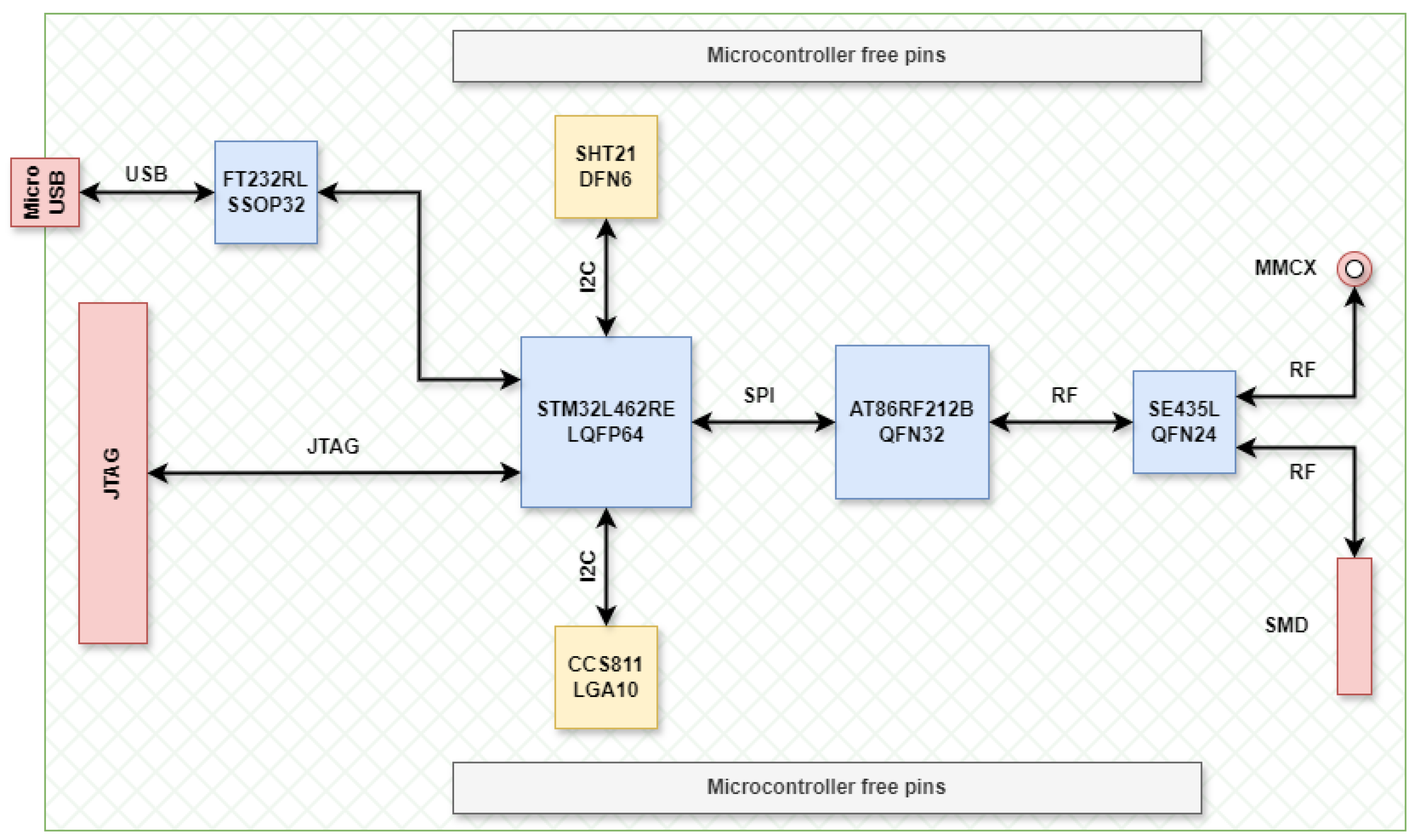
Figure 2.
Microcontroller wiring schematic.
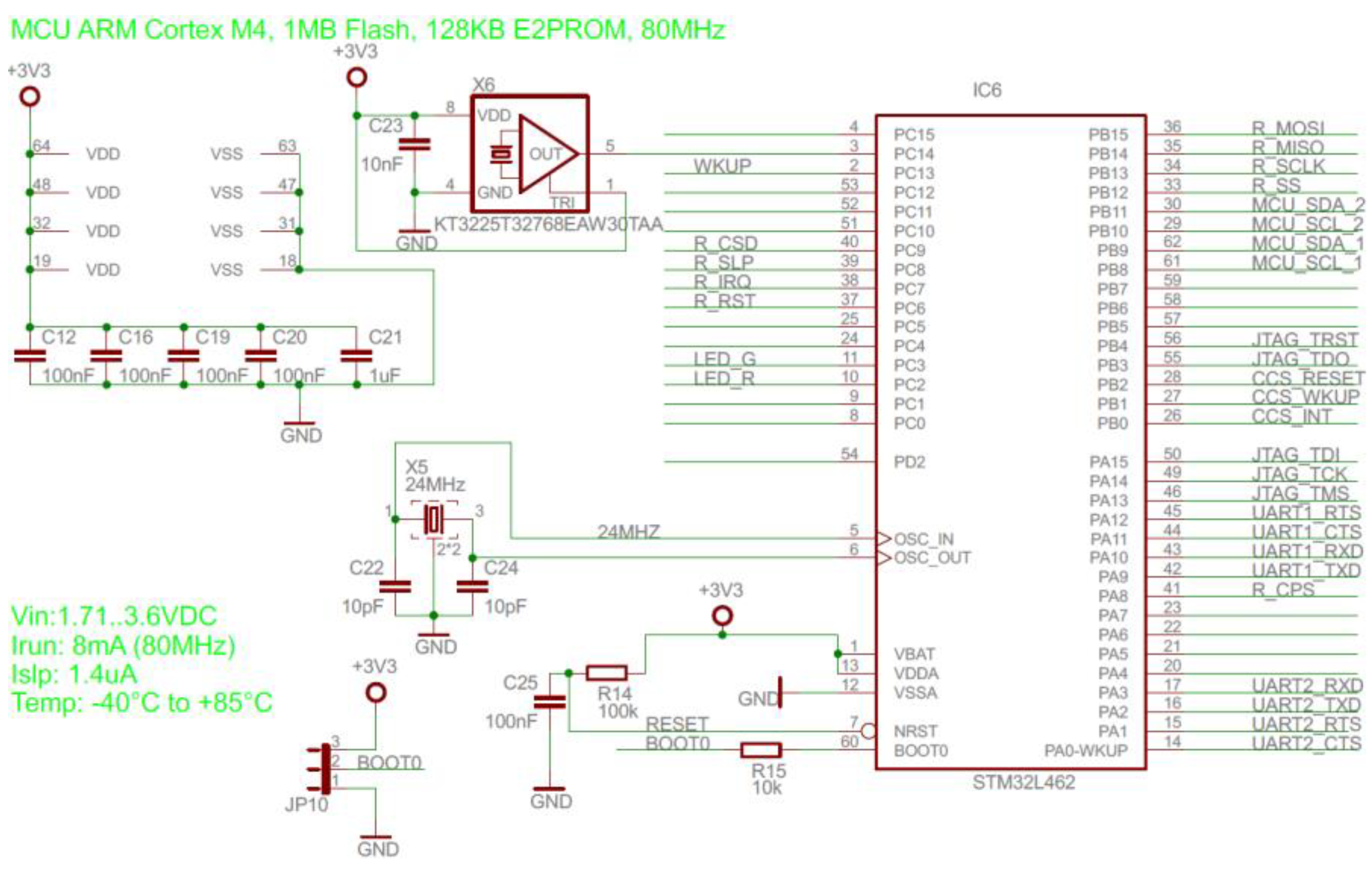
Figure 3.
Transceiver wiring schematic.
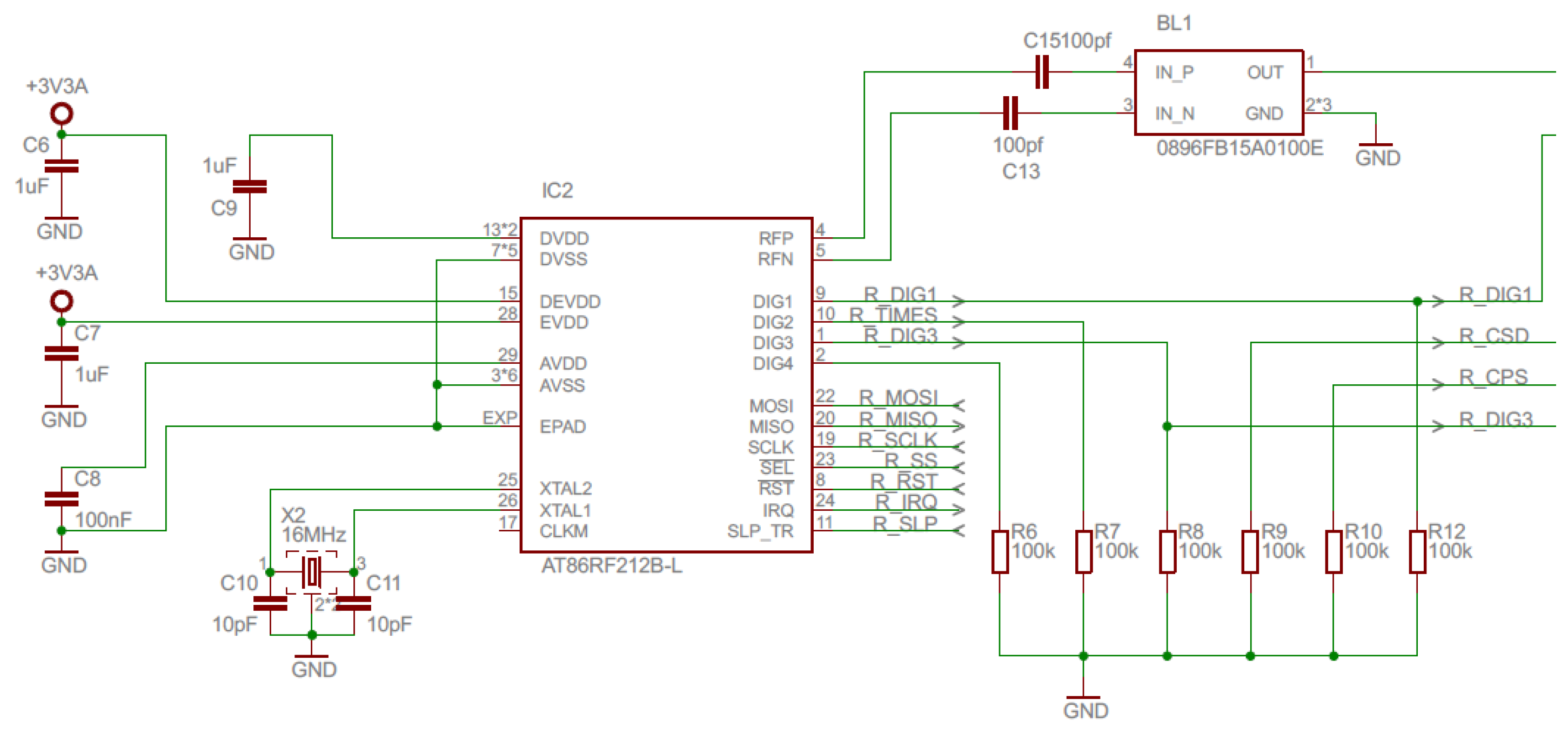
Figure 7.
Power amplifier current consumption.
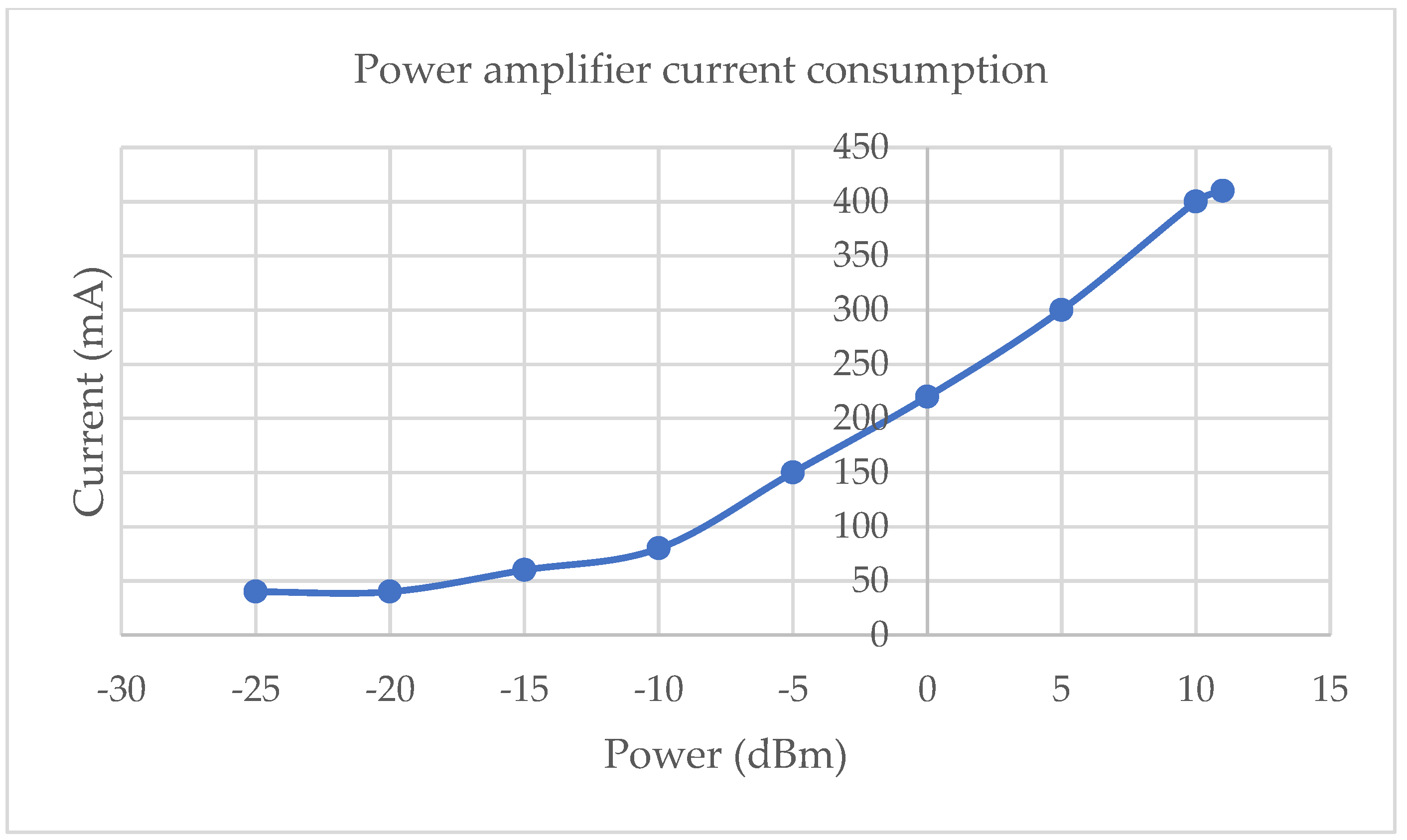
Figure 8.
Transmission testing.
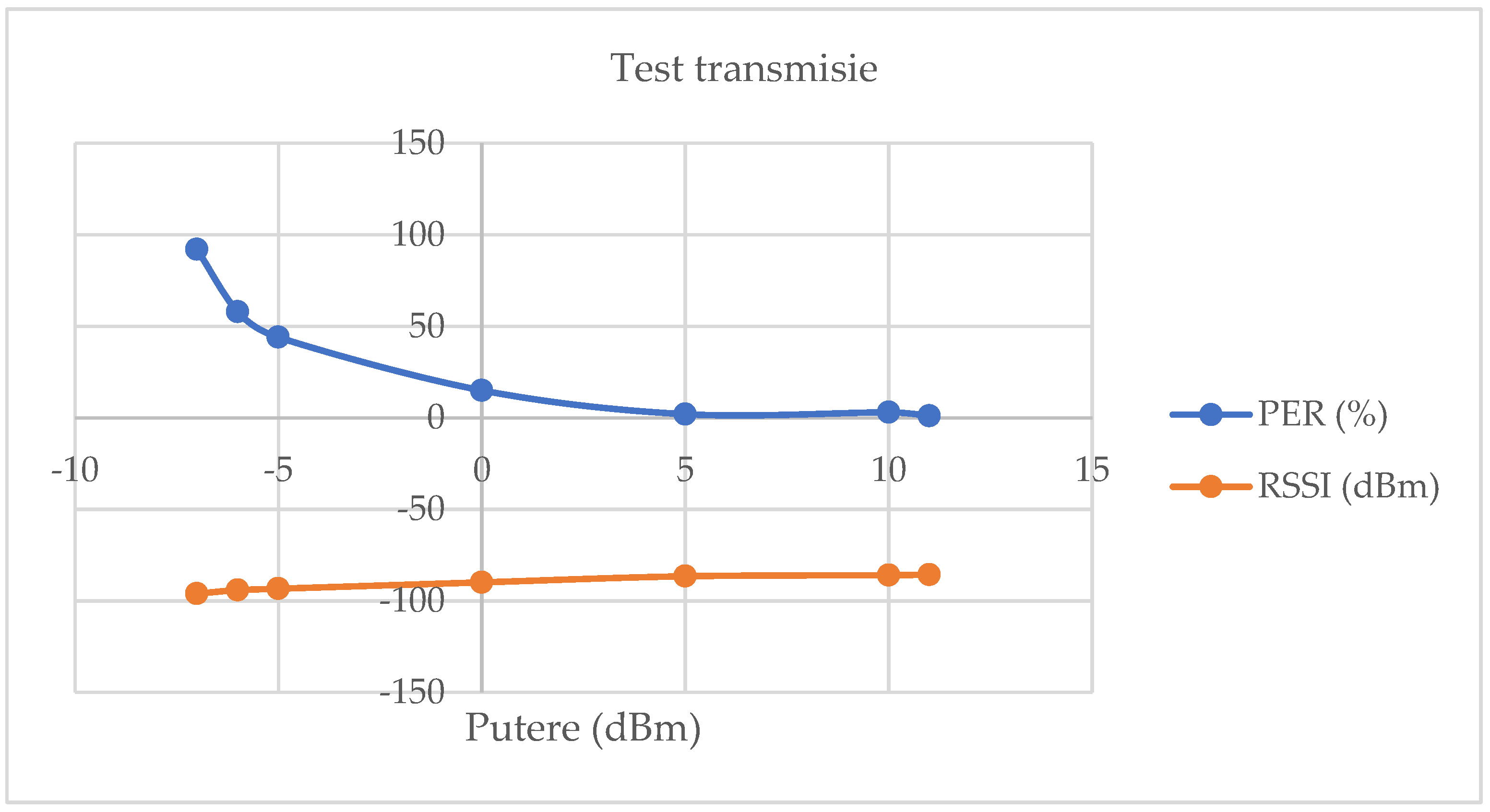
Figure 9.
Wireless control network topology.
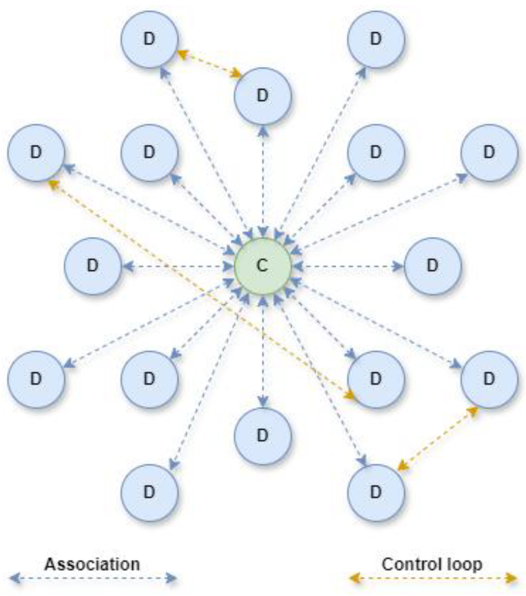
Figure 10.
Hardware setup used in the development of the wireless control network.
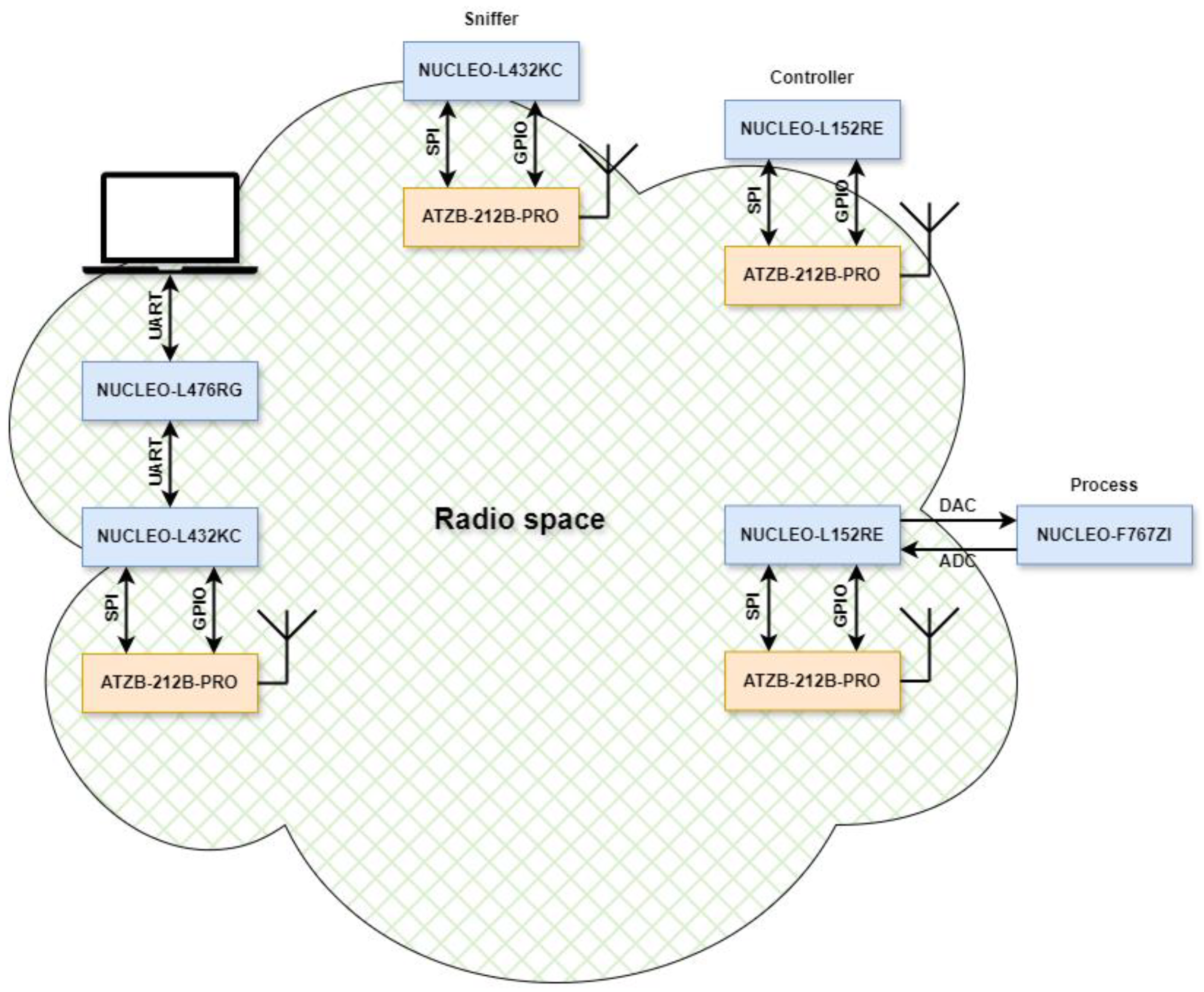
Figure 11.
TSCH CCA channel access operating mode.
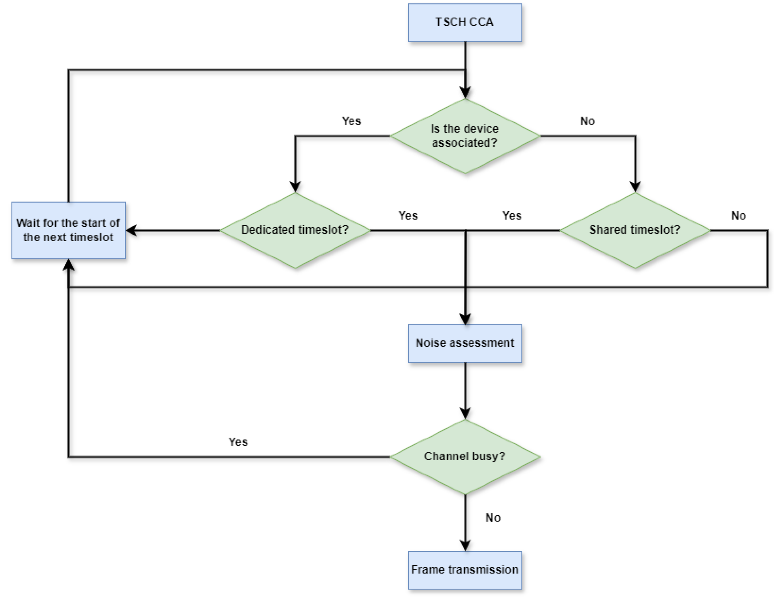
Figure 13.
Superframe structure.
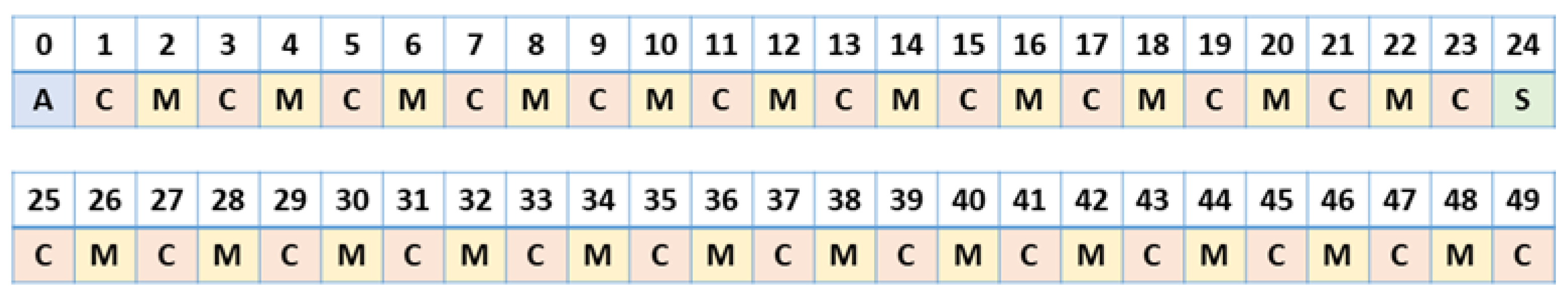
Figure 14.
Timing template.
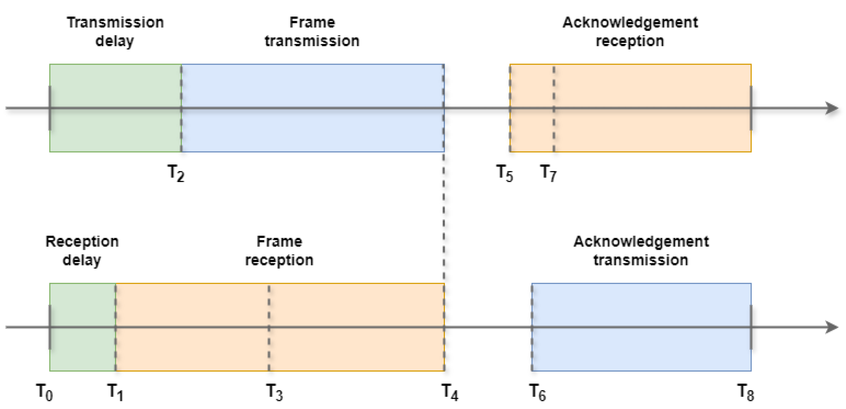
Figure 14.
Time synchronization.
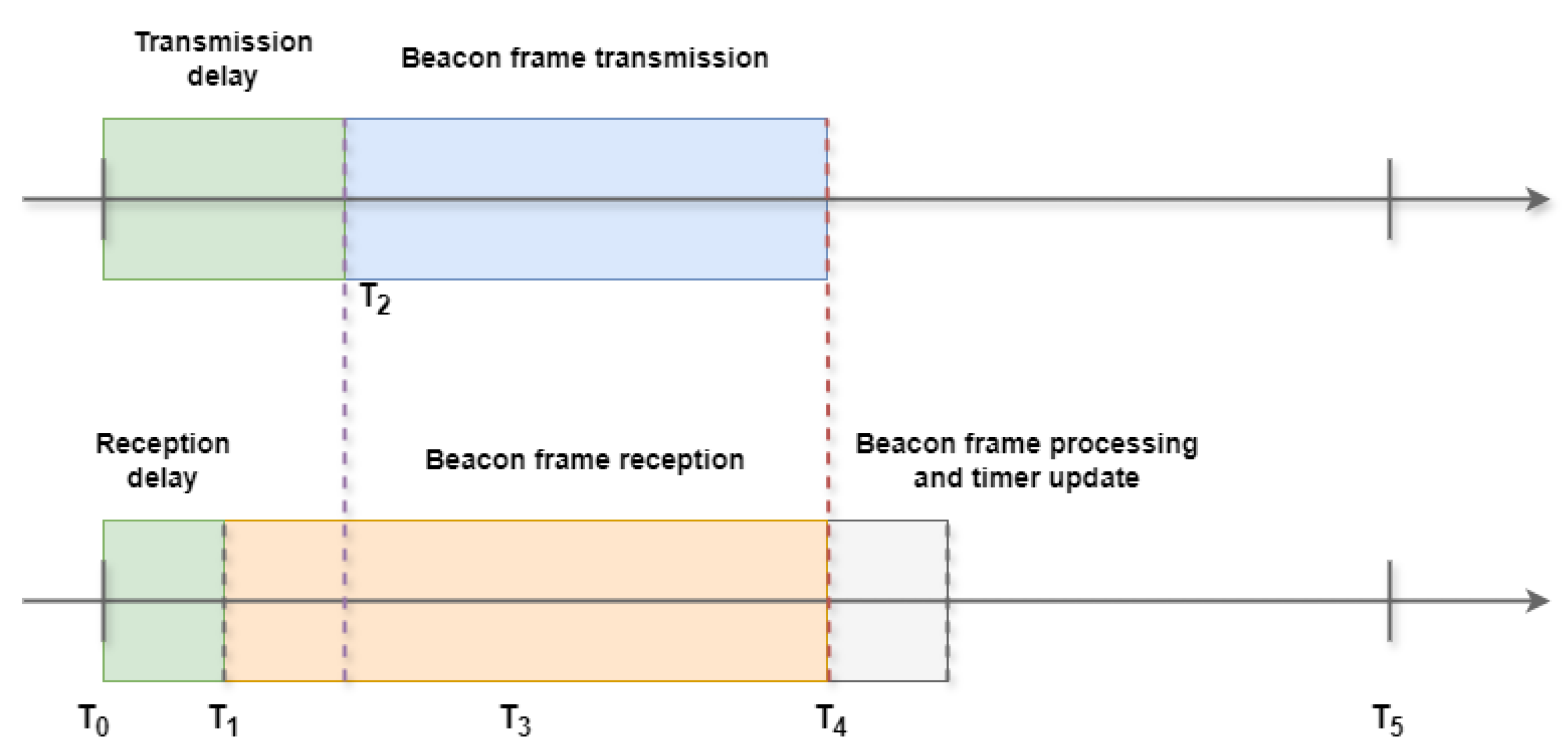
Figure 15.
Starting the wireless control network.
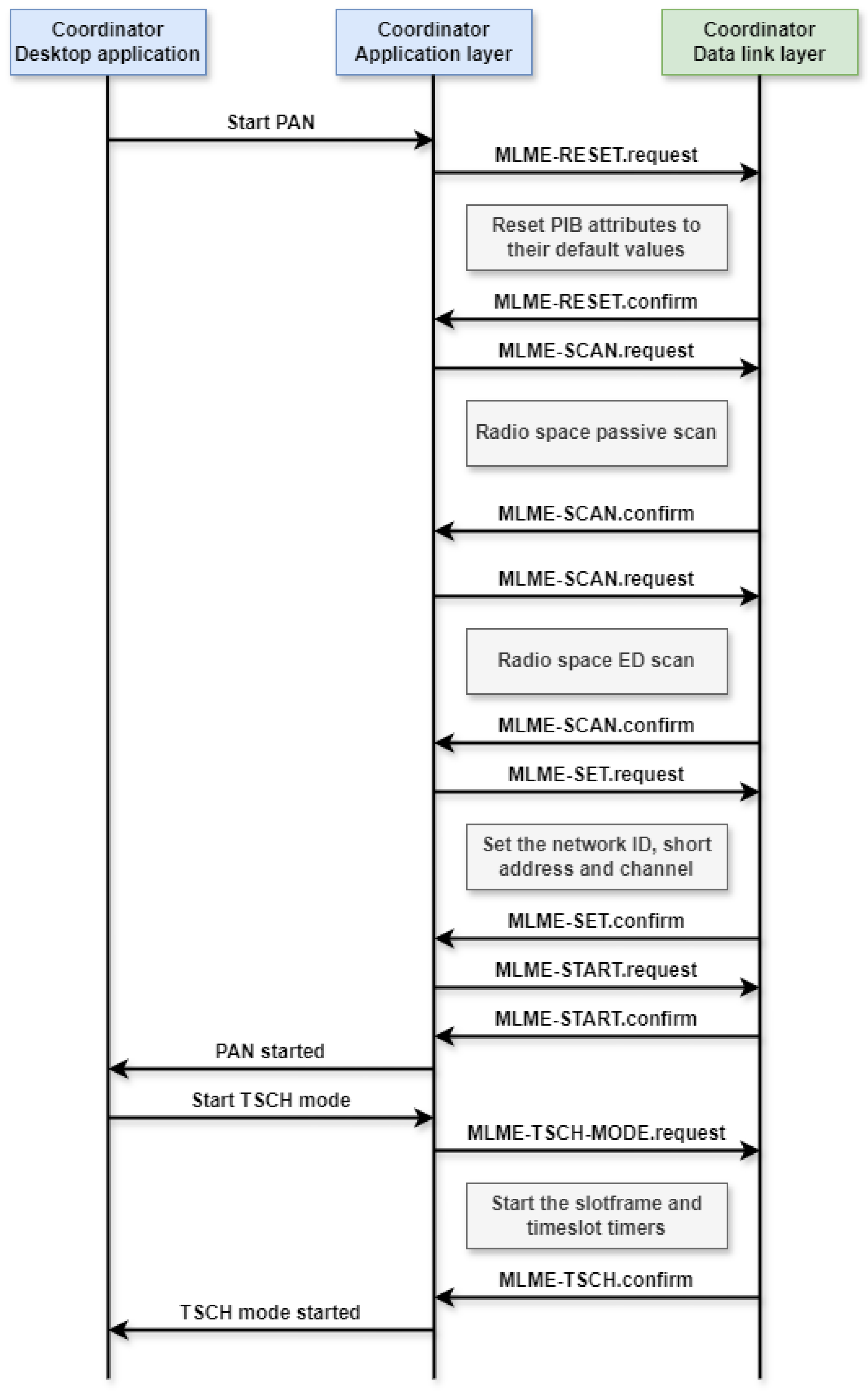
Figure 16.
Starting the wireless control network.
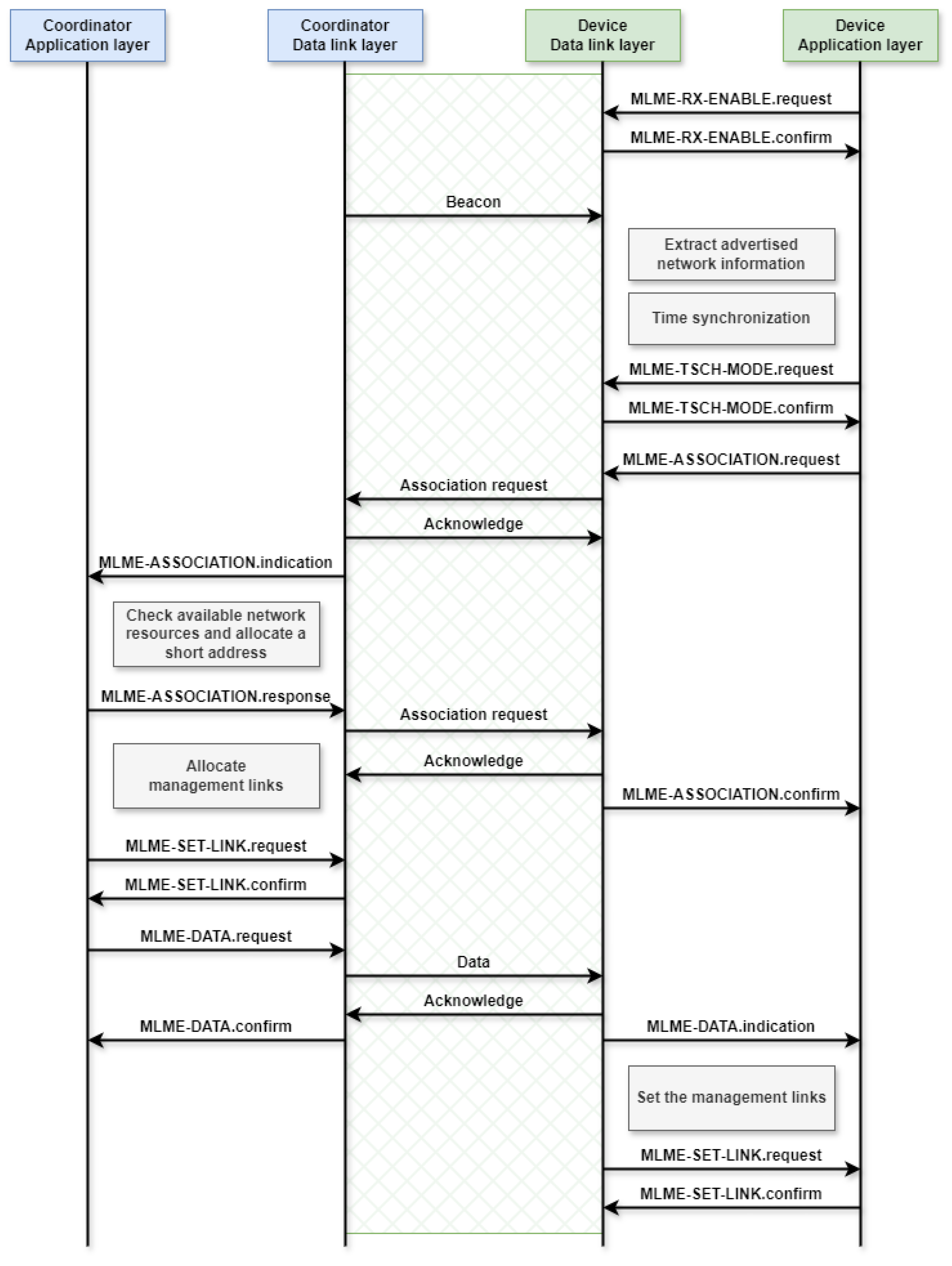
Figure 17.
The process controlled through the wireless control network: a car alternator coupled to an electric motor. (a) Diagram of the process. (b) The process in real-life.
Figure 17.
The process controlled through the wireless control network: a car alternator coupled to an electric motor. (a) Diagram of the process. (b) The process in real-life.
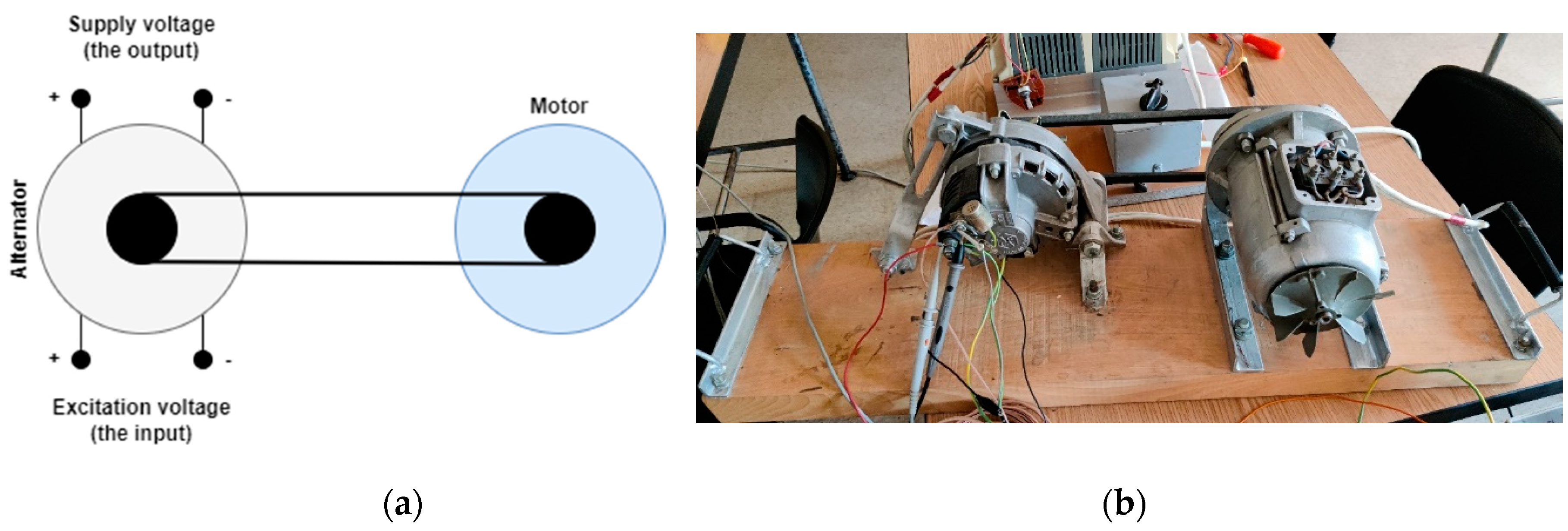
Figure 18.
Process identification.
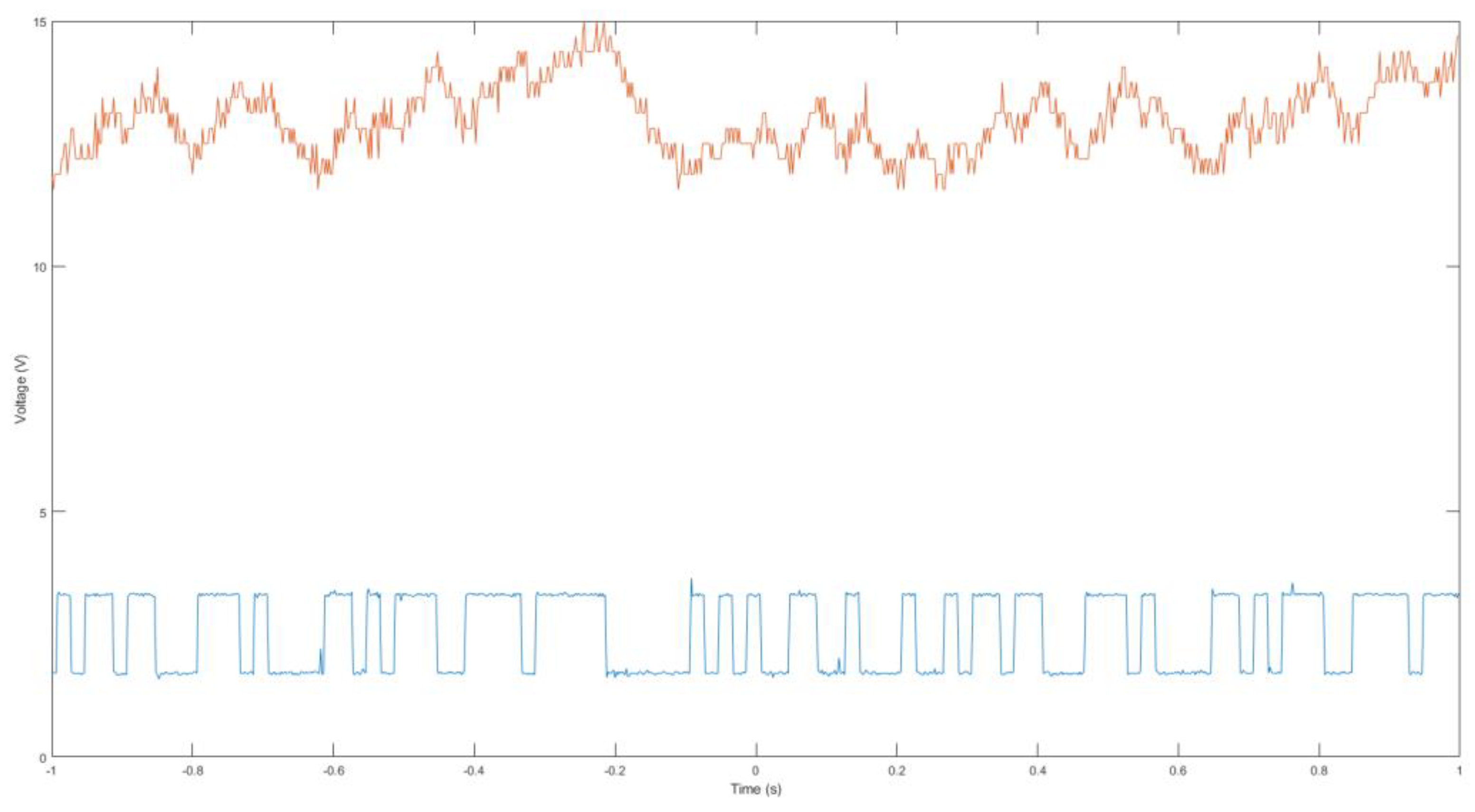
Figure 19.
The step response of the identified process.
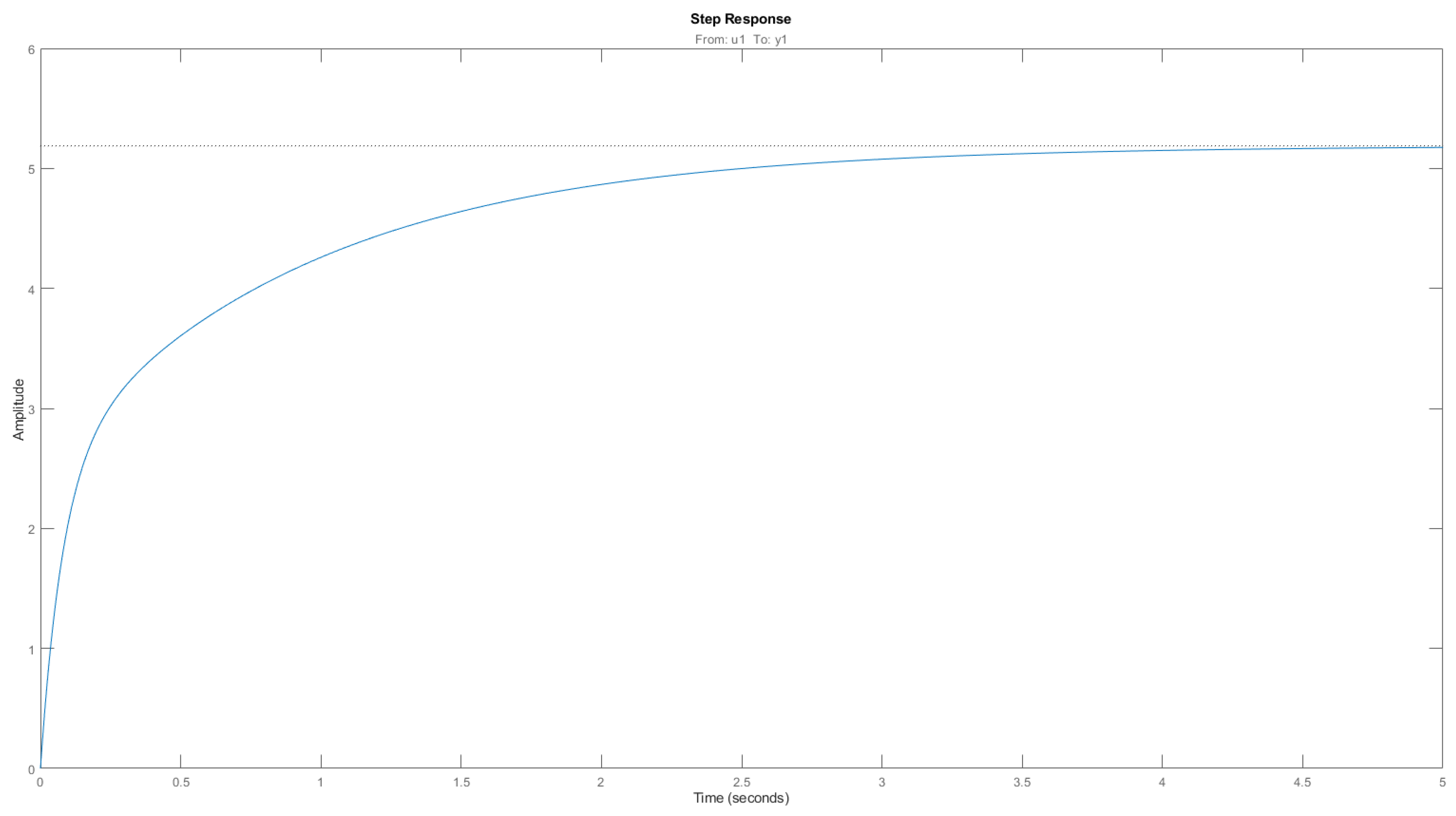
Figure 20.
The closed loop system responses as simulated in MATLAB. (a) The step response; (b) The controller output.
Figure 20.
The closed loop system responses as simulated in MATLAB. (a) The step response; (b) The controller output.
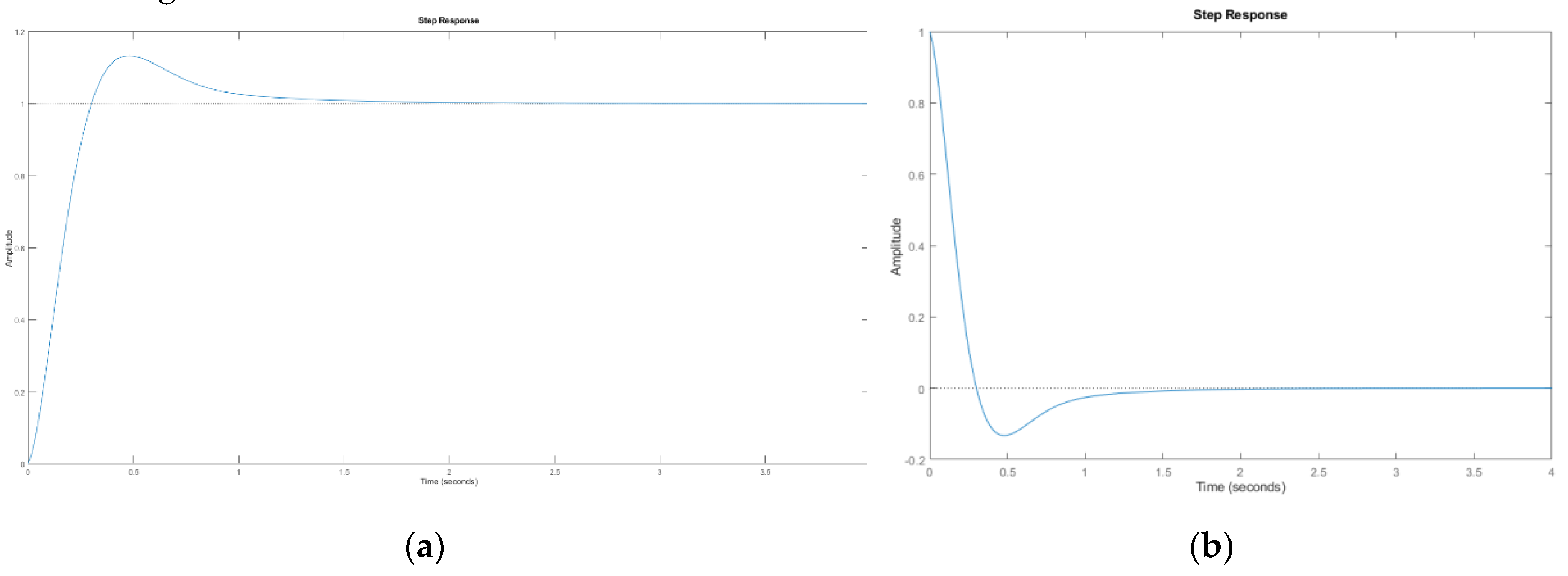
Figure 21.
Desktop application used for managing the wireless control network and the control loops.
Figure 21.
Desktop application used for managing the wireless control network and the control loops.
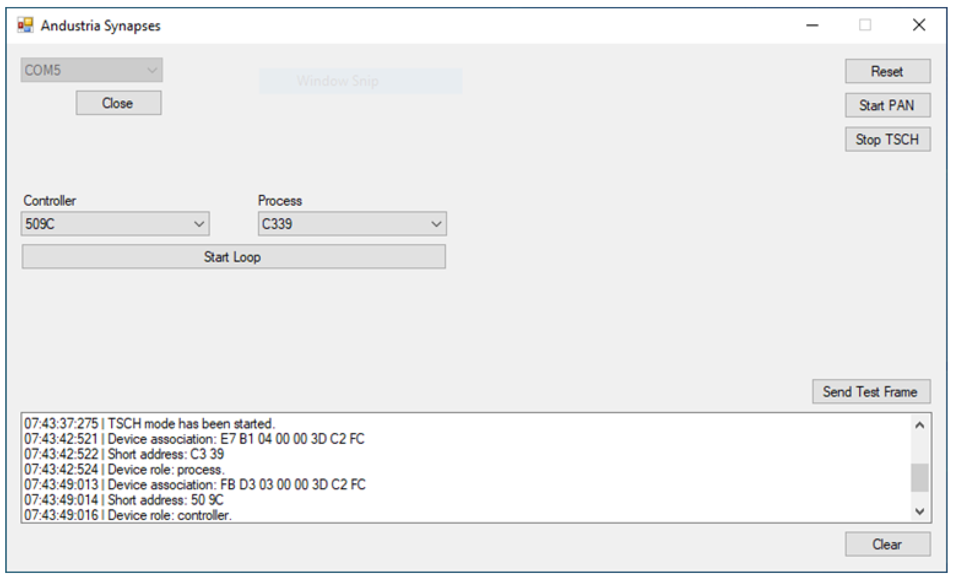
Figure 22.
Procedure for starting a control loop.
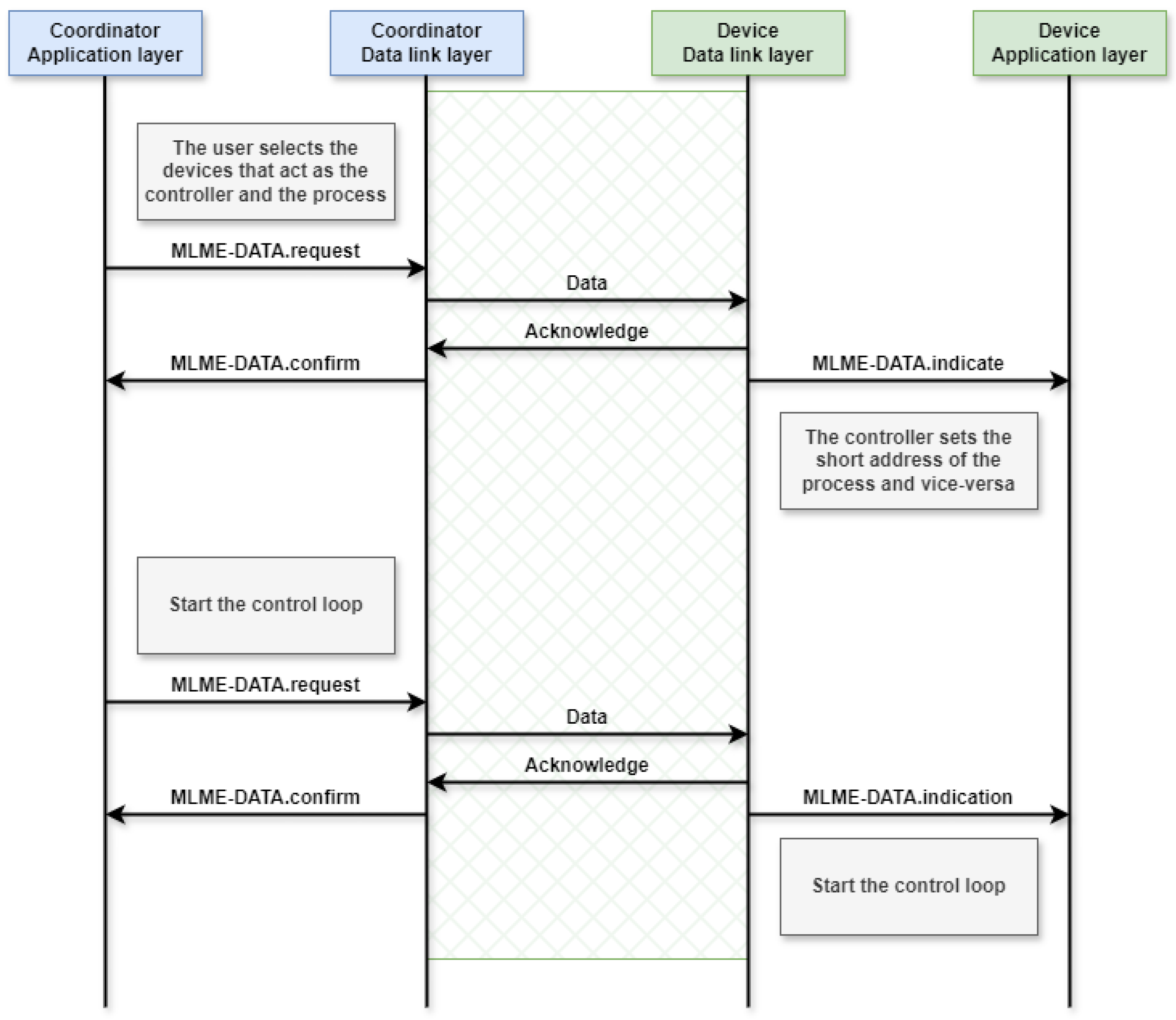
Figure 23.
Layout for simulated control loop validation.
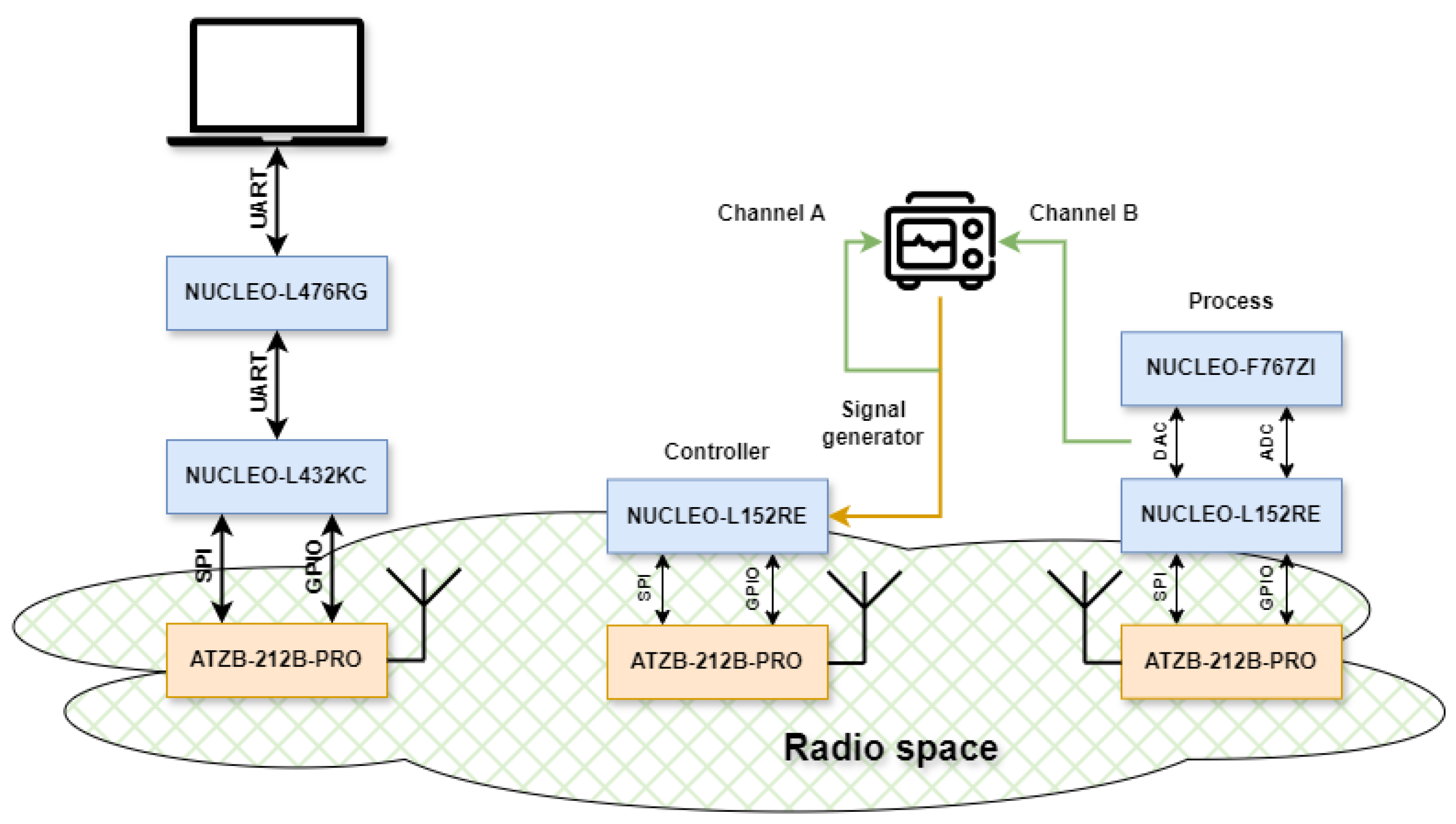
Figure 24.
The setpoint and the process output.
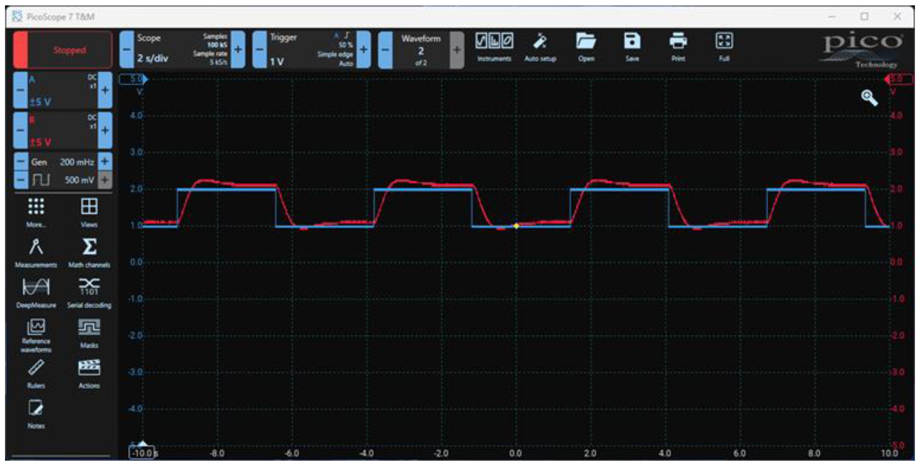
Figure 25.
The command applied to the process and the setpoint.
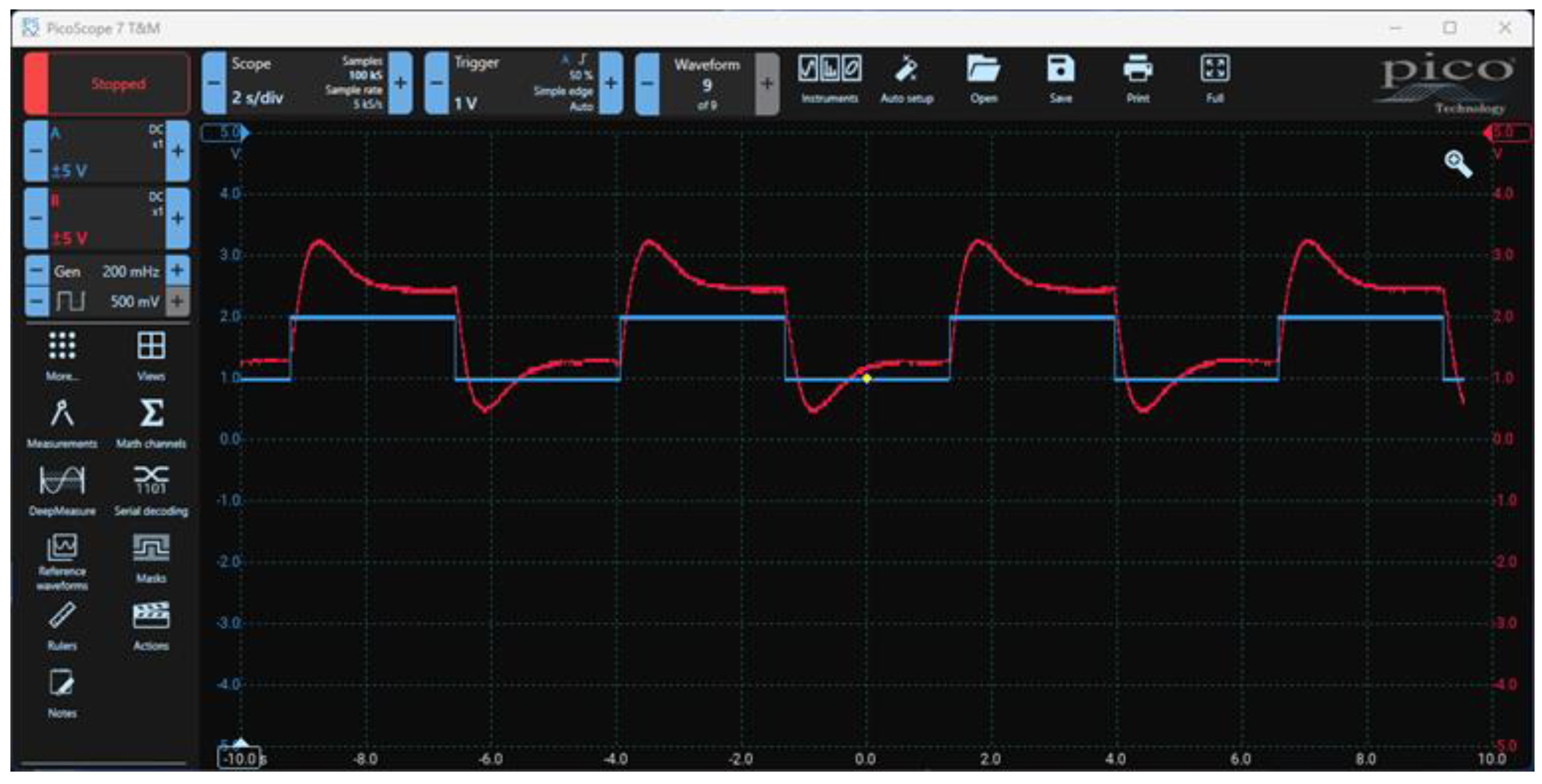
Figure 26.
Layout for physical control loop validation.
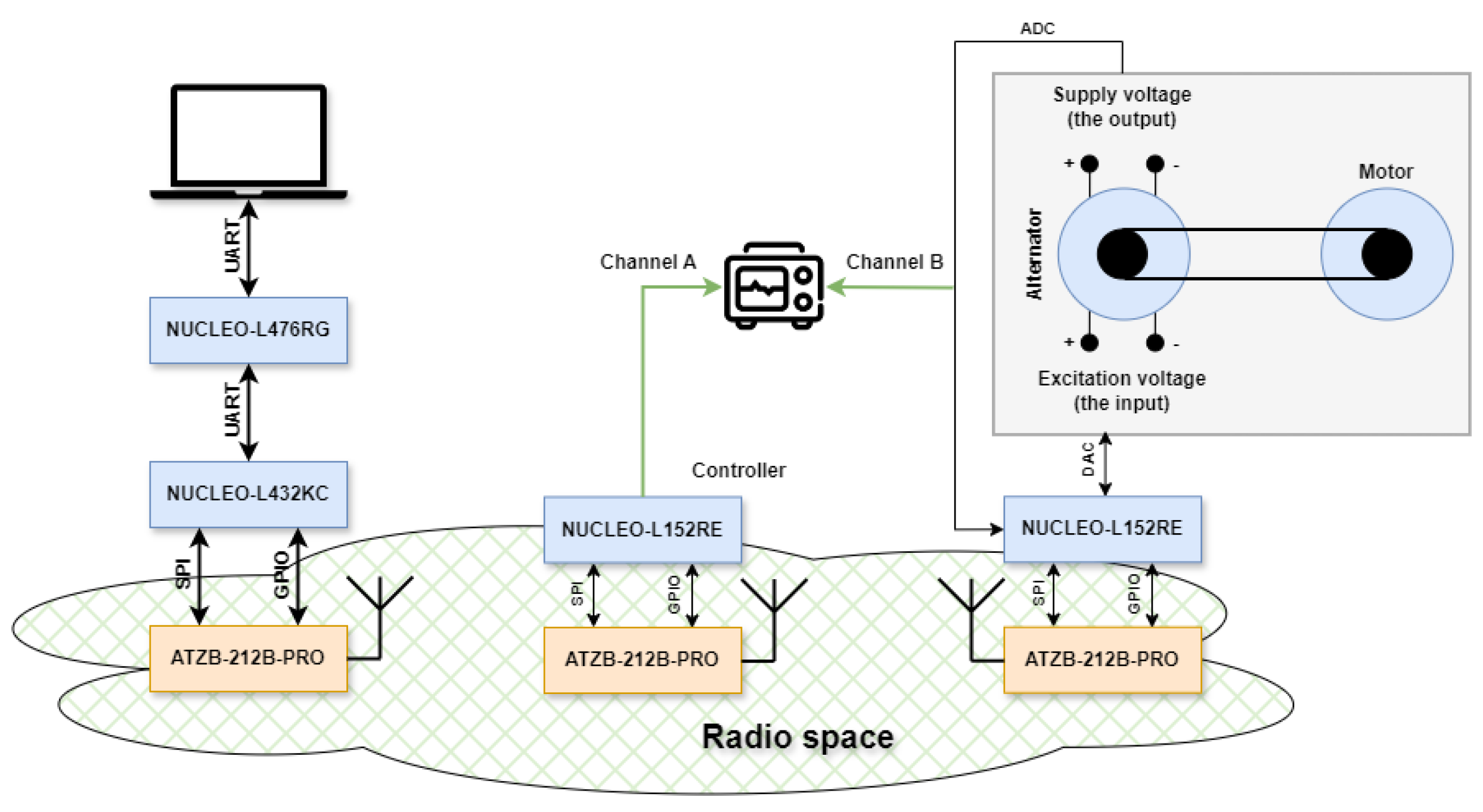
Figure 27.
Control loop validation setup.
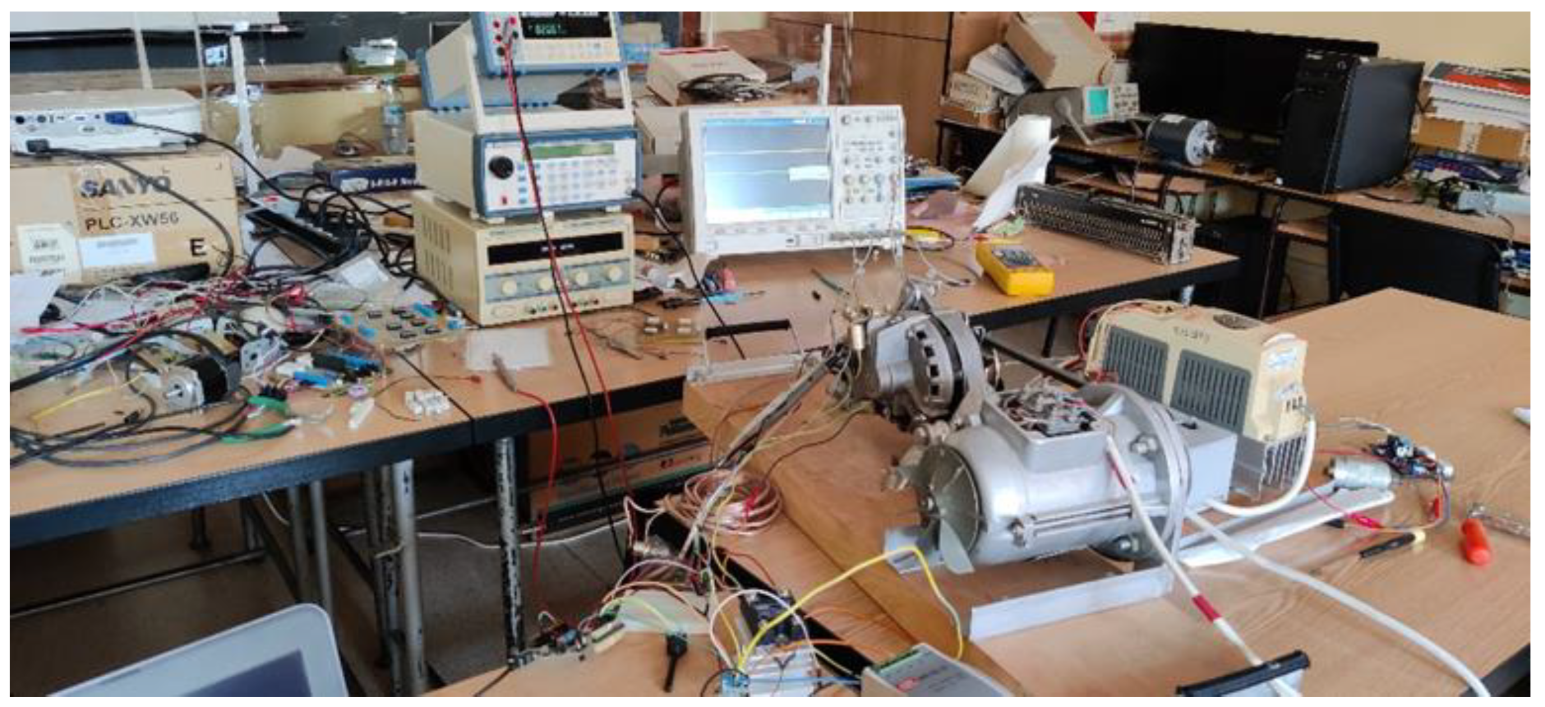
Table 1.
Feature comparison between wireless standards.
| Feature | ISA100 Wireless | Zigbee | LoRaWAN |
| Operating frequency | 2.4 GHz | 2.4 GHz | 868 MHz |
| Transfer speed | 250 kbps | 250 kbps | 0.3 ÷ 50 kbps |
| Network topology | Mesh | Mesh | Mesh |
| Maximum network size | 100 knots | 65,000 knots | 62,500 knots |
| Modulation | IEEE 802.15.4 2.4 GHz O-QPSK |
IEEE 802.15.4 2.4 GHz O-QPSK 868/915 MHz BPSK 868/915 MHz FSK |
433/868/915/920 MHz LoRa 868/915/920 LR-FHSS 433/868/915/920 FSK |
| Latency | 100 milliseconds | 15 milliseconds | 5 minutes |
Table 2.
Feature comparison between wireless standards.
| STMicroelectronics STM32L432KC | Texas Instruments MSP432P401R | |
| General characteristics | ||
| Core | Arm Cortex-M4F | Arm Cortex-M4F |
| Maximum operating frequency | 80 MHz | 48 MHz |
| FLASH memory | 256 KB | 256 KB |
| RAM | 64 KB | 64 KB |
| Supply voltage | 1.71 ÷ 3.6V | 1.62 ÷ 3.7V |
| Operating temperature | -40 ÷ 85 °C | -40 ÷ 85 °C |
| Consumption | ||
| Run mode | 84 µA/MHz | 80 µA/MHz |
| Sleep mode | 1.0 µA | 660 nA |
| CoreMark [19] | 3.42 CoreMark/MHz | 3.41 CoreMark/MHz |
| ULPMark [20] | 176.7 ULPMark-CP | 193.2 ULPMark-CP |
| Interfaces | ||
| ADC | 1 | 1 |
| DAC | 2 | - |
| UART | 3 | 4 |
| SPI | 2 | 8 |
| I2C | 2 | 4 |
| CAN | 1 | - |
| DMA | 14 channels | 8 channels |
| USB | Full speed | - |
| Package | UFQFPN32 | LQFP100 VQFN64 NFBGA80 |
| Price | €4.74 | N/A |
Table 4.
Transceiver current consumption.
| Mode | Consumption |
| Sleep | 0.2 µA |
| Idle | 450 µA |
| Reception | 9.2 mA |
| Transmission at +10 dBm | 26.5 mA |
| Transmission at +5 dBm | 18.0 mA |
| Transmission at +0 dBm | 13.5 mA |
| Transmission at -25 dBm | 9.5 mA |
Table 5.
Power amplifier current consumption.
| Mode | Consumption |
| Sleep | 1 µA |
| Bypass | 280 µA |
| Reception | 6 mA |
| Transmission | 410 mA |
Table 6.
Types of primitives defined by IEEE 802.15.4-2020 and the ones implemented for the wireless control network.
Table 6.
Types of primitives defined by IEEE 802.15.4-2020 and the ones implemented for the wireless control network.
| Primitive ID | Primitive |
| 0 | MLME_ASSOCIATE |
| 1 | MLME_BEACON_NOTIFY |
| 2 | MLME_BEACON |
| 3 | MLME_BEACON_REQUEST |
| 4 | MLME_CALIBRATE |
| 5 | MLME_COMM_STATUS |
| 6 | MLME_DBS |
| 7 | MLME_DA |
| 8 | MLME_DISASSOCIATE |
| 9 | MLME_DPS |
| 10 | MLME_GET |
| 11 | MLME_GTS |
| 12 | MLME_IE_NOTIFY |
| 13 | MLME_ORPHAN |
| 14 | MLME_PHY_DETECT |
| 15 | MLME_PHY_OP_SWITCH |
| 16 | MLME_POLL |
| 17 | MLME_RESET |
| 18 | MLME_RIT_REQ |
| 19 | MLME_RIT_RES |
| 20 | MLME_RX_ENABLE |
| 21 | MLME_SCAN |
| 22 | MLME_SET |
| 23 | MLME_START |
| 24 | MLME_SYNC |
| 25 | MLME_SYNC_LOSS |
| 26 | MLME_SOUNDING |
| 27 | MLME_SRM_REPORT |
| 28 | MLME_SRM_INFORMATION |
| 29 | MLME_SRM_REQ |
| 30 | MLME_SRM_RES |
| 31 | MLME_SET_SLOTFRAME |
| 32 | MLME_SET_LINK |
| 33 | MLME_TSCH_MODE |
| 34 | MLME_KEEP_ALIVE |
| 35 | MLME_DSME_GTS |
| 36 | MLME_DSME_LINK_REPORT |
| 37 | MCPS_DATA |
| 38 | MCPS_PURGE |
| 39 | MLME_LINK_TABLE |
Disclaimer/Publisher’s Note: The statements, opinions and data contained in all publications are solely those of the individual author(s) and contributor(s) and not of MDPI and/or the editor(s). MDPI and/or the editor(s) disclaim responsibility for any injury to people or property resulting from any ideas, methods, instructions or products referred to in the content. |
© 2025 by the authors. Licensee MDPI, Basel, Switzerland. This article is an open access article distributed under the terms and conditions of the Creative Commons Attribution (CC BY) license (http://creativecommons.org/licenses/by/4.0/).
Copyright: This open access article is published under a Creative Commons CC BY 4.0 license, which permit the free download, distribution, and reuse, provided that the author and preprint are cited in any reuse.


