
Submitted:
04 February 2025
Posted:
04 February 2025
You are already at the latest version
Abstract
Expected life and reliability of components is a critical aspect for railway applications where the expected life and maintenance intervals of rolling stock are quite demanding issues both in terms of equivalent mileage and duration. For these reasons when mileage of the mission is within 100 kilometers adopted accumulators are based on lithium titanate chemistry which, despite a relatively low density assure a very long operational life both in terms of cycle and time aging. In this work authors introduce a benchmark test case, an Italian line between Reggio Calabria and Catanzaro, in which the required autonomy, more than 170km, involves the usage of high energy batteries such LiNMC or LiFePO4 derived from corresponding automotive applications. In this work authors propose a simulation model based on IEC 62864-1:2016 to investigate how the combined effect of cycle and time aging should influence in different ways the design of the system and how relatively small interventions like the partial electrification of small intermediate section of the line should improve the overall stability and reliability of the performed engineering analysis.
Keywords:
Battery Operated Rolling Stock
; Simulation of multimodal trains
; IEC 62864-1:2016
; Design Sensitivity to Cycle and Time Aging
; Partially electrified Lines
; Mechatronics
; Direct and Inverse Dynamic Modelling of Longitudinal Train Dynamics
List of Adopted Symbols (in order of appearance)
Power requested or regenerated by Traction Equipment
Power dissipated by the braking Chopper
Power consumed by on board auxiliaries
Power exchanged with the Primary Power Source
Power exchanged with the on board storage system
Longitudinal effort applied to the Train Composition
Longitudinal displacement and its derivatives (speed,acceleration and jerk)
Train mass
gravitational acceleration
line slope and equivalent slopes introduced by lumped resistances such as curves and switches
coefficients of distributed motion resistances
Longitudinal Component of Wind Speed
Long. Effort conf. Parameter
Ratio between equivalent translational inertia and train mass
equivalent max deceleration associated to the max adhesion limits prescribed by TSI (Technical Specification for Interoperability)
equivalent max deceleration associated to total braking performances
equivalent max deceleration related only to electrical braking
Voltage level of collected current at the pantograph and corresponding threshold and maximum values
Voltage and Current of the Battery pack
Open circuit voltage of a cell, modelled as a function of SOC (State Of Charge)
number of cells connected in series and parallel in the battery pack
efficiency of battery static converter stage
Maximum recharge reference limit for battery recharge controller
Prop. Gain of the battery recharge controller
1. Introduction
The electrification of railway lines offers the possibility of removing most of the local direct CO2 emissions of rolling stock, however involved maintenance and construction costs are often justified only by relatively high traffic flows[1]. Data concerning the diffusion of electrified lines and more generally to adopted electrification standards are currently accessible from various national and international data repository. For the purpose of this work, most of the data have been taken from a free public repository “OpenRailwayMap”[2] which is substantially a detailed on line map of the world’s railway infrastructure, built with OpenStreet Map data, some of this data can be easily further, accessed and processed using large language models[3]. As shown in Figure 1, the diffusion of electrified lines is still affected by complex geo-political issues related not only to cost of energy, climate and internal demography of countries but also by historical and political choices: as example, extensively electrified networks should be found in highly industrialized countries like the ones of the BENELUX area, but also in emerging powers like India or even in countries that suffer of persistent industrial and political isolation like North Korea. At the same time the persistency of not electrified lines in many highly developed countries is often a matter of opportunity in terms, as example of economical sustainability. Climate and sustainable development goals should boost the diffusion of electrified lines, involving large investments that should be only partially justified in terms of terms of economic return. In this sense the adoption of Battery Operated [4,5] or of Hybrid trains[6,7] represent an interesting perspective to reduce direct emissions with reduced investments and infrastructural impacts on the territory. Also, recent studies [8] in which the overall sustainability of different solution is compared, clearly indicates that in many different operational scenarios both battery-operated, and hybrid trains should be more sustainable also considering the environmental impact of the infrastructure. An impact that in sensitive natural or historical sites should be also considered as unacceptable. For all these reasons there is a growing interest for the development of studies in which the optimization of battery-operated and fuel cell systems is performed for a specific train over a specific mission profile as in the recent work of Fragiacomo et al. [9].Also this analysis can be completed also considering some preliminary evaluations of the aging of the components as done as example by Spedicato [10]. The same problem, the compensation of aging effects of critical components like fuel cell is also the object of recent works in which this issue is managed with an extensive use of artificial intelligence as proposed by Deng et all.[11] or by other authors for what concern batteries [12,13].
Other recent works such as the one of Vignati [14] concern the integration of hybrid and battery-operated powertrains for what concern unmanned driverless systems used for diagnostic purposes also under electrified lines.
In this work, authors focus their attention on the simulation of battery operating rolling stock with a particular attention to a new emerging category of BEMUs (Battery Electric Multiple Units) designed to reach maximum autonomies between 200 and 300 kilometres to cover the exercise over partially or not electrified lines in which the required autonomies without external recharge are over 150 kilometres. This focus on local passenger traffic is justified by the specific features of the railway market in Italy and more generally in western Europe that privilege the application of battery-operated rolling stock to local passenger transportation, but similar technologies can be applied also to freight trains [15].
To reach this objective the size of installed batteries should significantly grow with respect of conventional autonomies of 50-100 kilometres: in this kind of applications reliability and durability specifications that are typical of the railway sectors are obtained by installing LTO (Lithium Titanate) battery packs which assure a cycle life over 10000 cycles and probably the highest stability in terms of time aging[16]. Chemistries currently used for automotive applications like LiNMC and LiFePO4 offer much higher energy densities being much cheaper with respect of their LTO counterparts [17,18]. However, their expected life in terms of equivalent charge and discharge cycles is often limited (2000-4000cycles) and sensitivity to calendar aging is typically higher [19]. Also, thermal stability and more generally reliability vs. off design condition is a bit more critical for LiNMC batteries with respect of LTO ones. So, in this work authors focused their attention on the preliminary simulation of a benchmark BEMU on an Italian Line from Reggio Calabria to Catanzaro Lido for which an extended autonomy of at least 150 kilometres is required. This line is a well-known benchmark offering the possibility of a comparison with other studies related, as example, to the application of hydrogen powered rolling stock[9]. For what concern the proposed benchmark train, authors considered a BEMU inspired to the existing Blues-Masaccio Platform for which a large amount of free information are freely available online[20-22]. Also, in this case proposed rolling stock offers the possibility of further comparisons with previous studies [23] regarding the application of fuel cell technology which is probably one of the most important concurrent technologies for what concern both autonomy and sustainability.
Different kind of storage system can be installed on railway rolling stock for the purpose of this work attention is focused on electrochemical batteries. Attention is focused on lithium chemistries that should be considered the best candidates for this kind of applications LTO (Lithium Titanate) and LiNMC (Lithium Nickel, Manganese, Cobalt).
The two chemistries are almost equivalent in terms of total stored energy during the expected battery life. The specific energy of a cell Espec represents the quantity of energy that can be stored per unit of mass. Neglecting calendar aging life can be expressed in terms of equivalent number of charge and discharge cycles. The total quantity of energy that can be stored per mass unit during the entire life of the cell is represented by Espec_Ncycles (1).
The corresponding comparison of the two chemistries in terms of Espec_Ncycles is shown in Table 2, demonstrating their substantial equivalence.

Table 1.
Expected Total Stored Energy during the life of batteries with different chemistries.
| Chemistry | Specific Energy | Number of Cycles | Total Stored Energy |
| LiNMC | 200 [Wh/kg] | 2500-4000 | 500000-800000[Wh/kg] |
| LTO | 50 [Wh/kg] | 10000-16000 | 500000-800000[Wh(/kg] |
So, the idea that guide this research is to use LiNMC batteries to obtain a storage which has the same weight of a conventional LTO storage, the same life in terms of mileage/service duration. Beyond this equivalence the autonomy assured by a LiNMC batteries with a single battery recharge is much higher since the capacity of the storage is much higher.
So, it can be concluded that the adoption of LiNMC storages should offer the possibility of performing longer missions with respect of LTO ones, without penalizing too much the life of the battery. The validity of this approach must be verified with simulation tools able to also verify the effect of calendar aging which is substantially negligible for LTO batteries but not for LiNMC ones.
Analysis is performed with the following steps:
- Train model and adopted simulation platform is introduced.
- Then battery is sized with respect of available load capabilities of the benchmark rolling stock.
- Then a simulation campaign is performed to evaluate the combined effect of cycle and calendar aging of kind and sizes of battery pack.
- Finally Obtained results are critically evaluated concluding the work
2. Adopted Train Model
The behaviour of the simulated rolling stock is performed adopting a Matlab-Simulink model that reproduce the general powertrain scheme that is currently proposed by regulations in force, such as the Standard IEC 62864-1:2016[24] as shown in Figure 2, the model is divided is six sub models that can be combined in different ways to simulate different multimodal powertrains:
- Traction Equipment: calculation of consumed or regenerated power PTE according to mission profile.
- Brake Resistor: calculation of the power PBR that should be dissipated during a braking manoeuvre.
- Auxiliaries: calculation of consumptions of auxiliaries PAUX like HVAC or pneumatic brake compressors.
- Primary Power Source: in multi modal hybrid system, primary power source is the main source of power (PPPS) of the system, it should be a prime mover like a fuel cell or a diesel motor or the external connection (as example the pantograph) with an external source of electrical power. For the purpose of this work the primary source is the pantograph for service under electrified line or other devices for fast recharge in standstill conditions.
- Energy Storage ESS: in every multimodal system there is the need for a storage working as power/energy buffer. From a physical point of view this sub model corresponds to the model of an electrochemical (battery) or electro-static (capacitor) storage able to exchange the power PESS. For the purpose of this work, investigated batteries are the storage.
- Power Management Logic: this sixth block/model is not represented by the scheme usually adopted by regulation by IEC 62864-1:2016, but it is fundamental as much as the other ones since it represent the logic that regulate the power flow exchanges between the over described elements.
2. 1 Traction Equipment Block
To calculate the traction loads associated to mission profiles is fundamental to reproduce a realistic mission profile starting from an assigned timetable respecting constraints imposed by the infrastructure, by traction and braking performances.
Vehicle dynamics can be solved using both a direct dynamic approach or an inverse dynamic one. Referring to previous studies cited in this paper[4,7,9] most of the work found in literature adopt a direct approach in which the Davis model(2) is directly solved especially when the object of the investigation is to evaluate how engineering constraints such as battery state or interaction with other external constraints (as example power limitations on catenary) should affect the performed mission[25,26]:
Otherwise, if the attention is focused on the precise reproduction of a timetable, inverse dynamic approach is preferable. Currently the proposed model support both approaches (different Simulink subsystem/instances are called). In both case the generation of a reference mission trajectory with a strict timing is mandatory.
As shown in Figure 3/a, the mission profile is decomposed in intervals which represents in a simplified way the signaling blocks/sections [27] in which is divided the line. For each signaling section is defined a speed limit. Blocks are defined and delimited by a vector of location nodes xbound. A subset of these location are the protected ones. The final speed of the train at each protected location is imposed. For this work, it’s equal to zero.
As shown if figure 3/b, the trajectory of each section is decomposed in a sequence of five curves:
- A limited traction jerk trajectory: train is accelerating with maximum jerk imposed according to maximum traction slew rate of the simulated rolling stock.
- A limited acceleration trajectory: train is accelerating with a maximum acceleration that respect the limits imposed by the maximum acceleration that can be calculated according to (2) by solving the Davis model:
(3)
- A limited speed trajectory.
- A limited braking jerk trajectory: train is braking with a maximum jerk imposed by the limited application rate of braking forces as stated by various standards such, as example, fiche UIC 540 [28].
- Braking Deceleration Curve: This is the maximum deceleration that can be applied according to applied braking power and motion resistances that is also calculated according to (2).
The trajectory of each block/section is then iteratively optimized with a nested procedure: an internal loop iteratively optimizes the speed profile of each section/block minimizing the traveling time with respect of imposed kinematic constraints (jerk, speed, and acceleration limits) and continuity on boundaries. Then an external loop further fits the traveling time between protected locations by reshaping the speed limit constraints of signaling blocks between two protected locations. Different reshaping criteria can be applied[29] (corresponding to different optimizations), currently a scaling of speed limits is applied. As shown in figure 3/c the scaled speed profile maintains the traveled distance (integral of speed with respect of time is the same), but the new arrival time fits the desired timetable.
The total power PTE can be calculated as the sum of the contribution due to traction PTET(4) and electrical braking PTEB (5) which respectively take count of efficiencies ηTE (electrical eff. of converters and motors) ηm(efficiency of mechanical transmission) and to adopted brake blending policy (kblend coefficient):
The kblend coefficient is calculated as the ratio between the maximum electrical braking effort Teb and the total braking effort Tb whose behavior is typically described in terms of mass-scaled efforts o equivalent deceleration as shown in Figure 4.
Max equivalent deceleration permitted for allowed adhesion limits according to TSI regulations [30] is defined according to (6):
TSI limits described by(6) represent the maximum allowed braking performance in terms of employed wheel rail adhesion, so total braking efforts applied to the train must be a bit lower, the associated equivalent deceleration is described by(7)
With respect of the total braking performance described by (7) the maximum electrical contribution is limited by performances of motors and converters, the resulting equivalent deceleration is described by(8).
Also, in figure 4 the typical profile of Teb(ω) and consequently of equivalent acceleration is shown evidencing some typical features:
- No electric Braking Region: for low speed, (typically lower than 30km/h) electric braking cannot be performed so it is gradually removed with bump less transition.
- Constant torque Region: in this region maximum braking effort is almost constant.
- Iso Power region: when the nominal speed of the system is reached the torque decreases with speed describing an Iso Power Hyperbola.
- Iso-Slip region: if the motor is an induction machine, over a known speed, motor slip cannot be further increased so the effort decreases more rapidly with a progression that is approximately to the inverse squared value of speed.
2.2. Brake Resistors Block
When electrical Braking is applied (PTE<0) the power generated by traction equipment can be regenerated to the primary source (as example sent back to catenary through a pantograph); otherwise, it can be employed to recharge the on-board storage system or to feed auxiliary systems.
Brake Resistors are activated to dissipate the part of electric braking that cannot be allocated or regenerated to other loads. So calculation of power dissipated by brake resistors ca be calculated according to (9):
2.3. Auxiliaries
The term auxiliaries is used to describe loads associated to different services such as HVAC (Heating, Ventilation, and Air Conditioning), Pneumatic Braking and other pneumatic services; Statistical distribution of auxiliary loads is shown in Table 2.
Auxiliaries are an important source of consumption, since according to literature these loads represent at least the 20% of total energy consumptions for both urban [31] and conventional rail [32] transportation. Typically, auxiliary loads are treated as a mean constant load PAUX (as example a mean consumption of 30kW for each coach) which is applied even when the train is not moving. Also, in this work PAUX is considered constant load during a mission. For this reason, it’s very important to take count of the duration of stops in stations and of the all the time in which as example the rolling stock is prepared for a mission.
2.4. Primary Power Source
In series hybrid systems, PPS (Primary Power Sources) are devoted to supply electric energy to other onboard subsystems by either consuming the fuel stored onboard or taking energy from external sources. For the modelling of a BEMU, Primary power source is represented Pantograph-Catenary current collection that feed the vehicle under electrified lines also assuring the recharge of onboard batteries. Irreversibility and line impedance play a key role in limiting regenerative braking when the onboard storage is fully recharged since the regenerated power must be limited if line overvoltage occurs. To protect both line and rolling stock against overvoltage (corresponding to a max voltage Vmax) the regenerated power PPSS is proportionally scaled, if the voltage at the pantograph Vc, exceed a threshold value Vth . The scaling factor kreg is defined according to (10).
(10)
For what concern traction and recharge performances, further limitations arise from limited performance of conventional railway pantograph of collecting high current in standstill conditions as described by current standards [33]. For what concern the modelling of the rolling stock it implies a severe limitation of static recharge performance vs the dynamic one. A limitation that can be eventually compensated adopting the collection with multiple pantographs or with modified, dedicated devices.
2.4. Storage Block
For the purpose of this work, batteries are modelled as an equivalent system whose voltage Vbat is described by (11) as a function of the open circuit voltage of the cells Voc and of the drop due to an internal cell resistance Rcell. Both Voc and Rcell are scaled according to the number of series (ns) and parallel (np) connected cells that are used for the battery assembly. Battery State of Charge (SOC) is calculated according to its definition as the integral of battery currents with respect of battery capacity. For what concern the sign of current I, a positive sign corresponds to battery recharge.
For what concern detailed modelling of both calendar and cycle aging, for standard simulations this calculation is omitted. For this work, specific approach for battery aging is fully described in the following section 3 related to performed simulations.
If the storage block is connected to the DC bus through a static converter efficiency is modeled introducing a conversion efficiency ηDCDCbatt .
2.5 Energy Management Logic
Power management is a subsystem that is not specifically described by regulations in force [24] but it plays a mandatory role since it describe the way in which power is managed between the five subsystems described in the scheme of figure 2.
For this work energy management logic is described by a relatively simple set of equations according to the performed maneuver and of the state of internal components and subsystems such as batteries or availability of the primary source (the electrified line).
The input of the logic is represented by the power demand of the train PTR which is defined by the sum of the power demand of both traction equipment and auxiliaries.
According the sign of PTR is possible to define the quadrant of operation of the system: if PTR is positive the train is absorbing power from primary source and storage otherwise is generating energy that must be dissipated or regenerated.
In the first case (PTR is positive) two further subcases are possible:
- The line is electrified: PTR is directly collected from the overhead line respecting the power balance (13). Where the recharge power of the battery PESS is calculated according to relation (14) and eventually saturated/limited with respect of current limits imposed by both battery BMS and by overhead line (including interposed power converters). Control (14) introduces a proportional recharge with respect of the difference between desired maximum SOC (SOClim) and the current one.
- The line is not electrified: all the power is provided by batteries(15). So if PESS is not enough or the battery is depleted, system performance must be degraded.
Other otherwise if the train has the possibility of regenerating power (PTR<0) , this power can be transferred to batteries, to overhead line (if available) and then to braking chopper(16).
Load transfer to these three alternative sinks is performed considering the following priority levels:
- PESS: battery is the first choice; the battery is recharged according to maximum allowed power limits until the max SOClim is reached.
- PPPS: all the power exceeding the maximum performance of the battery should be regenerated to the overhead line if the train is traveling along an electrified line. If the overhead line is not able to manage the regenerated power, PPPS is automatically limited according to (10).
- PBR : all the generated energy that cannot be regenerated to batteries or to overhead line is dissipated by the braking chopper. Also, the braking chopper should have limited performances. If even the performances of the braking chopper are exceeded, electric braking will be reduced in favor of conventional pneumatic braking.
3. Battery Sizing and Simulation
3.1. Battery Sizing: verifications of available weights and encumbrances
To properly size the battery system, a preliminary evaluation of volumes and weight available on existing hybrid DMU and HMU, must be performed. Main features that are considered for the benchmark train are shown in Table 3.
Available load capability and volumes that can be exploited to convert the benchmark train into a BEMU are calculated considering the removal of some components like the ICE powerpack or the power-buffer batteries.
In order to avoid the usage of potentially reserved or sensitive data, like original CAD files, authors extrapolate available volumes from the material that was freely available on line [20-22].
As shown in Figure 5, most of the available volume is located on the roof of trailer coaches and in the section normally occupied by the motors.
For what concern the load capability in terms of installed batteries it was considered a limit of no-more than 9 tons. This limit is quite cautious since authors must take count of the relevant weight increase that should be needed to install battery HVAC and power converters (about 20-30% of increased masses). Also, it should be considered that these volumes and weight capabilities are distributed along the train in different locations, so a sub-optimal exploitation (another 10% at least) should be expected. Starting from these roughly estimated constraints authors were able to preliminary design some Li-NMC battery packs that should respect the imposed weight and volume limits. For what concern specifications of installed battery modules, some data are shown in Table 4, have been taken from recent technical literature [34-36] regarding batteries that are declared or claimed to be certified/assessed for railway applications.
3.2. Simulation of the Mission Profile: Analysis of Combined Calendar and Cycle Aging
To test the train the line from Reggio Calabria to Catanzaro Lido is considered whose planimetry is shown in Figure 6.
Data concerning this line are available from previous scientific publications [9]. These data have been further verified and validated accessing to open databases like OpenRailwayMap[2] from which a large amount of information concerning electrification standard, signaling and speed limits are available.
Some examples of results concerning performed mission profiles are shown in Figure 7: simulated speed is much lower with respect of line speed limits since the profile is generated by real timetables that also consider some margin to recover traffic irregularities.
Using the train model described in previous sections it was possible to calculate a power profile associated to the mission of figure 7. Appling the simulated load profile to batteries for multiple times it’s possible to calculate Cycle aging. Aging calculation is performed according to the tabulated model of DE HOOG [19] that is based on wide experimental testing activities, and it’s often used and cited in literature. The model substantially introduces a tabulated current weighting for the calculation of equivalent life that is the function of several factors being current and temperature the most important ones.
For what concern aging, an isothermal behavior is assumed (it’s supposed an ideal thermal conditioning plant for batteries). Thanks to the relatively fast execution of the proposed model, authors can analyze the cumulated effects of cycle and calendar aging over the whole life of the battery.
This study investigates both calendar and cycle aging, so it was necessary to associate a typical mission profile both to traveled mileage and elapsed time.
This association is performed considering the combined mission profile of table 5: this profile is relatively cautious for what concern aging since the battery is continuously used without considering the idle time that should be inevitably associated to maintenance activities and to a suboptimal scheduling (a typical employment time of about 10% should be considered). However, this very cautious margin should compensate uncalculated calendar aging associated to a suboptimal usage of the rolling stock: when rolling stock is idle calendar aging is still working, also considering that without mitigative actions like the control of a low conservative SOC of accumulators or some care to protect storages from extreme temperatures, calendar aging should be even accelerated.
Results concerning the combined calendar and cycle aging of different battery packs are shown in Figure 8: expected service duration in day for different battery packs is compared considering the separated and combined actions of cycle and calendar aging. The battery life is considered “ended” when capacity falls under the 80% of its original value. To extend the life of batteries it’s supposed a normal use in which is exploited a reduced SOC range from 20 to 80%. This assumption reduces of about 40% the maximum autonomy but contribute to increase the life of the cells in a significant way. However, it also assures a practical safety margin for real working conditions, where an extended duration of the mission due to traffic perturbations is possible. For this work if SOC falls under the minimum level of 20% this safety margin is exploited to end the mission, but the pack is considered unreliable fot the proposed service profile.
Looking at experimental results of figure 8 it can be observed that largest battery packs are subjected to slower cycle aging, so their foreseen life is longer (7 years of cont. service). For smaller battery packs, capacity fading may lead to operational conditions in which the SOC of the battery falls under the minimum limit of 20% when battery SOH (ratio between current and Nominal Capacity) is still 90%; battery has not reached EOL(End Of Life) but to complete the mission, the minimum safety SOC of 20% must be overridden. Rolling Stock is functional (at the end of the mission there is a residual positive SOC), but autonomy is not enough to complete the mission respecting imposed SOC limits.
As the foreseen life of the storage life increases, the difference between combined aging (calendar and cycle) and cycle aging also increases. It can be concluded that for large battery packs with LiNMC technology Calendar Aging must be carefully minimized. So, it’s fundamental to improve thermal conditioning and battery balancing to protect the storage from calendar ageing. This consideration also poses a limit to the maximum size of the storage system, since a “too big” battery should be over-penalized by calendar aging.
3.3: Introduction of a Dynamic Recharge Island
Starting from the results of figure 8, authors argued that to reduce equivalent costs related to calendar aging of LiNMC batteries should be interesting a reduction of the pack. At the same time a reduction of the battery pack should be over penalizing in terms of cycle aging being the train unable to complete the mission when the battery is still relatively new (90% of original capacity is about an half of expected life). So, authors evaluate the possibility of introducing an intermediate electrified section of few kilometers (7km for the purpose of the simulation) in which the rolling stock is dynamically recharged. The choice of a dynamic recharge island is supported by the following fundamental considerations:
- Respect to a Static Recharge station, no time is wasted.
- During the recharge the train is moving, so a part of the energy is directly used for traction further improving battery life, efficiency, and autonomy.
- Infrastructural costs are higher, however there is no need of adding dedicated recharge devices that are less standardized respect to fully interoperable components used for conventional “pure” electric trains. So, the impact in terms of additional weight and complexity of the system is reduced.
- Dynamic Recharge is much more convenient if conventional railway pantograph and overhead lines are used since max currents that can be collected are about ten times greater.
- Finally current autonomy of trains with standard LTO batteries
The chosen positioning of the recharge station is optimized by minimizing the maximum DOD (Degree of discharge of the battery). For the chose mission profile in which the altimetric gradients of the line are very small (the line is almost plain), the optimal position is substantially not influenced by the motion sense and corresponds (for a single intermediate recharge island) to a placement at about a half of then non electrified section of the line, as shown in Figure 9. This is not a trivial consideration since for mountains line for which slopes and reached altitudes are not negligible[4] the optimal positioning of the intermediate electrified sections should be much more complicated and sensitive to motion sense along the line.
For what concern the length of the intermediate section, in this work authors have considered the minimal one (7km) that should allow a complete recharge of the battery pack (results of figure 9 are referred to battery pack 5 of table 4). Probably a further optimization should be done considering the trade-off between costs of involved infrastructure and gains in terms of improved reliability of involved rolling stock.
The simulation campaign was then repeated considering the introduction of the intermediate recharge section along the line. Some results are shown in Figure 10: simulation have been carried for the two smaller battery packs which are the most penalized by cycle aging. Added electrified section (7km) corresponds to reduction of about the 5% of travelled distance under not electrified lines. So also, the energy flow that affected cycle aging is reduced of about 5%. However the calculated extension of the life with the introduced partial electrification is greater than expected:
- For battery pack 1, the life extension considering combined calendar and cycle aging is the 9%.
- For battery pack 2, life extension is at least 8%.
- For both battery packs neglecting calendar aging, the improvements in terms of cycle aging is about 10-11%
So, despite calendar aging, the improvement in term of cycle aging is quite better than expected. Reducing the maximum DOD of batteries, a significant improvement in terms of expected life is verified.
For both storages, even when the battery is relatively near to EOL the minimum SOC limit of 20% is always respected, so mission profile is completed maintaining a safe energy margin. Proposed solution (intermediate electrification of the line) is also compatible with the adoption of conventional BEMUs equipped with LTO cells for which an autonomy of about 70-100 km is commonly expected. So, it can be concluded that the insertion of relatively short electrified sections along the line should be an interesting choice that should allow an extended an more reliable service for both Li-NMC and LTO powered solutions.
4. Conclusions
In this work, Authors have successfully investigated the application of Aging Models to the design of a storage for a railway application. Current results are interesting and provide the system designer with potentially useful data that can be used to design process of BEMU. According to proposed results the usage of LiNMC cells allows the construction of BEMUs with higher autonomy that can tolerate a continuous service life from 5 to 8 years, according to traffic intensity and kind of performed mission. LiNMC batteries are relatively more sensitive to calendar aging with respect of LTO ones; so, calendar aging is also much more important: a further increase of the storage size should probably penalize this aspect with respect to involved costs and investment. With respect of the foreseen life of BEMUs (for rolling stock at least 20-30 year), this solution involves the necessity of a periodical substitution of batteries. However, it should be considered that the cost of LiNMC is about one fifth/one tenth of a corresponding solution with LTO (so there is an economic margin for battery substitution). Also it should be considered the development trend of battery technology and consequently the availability in few years of even more performing cells or sustainable cells38.
So authors believe that the calculated life of LiNMC pack is acceptable, also considering the continuous evolution of battery cells that should make near to mandatory an update of cell and BMS technology at least every ten-fifteen years. In this sense the main issue is represented by the necessity of periodical updated of the homologation safety relevant components like batteries. This process in the opinion of authors can be accelerated by admitting the extended application of simulation instruments/ digital twins of proposed battery pack integrated with HIL testing performed on Roller Rigs [39] (also for what concern mechanical performances) or in large scale device currently used to verify auxiliary behavior and overall system reliability in harsh weather/environmental conditions[40].
Supplementary Materials
The following supporting information can be downloaded at the website of this paper posted on Preprints.org. Figure S1: title; Table S1: title; Video S1: title.
Funding
This study was carried out within the MOST – Sustainable Mobility National Research Center and received funding from the European Union Next-Generation EU (PIANO NAZIONALE DI RIPRESA E RESILIENZA (PNRR) – MISSIONE 4 COMPONENTE 2, INVESTIMENTO 1.4 – D.D. 1033 17/06/2022, CN00000023). This manuscript reflects only the authors’ views and opinions, neither the European Union nor the European Commission can be considered responsible for them.
Acknowledgments
This study was carried out within the MOST – Sustainable Mobility National Research Center and received funding from the European Union Next-Generation EU (PIANO NAZIONALE DI RIPRESA E RESILIENZA (PNRR) – MISSIONE 4 COMPONENTE 2, INVESTIMENTO 1.4 – D.D. 1033 17/06/2022, CN00000023). This manuscript reflects only the authors’ views and opinions, neither the European Union nor the European Commission can be considered responsible for them.
Conflicts of Interest
The authors declare no conflicts of interest.
References
- Zenith, F. , Isaac, R., Hoffrichter, A., Thomassen, M. S., & Møller-Holst, S. (2020). Techno-economic analysis of freight railway electrification by overhead line, hydrogen and batteries: Case studies in Norway and USA. Proceedings of the Institution of Mechanical Engineers, Part F: Journal of Rail and Rapid Transit, 234(7), 791-802.Author 1, A., 2nd ed.; Editor 1, A., Editor 2, B., Eds.; Publisher: Publisher Location, Country, 2007; Volume 3, pp. 154–196. [Google Scholar]
- OpenRailwayMap official site (https://www.openrailwaymap.org/) and related databases, last ace on 20/10/2024.
- Du, Y. (2024). Large models in transportation infrastructure: a perspective. Intelligent Transportation Infrastructure, 3, liae007.
- Pugi, L. , & di Carlo, L. (2024). Multi-modal battery-operated trains on partially electrified lines: A case study on some regional lines in Italy. Proceedings of the Institution of Mechanical Engineers, Part F: Journal of Rail and Rapid Transit, 09544097241234959.
- Herrera, V. I. , Gaztañaga, H., Milo, A., Saez-de-Ibarra, A., Etxeberria-Otadui, I., & Nieva, T. (2016). Optimal energy management and sizing of a battery--supercapacitor-based light rail vehicle with a multiobjective approach. IEEE Transactions on Industry Applications, 52(4), 3367-3377.
- Barbosa, F. C. (2019, April). Fuel cell rail technology review: a tool for an autonomous rail electrifying strategy. In ASME/IEEE Joint Rail Conference (Vol. 58523, p. V001T07A001). American Society of Mechanical Engineers.
- Cole, C. , Sun, Y., Wu, Q., & Spiryagin, M. (2024). Exploring hydrogen fuel cell and battery freight locomotive options using train dynamics simulation. Proceedings of the Institution of Mechanical Engineers, Part F: Journal of Rail and Rapid Transit, 238(3), 310-321.
- Ahsan, N. , Hewage, K., Razi, F., Hussain, S. A., & Sadiq, R. (2023). A critical review of sustainable rail technologies based on environmental, economic, social, and technical perspectives to achieve net zero emissions. Renewable and Sustainable Energy Reviews, 185, 113621.
- Fragiacomo, P. , Piraino, F., Genovese, M., Flaccomio Nardi Dei, L., Donati, D., Migliarese Caputi, M. V., & Borello, D. (2022). Sizing and performance analysis of hydrogen-and battery-based powertrains, integrated into a passenger train for a regional track, located in Calabria (Italy). Energies, 15(16), 6004.
- Pugi, L. , Berzi, L., Spedicato, M., & Cirillo, F. (2023). Hydrogen for railways: design and simulation of an industrial benchmark study. International Journal of Modelling, Identification and Control, 43(1), 43-53.
- Deng, K. , Liu, Y., Hai, D., Peng, H., Löwenstein, L., Pischinger, S., & Hameyer, K. (2022). Deep reinforcement learning based energy management strategy of fuel cell hybrid railway vehicles considering fuel cell aging. Energy conversion and management, 251, 115030.
- Bauer, R. , Reimann, S., & Gratzfeld, P. (2021, June). Modeling of Traction Batteries for Rail Applications Using Artificial Neural Networks. In 2021 IEEE Transportation Electrification Conference & Expo (ITEC) (pp. 826-831). IEEE.
- Davoodi, M. , Jafari Kaleybar, H., Brenna, M., & Zaninelli, D. (2023). Energy Management Systems for Smart Electric Railway Networks: A Methodological Review. Sustainability, 15(16), 12204.
- Vignati, M. , Debattisti, N., Bacci, M. L., & Tarsitano, D. (2021). A software-in-the-loop simulation of vehicle control unit algorithms for a driverless railway vehicle. Applied Sciences, 11(15), 6730.
- Ruvio, A. , Martirano, L., Galasso, A., Vescio, G. Comparing Battery and Hybrid Diesel-Battery Freight Trains for Heavy Industrial (2024) Proceedings - 24th EEEIC International Conference on Environment and Electrical Engineering and 8th I and CPS Industrial and Commercial Power Systems Europe, EEEIC/I and CPS Europe 2024,. [CrossRef]
- Nemeth, Thomas, et al.(2020) Lithium titanate oxide battery cells for high-power automotive applications–electro-thermal properties, aging behavior and cost considerations. Journal of Energy Storage, 2020, 31 : 101656.
- BRADY, Michael, et al. Assessment of battery technology for rail propulsion application. United States. Federal Railroad Administration, 2017.
- CUMA, Mehmet Uğraş, et al. Design considerations of high voltage battery packs for electric buses. Int. J. Adv. Automot. Technol, 2017, 1.2: 73-79.
- DE HOOG, Joris, et al. Combined cycling and calendar capacity fade modeling of a Nickel-Manganese-Cobalt Oxide Cell with real-life profile validation. Applied Energy, 2017, 200: 47-61.
- Alessandro Vannucchi HITACHI RAIL STS SPA La piattaforma MASACCIO di Hitachi Rail per la decarbonizzazione dei treni regionali, LA TRANSIZIONE TECNOLOGICA DALLA TRAZIONE DIESEL AI NUOVI TRENI A BATTERIA E IDROGENO Mercoledì 29 settembre 2021 Webinar at Expo Ferroviaria free presentation available on line, https://assifer.anie. 20 December.
- Marco SACCHI Responsabile HITACHI RAIL ITALY – PIATTAFORMA ROLLING STOCK IL NUOVO TRENO IBRIDO PER TRENITALIA CARATTERISTICHE TECNICHE – IL PUNTO DI VISTA HITACHI RAIL ITALY Official CIFI WEBINAR held on 21/04/2022 https://www.cifi.it/UplDocumenti/Firenze21042022/Il%20nuovo%20treno%20ibrido%20per%20Trenitalia.pdf last accessed on december 2024.
- Marco CAPOSCIUTTI Responsabile TRENITALIA – DIREZIONE TECNICA IL NUOVO TRENO IBRIDO PER TRENITALIA CARATTERISTICHE TECNICHE – IL PUNTO DI VISTA TRENITALIA WEBINAR held on 21/04/2022 https://www.cifi.it/UplDocumenti/Firenze21042022/Presentazione%20Trenitalia. 2024.
- Pugi, L. , Berzi, L., Cirillo, F., Vecchi, A., Pagliazzi, V. A tool for rapid simulation and sizing of hybrid traction systems with fuel cells (2023) Proceedings of the Institution of Mechanical Engineers, Part F: Journal of Rail and Rapid Transit, 237 (1), pp. [CrossRef]
- IEC 62864-1:2016 Railway applications - Rolling stock - Power supply with onboard energy storage system - Part 1: Series hybrid system.
- Cole, C. , Spiryagin, M., Wu, Q., & Sun, Y. Q. (2017). Modelling, simulation, and applications of longitudinal train dynamics. Vehicle System Dynamics, 55(10), 1498-1571.
- Wang, J. , & Rakha, H. A. (2018). Longitudinal train dynamics model for a rail transit simulation system. Transportation Research Part C: Emerging Technologies, 86, 111-123.
- Theeg, G. , & Vlasenko, S. (2009). Railway signalling & interlocking. International Compendium, 448.
- Fiche UIC 540 Brakes Air Brakes for freight trains and passenger trains 7th edition, July 2016.
- Fernández, P. M. , Sanchís, I. V., Yepes, V., & Franco, R. I. (2019). A review of modelling and optimisation methods applied to railways energy consumption. Journal of Cleaner Production, 222, 153-162.
- Commission Regulation (EU) No 1302/2014 of 18 November 2014 concerning a technical specification for interoperability relating to the rolling stock — locomotives and passenger rolling stock subsystem of the rail system in the European Union.
- González-Gil, A. , Palacin, R., Batty, P., & Powell, J. P. (2014). A systems approach to reduce urban rail energy consumption. Energy Conversion and Management, 80, 509-524.
- Douglas, H. Roberts, C., Hillmansen, S., & Schmid, F. (2015). An assessment of available measures to reduce traction energy use in railway networks. Energy Conversion and Management, 106, 1149-1165.
- IRS 60608 Conditions to be complied with for the pantographs of tractive units used in international services Ed. no.1| July 2019.
- LECLANCHE-plaquette-G-NMC-KMWEB.pdf, available online, last access on December 2024.
- Intilion datasheet. Rail_hv-modul_data_sheet_de.pdf, available online, last access on December 2024.
- Lion smart datasheet. 202409_Datasheet_LION-Smart-Mobility-Power-42-1, available online, last access on December 2024.
- MG HE 100 datasheet. https://www.mgenergysystems.eu/en/products/he-series/, available online, last access on December 2024.
- TITIRICI, Magda, et al. 2024 roadmap for sustainable batteries. Journal of Physics: Energy, 2024, 6.4: 041502.
- Malvezzi, M. , Allotta, B., Pugi, L.Feasibility of degraded adhesion tests in a locomotive roller rig(2008) Proceedings of the Institution of Mechanical Engineers, Part F: Journal of Rail and Rapid Transit, 222 (1), pp. 27-43. [CrossRef]
- BUCEK, Otto. Research on the comprehensive climate environment test methods for railway vehicles in climate wind tunnel. In: 2017 2nd International Conference on Industrial Aerodynamics (ICIA 2017). 2017. p. 11-20.
Figure 1.
Diffusion of Electrified and Not Electrified Lines in different countries, some examples from free data available online [2]
Figure 1.
Diffusion of Electrified and Not Electrified Lines in different countries, some examples from free data available online [2]
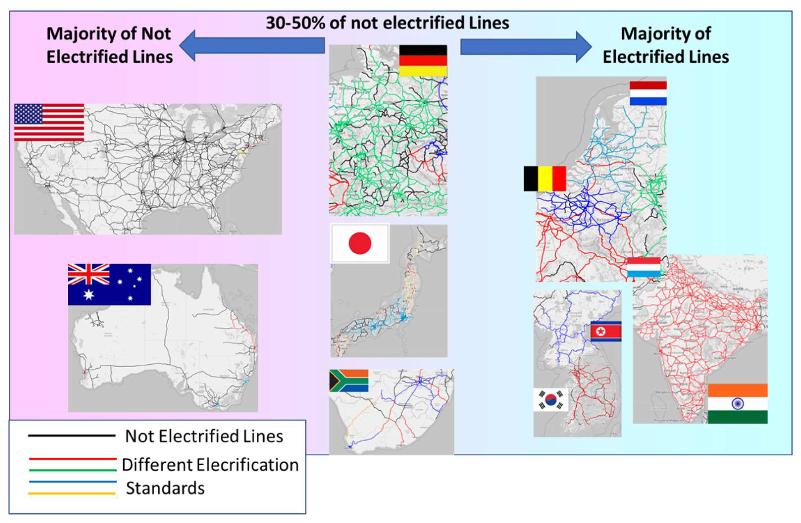
Figure 2.
Power Flow (Top) Representation and corresponding general system implementation(bottom).
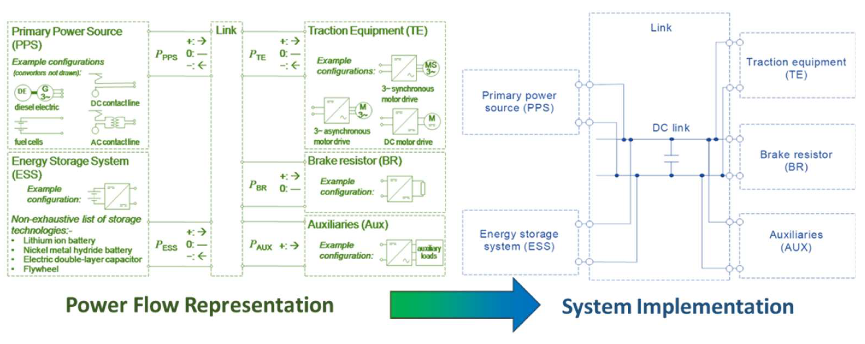
Figure 3.
the mission profile with respect of blocks/sections (3.a), mission profile of each block is treated as the summatory of five different maneuvers (3.b), scaling of the speed limits to fit an assigned timetable (3.c)
Figure 3.
the mission profile with respect of blocks/sections (3.a), mission profile of each block is treated as the summatory of five different maneuvers (3.b), scaling of the speed limits to fit an assigned timetable (3.c)
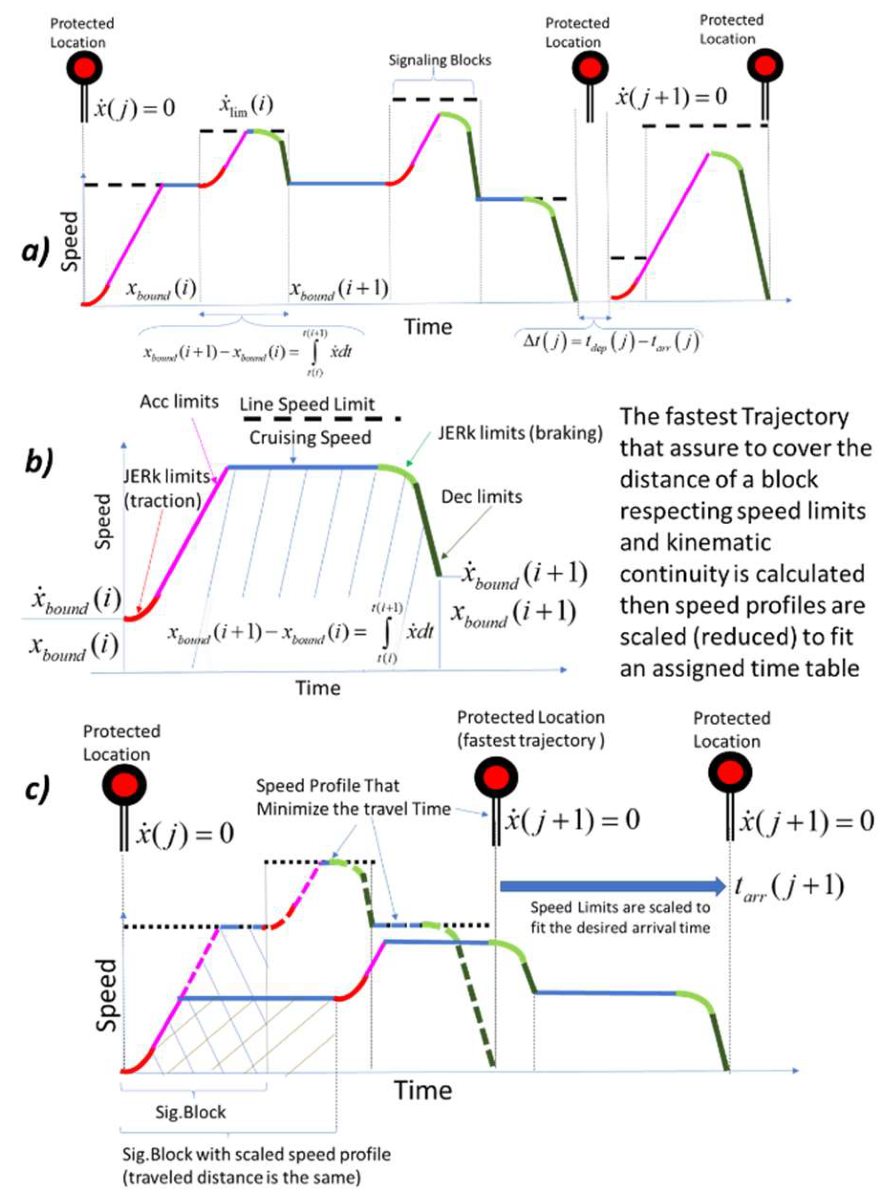
Figure 4.
Braking efforts expressed in equivalent accelerations or mass scaled braking efforts.
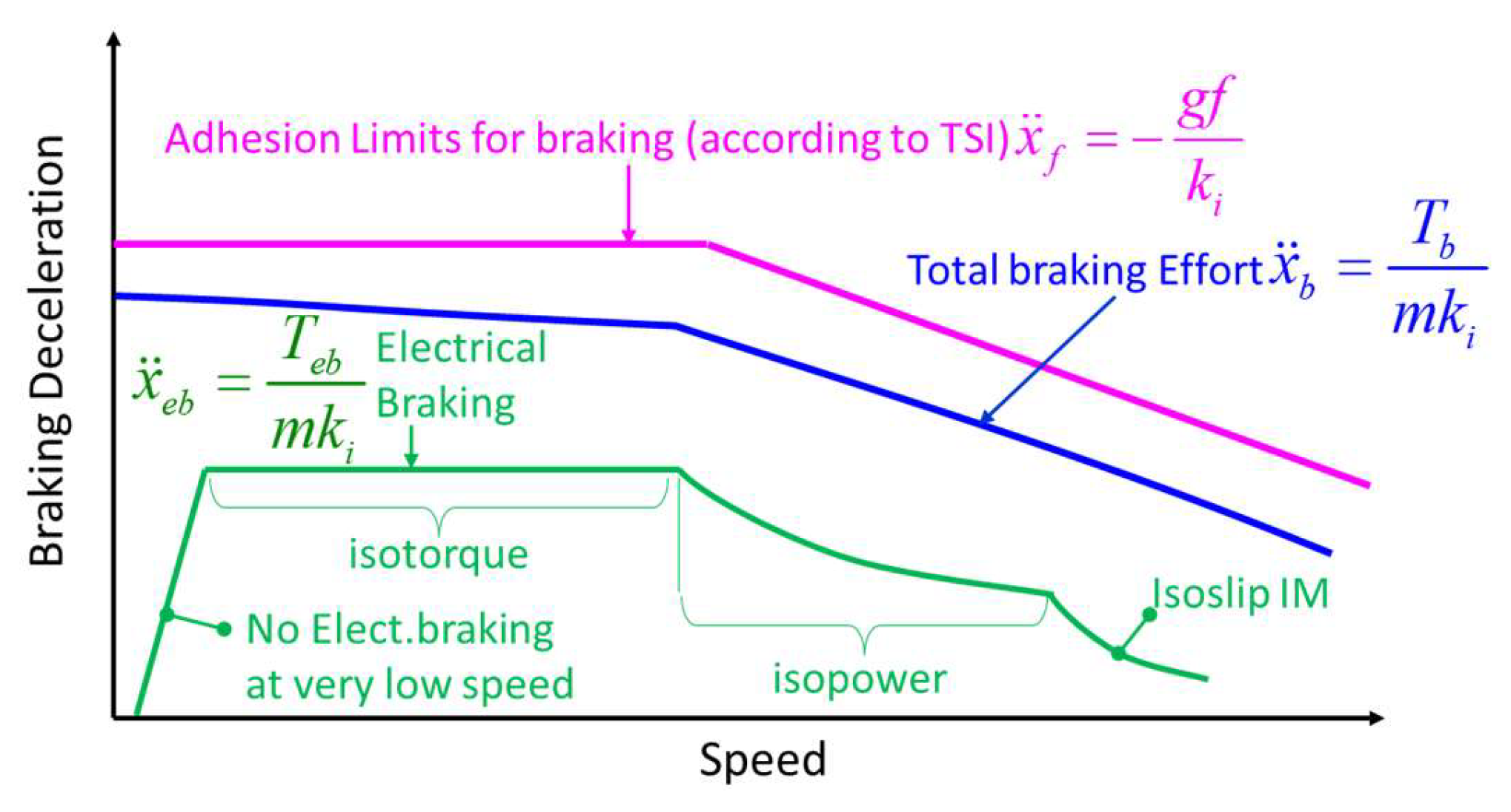
Figure 5.
Extrapolation of available volumes and load capabilities from tech documentation freely available online[20-22].
Figure 5.
Extrapolation of available volumes and load capabilities from tech documentation freely available online[20-22].
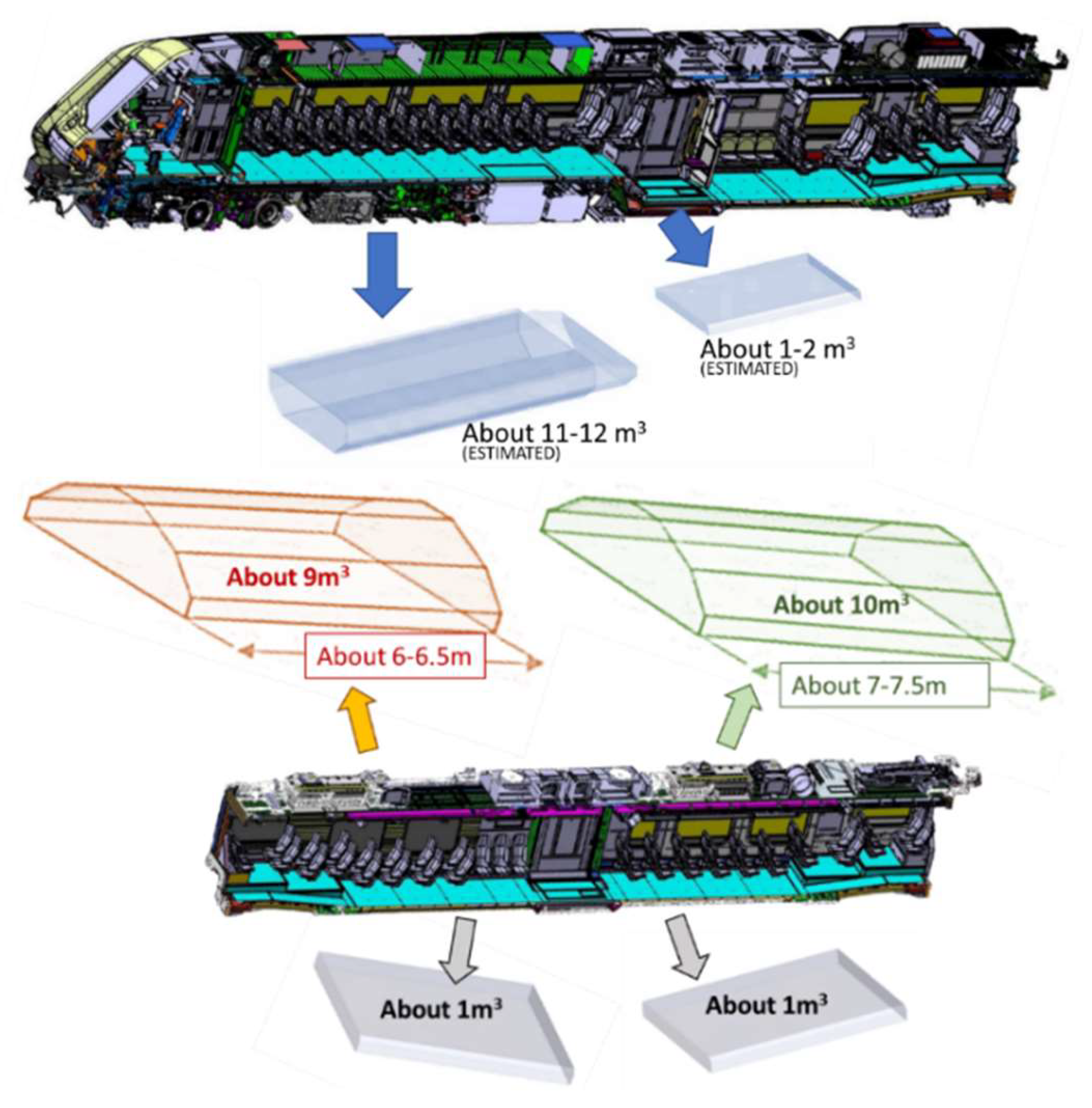
Figure 6.
Simulated Mission Profile, Map from the database Open railway Map (a), Simulated Speed Profile (b), altimetric profile of the line (c)
Figure 6.
Simulated Mission Profile, Map from the database Open railway Map (a), Simulated Speed Profile (b), altimetric profile of the line (c)
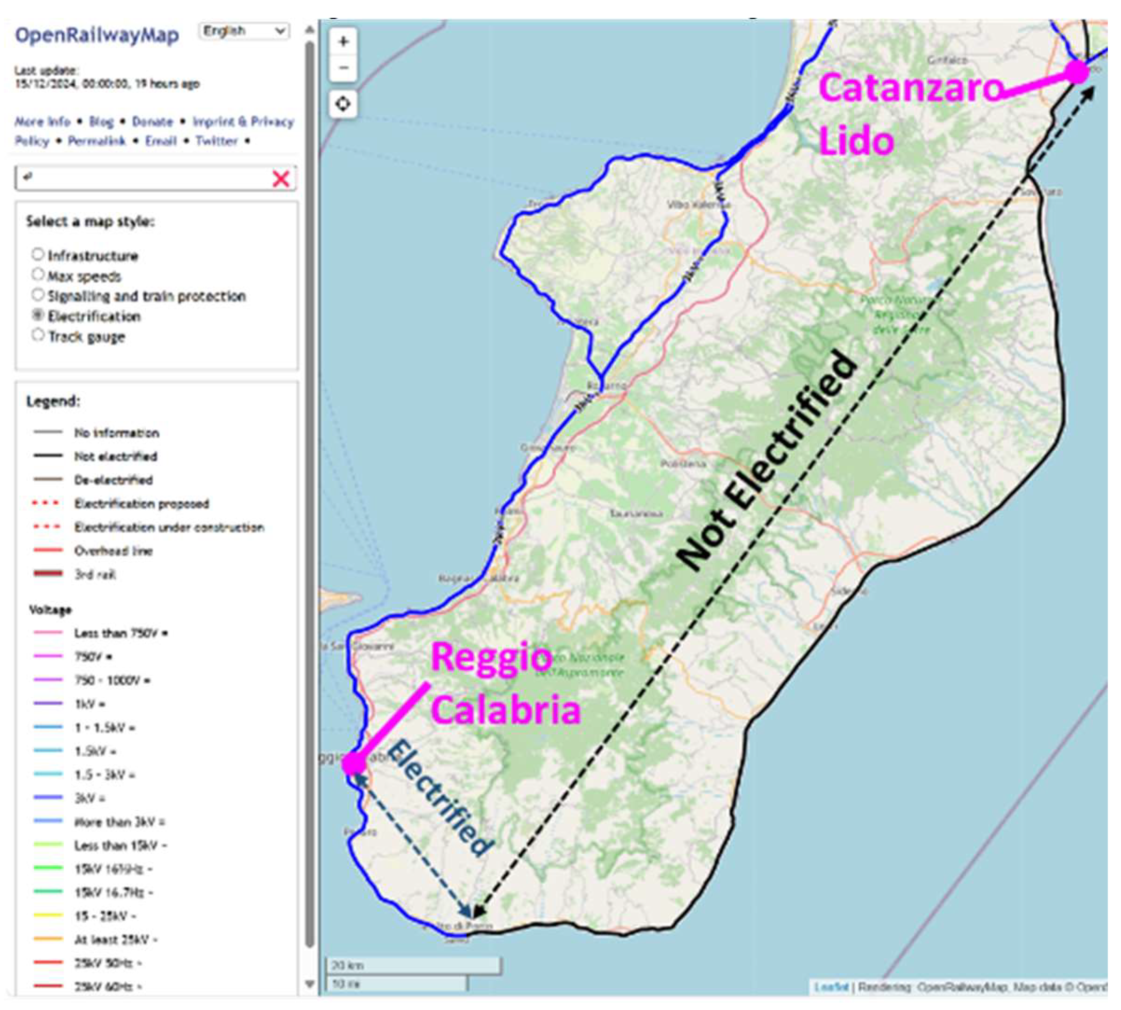
Figure 7.
Simulated Mission in terms of train speed profile, slope and imposed speed limits.
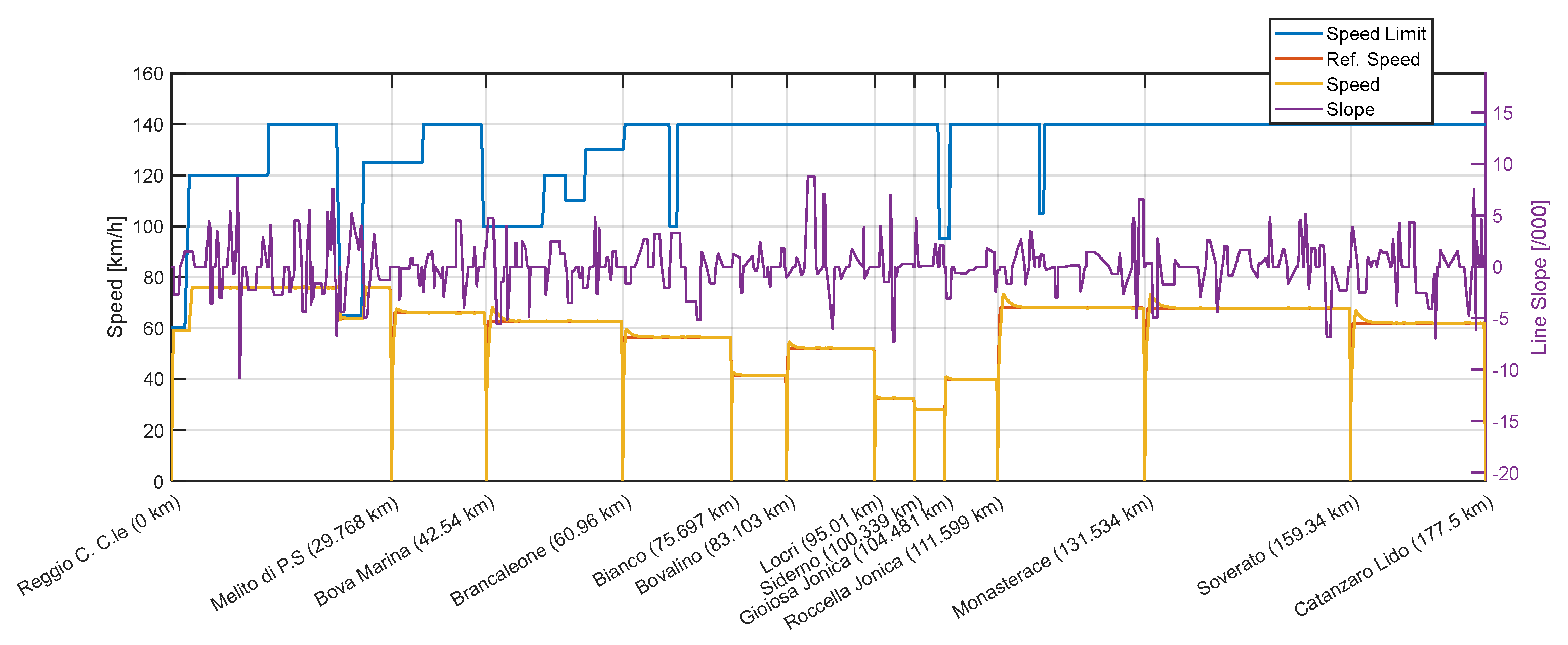
Figure 8.
Simulated combined cycle and calendar aging of different LiNMC Batteries.
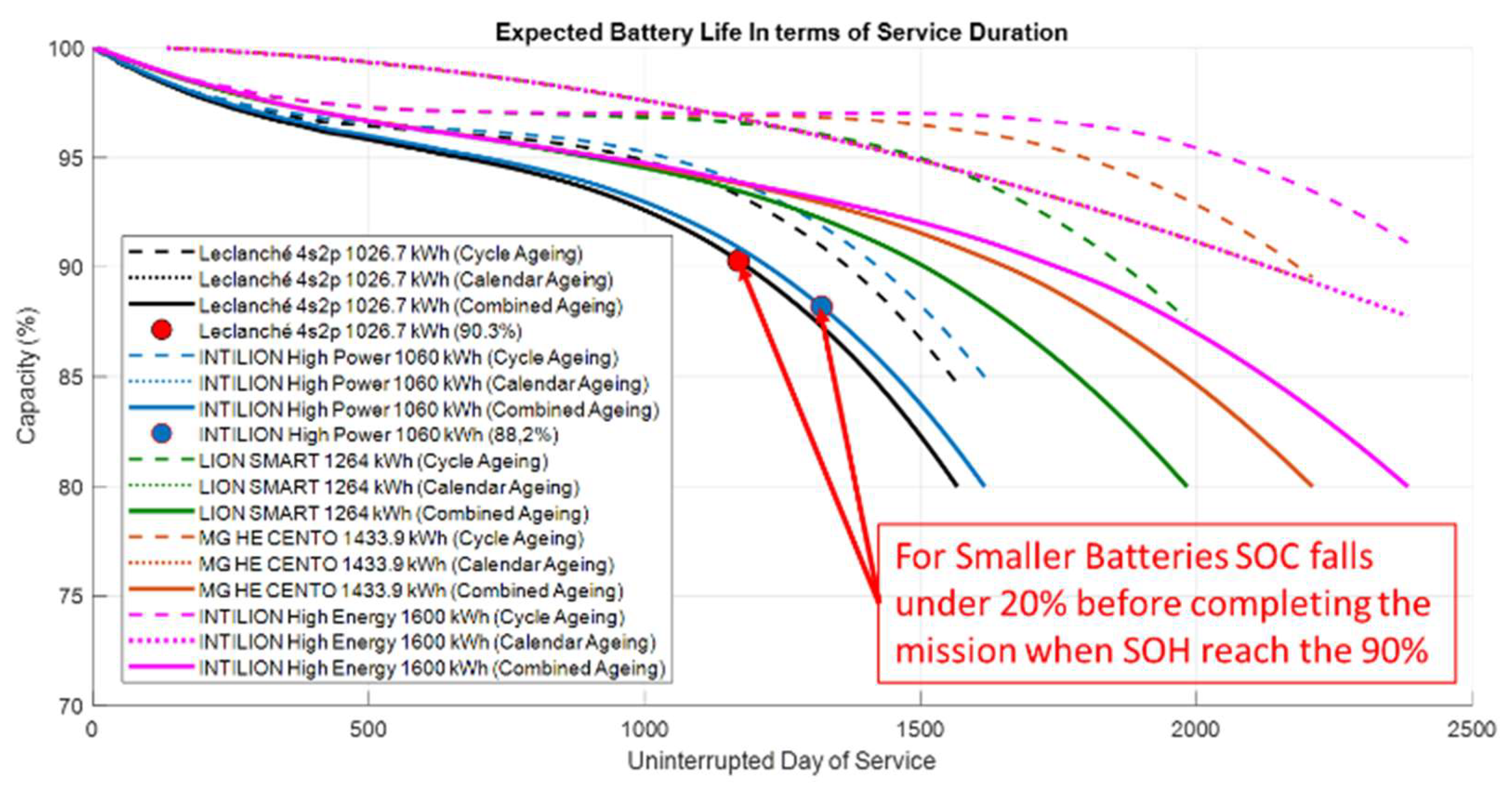
Figure 9.
Supposed Intermediate Recharge Section (simulated SOC behavior for the largest installed battery).
Figure 9.
Supposed Intermediate Recharge Section (simulated SOC behavior for the largest installed battery).
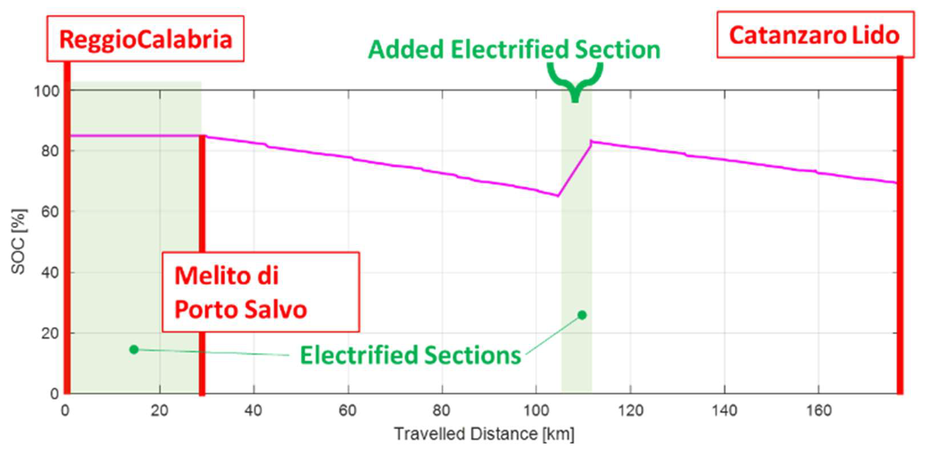
Figure 10.
Life Extension of smaller battery packs with an intermediate electrified section of 7kilometer to perform the dynamic recharge of the battery.
Figure 10.
Life Extension of smaller battery packs with an intermediate electrified section of 7kilometer to perform the dynamic recharge of the battery.
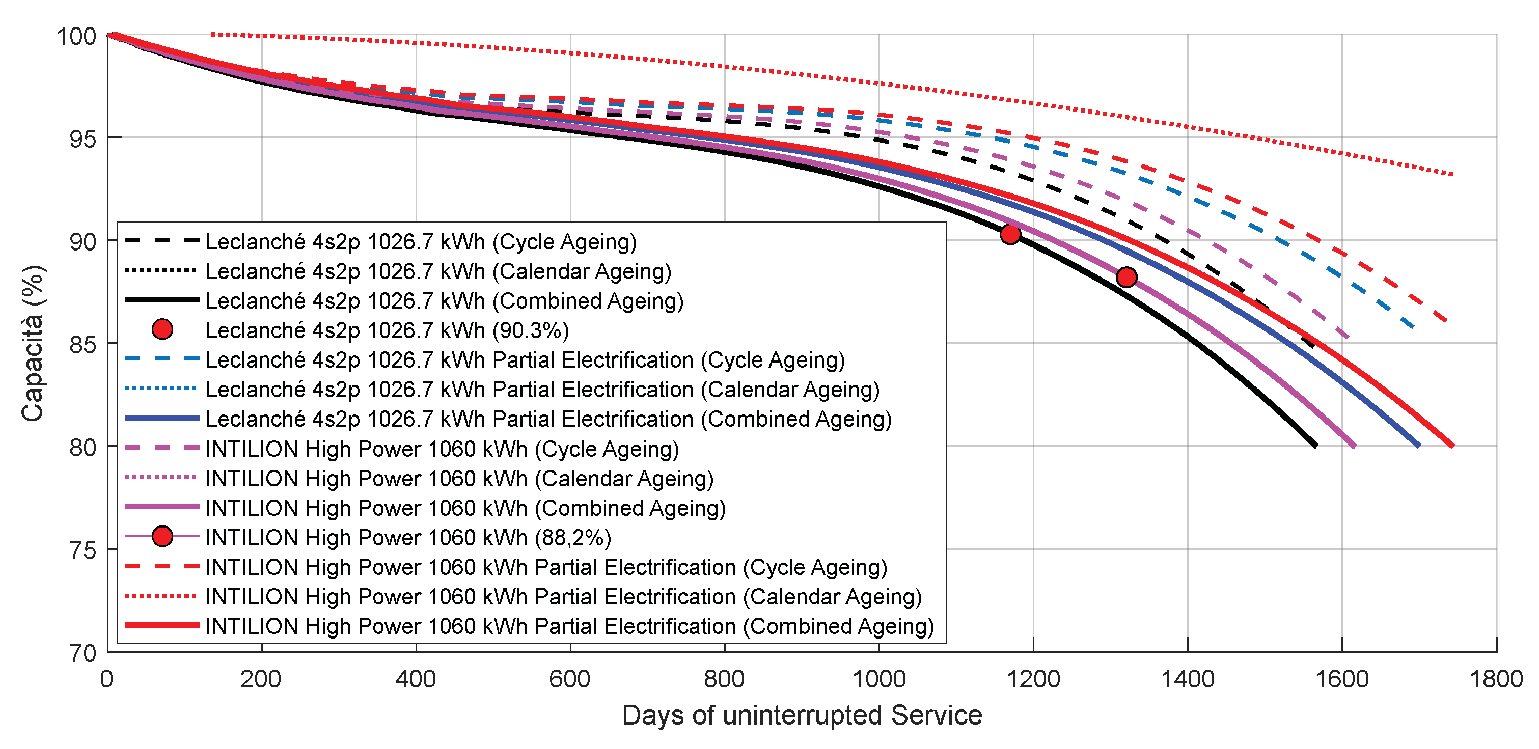
Table 2.
Mean Statistical Distribution of Auxiliary Loads in Passenger Rolling Stock
| Min | Mean | Max | |
| HVAC | 40% | 50% | 60% |
| Brake/Pneumatics | 20% | 30% | 40% |
| Lights/Illumination | 5% | 10% | 15% |
| Other Electric/Electronic Systems | 5% | 10% | 15% |
Table 3.
Main Features of the benchmark BEMU train considered for this study.
| Properties | Value |
| Train Mass (wheelset load) | 195000 kg |
| Wheelset | B0 2 2 2 B0 |
| Traction Power | 1557 kW |
| Max Traction Effort | 160 kN |
| Nominal Speed and Effort | 160 km/h, 180 kN |
| Max Speed | 140 km/h |
Table 4.
Investigated/Proposed battery packs that can be potentially installed on the benchmark test train.
Table 4.
Investigated/Proposed battery packs that can be potentially installed on the benchmark test train.
| Batt. N. | Properties |
| 1) [34] Leclanche |
Chemistry : NMC; Size [kWh] : 1026.7; Total weight : 9006 kg; Specific energy [kWh/dm3] : 113.05; Max Charge e Discharge Rate (in C) : 3C Discharge, 1C Charge. Specified cycles : 6400 (1C/1C @23°C at 80% DoD), 3600 (1C/1C @23°C at 100% DoD) |
| 2)[35] Intilion High Pow. |
Chemistry : NMC; Size [kWh]: 1060 kWh; Total weight : 9048 kg Specific energy [kWh/dm3]: 158.54; Max Charge e Discharge Rate (in C) : 3C Discharge, 3C Charge. |
| 3) [36] Lion |
Chemistry : NMC; ;Size [kWh]: 1352 kWh; Total weight : 8832 kg; Specific energy [kWh/dm3]: 151.4; Max Charge e Discharge Rate (in C) : 3C Discharge, 3C Charge.Cycle Life : > 2500 with (@25°C ambient, 1C/1C & 100% DoD) ;> 3000 with (@25°C ambient, 1C/1C & 80% DoD) ; |
| 4)[ 37] MG HE |
Chemistry : NMC;Size [kWh]: 1433.9 kWh; Total weight : 9011.8 kg; Specific energy [kWh/dm3]: 165.4;Max Charge e Discharge Rate (in C) : 1C Discharge, 1C Charge. Cycle Life : 3000 ( 75 % DOD) , 2000 ( 95% DOD) |
| 5)[35] IntilionHigh Energy |
Chemistry : NMC; Size [kWh]: 1600 kWh;Total weight : 9013.2 kg; Specific energy [kWh/dm3]: 239.2;Max Charge e Discharge Rate (in C) : 2C Discharge, 1C Charge. |
Table 5.
Simulated Mission Profile.
| Property | Feature |
| Reggio C. Catanzaro L. | Trip/ day: 2 |
| Catanzaro L. Reggio C. | Trip day : 2 |
| Recharge | Only at end of the line |
| Duration of Stops at the end of the line | 30 min for largest battery, 40-65 min for the smallest. |
| Total Km/day | Total Km : 710 km Total Km under electrified : 119 km Total km under not electrified line : 591 km |
| Total Service Time | Tot Time : 15 h for largest batt., 17 h for smallest one Time elapsed with train stopped in the railway station: 3h for largest batt. , 4h 30 min for smallest one. |
| Day of service/week | 7 |
| Added Time For Maintenance Interval | None |
Disclaimer/Publisher’s Note: The statements, opinions and data contained in all publications are solely those of the individual author(s) and contributor(s) and not of MDPI and/or the editor(s). MDPI and/or the editor(s) disclaim responsibility for any injury to people or property resulting from any ideas, methods, instructions or products referred to in the content. |
© 2025 by the authors. Licensee MDPI, Basel, Switzerland. This article is an open access article distributed under the terms and conditions of the Creative Commons Attribution (CC BY) license (https://creativecommons.org/licenses/by/4.0/).
Copyright: This open access article is published under a Creative Commons CC BY 4.0 license, which permit the free download, distribution, and reuse, provided that the author and preprint are cited in any reuse.


