
Submitted:
29 January 2025
Posted:
31 January 2025
You are already at the latest version
Abstract
The influence of residual stresses as a result of the welding process in the overall stress state of the weld joint is of great importance because they significantly affect the creation and growth of cracks, the occurrence of brittle fracture, and material fatigue. Previous experiences indicate that it would be necessary to provide an assessment of the deformation and stress state in the critical zones of the weld joints using a suitable test method, which will not endanger the structural integrity of the tested places. There are different methods for measurement of residual stress in welded constructions: destructive, semi-destructive and non-destructive. To choose one method over another, it is necessary to take into account the advantages and limitations of these techniques for practical application. This paper considers and analyses the residual stresses in the welded joint of high strength steel S960 QL. MAG welding was performed by a robot. Three methods were used to measure the residual stresses: magnetic method (MAS), X-ray diffraction method (XRD), and hole drilling method (HD). The study reveals that the highest residual stresses are measured in weld metal and heat affected zone of the weld joint what indicated all three methods but there are some significant differences between methods.
Keywords:
weld joint
; high strength steel
; residual stress
; magnetic method
; X-ray diffraction method
; hole drilling method
1. Introduction
The quenched and tempered group is the most frequently used high-strength structural steel category, and S960QL is the highest grade according to the EN 10025-6 standard, although nowadays higher-strength grades are available but not yet classified using the standard [1]. The outstanding strength properties can be particularly beneficial in case of mobile structures like vehicles, cranes, excavators etc., where due to reduced dead weight significant energy savings can be achieved and/or workloads can be increased [2]. In the production of such structures, welding is among the most important joining techniques. The S960QL steel is readily weldable. Different processes are applicable: electron beam and laser welding [3], TIG [4,5], SAW [6], and, in industrial production most often, GMAW process [1,7,8,9]. Nevertheless, welding is more complicated than in case of mild steels due to the risk of cold cracking and the decrease of toughness and strength properties in heat affected zones [2,7]. In addition, appearance of residual stress caused by restrained thermal expansion and shrinkage due to rapid local heating and subsequent cooling of the workpiece can neither be avoided nor, in case of S960QL, be reduced by post weld heat treatment as effectively as in low-strength structural steels, as according to the producers (e.g. SSAB [10], ThyssenKrupp [11]…) stress relieve temperature must not exceed 550-560 °C. Due to residual stresses, stress levels in materials can be increased. Loads resulting from superposition of workload and residual stress can easily exceed the material’s fatigue limit or even reach the yield strength. Thereby, residual stresses reduce the fatigue life of the welded joints [12]. Even moderate residual stresses (< 50 % of the yield strength) have a huge impact on the fatigue performance [13]. Therefore, as accurate knowledge as possible of residual stress-fields in the welded component is essential for prediction of its life span. Nevertheless, assessment of residual stress is often a quite difficult task. With respect to the size of the affected area, four types of residual stresses can be defined: stresses of type I, type II, type III, and type IV. [14,15,16,17]. The type I residual stresses or macro residual stresses span over several crystal grains and are balanced throughout the volume. They are called macro stresses, because a change of residual stresses of type I results in dimension change. Residual stresses of the type II or homogeneous micro residual stresses are almost homogeneous inside a microscopically small area (inside a single grain or a part of a grain) and are balanced inside of a sufficiently large group of grains. In weld joints such regions are weld metal and HAZ, where phase transformations α to γ during heating and γ to α during cooling took place WM + HAZ I. (coarse grain HAZ, fine grain HAZ and inter-critical HAZ), see Figure 1. Type III and type IV residual stresses or inhomogeneous micro residual stresses are inhomogeneous, and limited to small sub microscopic regions, i.e., several interatomic distances inside of individual grains or between crystal grain and its grain boundary. Type III residual stresses occur inside crystal grains due to presence of crystal defects (i.e. precipitates during aging, inclusions inside crystals grains what can result in higher strength of material), while type IV residual stresses occur between crystal grain and grain boundary (i.e. carbides on grain boundary to prevent creep). Total residual stresses are, in general, superimposed stresses of all four types, as shown schematically in Figure 1.
Over time, numerous different methods for measuring residual stresses have been developed. They differ not only in the accuracy and reliability of the measurement, but also size and availability of equipment, physical principle of the measurement, sampling area/volume, and consequently in the field of application. With respect to the influence on the test piece, they can be divided into three major groups: destructive, semi-destructive and non-destructive methods [15,16,18]. Destructive and semi-destructive methods rely on measurement of deformations due to the relaxation of residual stresses after some material is removed from the test piece. Sectioning and contour methods are the most common destructive techniques. Hole drilling (HD), incremental hole drilling (IHD), dip hole drilling (DHD) and ring core are the commonly used semi-destructive techniques. Non-destructive methods include X-ray diffraction (XRD), synchrotron diffraction, neutron diffraction, Raman spectrometry, ultrasonic methods, and magnetic methods. If a destructive method is applied, the test piece is destroyed. Therefore, for industrial use, non-destructive methods are more convenient. Very often also semi-destructive methods like HD and IHD are applicable, because their impact on the integrity of the test piece is small enough to be neglected, tolerated, or easily repaired [19]. For on-site testing, it is further important that portable equipment is available, like for HD, XRD, and or magnetic methods.
Over the last two decades, several reviews have been made, identifying the advantages and disadvantages of numerous methods. Most comprehensive were reviews made by Kandil et al. [20], Rossini et al. [16], and Guo et al. [21]. They established that the most popular method was the HD method followed by XRD method. Considering numerous other reports this is not surprising. The HD is the most frequently used method because it is relatively simple, quick and precise [16,22,23,24,25], it is of high theoretical maturity [21], and it is standardized in ASTM E837 [16,26,27], which is very convenient for practical use. Consequently, the method was often used to validate results of other measuring methods like XRD [28], or novel methods under development [19,22,29]. Among the disadvantages of HD and IHD, following should not be neglected: Only the macroscopic residual stresses of the type I can be determined, and the accuracy suffers in textured and inhomogeneous anisotropic microstructures [22]. Ultra high-speed drilling is necessary to introduce as little as possible stress by drilling, and if stresses are not uniform through the depth, drilling should be incremental (IHD technique) [30]. Furthermore, performance of the HD method is directly related to the quality of the strain gauge rosette and its installation, wiring, strain measuring instrument, the quality of the drilling machine and cutter, details of experimental procedure followed by the operator, and it is sensitive to stress gradients [31].
The XRD method also has many advantages. It is relatively cost-effective and widely available with portable and robotic diffractometers [27], exhibits high accuracy [21,24], and is standardized in standards EN 15305 [32] and ASTM E2860 [33]. X-rays can penetrate non-crystalline surface layers like corrosion protection maintaining reasonable accuracy [28]. Nevertheless, the presence of surface coatings, oxide layers etc. can result in reduction of intensity of diffracted X-rays, so, to assure maximum accuracy, surface should be cleaned, which is usually done almost completely non-destructive by electro polishing [34]. As the intensity of the incident X-rays decreases exponentially with the depth below the surface, XRD strain measurement is limited to very shallow surface layers [35]. Furthermore, XRD is applicable only on crystalline materials [16], whereat coarse grain size diminishes reliability and can even make the results unusable [36]. Therefore, the grain size of the workpiece should not exceed 100 μm, preferably it should be less than 30 μm [21].
In several reports, results obtained by HD and XRD were directly compared. Baig et al. [37] reported good agreement of results obtained with HD and XRD on welded samples. Jo et al. [38] measured residual stresses in spot welded high-strength steel. Results obtained by HD method were similar to those obtained by XRD. Yang et al. [28] measured residual stress in welds in ship building steel and reported that trend and magnitude of the XRD and HD results were similar.
Considering that especially on welded parts and constructions often dozens of measurements are necessary, neither HD nor XRD method is fast. Each XRD measurement takes ca. 15 min and HD measurement ca. 1 h. Therefore, despite generally good results and practical applicability of HD and XRD method there is steel room for other methods, preferably faster ones, especially for industrial use.
Suitable candidates can be found among ultrasonic and magnetic methods. They are easy to use, fast, and low-cost methods but they have low resolution [Rossini-2012-14]. At present, the accuracy of general equipment for ultrasonic residual stress measurement can reach approximately ± 30 MPa. Among magnetic methods, two methods based on magnetoelastic effect are relatively widespread. Barkhausen emission (BE, also known as BNE or MBE) which measures electromagnetic pulses (Barkhausen noise) caused by stress-induced irreversible domain wall movements under an applied magnetic field. BE is particularly sensitive to the microstructure and mechanical properties of the material and is sensitive to surface quality - preparation [39]. The other is magnetic anisotropy system (MAS) which is based on stress induced magnetic anisotropy and measures magnetic permeability (the result of measurement is the subtraction of principal stresses σ1 − σ2).
Probe consists of two solenoids that are orthogonally positioned. Solenoids have cores made of magnetic material, in order to ensure higher magnetic excitation. The device measures magnetic permeability in the plain along the chosen direction due to the core orientation from one pole to another. Probe position (orientation), which yields maximum stress, corresponds to maximum principal stress σ1. Principal stress σ2 stress is obtained when probe is rotated for 90°. Magnetic permeability is proportional to the deformation which is itself proportional below 0.8 yield stress. If this value is exceeded, the relation follows the so-called "S" curve and nonlinear behaviour, which is determined with calibration, should be taken into account [40].
For MAS the surface of the material requires no special treatment except that it must be flat.
In principle, MAS is accurate, and uncertainties are in order of 1 MPa, while for harder materials such as fully pearlitic or martensitic steels the uncertainties become larger, typically a few tens of MPa [41]. Also textured microstructures increase uncertainty. Bešević et al. [40] applied this method on cold formed steel and established accuracy within ± 40 MPa. To increase accuracy, it is critical to obtain calibration curves with calibration samples similar to the actual component to be tested [20,21,40,41]. For welded test pieces this means, that calibration samples must consist of weld, HAZ and base metals, and they must be welded with the same process and welding parameters as the real test piece [30]. Authors considered MAS as a comparative method [40,42], as a possibility to reduce measurement costs by combining MAS and HD - first, it is necessary to perform magnetic method measurements on as many points as possible, and then perform a check of residual stresses on some measurement points with rosette strain gauge method.
No comparisons of results obtained with MAS and XRD on the same test piece or direct comparison of results obtained with more than two methods could be found in the open literature.
Due to the small allowable heat input, steep microstructural gradients can be expected in S960-welds, which reduce the reliability of the results for most residual stress measurement methods. Consequently, the importance of comparing results obtained by different methods increases.
2. Materials and Methods
2.1. Material and Welding
15 mm thick steel plates made of high-strength S960QL steel according to EN 10025-6:2019+A1:2023 [45] were used as the base material. The chemical composition of the steel is given in Table 1, and the basic mechanical properties in Table 2.
Two equally sized plates 15 mm × 160 mm × 700 mm were welded with MAG process with a solid metal wire (135 according to EN ISO 4063:23 [46]). The geometry of the single-V butt weld was as follows: plate thickness t = 15 mm groove angle α = 50°, root opening b = 3 mm, and root face u = 1 mm, Figure 2a. The sequence of passes is shown in Figure 2b.
The filler material was a solid wire φ1.0 mm BÖHLER X 90-IG (G 89 6 M21 Mn4Ni2CrMo) according to EN ISO 16834-A [47]. Chemical composition is given in Table 3.
Shielding gas was M21 according to EN ISO-14175:2008 [EN-ISO-14175:2008] containing 82% Ar + 18 % CO2. High argon content reduced spraying and assured low level of oxidation. The CO2 stabilized the electric arc and increased penetration. Preheating temperature was calculated according to EN 1011-2:2001 [48], Annex C, Method B.
The welding was performed in the industrial environment by a robot OTC FD-V8L (OTC Daihen Europe, Mönchengladbach, Germany) and welding machine WelBee P500L (Daihen Varstroj d.d., Lendava, Slovenia). The welding parameters are given in Table 4.
2.2. Tensile Test
The tensile test is a mechanical test, in which the specimen is loaded with a uniaxial load, which gradually increases. The test was done according to standard EN ISO 6892-1:2019 by using method B [49] on the servo hydraulic Amsler 559/594 universal testing machine (Amsler Prüfmaschinen A.G., Merishausen, Switzerland — now Amsler Prüfsysteme, Neftenbach, Switzerland). Two specimens were taken out from the welded plate so that the weld was in the middle of the gauge length. The fracture was expected to occur in the zone of the welded joint. Figure 3 shows the geometry of the tensile specimens, and Figure 4 shows tensile specimens ready for testing.
2.3. Residual Stress Measurement
Residual stress (RS) was measured on predefined locations along a line perpendicular to the welding direction, Figure 4. At each location, RS were measured first by MAS, then by XRD, and finally by HD. Coordinates are of measuring points are given in Table 5.
2.3.1. Magnetic Method - MAS
A SMMT-1 device was used (E. O. Paton Electric Welding Institute, Kiev, Ukraine), Figure 5a. The probe measures the average voltage value of an area with a diameter of 25 mm to a depth up to 0.5 mm. For determination of the calibration curve, a welded flat specimen having a cross-section of 25.1 mm × 7.5 mm was used, which was loaded up to Rp0.2, Figure 5b. Calibration was performed on a universal Serservo hydraulic testing machine Amsler 559/594 (Amsler Prüfmaschinen A.G., Merishausen, Switzerland — now Amsler Prüfsysteme, Neftenbach, Switzerland).
Calibration curve signal voltage vs tensile stress is presented in Figure 6.
2.3.2. X-Ray Diffraction Method – XRD
Before measuring, the surface layer was removed by electropolishing. In order to successfully perform electropolishing, it is important to choose the correct electrolyte and electropolishing parameters. The EP3 (Pulstec Industrial Co., Ltd., Hamamatsu, Japan) device was used for electropolishing. The electropolishing anode (+) is a magnet that is placed on the surface of the sample to be electropolished. The cathode (−) represents the electrode of the device EP3. The electrolyte closes the current loop between the electrodes. The depth of electropolishing depends on the condition of the surface and the material and is about ~100 μm. That is, the total depth of electropolishing depends on the area of material electropolishing. Electropolishing was performed on a surface of Ø 5 mm, with a 10 % NaCl solution in water with a current of 0.6 A for 3 minutes, polishing speed 40 μm/min. For measurements, a Pulstec U-X360 device was used (Pulstec Industrial Co., Ltd., Hamamatsu, Japan), Figure 7. It works with a fixed angle of incident X-rays. A circular mask for X-rays (a collimator) limits the irradiated surface area to a diameter of 2 mm. The irradiated surface is marked by a laser pointer which allows precise selection of analysed area. All deflected X-rays are collected by a two-dimensional detector during only one exposure, enabling the image of the entire Debye-Scherrer ring where the final value of residual stress in the direction of measuring is automatically determined. Residual stresses were measured in two directions, parallel and perpendicular to the welding direction.
2.3.3. Hole Drilling Method – HD
The most widely used and most reliable modern technique for measuring residual stress is the method of "hole drilling". As the accuracy and reliability of this method have been experimentally proven (the accuracy of this method is ± 8 %), it is as standardized as Standard ASTM E837. In this method, the deformation sensor (strain gauge rosette) is first glued (Z70 glue is used - a superglue with extremely fast drying time) to the surface of the test part. For the centring the drill and drilling a hole, a MTS3000 device was used (SINT Technology S.r.l, Calenzano, Italy), Figure 8. The depth of drilling was 1.0 mm. Strain gauges - rosettes 1-RY61-1.5/120 with a hole diameter 1.6 mm were used (Hottinger Baldwin Messtechnik GmbH, Darmstadt, Germany). For data acquisition, a Spider 8 acquisition system, and for evaluation the EVAL 7 software were used (both from SINT Technology s.r.l, Calenzano, Italy).
2.4. Optical Microscopy
The microstructures were analysed in three areas of the weld join, in the weld reinforcement (weld metal, WM), in the heat affected zone (HAZ) and in the unaffected base material (BM), Figure 9. A Nikon Epiphot 300 optical microscope (Nikon, Tokio, Japan) equipped with an Olympus DP-12 digital camera (Olympus, Boston, MA, USA) was used.
3. Results
3.1. Tensile Test Results
The tensile test was performed on two specimes: TT-1 and TT-2. Table 6 shows the results of the tensile test. In both cases, the rupture occurred in the area of base material.
3.2. Results of Magnetic Method
Before measuring, the plate was demagnetized. Then the stresses in the characteristic directions were measured, the longitudinal and the transverse stresses in the different directions (M1, M2, M3, M4). The principal residual stresses in the longitudinal (σ1) and transversal (σ2) directions are obtained as the arithmetic mean of two measurements in different directions along with the calibration signal. The subtraction of principal stresses is shown in the diagram in Figure 10. Also, measured and calibrated residual stress values using the magnetic method are given in Table 7.
3.3. Results of X-Ray Diffraction Method
3.4. Results of Hole Drilling Method
Individual measured values were read for all three measuring gauges in the rosette. Individual diagrams for measuring locations in different zones M1 – base material (Figure 13), M4 – heat affected zone (Figure 14), and M5 – weld metal (Figure 15) are shown: a) deformations (ε1, ε2, and ε3) per drilling depth, b) principal residual stresses (σ1 and σ2) and angle of residual stresses (β) per drilling depth, and c) longitudinal (σlong), transverse (σtran) and shear (τxy) stresses per drilling depth.
Table 9 shows the results of deformations, angle of principal stresses, principal stresses and longitudinal, transverse and shear stresses at a depth of 1 mm of drilling a hole. The diagram in Figure 16 shows the subtraction of longitudinal and transverse stress for all nine measuring points at a drilling depth of 1 mm.
3.5. Microstructure
Three different location were observed: base materials, heat affected zone and weld metal (Figure 17). Figure 17a shows the microstructure of the base material where a fine grain martensitic microstructure can be observed. The microstructure on the left side of the Figure 17b is the coarse grain heat affected zone, and on the right side is the weld metal. In the coarse grain heat affected zone there is lath martensite with long laths, which formed during cooling of the weld joint. Figure 17c shows weld metal which has dendritic fine grain martensitic microstructure.
4. Discussion
In this paper, residual stresses were measured with three different methods: MAS, XRD, and HD methods. Each of these methods is specific and has its advantages and disadvantages. Also, when comparing these three methods, the results deviate in certain areas for several reasons. The main difference in measurements is that each method measures residual stresses at differently large areas and different depths and averages the results. HD method covered a volume of 5.13 mm in radius, and up to 1 mm deep. MAS method measured inside a cylinder with diameter 25 mm and depth 0.5 mm, while XRD method measured inside a cylinder with diameter 1 mm and depth up to 0.010 mm under the surface. Another difference in measurements is that each of these three methods measures different types of residual stresses. Only type I can be measured with the HD method, types I and II with the HD method, and type I, II, III and IV of residual stresses with the XRD method. Also, each method provides a different result, and in order to be able to compare them, we have to harmonize them.
As it is known that the XRD method gives direct residual stresses in the longitudinal and transverse directions separately, results of the HD method must be adopted to compare the HD and XRD methods as shown in Figure 18 and Figure 19. With the HD method, we get the principal stresses and the direction/angle of the principal stresses, and to get the residual stresses in the direction we want, Moore circles are used. Thereby, a direct comparison of the residual stresses σlong (Figure 18) and σtran (Figure 19) is possible. The biggest differences between methods were noted in WM and HAZ because the XRD method has the disadvantage that when it encounters a coarse grain the scattering of results is significant, as it was observed also in the case of S960QL steel. The difference is also in type of residual stresses which both methods measure (HD – type I, XRD – type I + type II).
In order to compare all three methods at once, all residual stress results should be converted to give the subtractions of longitudinal and transverse stress for each measurement point. In the MAS method, the disadvantage is that the residual stress is obtained by the subtraction of the principal stresses. By measuring the principal stresses, we can get in one direction the stress in the plus and the other in the minus which results in obtaining large residual stresses, which is not favourable, and makes interpretation of the results more difficult. A comparison of all three methods as a subtraction of longitudinal and transverse residual stress (σlong – σtran) is shown in Figure 20.
The difference is also in type of residual stresses which each of these methods measures (HD – type I, XRD – type I + type II, MAS – type I + type II + type III + type IV) and the sizes of areas where each of these method measure. The biggest difference in residual stresses is in areas of high gradients of residual stresses, due to averaging of the result on the whole measuring area (HD – area of the grids of strain gauges in rosette – diameter of the rosette 5.13 mm, and 1 mm in depth, XRD – 1 mm2 and MAS – circle with diameter 25 mm, and 0.5 mm in depth). The areas with high gradients of residual stresses are HAZ and WM, while in BM there are no areas exhibiting so high gradients of residual stresses, and therefore, no significant differences in results occur (Figure 20).
5. Conclusions
The superposition of the welding residual stresses with working stresses caused by operating condition can lead to extending of the defects or cracks initiation and their propagation up to the up to the point where the structure needs to be repaired or even withdrawn from use. Therefore, knowing the residual stresses is very important for designing and prediction of the life of welded structures. In this paper, residual stresses were measured by using three different methods on V- shaped butt weld joint. These methods were the magnetic method, X-ray diffraction method, and the hole drilling method. At the end results of the residual stresses were compared. The highest tensile residual stresses were obtained in the HAZ and the weld metal. In other areas (base material), tensile or compressive residual stresses appeared. Comparison of the residual stress measurements in the same measuring point needs to be done by taking into account measuring volume and depth where residual stresses are averaged during measurement, and what exactly each of methods really measure (types of residual stresses). Consequently, comparison of the methods is not so easy. The additional difficulties are microstructural changes in HAZ, and newly formed coarse columnar grains in weld metal, which both significantly decrease the reliability of the XRD method. Nevertheless, with appropriate adaptation of results, direct comparison of all three methods is possible. In future work, we plan to use the same three methods of residual stress measurement, mutual comparison, on a welded joint of high-strength anti-ballistic steel.
Author Contributions
Conceptualization, T.V., and M.M.; methodology, G.L.; validation, M.M., and T.V.; formal analysis, M.M., N.G., B.K, and G.L.; investigation, M.M., and B.K.; resources, T.V.; data curation, M.M.; writing—original draft preparation, M.M.; writing—review and editing, G.L.; visualization, T.V.; supervision, T.V.; project administration, T.V.; funding acquisition, T.V. All authors have read and agreed to the published version of the manuscript.
Funding
This research was funded by the Slovenian Research and Innovation Agency, Research Core Funding (No. P2-0120) and projects BI-BA/19-20-036, BI-ME/23-24-019 and BI-BA/24-25-041.
Data Availability Statement
Data are contained within the article.
Conflicts of Interest
The authors declare no conflicts of interest. The research was conducted in the absence of any commercial or financial relationships that could be construed as a potential conflict of interest.
References
- Sisodia, R. P. S.; Gáspár, M., An Approach to Assessing S960QL Steel Welded Joints Using EBW and GMAW. Metals-Basel 2022, 12, (4).
- Lukács, J.; Gáspár, M., Fatigue crack propagation limit curves for high strength steels and their application for engineering critical assessment calculations. Adv Mater Res-Switz 2014, 891-892, 563-568.
- Sága, M.; Blatnická, M.; Blatnicky, M.; Dizo, J.; Gerlici, J., Research of the Fatigue Life of Welded Joints of High Strength Steel S960 QL Created Using Laser and Electron Beams. Materials 2020, 13, (11).
- Hensel, J.; Nitschke-Pagel, T.; Dilger, K.; Schönborn, S., Effects of Residual Stresses on the Fatigue Performance of Welded Steels with Longitudinal Stiffeners. Mater Sci Forum 2014, 768-769, 636-+.
- Schaupp, T.; Schroepfer, D.; Kromm, A.; Kannengiesser, T. Welding Residual Stress Distribution of Quenched and Tempered and Thermo-Mechanically Hot Rolled High Strength Steels. Residual Stresses Ix 2014, 996, 457–462. [Google Scholar] [CrossRef]
- Türker, M. The Effect of Welding Parameters on Microstructural and Mechanical Properties of HSLA S960QL Type Steel with Submerged Arc Welding. Journal of Natural and Applied Sciences 2017, 21, 673–682. [Google Scholar] [CrossRef]
- Gáspár, M.; Balogh, A. GMAW experiments for advanced (Q+T) high strength steels. Production Processes and Systems 2013, 6, 9–24. [Google Scholar]
- Madej, K.; Jachym, R. Welding of High Strength Toughened Structural Steel S960QL. Materials Science and Welding Technologies 2017, 2017, 6–16. [Google Scholar] [CrossRef]
- Schubnell, J.; Carl, E.; Farajian, M.; Gkatzogiannis, S.; Knödel, P.; Ummenhofer, T.; Wimpory, R. C.; Eslami, H. Residual stress relaxation in HFMI-treated fillet welds after single overload peaks. Welding in the World 2020, 64, 1107–1117. [Google Scholar] [CrossRef]
- companies, S. g. o. STRENX® Performace Steel - STRENX® 960 E/F https://www.ssab.com/api/sitecore/Datasheet/Get?key=59e738903b6247a3b68df07d49f40239_en (2025-01-27).
- AG, T. STRENX® Performace Steel - STRENX® 960 E/F https://www.thyssenkrupp-steel.com/media/content_1/publikationen/produktinformationen/gbq/april_2021/gbq-0055-s960ql-tkse-cpr-01042021.pdf (2025-01-27).
- Goss, C.; Marecki, P.; Grzelak, K. Fatigue life of S960QL steel welded joints. Biuletyn WAT 2014, 63, 13–19. [Google Scholar] [CrossRef]
- Hensel, J.; Nitschke-Pagel, T.; Rebelo-Kornmeier, J.; Dilger, K. Experimental investigation of fatigue crack propagation in residual stress fields. Procedia Engineer 2015, 133, 244–254. [Google Scholar] [CrossRef]
- Garstka, T.; Szota, P.; Mroz, S.; Stradomski, G.; Grobarczyk, J.; Gryczkowski, R., Calibration Method of Measuring Heads for Testing Residual Stresses in Sheet Metal Using the Barkhausen Method. Materials 2024, 17, (18).
- Withers, P. J.; Bhadeshia, H. K. D. H., -: Residual stress part 1 -: Measurement techniques. Mater Sci Tech-Lond 2001, 17, (4), 355-365.
- ossini, N. S.; Dassisti, M.; Benyounis, K. Y.; Olabi, A. G., Methods of measuring residual stresses in components. Materials & Design 2012, 35, 572-588.
- Salvati, E.; Korsunsky, A. M. An analysis of macro- and micro-scale residual stresses of Type I, II and III using FIB-DIC micro-ring-core milling and crystal plasticity FE modelling. Int J Plasticity 2017, 98, 123–138. [Google Scholar] [CrossRef]
- Glaissa, M. A. A.; Asmael, M.; Zeeshan, Q. Recent Applications of Residual Stress Measurement Techniques for FSW Joints: A Review. J Kejuruter 2020, 32, 1–15. [Google Scholar] [CrossRef]
- Arabul, E.; Lunt, A. J. G., A Novel Low-Cost DIC-Based Residual Stress Measurement Device. Appl Sci-Basel 2022, 12, (14).
- Kandil, F.A; Lord, J.D; Fry, A.T; Grant, P.V. A Review of Residual Stress Measurement Methods - A Guide to Technique Selection; NFL Report MATC(A)O4; National Physical Laboratory, Teddington - Materials Centre: Teddington, Middlesex, UK, 2001; pp. 1–42. [Google Scholar]
- Guo, J.; Fu, H. Y.; Pan, B.; Kang, R. K. Recent progress of residual stress measurement methods: A review. Chinese J Aeronaut 2021, 34, 54–78. [Google Scholar] [CrossRef]
- Aminforoughi, B.; Degener, S.; Richter, J.; Liehr, A.; Niendorf, T., A Novel Approach to Robustly Determine Residual Stress in Additively Manufactured Microstructures Using Synchrotron Radiation. Adv Eng Mater 2021, 23, (11).
- Pardowska, A.M.; Price, J.W.H.; Finlayson, T.R. Poređenje tehnika merenja zaostalih napona primenjljivih na zavarenim čeličnim delovima, Comparison Of Residual Stress Measurements Techniques Applicable To The Steel Welded Components (in translation). Zavarivanje i zavarene konstrukcije, 2009. [Google Scholar]
- Rahimi, S.; Violatos, I. Comparison Between Surface and Near-Surface Residual Stress Measurement Techniques Using a Standard Four-Point-Bend Specimen. Exp Mech 2022, 62, 223–236. [Google Scholar] [CrossRef]
- Schajer, G. S.; Prime, M. B.; Withers, P. J. Why Is It So Challenging to Measure Residual Stresses ? Exp Mech 2022, 62, 1521–1530. [Google Scholar] [CrossRef]
- ASTM International, ASTM E837-20 - Standard Test Method for Determining Residual Stresses by the Hole-Drilling Strain-Gage Method. ASTM International: West Conshohocken, PA, 19428-2959 USA 2020; pp 1-16.
- Deveci, M. Stresstech Bulletin 12: Measurement Methods of Residual Stresses. https://www.stresstech.com/stresstech-bulletin-12-measurement-methods-of-residual-stresses/ (2025-01-23).
- Yang, Y. P.; Dull, R.; Huang, T. D.; Rucker, H.; Harbison, M.; Scholler, S.; Zhang, W.; Semple, J., Development of Weld Residual Stress Measurement Method for Primed Steels. Proceedings of the Asme Pressure Vessels and Piping Conference, 2017, Vol 6b 2017.
- Wang, Z. Y.; Zhou, H. B.; Zhou, W. W.; Li, Z. Q.; Ju, X.; Peng, Y. C.; Duan, J. A. Experimental and numerical investigation of residual stress and post-weld-shift of coaxial laser diodes during the optoelectronic packaging process. Welding in the World 2023, 67, 63–76. [Google Scholar] [CrossRef]
- Engineering Principles-Welding and Residual Stresses. Cooke, K., Cozza, R., C., Ed. IntechOpen: Rijeka, Croatia, 2022; p 338.
- Schajer, G. S.; Whitehead, P. S. Hole Drilling and Ring Coring. Practical Residual Stress Measurement Methods 2013, 29–64. [Google Scholar]
- The European Committee for Standardization, EN 15305:2008: Non-destructive Testing - Test Method for Residual Stress analysis by X-ray Diffraction. European Committee for Standardization (CEN): Brussels, Belgium, 2008; pp 1-85.
- ASTM International, ASTM E2860-20 - Standard Test Method for Residual Stress Measurement by X-Ray Diffraction for Bearing Steels. ASTM International: West Conshohocken, PA, 19428-2959 USA 2020; pp 1-19.
- Yang, Y. P.; Huang, T. D.; Rucker, H. J.; Fisher, C. R.; Zhang, W.; Harbison, M.; Scholler, S. T.; Semple, J. K.; Dull, R. Weld Residual Stress Measurement Using Portable XRD Equipment in a Shipyard Environment. J Ship Prod Des 2019, 35, 231–240. [Google Scholar] [CrossRef]
- Technical note TN-503-6: Measurement of Residual Stresses by the Hole-Drilling Strain Gage Method; Vishay Precision Group, Micro-Measurements: North Carolina, USA, 2010; pp. 19–33.
- Belassel, M. Residual Stress Measurement using X-Ray Diffraction Techniques, Guidelines and Normative Standards. SAE International journal of meterials and manufacturing 2012, 5, 352–356. [Google Scholar] [CrossRef]
- Baig, M.; Khan, S. M. A.; El Rayes, M. M.; Seikh, A. H. Evaluation of residual stresses present in spirally welded API grade pipeline steel using the hole drilling method. Mater Test 2017, 59, 258–264. [Google Scholar] [CrossRef]
- Jo, W.; Woo, I.; Mikami, Y.; An, G., Residual Stress Characteristics in Spot Weld Joints of High-Strength Steel: Influence of Welding Parameters. Appl Sci-Basel 2024, 14, (24).
- Wang, L. T.; Xu, C. J.; Feng, L. B.; Wang, W. J. A Survey of the Magnetic Anisotropy Detection Technology of Ferromagnetic Materials Based on Magnetic Barkhausen Noise. Sensors-Basel 2024, 24. [Google Scholar]
- Besevic, M. Experimental investigation of residual stresses in cold formed steel sections. Steel Compos Struct 2012, 12, 465–489. [Google Scholar] [CrossRef]
- Buttle, D., J.; Moorthy, V.; Shaq, B. A National Measurement Good Practice Guide No. 88 - Determination of Residual Stresses by Magnetic Methods; National Physical Laboratory: Teddington, UK, 2006; pp. 1–52. [Google Scholar]
- Islamović, F.; Gačo, D.; Hodžić, D. ; E., B., Determination of Stress-Strain State on Elements of Cylindrical Tank Structure. In th scientific conference on defensive technologies OTEH 2020, Lisov M., R. L., Ed. The Military Technical Institute, Ratka Resanovića: Belgrade, Serbia, 2020; pp 429-435.
- Suominen, L.; Khurshid, M.; Parantainen, J. Residual stresses in welded components following post-weld treatment methods. Fatigue Design 2013, International Conference Proceedings 2013, 66, 181–191. [Google Scholar] [CrossRef]
- Raghawendra, P. S. S.; Gáspár, M.; Sepsi, M.; Mertinger, V. Dataset on full width at half maximum of residual stress measurement of electron beam welded high strength structural steels (S960QL and S960M) by X-ray diffraction method. Data Brief 2021, 38. [Google Scholar]
- The European Committee for Standardization, EN 10025-6:2019+A1:2023: Hot rolled products of structural steels - Part 6: Technical delivery conditions for flat products of high yield strength structural steels in the quenched and tempered condition. European Committee for Standardization (CEN): Brussels, Belgium, 2023; pp 1-28.
- The European Committee for Standardization, EN ISO 4063:2023: Welding, brazing, soldering and cutting - Nomenclature of processes and reference numbers. European Committee for Standardization (CEN): Brussels, Belgium, 2023; pp 1-25.
- International Organization for Standardization, ISO 16834:2012-Welding consumables — Wire electrodes, wires, rods and deposits for gas shielded arc welding of high strength steels — Classification. International Organization for Standardization: Geneva, Switzerland, 2012; pp 1-14.
- The European Committee for Standardization, EN 1011-2:2001: Welding - Recommendations for welding of metallic materials - Part 2: Arc welding of ferritic steels. The European Committee for Standardization (CEN): Brussels, Belgium, 2001; pp 1-57.
- The European Committee for Standardization, EN ISO 6892-1:2019: Metallic materials - Tensile testing - Part 1: Method of test at room temperature. European Committee for Standardization (CEN): Brussels, Belgium, 2019; pp 1-87.
Figure 1.
Total residual stress distribution along several crystal grains of a polycrystalline material and their partitioning in type I (σRS,I. - macro residual stresses), type II (σRS,II. - homogeneous micro residual stresses) and type III and type IV (σRS,III. – inhomogeneous micro residual stresses inside grains and σRS,IV. – inhomogeneous micro residual stresses between grains and grain boundary).
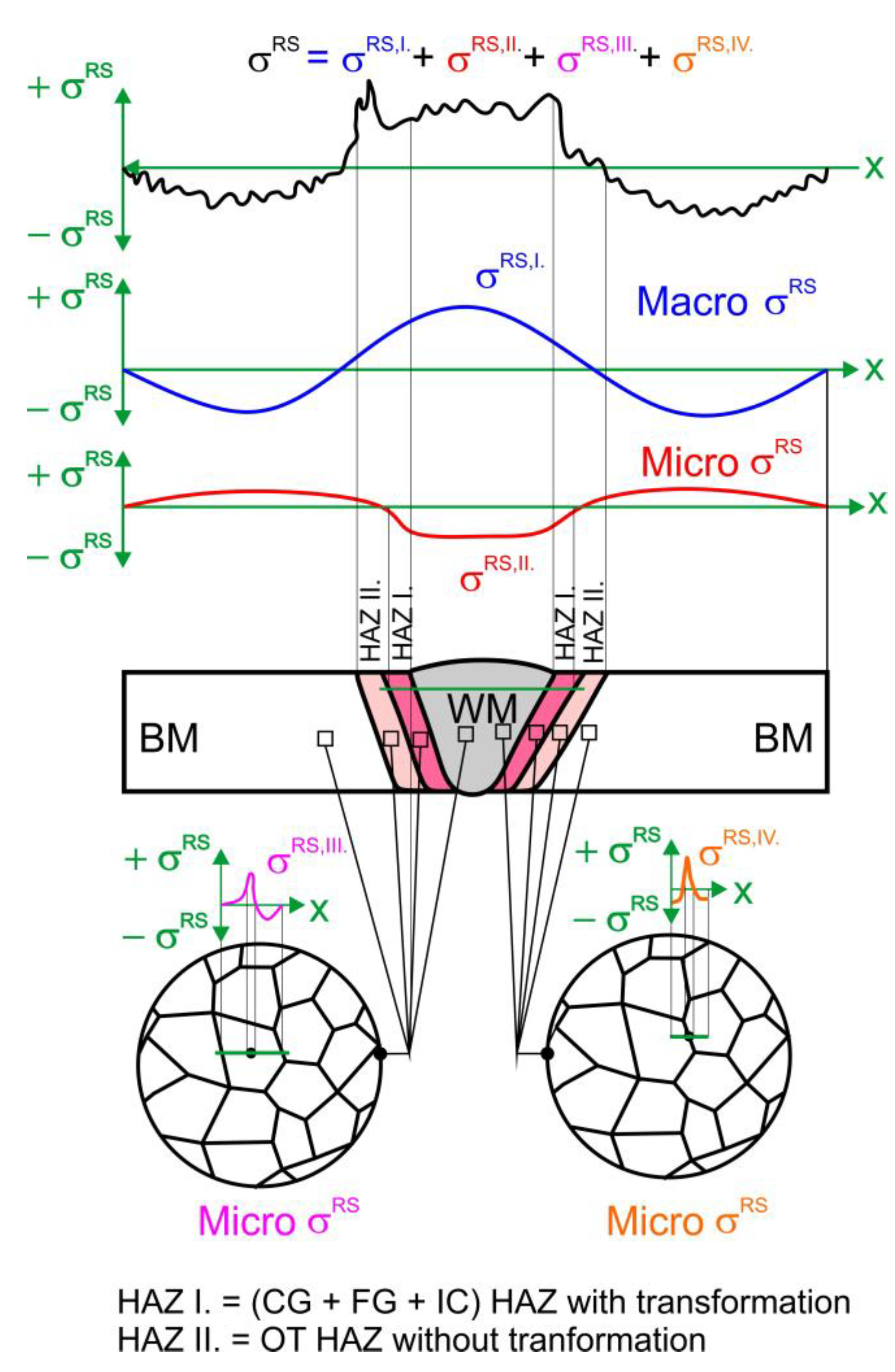
Figure 2.
a) Geometry of the weld groove; b) Sequence of weld passes.
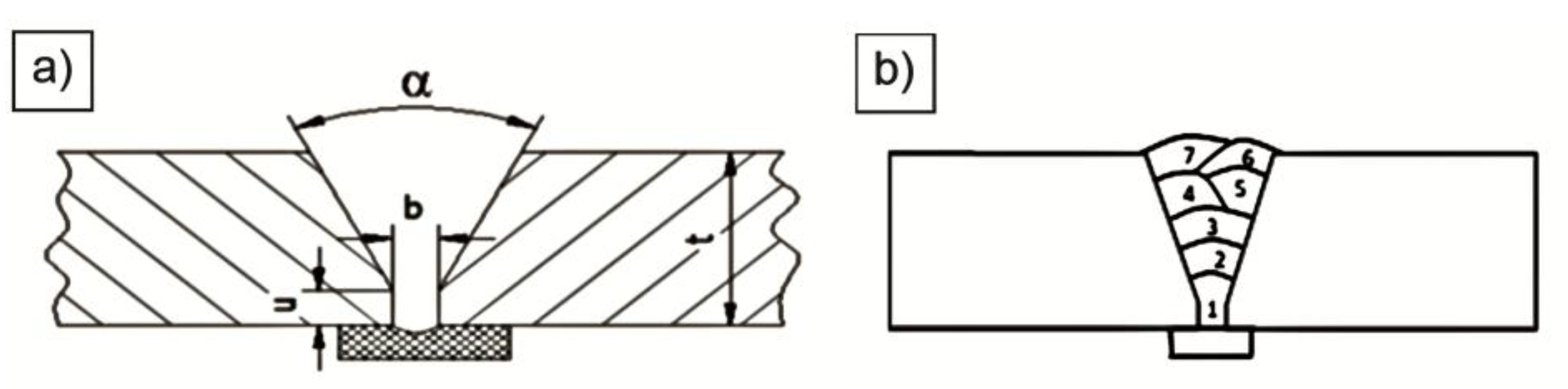
Figure 3.
Geometry of tensile specimens.
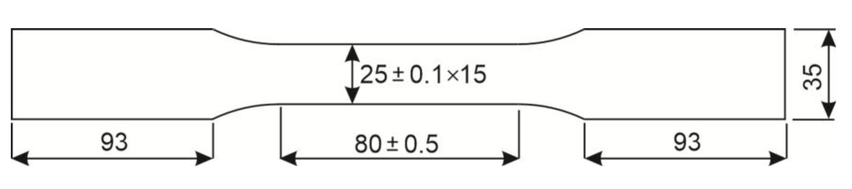
Figure 4.
Coordinates of measuring points (see Table 5).
Figure 4.
Coordinates of measuring points (see Table 5).
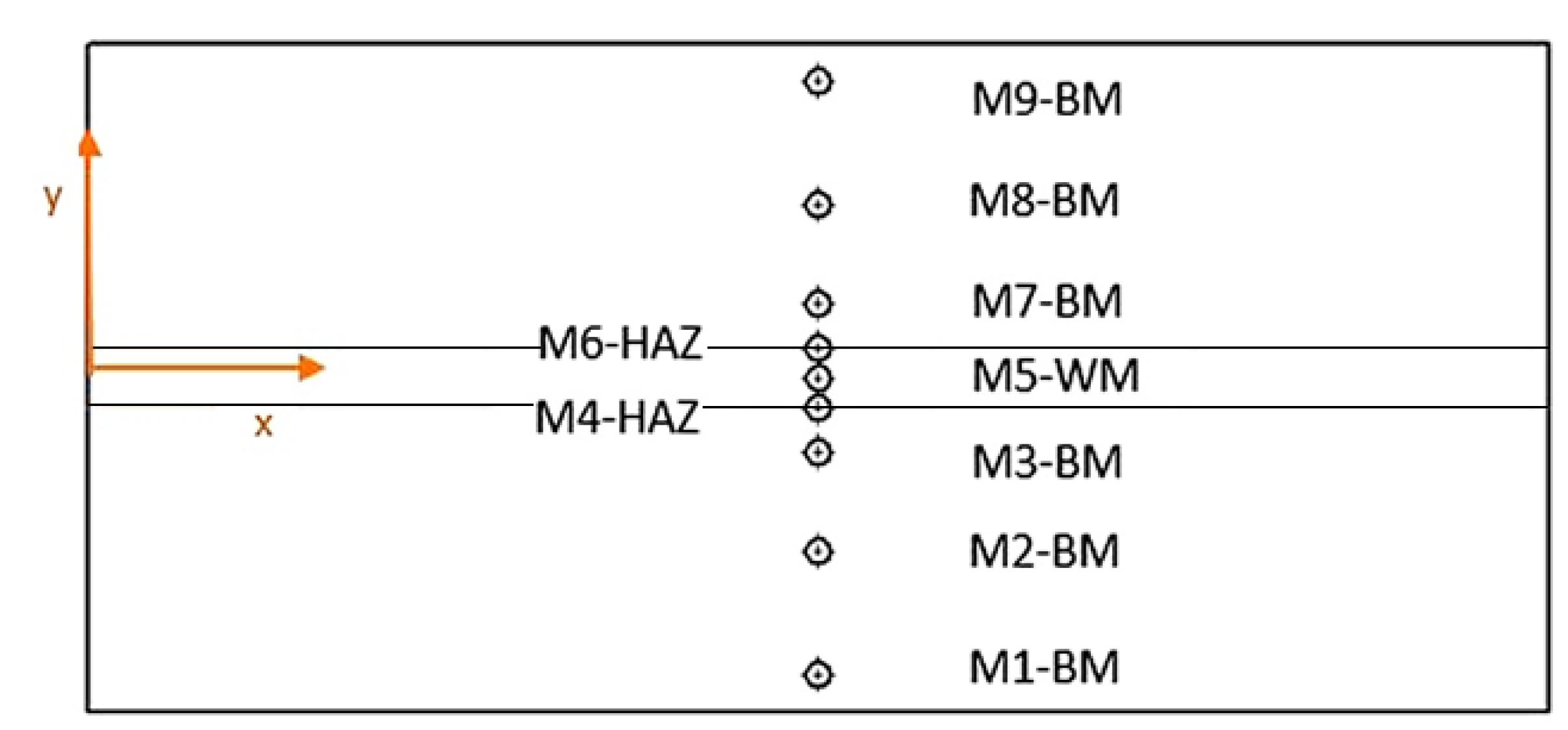
Figure 5.
a) SMMT-1 was used for measurement; b) A tensile test specimen was used for calibration.
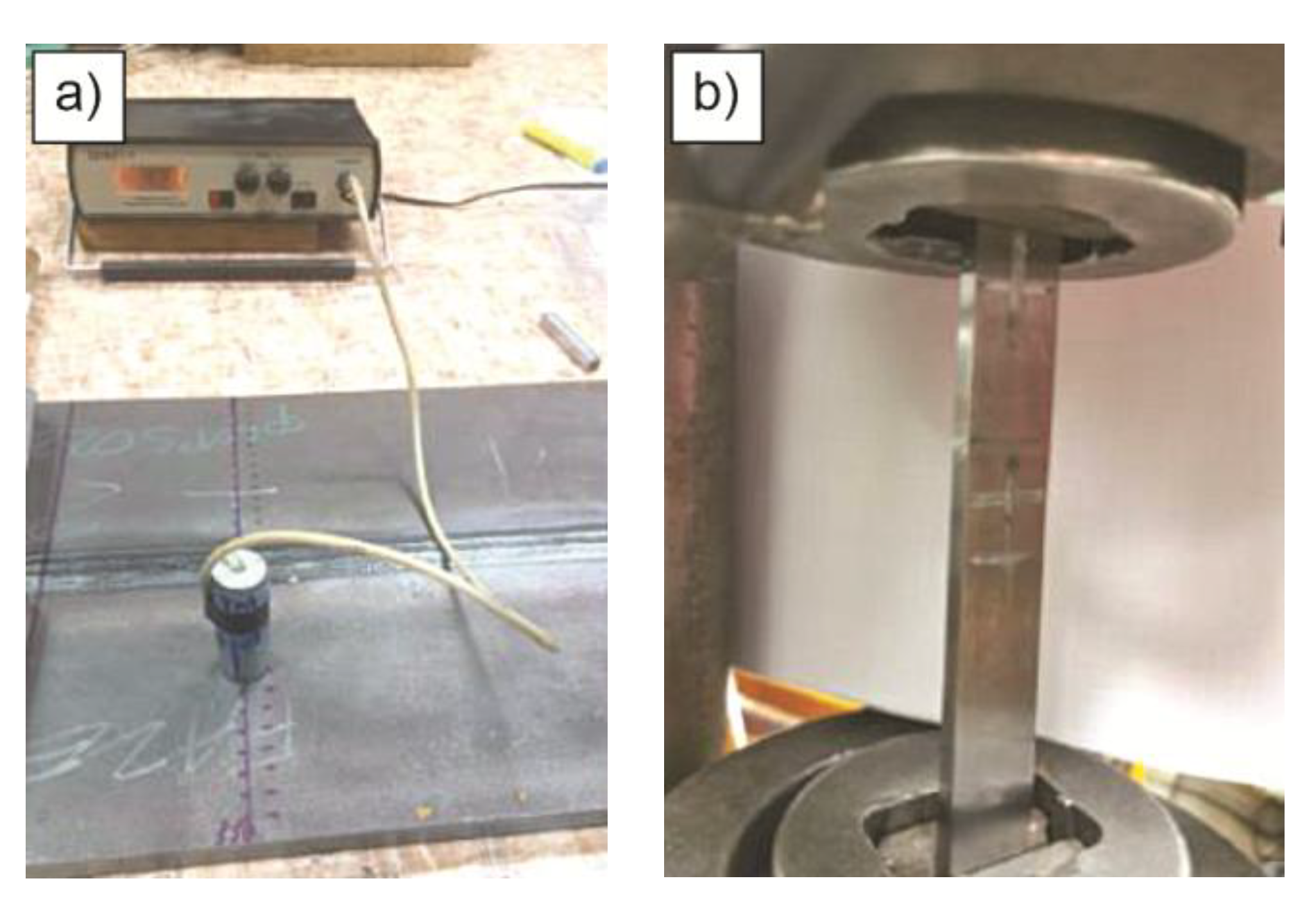
Figure 6.
Calibration curve Stress-Signal voltage.
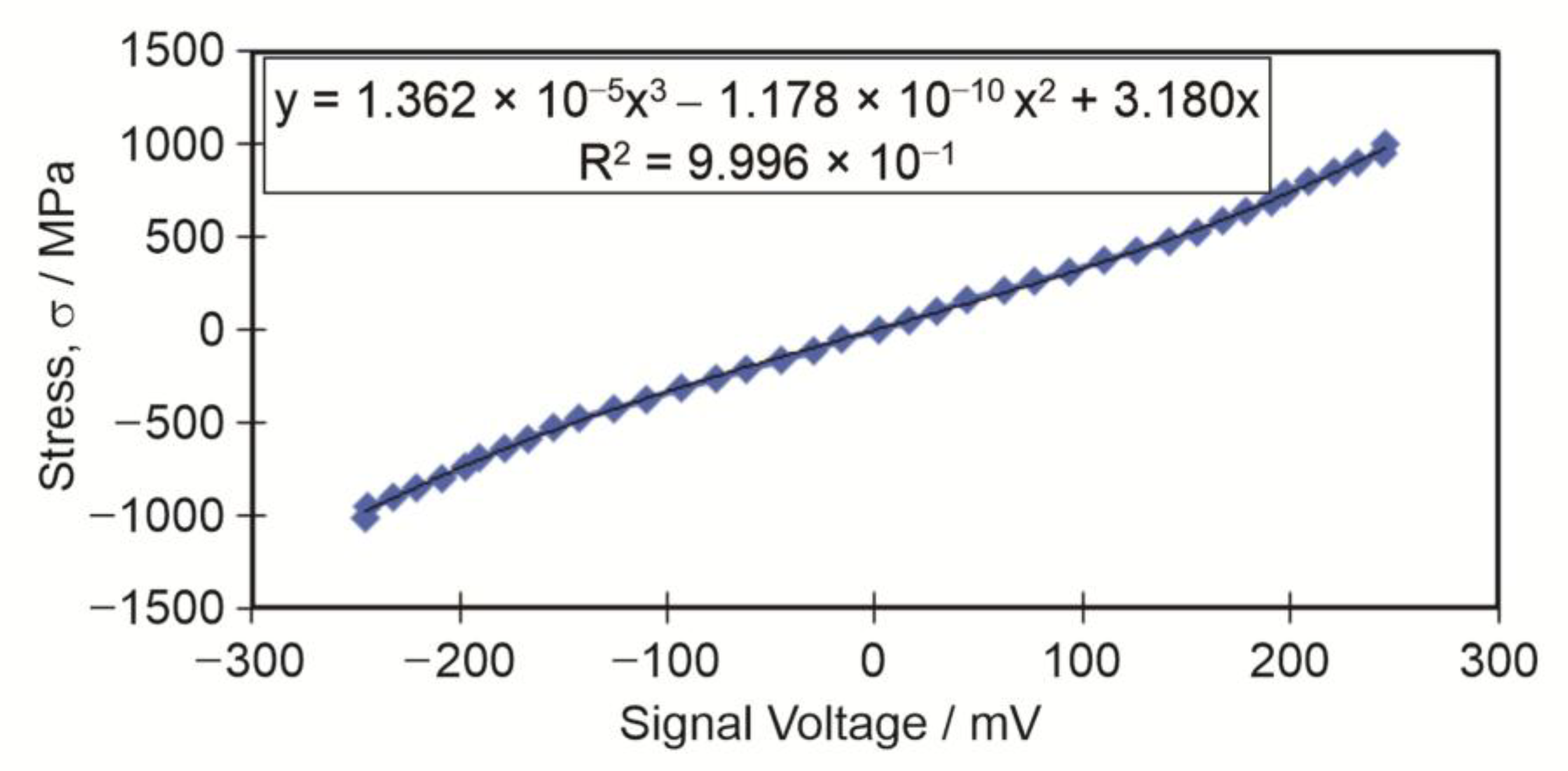
Figure 7.
Measuring device PULSTEC U-X360 for the XRD method.

Figure 8.
The device MTS3000 for centring the drill and drilling a hole at residual stress measurement.
Figure 8.
The device MTS3000 for centring the drill and drilling a hole at residual stress measurement.
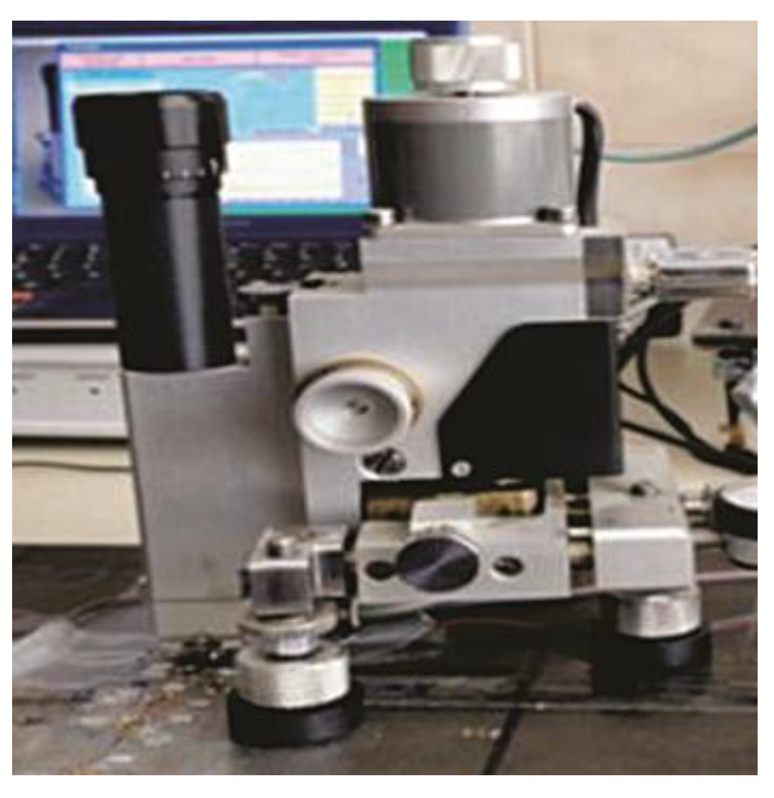
Figure 9.
Microstructures in three areas of the weld join.
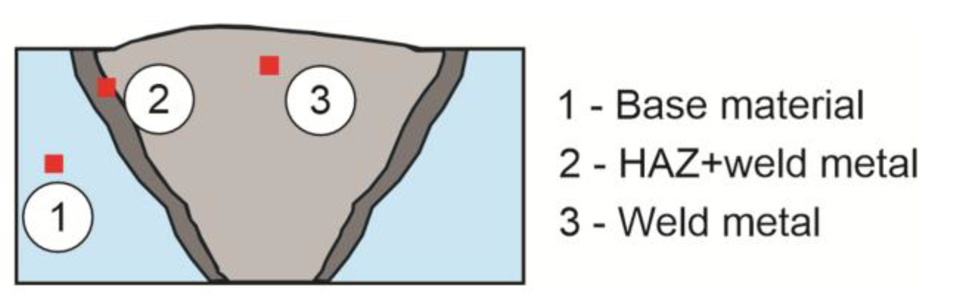
Figure 10.
Subtraction of the principal residual stresses σ1 − σ2, measured by the magnetic method.
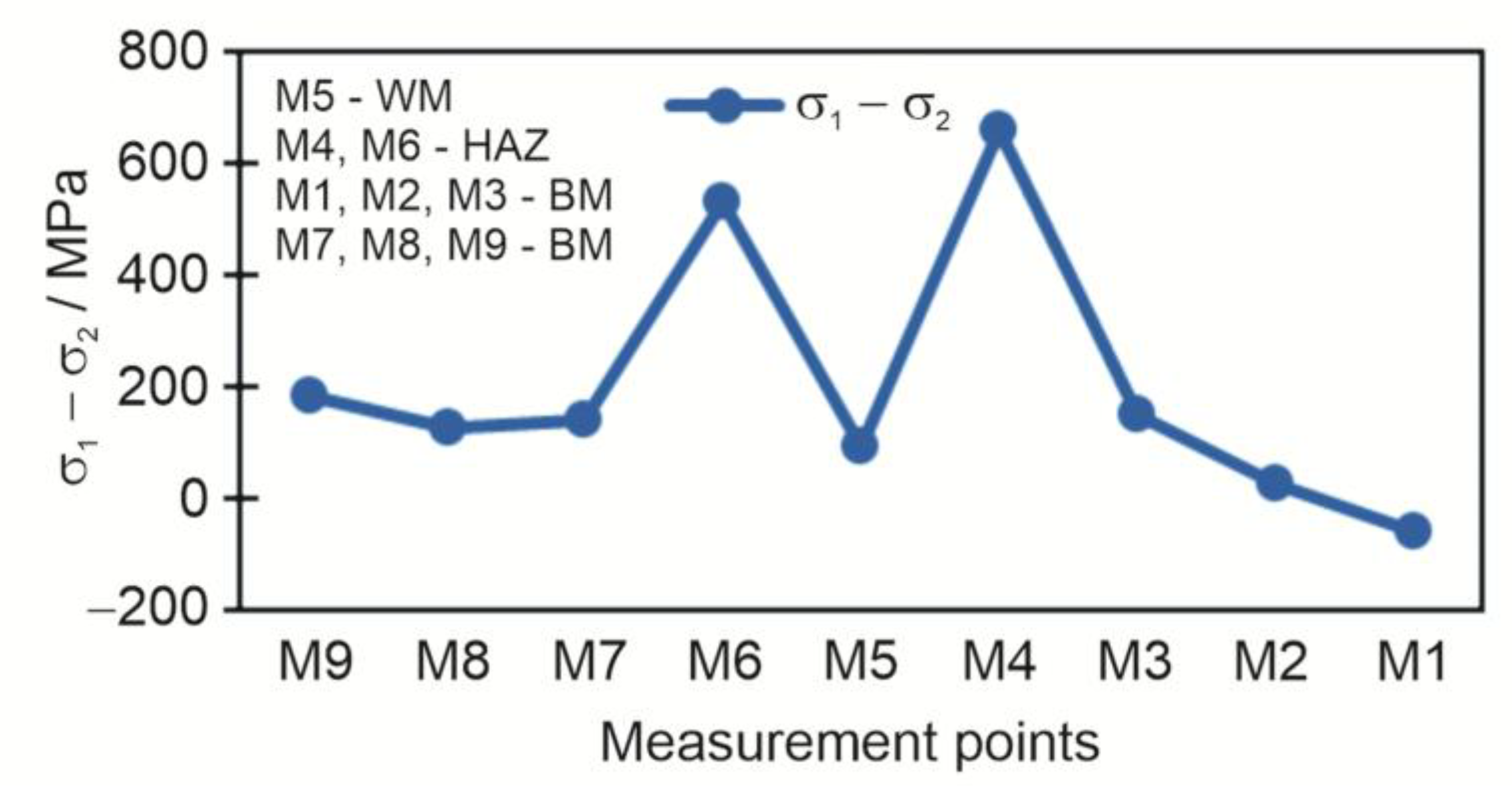
Figure 11.
Residual stresses in the longitudinal and transverse directions measured by the X-ray diffraction method.
Figure 11.
Residual stresses in the longitudinal and transverse directions measured by the X-ray diffraction method.
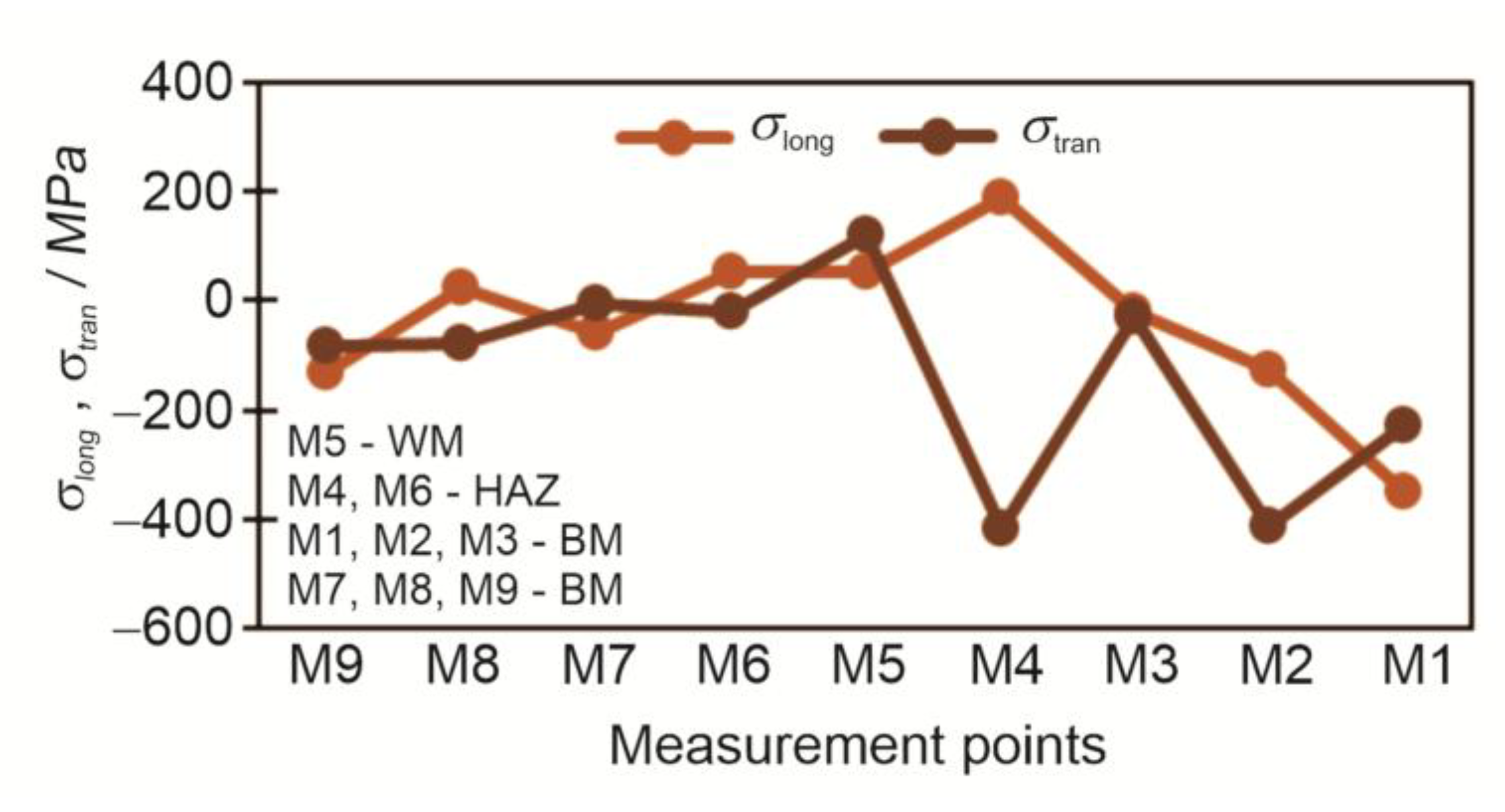
Figure 12.
The Subtraction of longitudinal and transverse residual stresses σlong − σtrans measured by X-ray diffraction.
Figure 12.
The Subtraction of longitudinal and transverse residual stresses σlong − σtrans measured by X-ray diffraction.
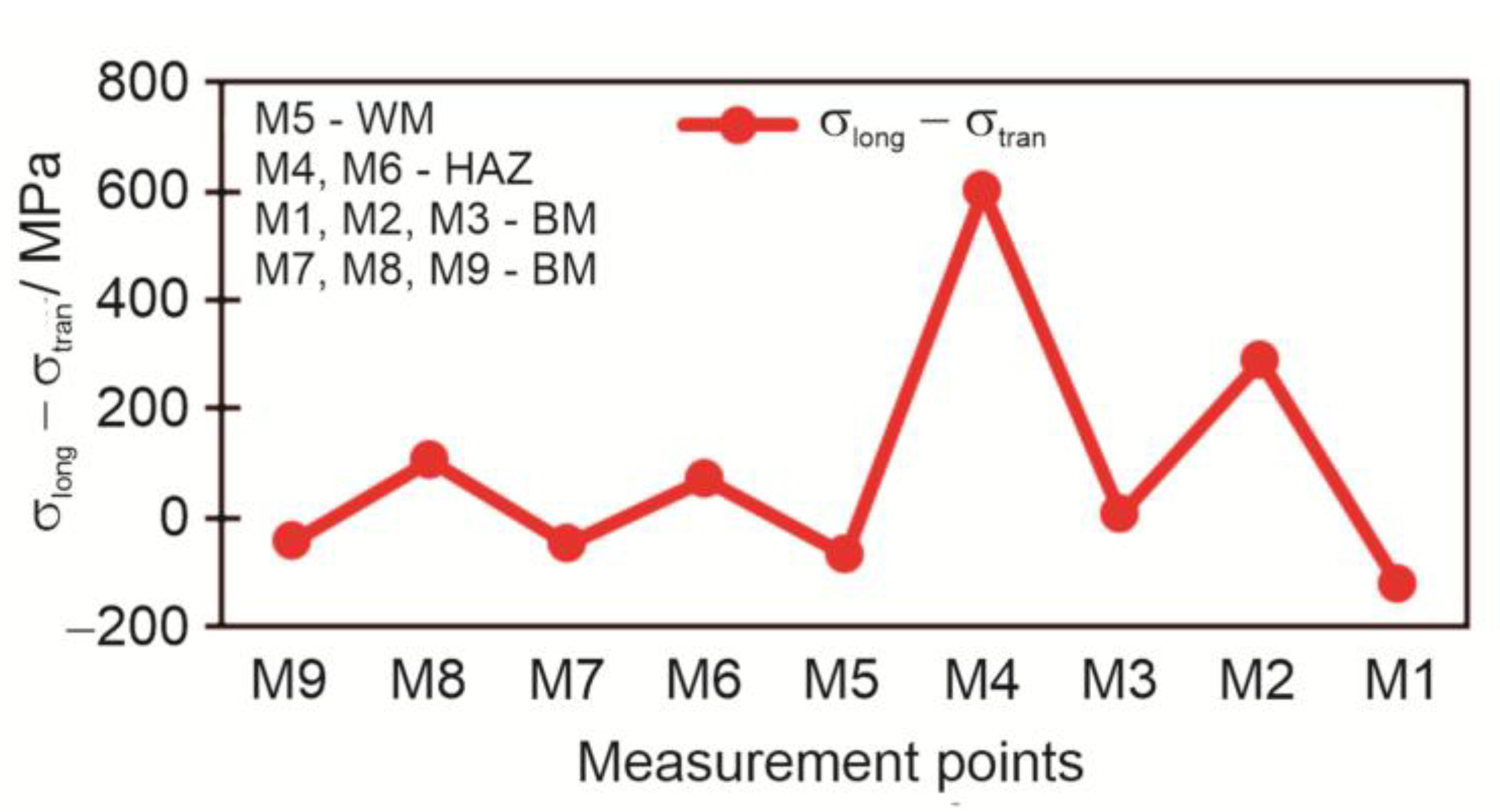
Figure 13.
Measured residual stresses by the hole drilling method for measuring point M1 – base material: a) Measured deformations in individual strain gauges; b) Measured principal stresses and angles; c) Measured longitudinal, transverse and shear stresses.
Figure 13.
Measured residual stresses by the hole drilling method for measuring point M1 – base material: a) Measured deformations in individual strain gauges; b) Measured principal stresses and angles; c) Measured longitudinal, transverse and shear stresses.
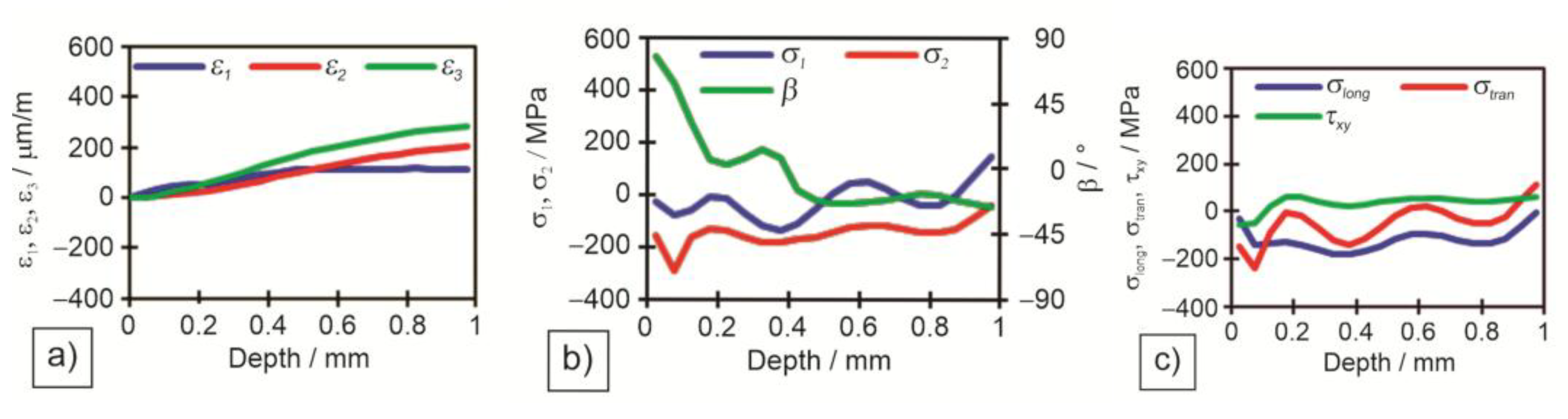
Figure 14.
Measured residual stresses by the hole drilling method for measuring point M4 – heat affected zone: a) Measured deformations in individual strain gauges; b) Measured principal stresses and angles; c) Measured longitudinal, transverse and shear stresses.
Figure 14.
Measured residual stresses by the hole drilling method for measuring point M4 – heat affected zone: a) Measured deformations in individual strain gauges; b) Measured principal stresses and angles; c) Measured longitudinal, transverse and shear stresses.
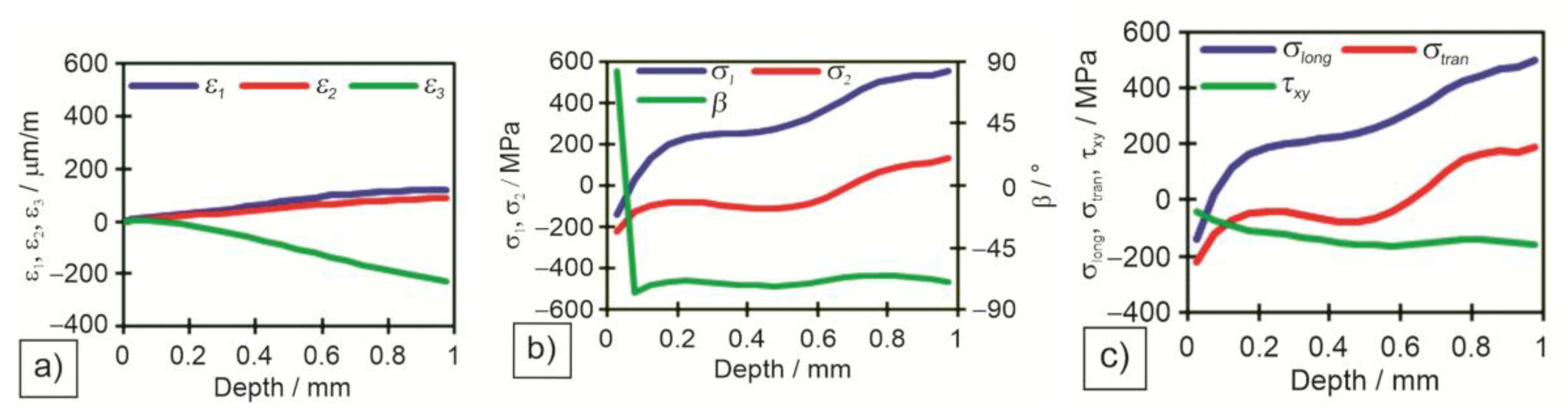
Figure 15.
Measured residual stresses by the hole drilling method for measuring point M5 – weld metal: a) Measured deformations in individual strain gauges; b) Measured principal stresses and angles; c) Measured longitudinal, transverse and shear stresses.
Figure 15.
Measured residual stresses by the hole drilling method for measuring point M5 – weld metal: a) Measured deformations in individual strain gauges; b) Measured principal stresses and angles; c) Measured longitudinal, transverse and shear stresses.

Figure 16.
Subtraction of longitudinal and transverse residual stresses σlong − σtran measured by the hole drilling method at a depth of 1 mm.
Figure 16.
Subtraction of longitudinal and transverse residual stresses σlong − σtran measured by the hole drilling method at a depth of 1 mm.
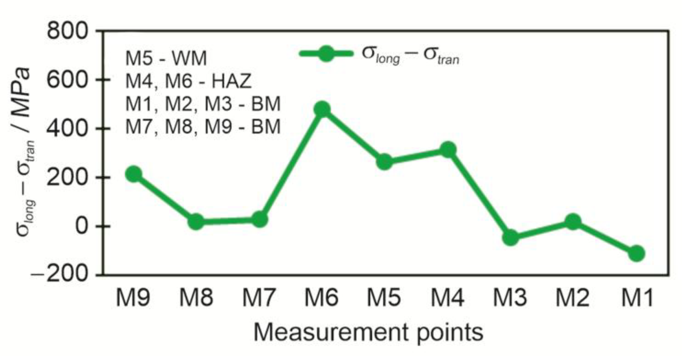
Figure 17.
Microstructure: a) base material; b) HAZ; c) WM – weld metal at weld toe.
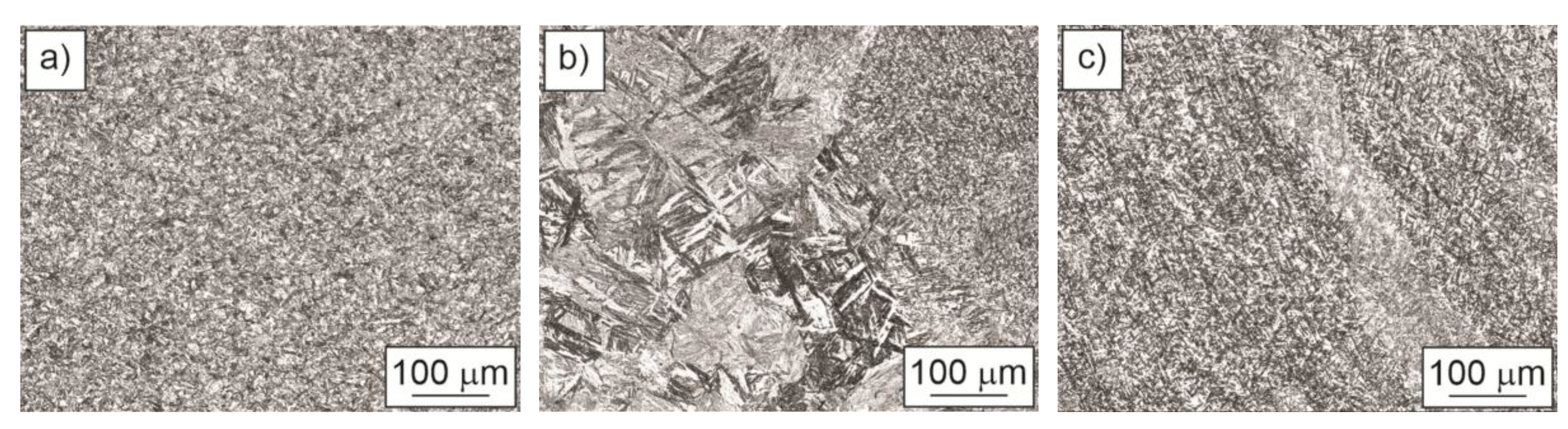
Figure 18.
Comparison of longitudinal residual stresses between HD and XRD methods.
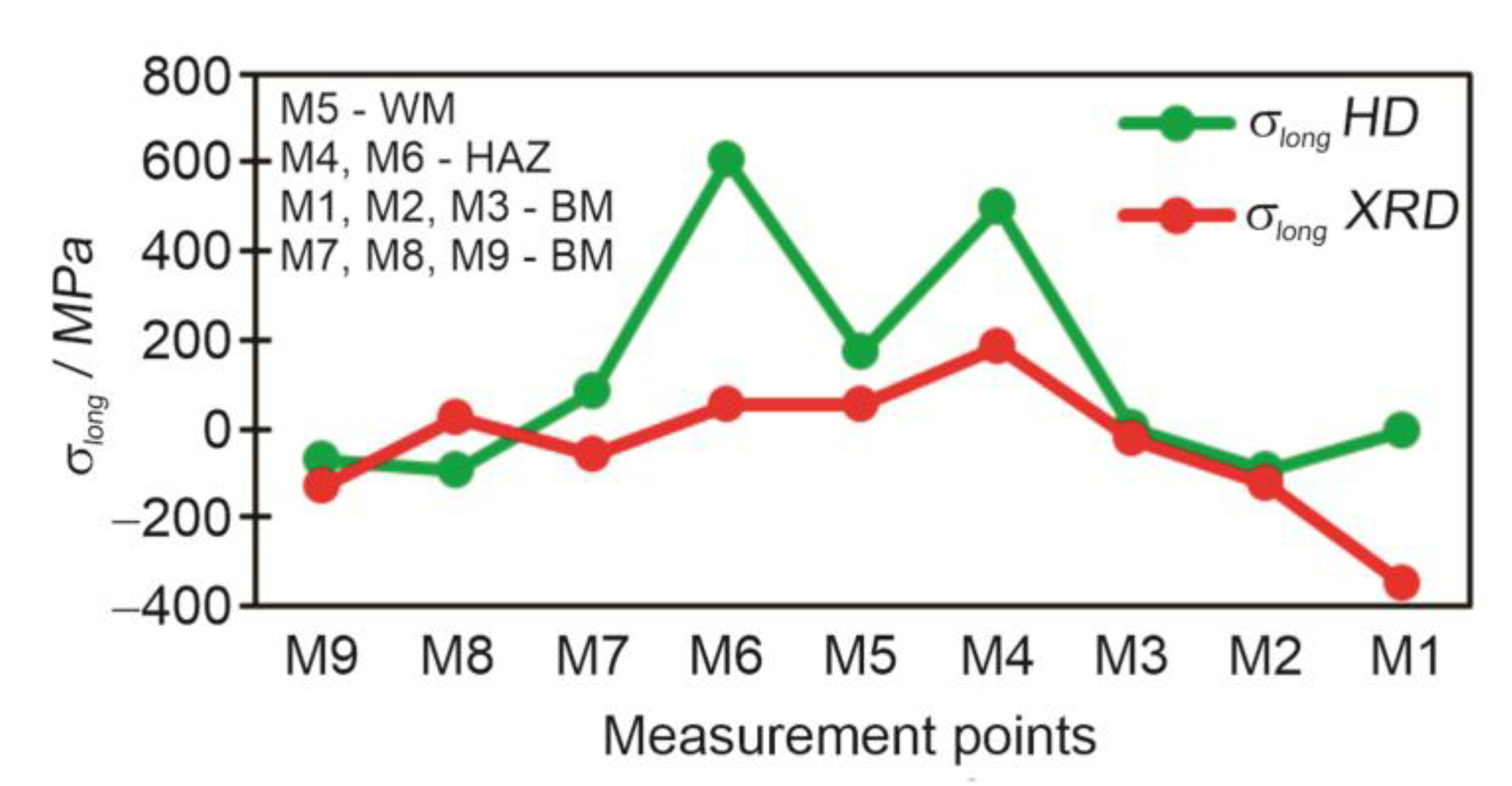
Figure 19.
Comparison of transverse residual stresses between HD and XRD methods.
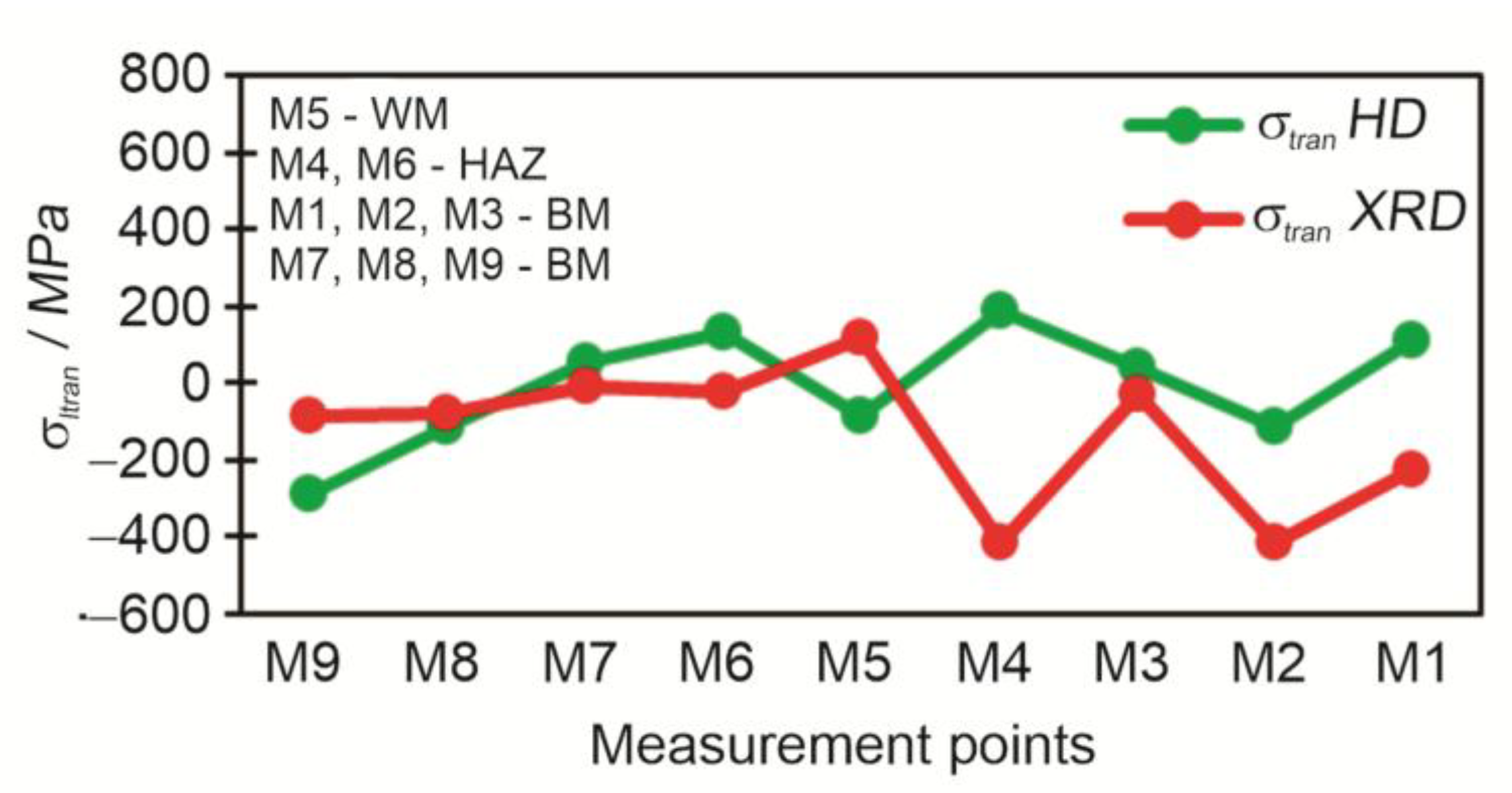
Figure 20.
Comparison of subtractions of longitudinal and transverse residual stresses σlong −σtran between all three measurement methods.
Figure 20.
Comparison of subtractions of longitudinal and transverse residual stresses σlong −σtran between all three measurement methods.
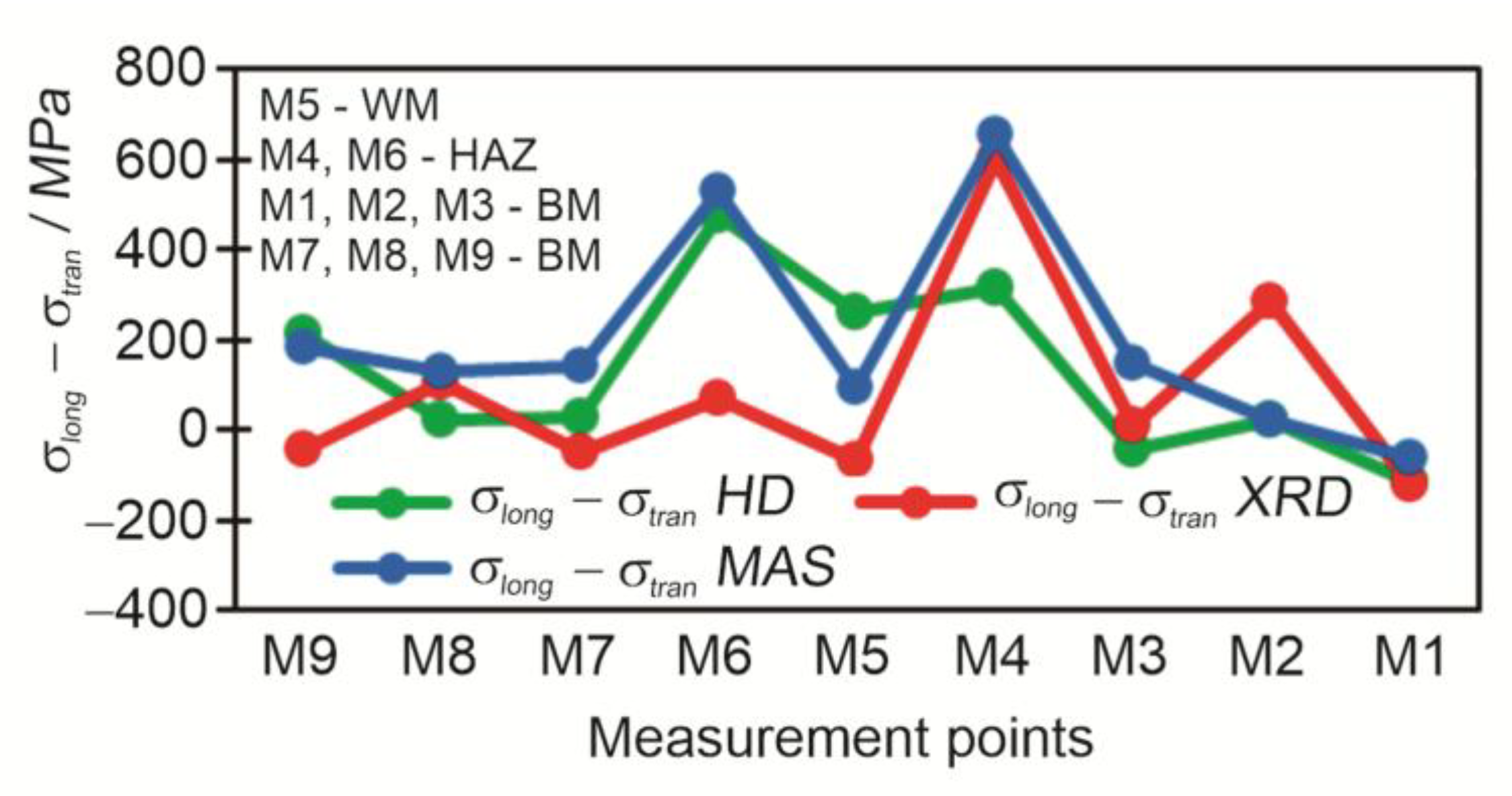

Table 1.
Chemical composition of S960QL steel plate.
| Element – Mass fraction / wt. % | ||||
|---|---|---|---|---|
| C – 0.174 | B – 0.0027 | Cr – 0.623 | N – 0.0015 | Ti – 0.002 |
| Si – 0.297 | P – 0.007 | Cu – 0.043 | Nb – 0.027 | V – 0.002 |
| Mn – 1.070 | S – 0.0017 | Mo – 0.612 | Ni – 0.052 | Zr – 0.001 |
Table 2.
Basic mechanical properties of S960QL steel plate.
| Thickness / mm | Rp0.2 / MPa | Rm / MPa | A / % | KV / J |
|---|---|---|---|---|
| 15.0 | 1014 | 1049 | 13 | 150, 153, 156 (- 40⁰C, long.) |
| 1024 | 1060 | 13 | 45, 43, 49 (- 40⁰C, tran.) |
Table 3.
Chemical composition of filler material.
| Element – Mass fraction / wt. % | ||||||||||||
|---|---|---|---|---|---|---|---|---|---|---|---|---|
| C | Si | Mn | P | S | Cr | Mo | Ni | V | Cu | Ti | Al | Zr |
| 0.09 | 0.78 | 1.79 | 0.008 | 0.008 | 0.36 | 0.70 | 2.15 | <0.01 | 0.04 | 0.06 | <0.01 | <0.01 |
Table 4.
Welding parameters.
| Welding process: MAG – 135 according to EN ISO 4063:23; filler wire diameter φ=1 mm; current DC+ | |||||||
|---|---|---|---|---|---|---|---|
| Run | 1 | 2 | 3 | 4 | 5 | 6 | 7 |
| Welding current / A | 208 | 230 | 240 | 240 | 252 | 258 | 266 |
| Welding Voltage / V | 27.5 | 26.5 | 26.8 | 26.8 | 28 | 29 | 30 |
| Wire Speed / m∙min-1 | 10.7 | 11.5 | 12 | 12 | 14 | 14.3 | 16 |
| Travel Speed / cm∙min-1 | 40 | 38 | 38 | 38 | 35 | 34 | 30 |
| Heat Input / kJ∙cm-1 | 6.8 | 7.6 | 8.1 | 8.1 | 9.6 | 10.5 | 12.7 |
| Shielding gas / l∙min-1 | 15 | 15 | 15 | 15 | 15 | 15 | 15 |
| Preheating / ⁰C | 100 | - | - | - | - | - | - |
| Max. Interpass T / ⁰C | - | 150 | 150 | 150 | 150 | 150 | 150 |
Table 5.
Locations of residual stress measurements.
| Location | X / mm | Y / mm | Area in the weld joint* |
|---|---|---|---|
| M1 | 350 | -120 | BM |
| M2 | 350 | -70 | BM |
| M3 | 350 | -30 | BM |
| M4 | 350 | -14 | HAZ |
| M5 | 350 | 0 | WM |
| M6 | 350 | +14 | HAZ |
| M7 | 350 | +30 | BM |
| M8 | 350 | +70 | BM |
| M9 | 350 | +120 | BM |
*BM=Base Material; HAZ=Heat Affected Zone; WM=Weld Metal.
Table 6.
Results of the tensile test.
| Specimen | Measured tensile strength Rm / N/mm2 |
Reduction of area Z / % |
Tensile strength of the base metal Rmp / N/mm2 |
|---|---|---|---|
| TT-1 | 1025 | 39 | 980-1150* |
| TT-2 | 1038 | 33 | 980-1150* |
* required by EN 10025-6:2019+A1:2023 [45].
Table 7.
Results of magnetic method.
| Measurement point | Signal σ1 – σ2 / mV |
Subtraction of principal stresses σ1 – σ2 / MPa | |
|---|---|---|---|
| M9 | BM | 57.6 | 185 |
| M8 | BM | 39.7 | 127 |
| M7 | BM | 44.0 | 141 |
| M6 | HAZ | 152.1 | 531 |
| M5 | WM | 29.4 | 93 |
| M4 | HAZ | 181.4 | 658 |
| M3 | BM | 46.6 | 149 |
| M2 | BM | 7.9 | 25 |
| M1 | BM | −18.6 | −59 |
Table 8.
Results of residual stresses measured by the X-ray diffraction method.
| Measurement point | Residual stresses in longitudinal direction σlong / MPa |
Residual stresses in transverse direction σtran / MPa |
Subtraction of long. and tran. residual stresses σlong – σtran / MPa |
|
|---|---|---|---|---|
| M9 | BM | −130 | −85 | −45 |
| M8 | BM | 25 | −80 | 105 |
| M7 | BM | −57 | −7 | −50 |
| M6 | HAZ | 52 | −19 | 71 |
| M5 | WM | 53 | 119 | −66 |
| M4 | HAZ | 186 | −415 | 601 |
| M3 | BM | −22 | −31 | 9 |
| M2 | BM | −125 | −413 | 288 |
| M1 | BM | −349 | −228 | −121 |
Table 9.
Results of measurement residual stresses by hole drilling method at a depth of 1 mm.
| Measurement point | Principal stress 1 / MPa 1 / MPa |
Principal stress2 / MPa |
Angle of principal stresses / ° |
Longitudinal stresslong / MPa |
Transverse stresstran / MPa |
Shear stressxy / MPa |
Subtraction of long. and tran. stresseslong − tran / MPa |
|
|---|---|---|---|---|---|---|---|---|
| M1 | BM | −41 | 147 | −26.2 | −4 | 110 | 57 | −114 |
| M2 | BM | −162 | −42 | 49.8 | −92 | −112 | −10 | 20 |
| M3 | BM | −55 | 98 | −36.3 | −1 | 44 | 22 | −45 |
| M4 | HAZ | 136 | 553 | −69.4 | 501 | 188 | −156 | 313 |
| M5 | WM | −90 | 176 | 85.6 | 175 | −88 | −132 | 263 |
| M6 | HAZ | 93 | 644 | −74.8 | 607 | 131 | −238 | 476 |
| M7 | BM | 41 | 97 | 59.5 | 82 | 55 | −13 | 27 |
| M8 | BM | −162 | −42 | 49.8 | −92 | −112 | −10 | 20 |
| M9 | BM | −339 | −19 | 65.9 | −72 | −285 | −106 | 213 |
Disclaimer/Publisher’s Note: The statements, opinions and data contained in all publications are solely those of the individual author(s) and contributor(s) and not of MDPI and/or the editor(s). MDPI and/or the editor(s) disclaim responsibility for any injury to people or property resulting from any ideas, methods, instructions or products referred to in the content. |
© 2025 by the authors. Licensee MDPI, Basel, Switzerland. This article is an open access article distributed under the terms and conditions of the Creative Commons Attribution (CC BY) license (http://creativecommons.org/licenses/by/4.0/).
Copyright: This open access article is published under a Creative Commons CC BY 4.0 license, which permit the free download, distribution, and reuse, provided that the author and preprint are cited in any reuse.


