
Submitted:
29 January 2025
Posted:
30 January 2025
You are already at the latest version
Abstract
The objective of this study is to show the feasibility of producing SiC-aluminum composites by binder jetting 3D printing of SiC preforms and spontaneous infiltration by aluminum. SiC preforms fabricated using binder jetting 3D printing were subjected to several post-processing steps (including curing, depowdering, debinding, and sintering). Sintering was done at 1700°C and infiltration of aluminum was done at 1000°C, with both in a controlled nitrogen environment under a pressure of 25 psi. The bulk density of the sintered SiC preforms was increased by 14% after infiltration. X-ray diffraction and energy-dispersive X-ray spectroscopy confirmed the presence of aluminum in the SiC matrix. This paper is the first to report fabricating SiC-aluminum composites by binder jetting and infiltrating, providing a new approach to producing these composites with potential applications in aerospace and automotive industries
Keywords:
Additive Manufacturing
; Binder Jetting 3D Printing
; Metal Matrix Composite
; Silicon Carbide
1. Introduction
The Metal matrix composites (MMCs) integrate a metallic matrix with another phase, often non-metallic. They are vital in aerospace, automotive, and defense applications due to their high specific strength, stiffness, and wear resistance, as well as their stability at elevated temperatures [1]. The addition of hard ceramic particles such as silicon carbide (SiC) significantly enhances the performance of metal matrices like aluminum [2]. However, conventional MMC fabrication methods, such as stir casting [3] and powder metallurgy [4], face challenges including complex processing, limited geometric flexibility, and uneven reinforcement distribution. Furthermore, it is difficult and costly to machine MMCs into desired shapes [5,6]. The challenges of conventional MMC fabrication methods hinder their widespread industrial adoption. Therefore, it is desirable to develop new methods capable of producing MMC parts with complex geometries at near net-shape [7].
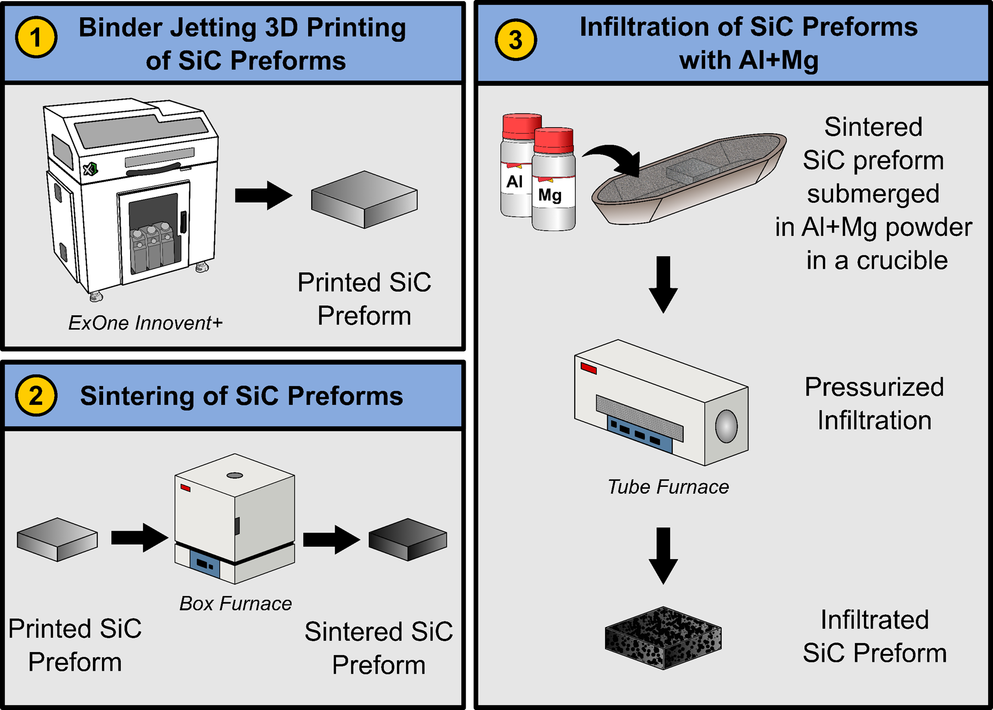
Binder jetting 3D printing enables the layer-by-layer construction of ceramic preforms at room temperature [8]. The printed preforms are sintered to remove the binder and to open up the porosity in the preforms [9]. Afterwards, the preforms undergo metal infiltration to fill the remaining porosity. This approach (separating printing, densification, and infiltration steps) allows for the creation of complex parts.
While there are reported studies on using binder jetting followed by sintering to create metal parts [10], ceramic parts [11], and composite parts [12,13], they often focused on achieving high density using sintering or infiltration [13,14]. Furthermore, there are no reported studies on integrating binder jetting with subsequent metal infiltration to create SiC-aluminum composites. This paper, for the first time, reports an attempt to address this gap using binder jetting to create porous SiC preforms that are then infiltrated with aluminum.
2. Materials and Methods
2.1. Materials
The SiC powder for this study was sourced from Electro Abrasives LLC. (Buffalo, NY, USA). After receiving the powder, the particle size distribution (PSD) was analyzed using a Horiba LA-960 laser scattering particle size distribution analyzer (Kyoto, Japan). The average powder particle size (diameter) was 14 μm. Both the aluminum (Al) powder (Product ID: 1010560250) and magnesium (Mg) powder (Product ID: 13112) were sourced from Sigma-Aldrich in St. Louis, MO, USA.
2.2. Binder Jetting 3d Printing of SiC Preforms
In this study, a silicon carbide (SiC) preform refers to the green part printed using a binder jetting 3D printer (Innovent+, ExOne Company) with aqueous binder (BA005, ExOne Company). SolidWorks 2019, CAD software, was used to create the 3D model of the preform with dimensions of 10 mm (length) × 10 mm (width) × 4 mm (thickness). The same CAD software was also used to generate the STL file of the designed model. The STL file was processed to generate machine-readable instructions that directed the operation of the binder jetting 3D printer.
Figure 1 illustrates the basic steps of binder jetting with powder bed compaction [15]. In Step 1, the build platform is lowered by a distance equal to the sum of layer thickness (LT) and compaction thickness (CT). A heat lamp then moves over the powder bed from left to right to dry the powder. In Step 2, the hopper dispenses powder as it moves across the powder bed from right to left. Simultaneously, a counter-rotating roller spreads the powder in the same direction. In Step 3, the build platform is raised by a distance equal to compaction thickness. The same roller then moves from left to right to compact the powder layer that has the thickness of CT. In Step 4, The print head applies liquid binder to selected regions of the powder bed based on a 3D model. These steps are repeated until the entire part is printed.
The printing parameters and their values used in this study are listed in Table 1. Definitions of these parameters can be found in the literature [16]. These parameter values were chosen after conducting preliminary trials, yielding SiC preforms with no observable defects (more information on the defects will be provided in Section 3).
2.3. Post-Printing Steps (Curing, Depowdering, Debinding, and Sintering) Prior to Infiltration
After printing, the build platform containing the printed SiC preforms was detached from the printer and placed in an oven (DX402C, Yamato Scientific, Tokyo, Japan) at 125 °C for 5 h to cure the binder in the printed preforms [17]. This curing process was essential to provide the printed SiC preforms with sufficient mechanical strength. After curing, the preforms were removed from the build platform, and depowdering was done by gently brushing off any loose powder from their surfaces using a soft brush [9,18].
The debinding and sintering of printed SiC preforms were conducted using a box furnace (KSL-1750X-KA3, MTI). The debinding and sintering cycles for the SiC preforms are shown in Figure 2. Furnace temperature was initially increased from the room temperature (20°C) to 470°C at a rate of 8°C per minute [19]. The temperature was then held at 470°C for 180 minutes to ensure complete binder removal. After debinding, furnace temperature was ramped up to 1700°C at the rate of 8°C per minute. Furnace temperature was maintained at 1700°C for 180 minutes to sinter the preforms. Upon completion of sintering, the furnace was cooled to the room temperature at a rate of ~5°C per minute.
2.4. Infiltration of SiC Preforms with Aluminum
Initially, an Al+Mg mixed powder (at the ratio of 92:8 by weight) was added into a ceramic crucible. A sintered SiC preform was placed inside the crucible and completely buried in the Al+Mg mixed powder. Then the crucible along with the Al+Mg mixed powder and sintered SiC preform was placed inside a tube furnace (Thermo Scientific Lindberg Blue M). The tube furnace was then heated to 1000°C at the rate of 10°C/min and held at 1000°C for 120 minutes under the pressure of 25 psi. During heating, the Mg in the powder enhanced the wettability of Al [20], facilitating Al infiltration into the sintered SiC preform.
2.5. Characterization Techniques
2.5.1. Cross Sectional Imaging of SiC Preform After Infiltration
To prepare the sample for cross sectional imaging, the infiltrated SiC preform was bisected along the Y-Z plane (as shown in Figure 3) where the Z-axis is the print direction (thickness), the X-axis is the powder spread direction, and the Y-axis is perpendicular to the X-Z plane. Cross sectional images of the infiltrated SiC preform were captured using an iPhone 15 Pro Max.
Cross-sectional SEM images of the infiltrated preform were also taken at a magnification of 100x. To prepare the cross-sectional surface for SEM imaging, the cross-sectioned surface of the infiltrated preform was polished using the standard metallurgical method as described in the literature [21], and coated with a 5-nm layer of platinum to enhance conductivity. Field emission scanning electron microscopy (FE-SEM, JSM7500, JEOL, Tokyo, Japan, RRID: SCR_022202) was used to capture microstructural images.
2.5.2. Density Measurement
Green density () of printed SiC preforms was calculated from geometrical and mass measurements. Using a slide caliper (500-196-30 digimatic 0-6’’/150MM stainless steel digital caliper, Mitutoyo, Japan), length, width, and thickness of the printed SiC preforms were measured. A weight scale with a resolution of 0.001 g was used to measure the mass of the printed SiC preforms. Green density of printed SiC preforms was then calculated using Equation (1), where m represents the mass of a printed SiC preform, and l, w, t represent the length, width, and thickness of the printed SiC preform, respectively.
The Archimedes method [22] was used to determine the bulk density of the infiltrated SiC preforms. Using ISO 18754, bulk density can be calculated using Equation (2).
where ρ is the bulk density of the preform, is the density of water, is the dry mass of the preform, is the wet mass of the preform, and is the mass of the preform while submerged in water.
The relative density of the infiltrated preforms was calculated as the ratio of the measured bulk density to the theoretical density of SiC. Theoretical density of SiC is the mass of the atoms in a unit cell divided by the volume of the unit cell. The theoretical density of SiC is 3.21 g/cm3 and was obtained from the literature [23].
2.5.3. Detection of Presence of Aluminum in SiC Preforms Using X-Ray Diffraction
X-ray diffraction analysis of the printed, sintered and infiltrated preforms were performed using a D8 Discover diffractometer manufactured by BRUKER, equipped with a Vantec 500 2D detector. The instrument operated at a power setting of 40 kV and 40 mA, utilizing a copper source with a characteristic wavelength of 1.54056 Å. Data acquisition was conducted over a 2θ range from 5° to 100°. The peaks of the phases were identified using the Inorganic Crystal Structure Database (ICSD) [24].
2.5.4. Composition Analysis Using Energy-Dispersive X-Ray Spectroscopy (EDS)
On the cross-sectional surface of the infiltrated preform polished using the standard metallurgical method as described in the literature [21], composition analysis of infiltrated preform was conducted using an Oxford Energy-Dispersive X-ray Spectroscopy (EDS) system integrated with a JEOL JSM-7500F Field Emission Scanning Electron Microscope (FE-SEM).
3. Results and Discussion
3.1. Cross-Sectional Image of Infiltrated SiC Preform
Figure 4 shows the cross-sectional image of infiltrated preform. It shows that the surface looks darker in the upper region of the cross section of the infiltrated preform, implying that infiltration occurred in this region. This speculation is substantiated by the SEM images of the cross section.
The SEM images in Figure 5 shows the microstructure of infiltrated SiC preform. These SEM images were taken in the upper region and lower region of the cross-sectional surface of the infiltrated preform shown in Figure 4. The SEM image taken in the upper region, shown in Figure 5(a), has mostly filled pores with only a few remaining voids, confirming successful aluminum infiltration. The SEM image taken in the lower region, shown in Figure 5(b), contains large, irregularly shaped pores, suggesting incomplete aluminum infiltration.
The incomplete infiltration is likely due to the high compaction during printing, which created a dense green preform, and the high sintering temperature of 1700°C, which increased the bulk density of the sintered preform. These factors restricted the flow of the Al+Mg mixed powder through the entire SiC matrix.
3.1. Density
Figure 6 shows the bulk density and relative density of printed SiC preform, sintered SiC preform and infiltrated SiC preform. The green density (about 1.8 g/cm3) and relative density (56.07%) of the printed preform were lower than those of the sintered preform and the infiltrated preform. This is due to the high porosity and the presence of binder materials. After debinding, the bulk density increases to about 2.07 g/cm3, with a relative density of 62.31%. This increase happens because the binder is removed, and the sintering process partially densifies the SiC preform by reducing open porosity. Following aluminum infiltration at 1000°C, the bulk density rises further to approximately 2.36 g/cm3, with a relative density of 73.44%.
3.1. Composition
Figure 7 shows X-ray diffraction (XRD) patterns of printed preform, sintered preform, and infiltrated preform. The printed preform displays peaks corresponding solely to SiC, indicating the presence of the base material with no additional phases. After sintering, the XRD pattern remains dominated by SiC peaks, suggesting that sintering does not introduce any significant phase changes. After aluminum infiltration, additional peaks associated with aluminum and magnesium appear prominently in the XRD pattern. The aluminum peaks were particularly evident at 2θ values of around 38.19° and 44.82°. A peak observed at 2θ value of 38.19° aligns closely with the reference peak for Al2O3 (at 2θ value of 37.80° [24]). Peaks at 2θ values of 31.34°, 42.89°, and 56.21° confirm the presence of Al4C3. Peaks observed at 2θ values of 36.8° and 47.44° confirm the presence of Mg while peaks at 36.8° and 42.89° confirm the presence of MgO. For easy observations, dotted vertical lines are added at 2θ values of 31.34°, 36.8°, 42.89°, 47.44°, and 56.21°.
Figure 8 shows the elemental mapping of the infiltrated SiC preform in the upper region of the cross section shown in Figure 5. The mapping highlights the distribution of key elements: carbon (C), oxygen (O), magnesium (Mg), aluminum (Al), and silicon (Si). Aluminum is present in the upper region of the infiltrated preform. Carbon and silicon are prominently distributed, representing the SiC matrix. Oxygen is observed in small amounts, likely due to minor surface oxidation during processing. Magnesium is also detected. The elemental mapping demonstrates successful aluminum penetration in the upper region of the sintered SiC preform.
4. Conclusions
This study demonstrates the feasibility of fabricating SiC-aluminum composites through binder jetting 3D printing and subsequent aluminum infiltration. The bulk density of the printed preform is increased by 15% after sintering, increased by 31% after infiltration. Visual inspection of cross-section surface revealed that infiltration was localized to the upper region of the cross-section of the infiltrated preform. SEM images revealed that the upper region predominantly contained filled pores with only a few remaining voids, while the lower region exhibited large, irregularly shaped pores, indicating incomplete aluminum infiltration. Characterization using X-ray diffraction (XRD) and Energy Dispersive X-ray Spectroscopy (EDS) confirmed the successful incorporation of aluminum into the SiC matrix.
Future research will focus on effects of key parameters, such as SiC powder characteristics (e.g., particle size and distribution), layer thickness and compaction thickness in binder jetting, sintering temperature and dwell time, and infiltration pressure and temperature.
Author Contributions
Conceptualization, F.K. and Z.P.; methodology, F.K., M.S.A.; software, F.K.; validation, F.K., M.S.A., J.S. and Z.P.; formal analysis, F.K., M.S.A.; investigation, F.K., M.S.A., J.S. and M.M.P.;; resources, F.K., Z.P., and S.K.; data curation, F.K. and Z.P.; writing—original draft preparation, F.K., J.S.; writing—review and editing, F.K., J.S., M.S.A., M.M.P., Z.P., S.K.; visualization, F.K.; supervision, Z.P. All authors have read and agreed to the published version of the manuscript.
Funding
This research received no external funding
Data Availability Statement
Data are available upon reasonable request made to the authors.
Conflicts of Interest
The authors declare no conflicts of interest
References
- Chen, L.-Y.; Qin, P.; Zhang, L.; Zhang, L.-C. An overview of additively manufactured metal matrix composites: preparation, performance, and challenge. International Journal of Extreme Manufacturing 2024. [Google Scholar] [CrossRef]
- Ghinatti, E.; Bertolini, R.; Sorgato, M.; Ghiotti, A.; Bruschi, S. Tool wear and surface finish analysis after drilling Al-SiC metal matrix composite with DLC-coated tools at varying feed. Procedia CIRP 2024, 123, 53–58. [Google Scholar] [CrossRef]
- Kumar, J.; Singh, D.; Kalsi, N.S.; Sharma, S.; Mia, M.; Singh, J.; Rahman, M.A.; Khan, A.M.; Rao, K.V. Investigation on the mechanical, tribological, morphological and machinability behavior of stir-casted Al/SiC/Mo reinforced MMCs. Journal of Materials Research and Technology 2021, 12, 930–946. [Google Scholar] [CrossRef]
- Wang, H.; Zhang, R.; Hu, X.; Wang, C.-A.; Huang, Y. Characterization of a powder metallurgy SiC/Cu–Al composite. Journal of materials processing technology 2008, 197, 43–48. [Google Scholar] [CrossRef]
- Sadhu, K.K.; Mandal, N.; Sahoo, R.R. SiC/graphene reinforced aluminum metal matrix composites prepared by powder metallurgy: A review. Journal of Manufacturing Processes 2023, 91, 10–43. [Google Scholar] [CrossRef]
- GHINATTI, E. Ultrasonic vibration assisted turning for reducing tool wear in metal matrix composite machining.
- Liu, J.; Zheng, Z.; Wang, J.; Wu, Y.; Tang, W.; Lü, J. Pressureless infiltration of liquid aluminum alloy into SiC preforms to form near-net-shape SiC/Al composites. Journal of Alloys and Compounds 2008, 465, 239–243. [Google Scholar] [CrossRef]
- Polozov, I.; Razumov, N.; Masaylo, D.; Silin, A.; Lebedeva, Y.; Popovich, A. Fabrication of silicon carbide fiber-reinforced silicon carbide matrix composites using binder jetting additive manufacturing from irregularly-shaped and spherical powders. Materials 2020, 13, 1766. [Google Scholar] [CrossRef] [PubMed]
- Wang, Y.; Zhao, Y.F. Investigation of sintering shrinkage in binder jetting additive manufacturing process. Procedia Manufacturing 2017, 10, 779–790. [Google Scholar] [CrossRef]
- Bai, Y.; Wagner, G.; Williams, C.B. Effect of particle size distribution on powder packing and sintering in binder jetting additive manufacturing of metals. Journal of Manufacturing Science and Engineering 2017, 139, 081019. [Google Scholar] [CrossRef]
- Du, W.; Ren, X.; Ma, C.; Pei, Z. Binder jetting additive manufacturing of ceramics: A literature review. In ASME international mechanical engineering congress and exposition; American Society of Mechanical Engineers, 2017. [Google Scholar]
- Do, T.; Kwon, P.; Shin, C.S. Process development toward full-density stainless steel parts with binder jetting printing. International Journal of Machine Tools and Manufacture 2017, 121, 50–60. [Google Scholar] [CrossRef]
- Du, W.; Ren, X.; Pei, Z.; Ma, C. Ceramic binder jetting additive manufacturing: a literature review on density. Journal of Manufacturing Science and Engineering 2020, 142, 040801. [Google Scholar] [CrossRef]
- Zulfia, A.; Hand, R. The production of Al-Mg alloy/SiC metal matrix composites by pressureless infiltration. Journal of Materials Science 2002, 37, 955–961. [Google Scholar] [CrossRef]
- Pasha, M.M.; Arman, M.S.; Khan, F.; Pei, Z.; Kachur, S. Effects of Layer Thickness and Compaction Thickness on Green Part Density in Binder Jetting Additive Manufacturing of Silicon Carbide: Designed Experiments. Journal of Manufacturing and Materials Processing 2024, 8, 148. [Google Scholar] [CrossRef]
- Mostafaei, A.; Elliott, A.M.; Barnes, J.E.; Li, F.; Tan, W.; Cramer, C.L.; Nandwana, P.; Chmielus, M. Binder jet 3D printing—Process parameters, materials, properties; modeling, and challenges. Progress in Materials Science 2021, 119, 100707. [Google Scholar] [CrossRef]
- Moghadasi, M.; Du, W.; Li, M.; Pei, Z.; Ma, C. , Ceramic binder jetting additive manufacturing: Effects of particle size on feedstock powder and final part properties. Ceramics International 2020, 46, 16966–16972. [Google Scholar] [CrossRef]
- Khan, F.; Arman, M.S.; Sanders, J.; Pasha, M.M.; Rahman, A.M.; Pei, Z.; Dong, T. Binder Jetting 3D Printing Utilizing Waste Algae Powder: A Feasibility Study. Intelligent and Sustainable Manufacturing 2024, 1, 10016. [Google Scholar] [CrossRef]
- Porter, Q.; Moghadasi, M.; Pei, Z.; Ma, C. Dense and strong ceramic composites via binder jetting and spontaneous infiltration. Ceramics International 2023, 49, 17363–17370. [Google Scholar] [CrossRef]
- Aguilar-Martinez, J.; Hernandez, M.; Castillo-Torres, J.; Pech-Canul, M. Effect of particle size and Mg content on the processing parameters of Al-Si-Mg/SiCp composites processed by pressureless infiltration. Revista mexicana de física 2007, 53, 198–204. [Google Scholar]
- Täffner, U.; Carle, V.; Schäfer, U.; Hoffmann, M.J. Preparation and microstructural analysis of high-performance ceramics, in Metallography and microstructures; ASM International, 2004; pp. 1057–1066. [Google Scholar]
- ISO 18754,2020; Fine ceramics (Advanced Ceramics, Advanced Technical Ceramics)-Determination of Density and Apparent Porosity. International Organization for Standardization, 2013.
- Vaßen, R.; Kaiser, A.; Förster, J.; Buchkremer, H.; Stöver, D. , Densification of ultrafine SiC powders. Journal of materials science 1996, 31, 3623–3637. [Google Scholar] [CrossRef]
- Inorganic Crystal Structure Database. 1913. Available online: https://icsd.products.fiz-karlsruhe.de/en/about/about-icsd (accessed on 24 January 2025).
Figure 1.
Four steps in binder jetting using powder bed compaction (layer thickness is represented by LT, and compaction thickness is represented by CT) [15].
Figure 1.
Four steps in binder jetting using powder bed compaction (layer thickness is represented by LT, and compaction thickness is represented by CT) [15].
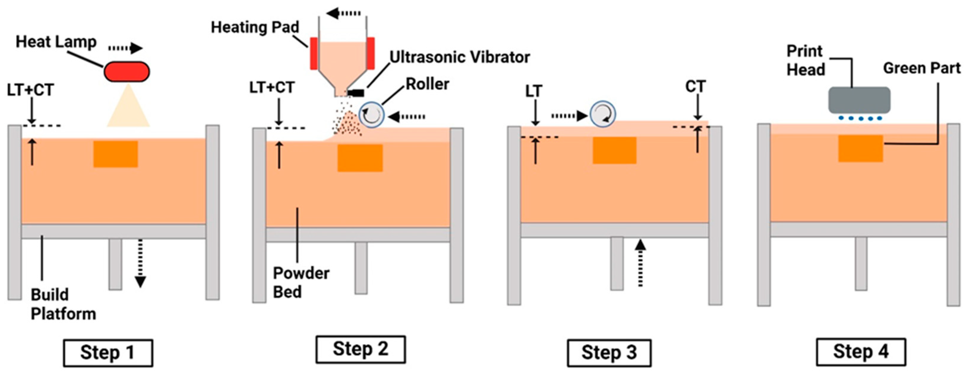
Figure 2.
Debinding and sintering cycle of the box furnace for SiC preforms.
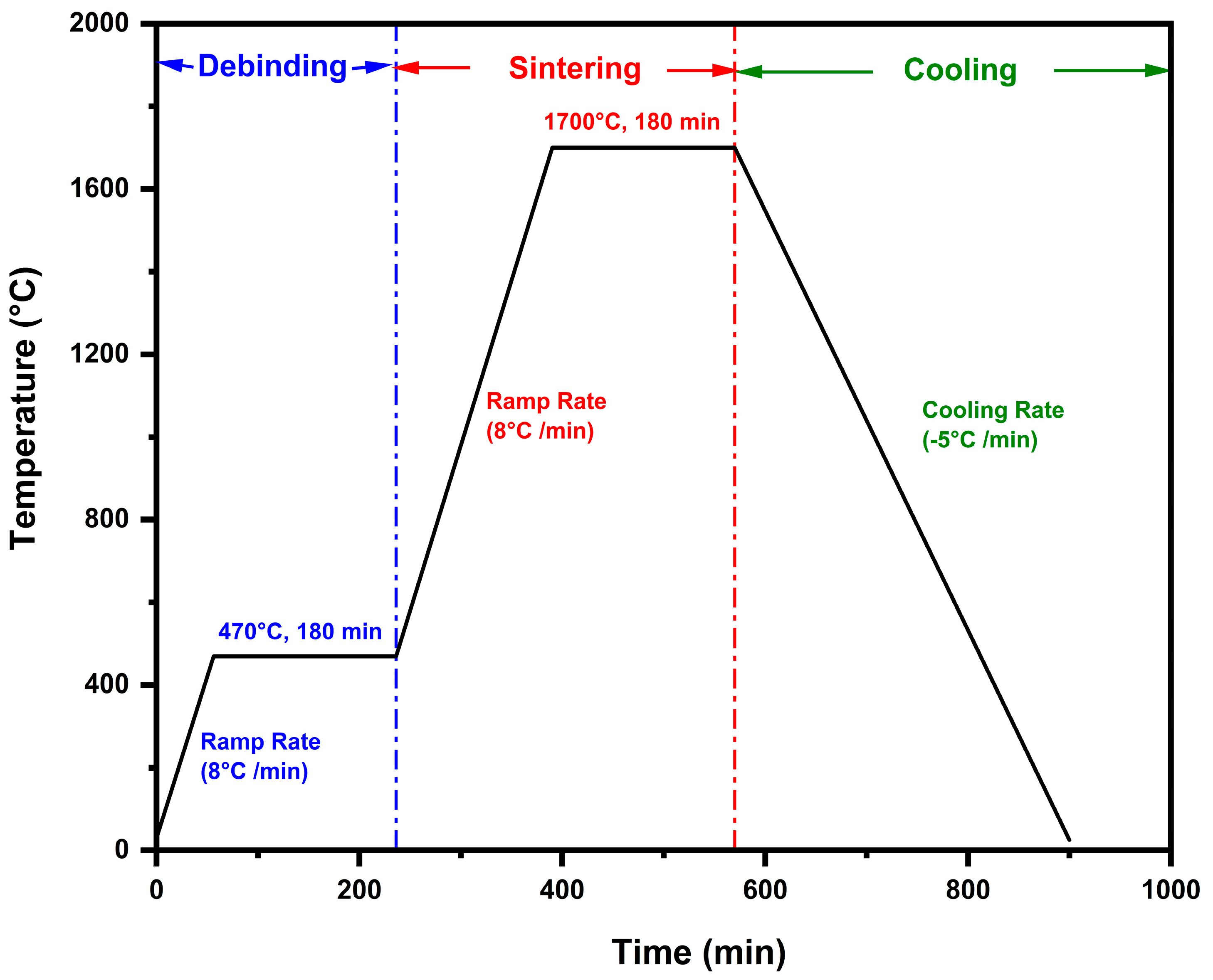
Figure 3.
Bisecting plane parallel to the Y-Z plane of the printed preform.
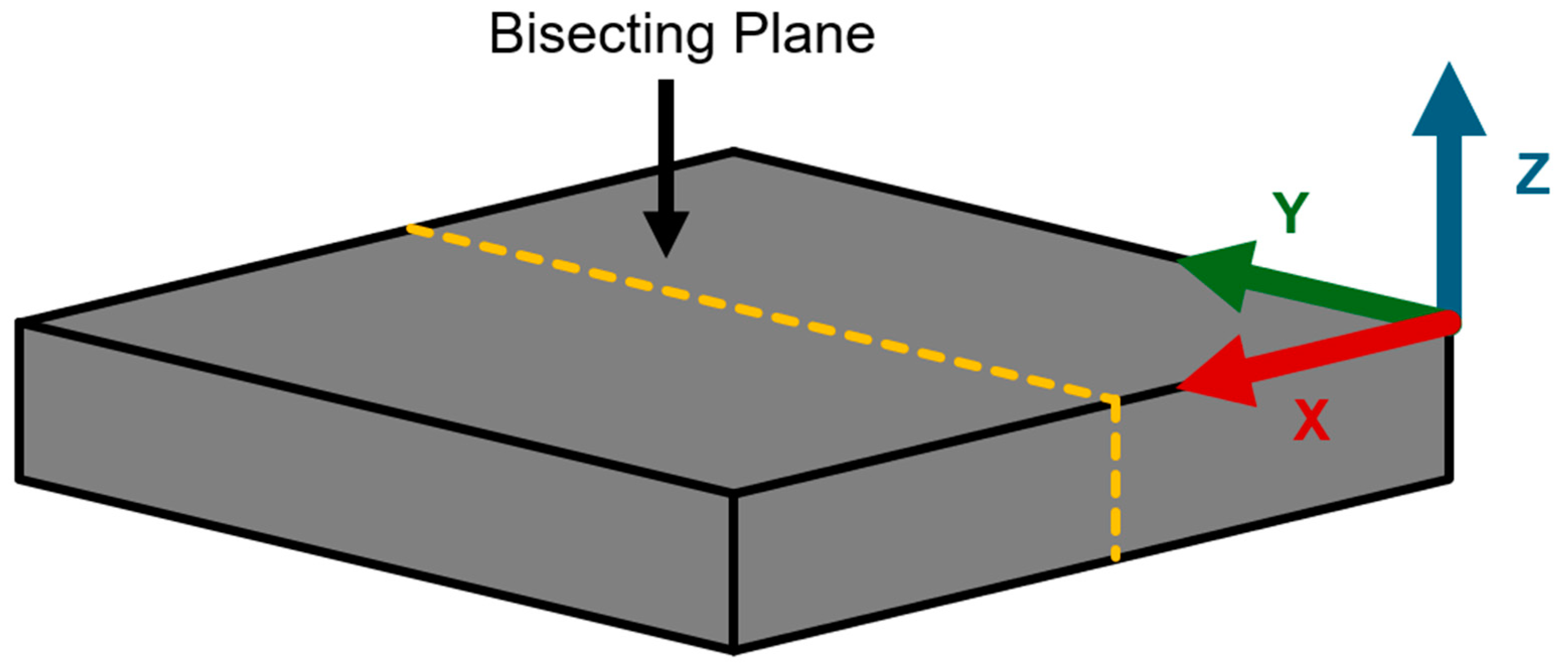
Figure 4.
Cross-sectional image of infiltrated SiC preform.
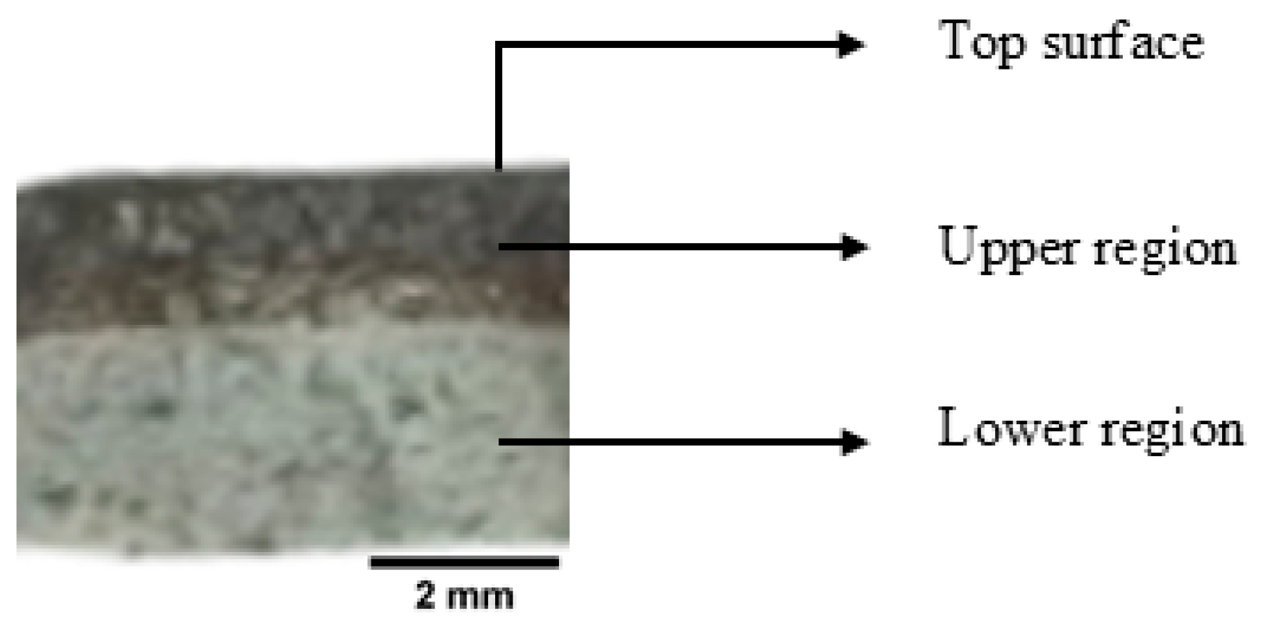
Figure 5.
SEM images of cross-sectional surface of the infiltrated preform in (a) the upper region, and (b) the lower region.
Figure 5.
SEM images of cross-sectional surface of the infiltrated preform in (a) the upper region, and (b) the lower region.
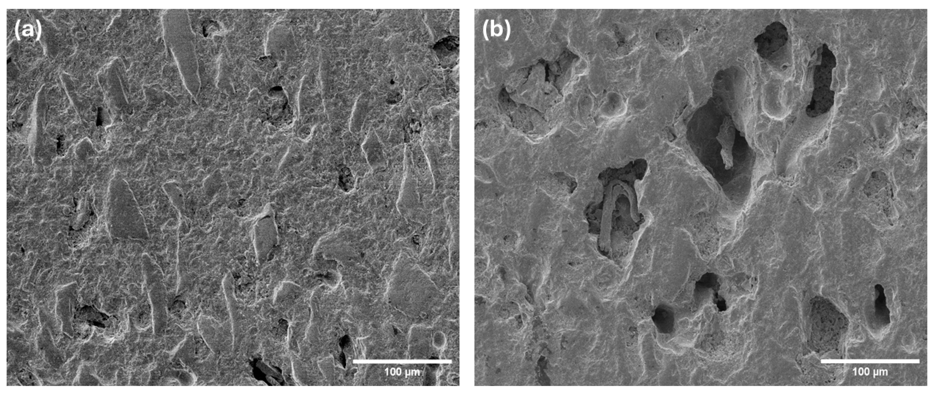
Figure 6.
Bulk density and relative density of the printed preform, sintered preform, and infiltrated preform.
Figure 6.
Bulk density and relative density of the printed preform, sintered preform, and infiltrated preform.
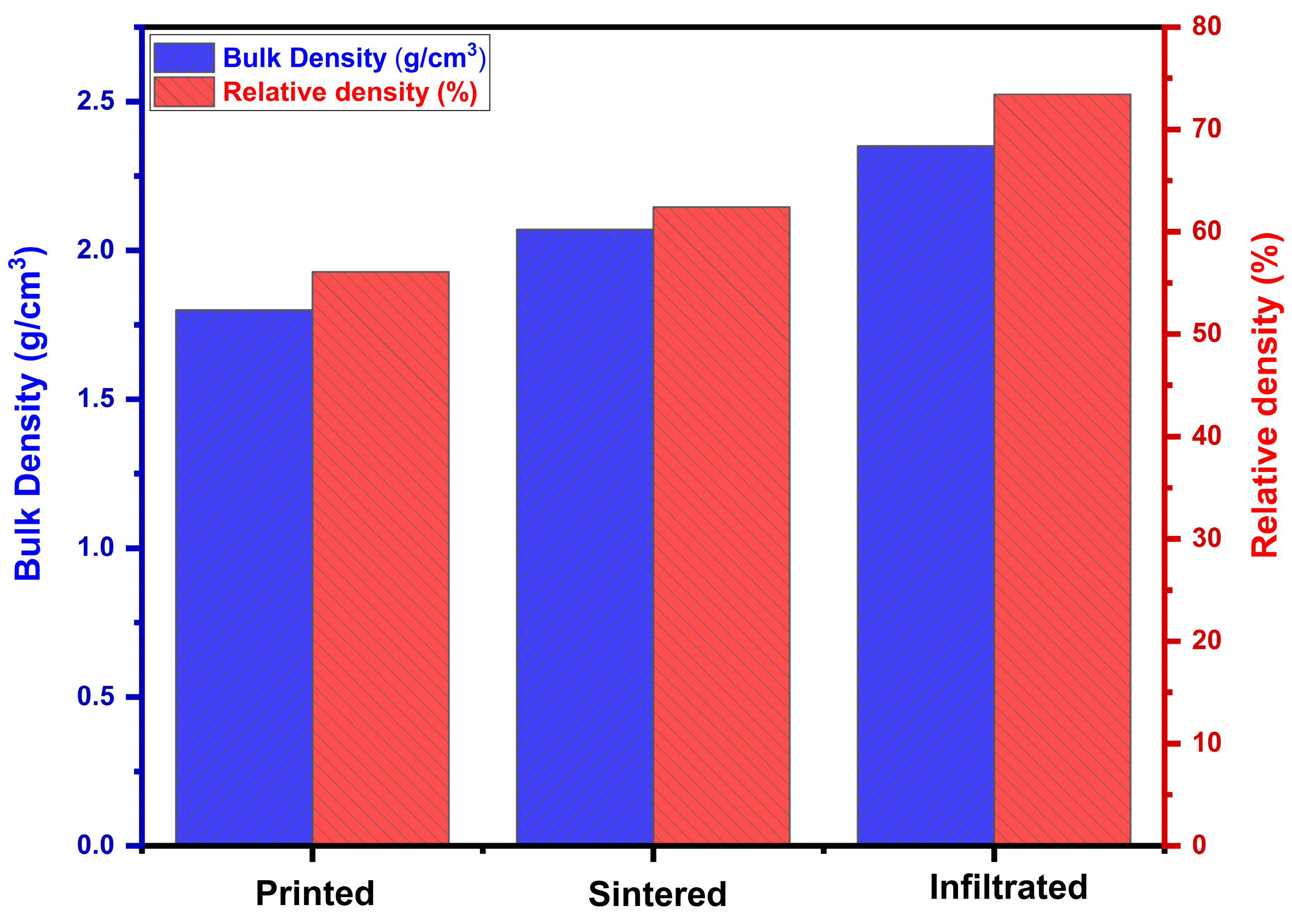
Figure 7.
XRD patterns of printed preform, sintered preform, and infiltrated preform.
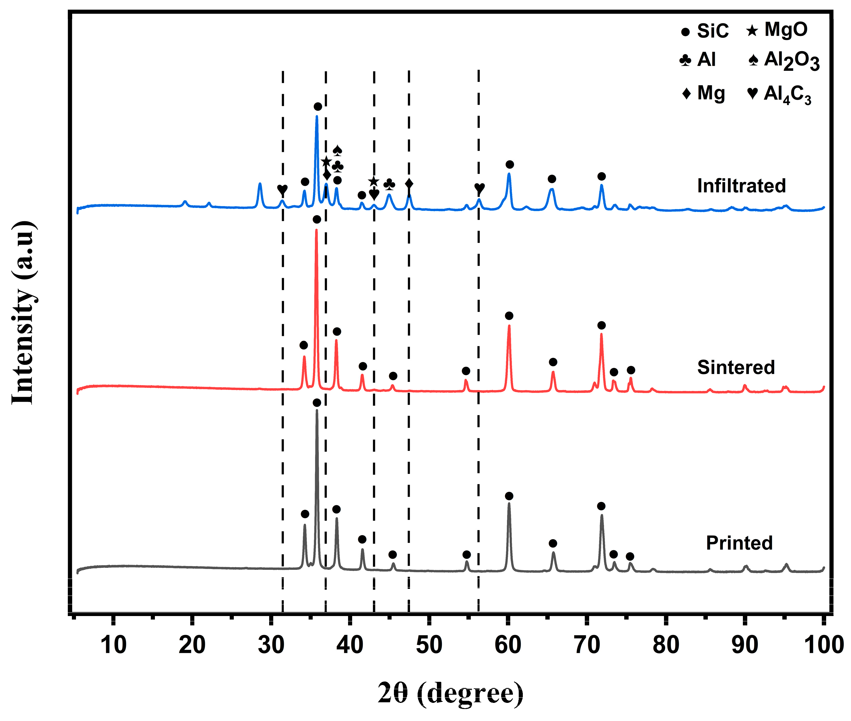
Figure 8.
Elemental mapping indicates presence of aluminum (Al) in infiltrated preform.
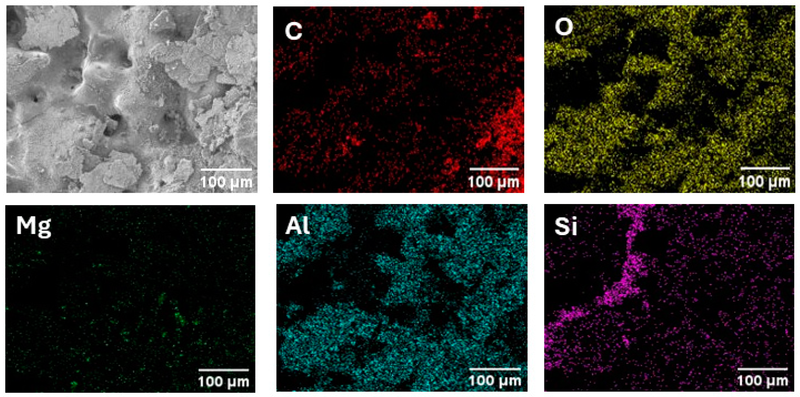

Table 1.
Printing parameters and their values used in binder jetting 3D printing.
| Printing Parameter | Value |
|---|---|
| Layer thickness (µm) | 45 |
| Compaction thickness (µm) | 35 |
| Ultrasonic intensity (%) | 100 |
| Roller traverse speed (mm/s) | 15 |
| Roller rotation speed (rpm) | 300 |
| Roughening roller rotation speed (rpm) | 50 |
| Binder saturation (%) | 60 |
| Binder set time (s) | 30 |
| Bed temperature (°C) | 50 |
| Drying time (s) | 15 |
| Packing rate (%) | 50 |
Disclaimer/Publisher’s Note: The statements, opinions and data contained in all publications are solely those of the individual author(s) and contributor(s) and not of MDPI and/or the editor(s). MDPI and/or the editor(s) disclaim responsibility for any injury to people or property resulting from any ideas, methods, instructions or products referred to in the content. |
© 2025 by the authors. Licensee MDPI, Basel, Switzerland. This article is an open access article distributed under the terms and conditions of the Creative Commons Attribution (CC BY) license (http://creativecommons.org/licenses/by/4.0/).
Copyright: This open access article is published under a Creative Commons CC BY 4.0 license, which permit the free download, distribution, and reuse, provided that the author and preprint are cited in any reuse.


