Preprint
Brief Report

This version is not peer-reviewed.

Systems Design and Experimental Study of a Solar Parabolic Trough for Solar Refrigeration

Submitted:

27 January 2025

Posted:

28 January 2025

Read the latest preprint version here

Abstract

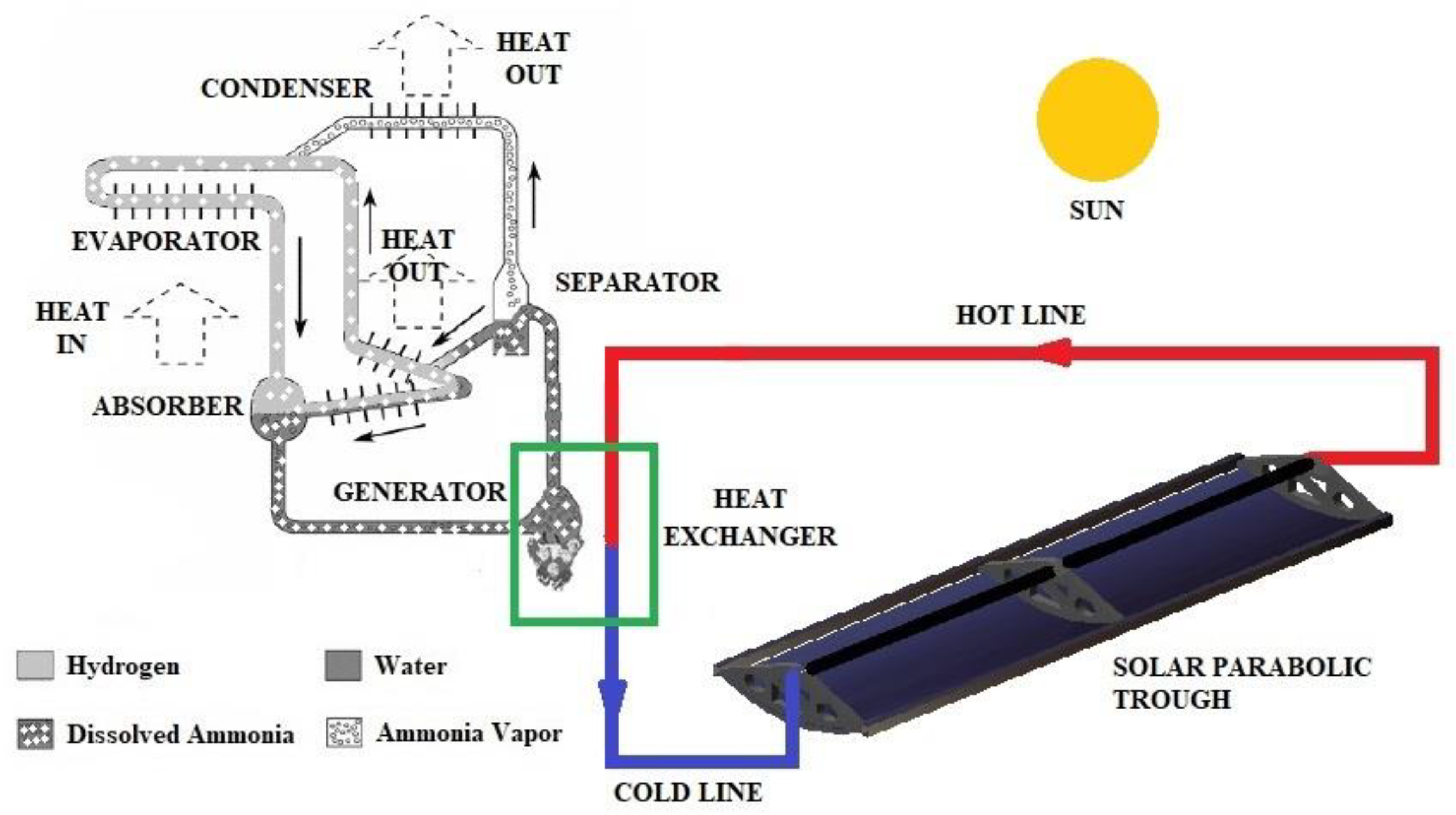
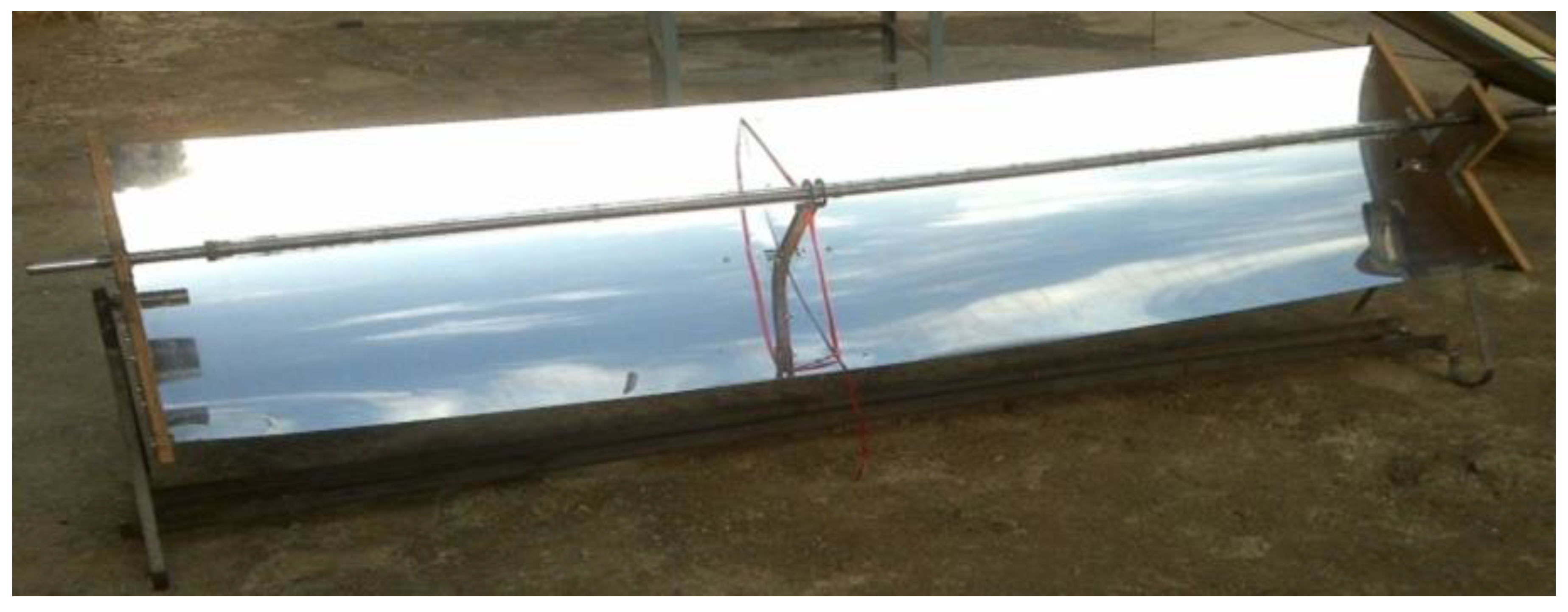
A solar parabolic trough is manufactured, and the data required in the analysis provided in the current work is recorded with the said apparatus. The trough is manufactured considering its use for solar refrigeration using triple fluid vapor absorption refrigeration system (TFVARS). In this method, the solar energy is converted to thermal energy in the form of a stream of hot-air generated at the receiver of a parabolic trough. This thermal energy is used to heat the generator of the TFVARS. In this way, the refrigeration effect is achieved. Additionally, a discussion on the tracking modes of the trough for best efficiency and ease in tracking, is provided. In this work, the solar parabolic trough is designed as per the requirements of the TFVARS refrigerator, and then conduct a series of tests for recording the trough’s performance parameters.

Keywords: 
;  ;  ;  

Introduction

The main objective of using solar refrigeration device is to provide cold storage in remote/rural areas where electricity is unavailable for continuous and everyday applications, especially in the under-developed and/or developing countries. Refrigeration has domestic applications and it is used in several industries, and it consumes significant power or electricity. It is required for storing vaccines and blood, and for storing few types of seeds, fertilizers, etc. Additionally, fish can also be stored immediately as soon as they are caught on ship, where the conventional method was fishing and then refrigerating the fishes on the port/shore. In the conventional process, the fish starts decomposing from the point of fishing till it is stored on port. Resultantly, the fish might be infected because of this delay. Solar refrigeration is the best option for the problems discussed above, and for reducing the use-phase electricity consumption compared to the conventional refrigeration, resultantly reducing the global warming/climate-change impacts of refrigeration. Solar refrigeration can be an alternative to all/most of the applications of refrigeration.
Previous studies by Ullah et al. [1], Cabrera et al. [2], Sarbu et al. [3], and Siddiqui et al. [4] are latest studies that are relevant to this work, and they review all methods of solar refrigeration in detail. However, these studies do not provide the design of the solar collector considered in each of these studies. The limitations of previous studies motivate this work. The scope and purpose of this work is to provide a design of a solar parabolic trough for an absorption type of refrigeration system, specifically a triple fluid vapor absorption refrigeration system; along with its test results. A solar parabolic trough is manufactured in-house (K.J. Somaiya College of Engineering [KJSCE]) and is tested, and its performance parameters are recorded. The authors also provide a discussion on the various tracking modes of this trough. This study will help researchers to design and self-manufacture a solar parabolic trough and apply it different systems which require thermal, mechanical or electrical energy as an input to their system. These systems and applications may include but are not limited to powering a sterling engine for mechanical/electrical energy, solar dryers, power an organic Rankine cycle to obtain work-output via turbo-expander etc. The above is the significance of this work.

Overview of Systems Involved

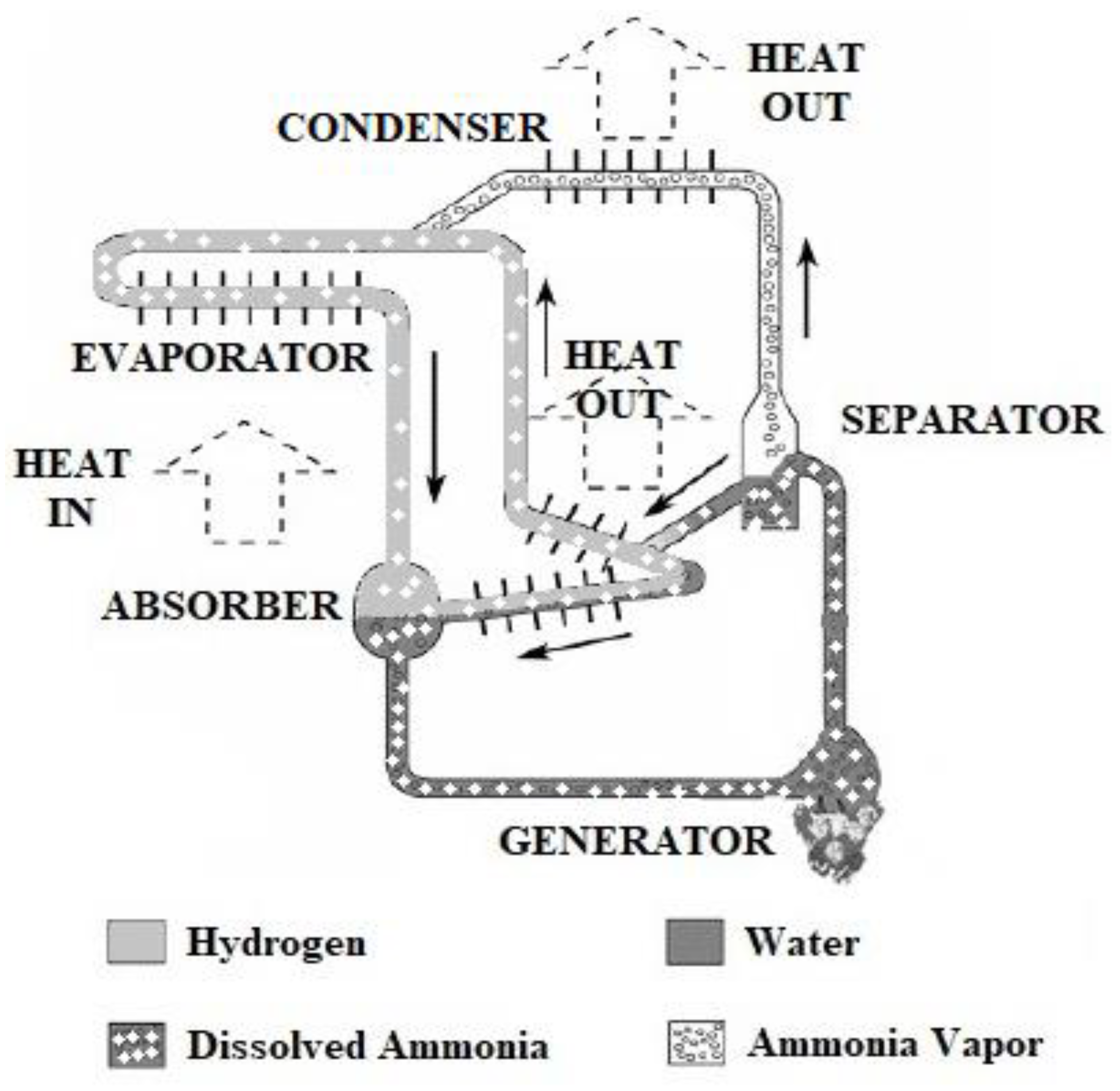
Triple Fluid Vapor Absorption Refrigeration System (TFVARS)

TFVARS uses ammonia as refrigerant, water as absorbent, and hydrogen as an inert gas. The total pressure is constant throughout system, thus eliminating the need for mechanical pump or compressor. To allow the refrigerant (ammonia) to evaporate at low temperatures in the evaporator, a third inert gas (hydrogen) is introduced into the evaporator-absorber of the system. Thus, even though the total pressure is constant throughout the system, the partial pressure of ammonia in evaporator is much smaller than the total pressure due to the presence of hydrogen obeying Dalton’s law of partial pressures. The Generator is conventionally heated by electric heaters [5]. Figure 1 shows a TFVARS and Figure 2 shows TFVARS coupled to a solar parabolic trough. The parabolic trough in Figure 2 is a design model made by the authors in CATIA.

Solar Thermal Collector

Different types of thermal collectors like paraboloid dish, cylindrical parabolic trough, and compound parabolic collector (CPC) were studied. The paraboloid dish is difficult in construction and it costs more. It requires too much precision in obtaining the focus of the paraboloid dish. Similarly, CPC construction is costly, and getting two intersecting parabolic surfaces as a reflective surface is cumbersome (from manufacturing perspective) [6]. A cylindrical parabolic trough which has a parabola (2D) extruded in the third dimension, is selected for this study (and for manufacturing). In this trough, the sunrays incident on the parabolic reflecting surface gets concentrated at the receiver (focus of the parabola) thereby heating the fluid (air in this study) passing through the receiver (pipe). The thermal energy of air is utilized to heat the generator of a TFVARS.

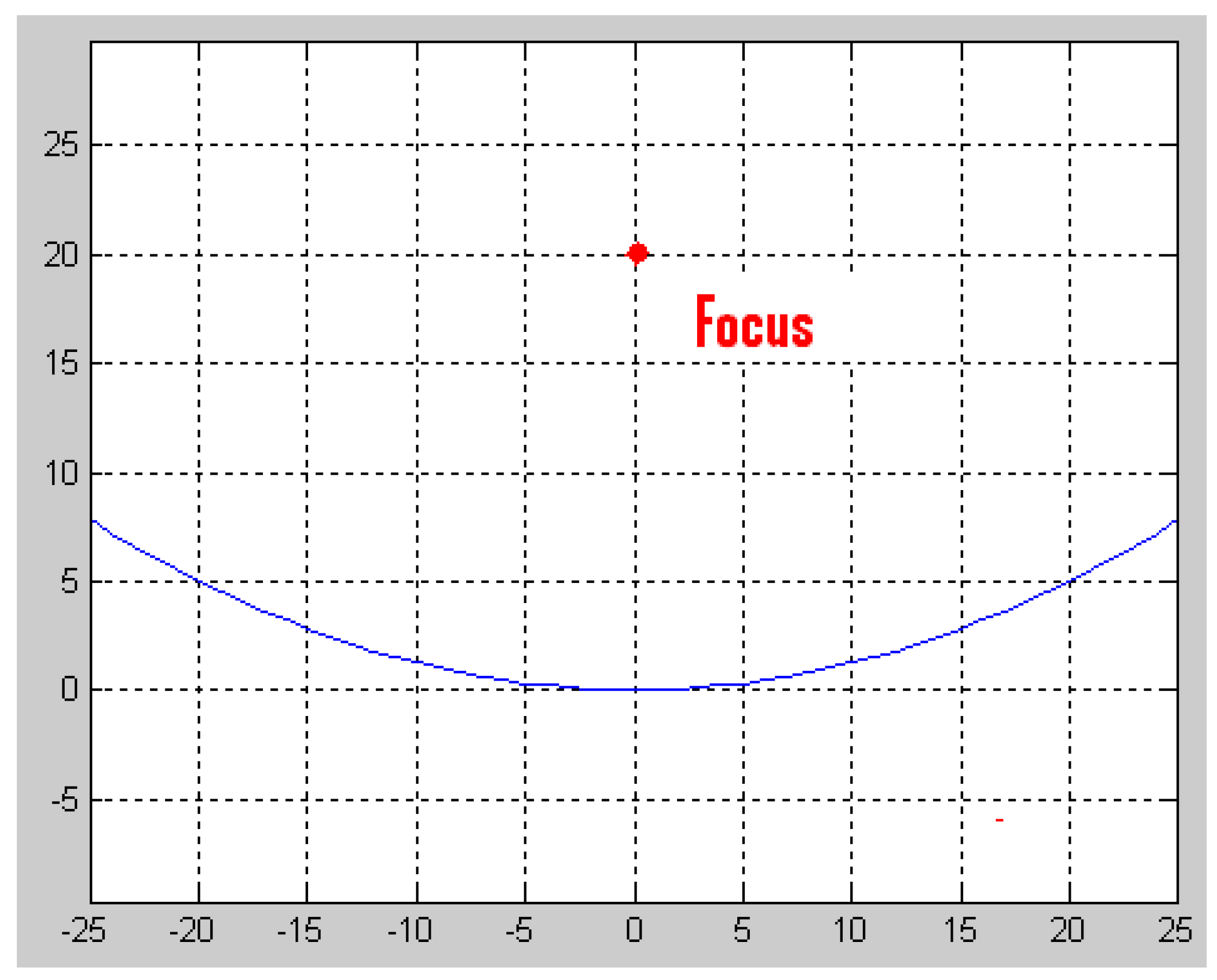
Design of Solar Parabolic Trough
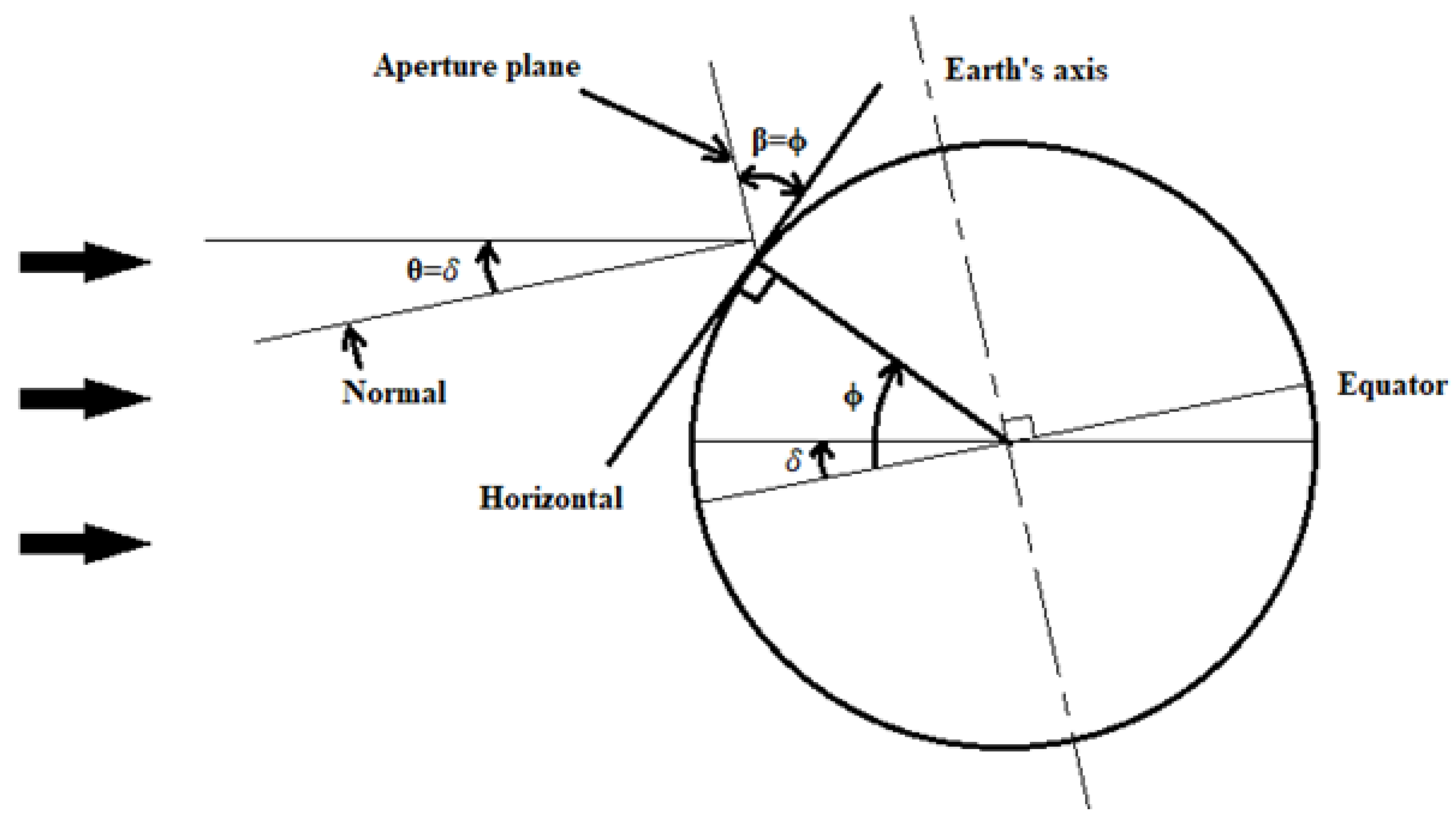
A reverse estimation approach was implemented for calculating the dimensions of the concentrator/trough, i.e. calculating the dimensions of trough from the performance of refrigerator. A test was conducted on a 41-liter TFVARS refrigerator and its coefficient of performance (COP) was calculated to be 0.23. From the electric meter readings, we require 60W power for refrigeration, which is supplied to the generator of TFVARS for heating by means of electric heaters.
A design factor of 4 is considered i.e. four times the required power, to take care of variation in solar energy. If generator input is more then we will get more cooling effect and there will be no disadvantage. Therefore, the trough is designed for power requirement of 4 x 60 = 240W. Let thermic fluid system efficiency be 50%. It includes loss in carrying fluid to heat exchanger, heat exchanger efficiency. Thus, heat supplied to thermic fluid is 240/0.5= 480W. Typically, the efficiency of solar parabolic collector is approximately 50% [6], but there are some studies which report efficiency of 73% [7]. The efficiency mainly depends on the selection of parabolic surface and the corresponding positioning of its receiver, reflectivity of the parabolic surface, evacuation of receiver pipe, and on the tracking system and mode [6]. Let solar concentrator efficiency be 60%. So solar concentrator should have a capacity of 480/0.6 = 800W. Maximum solar energy available on surface is 800 W/m 2 [6]. So, required area is A =800/800=1m2. Therefore, the author’s designed a trough of 1 m2 projected area. The width is 0.5 m, and length is 2 m. The designed parabolic equation is X2 = 80 Y and its profile is shown below in Figure 3. The concentration ratio is calculated to be 9.047 for receiver pipe (made of steel) of outer and inner diameter of 19 mm and 18.5 mm respectively. Figure 4 shows the actually-manufactured parabolic trough. The reflective surface is an acrylic mirror. Acrylic mirror is chosen for ease in manufacturing, as it is flexible and non-fragile compared to glass, and it has good reflectivity (~92%). For reducing heat loss due to convection, the receiver pipe is enclosed in a glass tube. Additionally, the receiver pipe is supported mid-way to prevent sagging (loss of focus/concentration of sunlight at the receiver). The total manufacturing cost of the solar parabolic trough is 6000 Indian rupees (equivalent to approximately US $100).

Tracking Modes

Before understanding the tracking modes, we need to first understand the angles, geometry and parameters used in the discussion ahead. These are shown on Figure 5.
θ is the angle of incidence, i.e. it is the angle between an incident beam of flux and the normal to the plane surface; Ø is latitude of a location, which is the angle made by radial line joining the location to the centre of earth with the projection of the line on the equatorial plane; β is the slope, which is the angle made by the plane surface with the horizontal; w is the hour angle, which is an angular measure of time and is equivalent to 150 per hour; θz is the zenith angle, which is the angle made by the sun’s rays with the normal to a horizontal surface; Ib is the intensity of incident sunlight in W/m2; rb is the tilt factor; Ib rb is the flux in W/m2; and δ is the declination, which is the angle made by the line joining the centres of the sun and the earth with the projection of this line on the equatorial plane [6].
There are five tracking modes which are described below. Equations (1)-(5) are taken from resource [6].
Mode I - The focal axis is East-West (E-W) direction and horizontal, and the collector is rotated about a horizontal E-W axis and adjusted once every day [6].
δ o = 23.45 sin [ 360 365 ( 284 + n ) ]
where n is day number in a year.
cos θ = (sin δ)2 + (cos δ)2 cos w
Mode II - The focal axis is horizontal and in the E-W direction, and the trough is rotated about a horizontal E-W axis and adjusted continuously [6].
cos θ = (1 − (sin w)2 (cos δ)2)1/2
Mode III - The focal axis is horizontal and in the North-South (N-S) direction, and the trough is rotated about a horizontal N-S axis [6].
cos θ = [(sin Ø sin δ + cos w cos δ cos Ø)2 + (cos δ)2(sin w)2]
Mode IV- The focal axis is inclined at a constant angle equal to the latitude and in N-S direction [6]. It is adjusted such that at solar noon the aperture plane is an inclined surface facing due south [6].
Mode V - The focal axis is N-S and inclined [6]. The trough is rotated continuously about an axis parallel to the focal axis, and about a horizontal axis normal to this axis and adjusted so that the solar beam is perpendicularly incident on the aperture plane at all times [6]. In this situation:
cos θ = 1

Solar Tracking Analysis for Kjsce Site

Analysis for KJSCE site (Mumbai, India) in the month of June with positions 19.0865o (N) and 72.904o (E) i.e. Ø=19.0865o and δ=23.5 o. Pyranometer (kept on a horizontal surface) readings taken for the Beam Intensity (Ib). Equation (6) is taken from resource [6].
cos θz = (sin Ø sin δ + cos w cos δ cos Ø)
Sample calculation for w=67.5o and tracking mode 1 using equation 2 and putting respective values cos θ = (sin δ)2 + (cos δ)2 cos w. Therefore, cos θz = 0.462 and cos θ = 0.48. Tilt factor rb = c o s θ c o s θ z = 1.039 Flux incident normally on the aperture plane Ibrb = 281(W/m2).
Similarly, calculations of all other modes can be done by using Equations (1)-(6). The results are recorded in Table 1. From Table 1, the above discussion and analysis of different systems we can conclude that the cylindrical parabolic trough in Mode III is an excellent system. This mode is used because of the ease in tracking. Also, the flux incident normally on the aperture plane is higher in comparison with other modes, considering the ease in tracking.

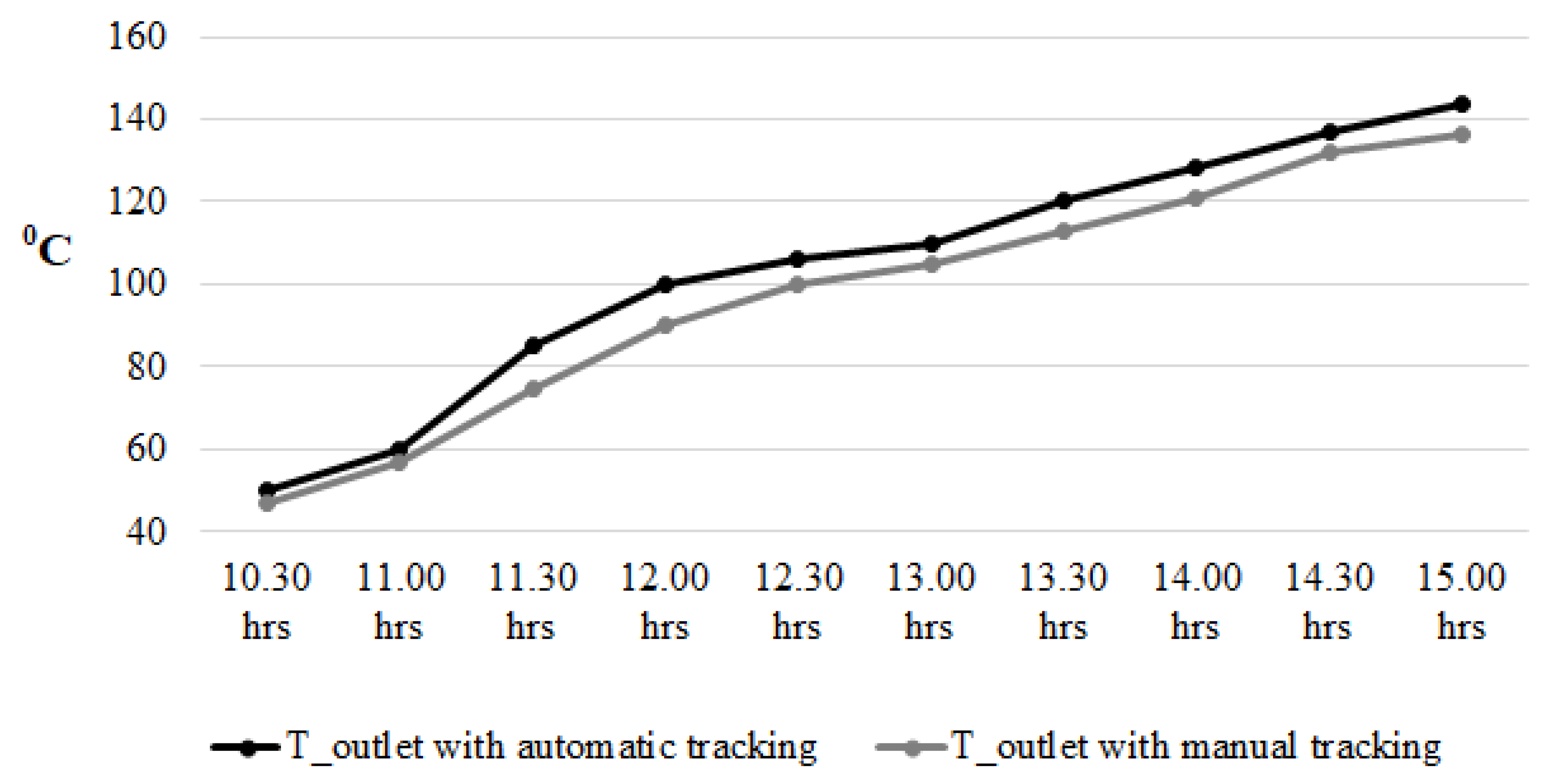
Results and Discussion

A test is conducted on the manufactured solar parabolic trough in the month of March at KJSCE site (Mumbai, India). The trough tracking mode is Mode III. Air is used as a thermic fluid passing through the receiver of the trough, and it is supplied by means of an air blower. The mass flow rate of air in this test is 10kg/hr. An automatic tracking system (electronic system) is used in the trough. A comparative study is conducted to examine the effect of installation of tracking mechanism, with time. For manual tracking, the trough was adjusted manually such that the focus (line in 3D) was observed on the receiver. The result of this comparative study is shown in Figure 6. Installing the tracking mechanism increases the temperature of air flowing through the receiver.
Table 2 shows the recorded data from test on the trough, along with performance calculations (with a trough area of 1m2). This test was conducted on the trough with automated tracking installed on it in Mode III. The power/energy required at the generator of the 41-liter TFVARS described above is 60W. From Table 2 it can be observed that the trough can avail thermal energy (via air as thermal fluid) of at least 200W and a maximum of approximately 290W. The ideal effectiveness of a simple counter-flow heat exchanger (CFHE) is 100%, and in real applications it has significantly higher effectiveness and efficiency [8,9]. A CFHE is ideal for this application. A detailed design of a heat exchanger is out of the scope of this work. An assumed/worst-case heat transfer performance of 50% by the CFHE will still avail at least 100W of energy-power to the generator, thereby providing the required energy to perform refrigeration.

Conclusions

In this paper, the authors provide the design of a solar parabolic trough to be used for solar refrigeration. The refrigeration method used for this application is an absorption type of refrigeration system, specifically a TFVARS. A solar parabolic trough was manufactured with the help of this design. The trough underwent a series of tests and data was collected for the same. The trough’s performance parameters were evaluated based on this data. The thermal energy available with the thermic fluid i.e. air in this work, is found sufficient, to power the 41-liter TFVARS, thereby validating the design process of the parabolic trough. This work motivates a follow-up study on the detailed design of a heat exchanger between generator and the thermic fluid. The manufactured solar parabolic trough will be able to sufficiently power the said refrigerator, thereby providing solar refrigeration.

Acknowledgements

The authors are thankful to Sandeep Shah, Ketan Tank, and Mumal Rathore for their help during a part of this work. First author’s other research work can be found in [10,11,12,13,14,15,16,17,18,19,20,21,22,23,24,25,26,27,28,29,30,31,32,33,34,35,36,37,38,39,40].

Conflicts of Interest

On behalf of all authors, the corresponding author states that there is no conflict of interest. The authors declare that they have no conflict of interest.

Supporting Data Statement

All data is provided in this manuscript, and no separate supplementary data (in any form) is required to be provided along with this manuscript.

References

  1. K. R. Ullah, R. Saidur, H. W. Ping, R. K. Akikur, and N. H. Shuvo, “A review of solar thermal refrigeration and cooling methods,” Renew. Sustain. Energy Rev., vol. 24, pp. 499–513, Aug. 2013. [CrossRef]
  2. F. J. Cabrera, A. Fernández-García, R. M. P. Silva, and M. Pérez-García, “Use of parabolic trough solar collectors for solar refrigeration and air-conditioning applications,” Renew. Sustain. Energy Rev., vol. 20, pp. 103–118, Apr. 2013. [CrossRef]
  3. I. Sarbu and C. Sebarchievici, “Review of solar refrigeration and cooling systems,” Energy Build., vol. 67, pp. 286–297, Dec. 2013. [CrossRef]
  4. M. U. Siddiqui and S. A. M. Said, “A review of solar powered absorption systems,” Renew. Sustain. Energy Rev., vol. 42, pp. 93–115, Feb. 2015. [CrossRef]
  5. C. P. Arora, Refrigeration and Air Conditioning.
  6. S. P. Sukhatme, “Solar energy: principles of thermal collection and storage,” 1996.
  7. A. H. A. Al-Waeli, H. A. Kazem, M. T. Chaichan, and K. Sopian, “Photovoltaic/thermal (PV/T) systems: Principles, design, and applications,” Photovoltaic/Thermal Syst. Princ. Des. Appl., pp. 1–282, Oct. 2019. [CrossRef]
  8. Fakheri, “Heat Exchanger Efficiency,” J. Heat Transfer, vol. 129, no. 9, pp. 1268–1276, Sep. 2007. [CrossRef]
  9. T. L. Bergman and D. P. DeWitt, “Fundamentals of Heat and Mass Transfer,” 2012, Accessed: Jan. 20, 2025. [Online]. Available: https://books.google.com/books/about/Fundamentals_of_Heat_and_Mass_Transfer.html?id=vvyIoXEywMoC.
  10. S. S. Jagtap, “An Apparatus for Exchanging Heat with Flow in an Annulus,” J. Eng. Sci. Technol. Rev., vol. 10, no. 1, pp. 173–176, 2017, Accessed: Jan. 11, 2019. [Online]. Available: http://www.jestr.org/downloads/Volume10Issue1/fulltext241012017.pdf.
  11. S. S. Jagtap, “A heat recovery system for shaft-driven aircraft gas turbine engines,” Oct. 29, 2014.
  12. S. S. Jagtap, “A heat recovery system designed for shaft-powered aircraft gas turbine engines,” 2016.
  13. S. S. Jagtap, “Sustainability assessment of hydro-processed renewable jet fuel from algae from market-entry year 2020: Use in passenger aircrafts,” in 16th AIAA Aviation Technology, Integration, and Operations Conference, Jun. 2016. [CrossRef]
  14. L. Emerson, S. Jagtap, and T. C. Lieuwen, “Stability Analysis of Reacting Wakes: Flow and Density Asymmetry Effects,” in 53rd AIAA Aerospace Sciences Meeting, Jan. 2015. [CrossRef]
  15. Emerson, S. Jagtap, J. M. Quinlan, M. W. Renfro, B. M. Cetegen, and T. Lieuwen, “Spatio-temporal linear stability analysis of stratified planar wakes: Velocity and density asymmetry effects,” Phys. Fluids, vol. 28, no. 4, p. 045101, Apr. 2016. [CrossRef]
  16. S. S. Jagtap, “Comparative assessment of manufacturing setups for blended sugar-to-aviation fuel production from non-food feedstocks for green aviation,” in AIAA Propulsion and Energy 2019 Forum, 2019. [CrossRef]
  17. S. S. Jagtap, “Evaluation of blended Fischer-Tropsch jet fuel feedstocks for minimizing human and environmental health impacts of aviation,” in AIAA Propulsion and Energy 2019 Forum, 2019. [CrossRef]
  18. S. S. Jagtap, “Assessment of feedstocks for blended alcohol-to-jet fuel manufacturing from standalone and distributed scheme for sustainable aviation,” in AIAA Propulsion and Energy 2019 Forum, 2019. [CrossRef]
  19. S. S. Jagtap, P. R. N. Childs, and M. E. J. Stettler, “Performance sensitivity of subsonic liquid hydrogen long-range tube-wing aircraft to technology developments,” Int. J. Hydrogen Energy, vol. 50, pp. 820–833, Jan. 2024. [CrossRef]
  20. S. S. Jagtap, P. R. N. Childs, and M. E. J. Stettler, “Conceptual design-optimisation of a future hydrogen-powered ultrahigh bypass ratio geared turbofan engine,” Int. J. Hydrogen Energy, vol. 95, pp. 317–328, Dec. 2024. [CrossRef]
  21. S. S. Jagtap, M. E. J. Stettler, and P. R. N. Childs, “Data in brief: Energy performance evaluation of alternative energy vectors for subsonic intercontinental tube-wing aircraft”.
  22. S. Jagtap, A. Strehlow, M. Reitz, S. Kestler, and G. Cinar, “Model-Based Systems Engineering Approach for a Systematic Design of Aircraft Engine Inlet,” in AIAA SCITECH 2025 Forum, 2025. [CrossRef]
  23. S. S. Jagtap, “Non-food feedstocks comparison for renewable aviation fuel production towards environmentally and socially responsible aviation,” in 2019 AIAA Propulsion & Energy Forum, 2019.
  24. S. S. Jagtap, P. R. N. Childs, and M. E. J. Stettler, “Conceptual design-optimisation of a subsonic hydrogen-powered long-range blended-wing-body aircraft,” Int. J. Hydrogen Energy, vol. 96, pp. 639–651, Dec. 2024. [CrossRef]
  25. S. S. Jagtap, “Systems evaluation of subsonic hybrid-electric propulsion concepts for NASA N+3 goals and conceptual aircraft sizing,” Int. J. Automot. Mech. Eng., vol. 16, no. 4, pp. 7259–7286, 2019. [CrossRef]
  26. S. S. Jagtap, “Evaluation of technology and energy vector combinations for decarbonising future subsonic long-range aircraft,” Imperial College London.
  27. S. S. Jagtap, M. E. J. Stettler, and P. R. N. Childs, “Data in brief: Performance sensitivity of subsonic liquid hydrogen long-range tube-wing aircraft to technology developments”.
  28. S. S. Jagtap, M. E. J. Stettler, and P. R. N. Childs, “Data in brief: Conceptual design-optimisation of futuristic hydrogen powered ultrahigh bypass ratio geared turbofan engine”.
  29. S. S. Jagtap, M. E. J. Stettler, and P. R. N. Childs, “Data in brief: Conceptual design-optimisation of a subsonic hydrogen-powered long-range blended-wing-body aircraft”.
  30. S. S. Jagtap, “Aero-thermodynamic analysis of space shuttle vehicle at re-entry,” IEEE Aerosp. Conf. Proc., vol. 2015-June, Jun. 2015. [CrossRef]
  31. S. Jagtap and S. Bhandari, “Solar Refrigeration,” Sardar Patel Int. Conf., 2012, [Online]. Available: https://papers.ssrn.com/sol3/papers.cfm?abstract_id=2103115.
  32. S. Jagtap and S. Bhandari, “Solar Refrigeration using Triple Fluid Vapor Absorption Refrigeration and Organic Rankine Cycle,” in Sardar Patel International Conference SPICON 2012 Mechanical, 2012.
  33. N. Komerath, S. Jagtap, and N. Hiremath, “Aerothermoelastic Tailoring for Waveriders,” in US Air Force Summer Faculty Fellowship Program, 2014.
  34. S. S. Jagtap, “Exploration of sustainable aviation technologies and alternative fuels for future inter-continental passenger aircraft.”.
  35. S. S. Jagtap, “Identification of sustainable technology and energy vector combinations for future inter-continental passenger aircraft.”.
  36. S. S. Jagtap, “Heat recuperation system for the family of shaft powered aircraft gas turbine engines,” US10358976B2, 2019 [Online]. Available: https://patents.google.com/patent/US10358976B2/en.
  37. S. S. Jagtap, “Heat recovery system for shaft powered aircraft gas turbine engines”.
  38. S. S. Jagtap and S. Bhandari, “Systems design and experimental study of a solar parabolic trough for solar refrigeration”.
  39. S. S. Jagtap, “Conceptual aircraft sizing using systems engineering for N+3 subsonic hybrid-electric propulsion concepts”.
  40. S. S. Jagtap, P. R. N. Childs, and M. E. J. Stettler, “Energy performance evaluation of alternative energy vectors for subsonic long-range tube-wing aircraft,” Transp. Res. Part D Transp. Environ., vol. 115, p. 103588, Feb. 2023. [CrossRef]
Figure 1. TFVARS schematic diagram.
Preprints 147437 g001
Figure 2. TFVARS coupled to a solar parabolic trough.
Preprints 147437 g002
Figure 3. Parabola profile.
Preprints 147437 g003
Figure 4. Manufactured solar parabolic trough.
Preprints 147437 g004
Figure 5. Solar geometry.
Preprints 147437 g005
Figure 6. Effect of tracking mechanism on the temperature of air at receiver outlet.
Preprints 147437 g006
Table 1. Normal incident flux calculations.
Time Intensity
Ib(W/m2)
Hour angle Mode I
Ibrb (W/m2)
Mode II
Ibrb (W/m2)
Mode III
Ibrb (W/m2)
Mode IV
Ibrb (W/m2)
Mode V
Ibrb (W/m2)
7.30 am 270 67.5 281 310.23 564.03 535.95 584.55
10 am 510 30 513.57 514.59 574.77 530.91 578.85
12 noon 603 0 604.80 604.809 603 554.96 604.809
3 pm 340 -45 344.42 348.16 451.18 419.56 457.64
5.30 pm 298 -82.5 328.694 335.176 430.53 400.96 435.34
Table 2. Trough performance test and calculations.
Time
I(PM)
Tilt factor Radiation (W/m2) Temperature (0C) Heat absorbed (W/m2) Efficiency (%)
Total Diffusive Incident Flux Incident Output Input Rise
12:00 0.981 778 255 523 513.06 101 27 74 208.23 40.59
12.45 1.001 823 272 551 551.55 108 30 78 219.48 39.79
1.45 1.104 791 235 556 613.82 122 32 90 253.25 41.26
2.45 1.339 719 190 529 708.33 132 33 99 278.58 39.33
3.15 1.5 610 173 437 655.50 136 32 104 292.64 44.64
4.15 2.179 408 126 282 614.48 133 32 101 284.20 46.25
Disclaimer/Publisher’s Note: The statements, opinions and data contained in all publications are solely those of the individual author(s) and contributor(s) and not of MDPI and/or the editor(s). MDPI and/or the editor(s) disclaim responsibility for any injury to people or property resulting from any ideas, methods, instructions or products referred to in the content.
Copyright: This open access article is published under a Creative Commons CC BY 4.0 license, which permit the free download, distribution, and reuse, provided that the author and preprint are cited in any reuse.
Prerpints.org logo

Preprints.org is a free preprint server supported by MDPI in Basel, Switzerland.

Subscribe

Disclaimer

Terms of Use

Privacy Policy

Privacy Settings

© 2025 MDPI (Basel, Switzerland) unless otherwise stated