Submitted:
20 January 2025
Posted:
20 January 2025
You are already at the latest version
Abstract
In the harvesting operation, the stubble height of the grain is an important parameter index in the combine harvesting operation, the stubble is too high or too low will directly affect the harvesting quality and the service life of the cutting table. At present, the profiling control system can only control the lift of the cutting table in the vertical direction, but not the horizontal direction and the angle of the cutter profiling. The purpose of this study is to propose a contouring control strategy and system for grain harvesting by analyzing the designed contouring adjustment mechanism, and to simulate the control method and hydraulic system through Amesim software to simulate and analyze the control method and hydraulic system. Finally, different forward speeds of the harvester (5、7、9、11km/h) and different cutting heights of the harvester were analyzed based on static and field tests and different stubble heights (100、150、200、250mm) on the test indexes. The results of the field test showed that for different operating speeds, the error between the mean value of stubble height and the target value was small, and the absolute error was less than 2mm, the mean value of the coefficient of variation of stubble height was 4.53% and the mean value of control accuracy is 94%.The developed adaptive control system of the profiled grain cutting deck has high accuracy and stability, which can provide reference for the all-terrain profiling control technology of combine harvester cutting deck.
Keywords:
Combined grain harvester
; Cutting table profiling
; Hydraulic control systems
; Field trial
1. Introduction
It is important to ensure consistent stubble height on combine harvesters in complex operating conditions. Too high a stubble height can result in the cutting deck being overfed with too much straw, causing blockages that increase the load on the cutting deck, resulting in wasted energy and also affecting the subsequent threshing and cleaning process[1]. In addition, too high a stubble will also affect the subsequent cultivation, resulting in unnecessary energy waste and increased labor. And in the grain harvesting operation, the cutting angle of the cutter along with the cutting platform of the shape is also changing. There are nearly 700 million mu of hilly and mountainous farmland in China, and its terrain has a large slope[2]. Therefore, it is difficult for the combine harvester to ensure the consistency of the stubble height during the harvesting operation, which results in the decline of harvesting quality. At present, the grain combine harvester by manually adjusting the vertical lift of the cutting platform for simple height profiling, which greatly increases the labor intensity of the operator; and because of the complexity of its hilly and mountainous terrain, so it can not guarantee the accuracy and stability of its harvesting. In recent years, with the automation of agricultural machinery, intelligent development, the existing grain combine harvester manually adjust the height of a single cutter imitation has been unable to meet market demand[3]. Therefore, this paper develops an adaptive control system for grain cutting table profiling adapted to the operation of hilly and mountainous areas in China.
The height profiling adjustment of the existing grain combine harvester cutting deck is accomplished by the execution of hydraulic cylinders; therefore, in order to improve the stability and accuracy of the hydraulic control system during the height profiling of the cutting deck, scholars have conducted extensive research on the harvester cutting deck adjustment. For example, Wang et al . [4] proposed an intelligent control algorithm for cutting deck profiling based on multi-sensor data fusion and model predictive control, which can accurately perform cutting deck height profiling, and also designed a hydraulic control system for cutting deck height profiling. The field test shows that the average value of coefficient of variation is 3.5% under different operating speeds, and the average control accuracy of the cutting deck is 91.5%, and this control system has high precision and stability, which provides a certain reference value for the height profiling of the cutting deck. Ni et al . [5] designed an adaptive cutting platform height adjustment system by kinematically analyzing the interaction between the profiling mechanism and soil, establishing a mathematical model of the angle sensor and the profiling mechanism, and providing a basis for the acquisition of terrain information for the subsequent profiling cutting platform control system. Geng et al . [6] designed a floating compression type profiling mechanism and automatic profiling regulation technology for the domestic corn harvester cutting platform through manual control, and the study determined the torque parameter of the torsion spring of the key mechanism of the profiling mechanism as 15N/m. The study determined the torsion parameters of the key mechanism of the profiling mechanism as , which provided a reference for the design of the subsequent profiling mechanism of the cutting deck. Liu et al . [7] for the existing harvesting machinery can not guarantee the stubble height consistency of regenerated rice this problem, the study designed an adaptive profiling cutting platform, and based on the PID fuzzy control method of its simulation performance test; the results show that the cutting platform height and leveling adjustment of the average error for the 6.75mm,0.64°, which can meet the harvesting of regenerated rice. G.T.Lopes et al. [8] conducted a research on the problem of dead zone in the existing harvester cutting deck profiling control system. By analyzing the dynamics of the combine harvester cutting deck, the space state equations of the cutting deck height were derived, and a linear quadratic Gaussian control method with loop transfer response was proposed to improve the performance of the cutting deck profiling control. However, the study only conducted simulation tests and did not conduct field profiling tests to verify the stability of the machine. Zhang et al . [9]. developed a control system for adaptive mimicry of stalk-and-cob fresh corn harvesting cutter, which used an ultrasonic wave distance sensor for ground information acquisition. However, the stability of ultrasonic sensors operating in complex fields with many obstacles is greatly challenged. To ensure the stubble height for grain harvesting and to reduce grain loss, Wang et al . [10] designed an adaptive mimicry control system for cutter height based on PID and fitted a mathematical relationship between the cutter height and the voltage signal. However, the traditional PID control may be difficult to provide optimal control for nonlinear systems. Li et al . [11] designed a mechanical-hydraulic combined soybean cutting table profiling mechanism to improve its profiling range for the limited profiling range of soybean cutting table. And the mathematical model between the hydraulic cylinder expansion and the height of the cutter from the ground was constructed, which provides a theoretical basis for the adaptive profiling of the cutting table. Yang et al . [12] designed an adaptive height profiling control system and proposed a new EVPIVS-PID algorithm by analyzing the traditional PID algorithm and conducted simulations and field tests. The results show that based on EVPIVS-PID algorithm of the cutting table profiling control system has a working error of no more than 2mm and can meet its 5-11 company the harvesting speed.
Through the analysis of the above literature, it is found that most of the current research on grain combine harvester cutting deck profiling focuses on vertical height profiling, and does not consider the profiling of the cutting deck in the horizontal direction; the cutting angle of the combine harvester cutting deck cutter in the harvesting operation for the quality of the harvest and harvesting power consumption has an important impact, and the existing profiling control system research did not consider the impact of its influence[13]. For the hilly and mountainous areas with highly complex terrain, it is difficult to meet the accuracy and stability of harvesting with a single-height control system. Therefore, this paper through the grain combine harvester operation of the field terrain, the bridge state, the state of the cutting platform and the height of the cutting knife from the ground analysis, constructed the cutting platform in the harvesting operation of the vertical lift, horizontal swing and the cutting knife angle of the imitation of the mathematical model, put forward a kind of adaptive imitation of the shape of the control strategy, and according to the strategy designed for the hilly mountainous areas of the cutting platform adaptive imitation of the hydraulic control system, through the joint simulation and hydraulic system and carry out the control system, and then the control system of the hilly mountainous areas, and then the control system of the hilly mountainous areas. Through the joint simulation of the hydraulic system and field test to verify the accuracy and stability of the adaptive control system, to provide a reference for the automation and intelligentization of the cutting platform of the grain combine harvester.
2. Materials and Methods
2.1. Adaptive Conformal Adjustment Mechanism Design
According to the grain combine harvester operation law design as shown in Figure 1.the imitation grain cutting table adaptive adjustment mechanism mainly consists of vertical lifting hydraulic cylinder, bridge, cutting angle adjustment hydraulic cylinder, adjustment device, horizontal swing hydraulic cylinder, cutting table, angle sensor and imitation mechanism. As the key component of the control system, the adjusting device connects the cutting table with the bridge dynamically, so as to realize the swinging of the cutting table in the horizontal direction through the horizontal swinging hydraulic cylinder and the adjustment of the angle of the cutting angle through the cutting angle adjusting hydraulic cylinder to realize the adjustment of the angle of the reciprocating cutter. The vertical lifting hydraulic cylinder is articulated with the bridge to realize the vertical lifting movement of the cutting table.
The profiling mechanism mainly consists of a profiling rod, a fixed bracket, a torsion spring, a driving rod, a connecting rod, and a sensor driving plate[14]. The profiling rod and the driving rod are connected by bolts and hinged on the fixed bracket of the profiling rod. The torsion spring is installed between the profiling rod and its fixed bracket, and the torsion spring ensures that the profiling mechanism is in contact with the ground, so as to collect ground information. The angle sensor mainly collects the ground information, the real-time state of the cutting table and the height of the center of the cutting table from the ground, and transmits the collected information to the controller in the form of electric signals. Through the above-designed adaptive adjustment mechanism of the profiling grain cutting table, the profiling cutting table of the grain combine harvester can be profiled in real time during harvesting operation.
2.2. Modeling of Adaptive Conformal Adjustment Mechanisms
Kinematic analysis is a branch of mechanics that describes the law of change of the position of an object over time, based on the study of the motion of a mass or a rigid body, the study of the motion of an object does not involve the external forces on the object, and only studies the motion response caused by these forces[15,16]. The adaptive affine adjustment mechanism is simplified as a fixed-axis rotating rigid body around the point, in which the adjustment of the cutting angle of the reciprocating cutter is simplified as a fixed-axis rotating rigid body around the point. The imitation of the grain cutting table in the horizontal direction is simplified as a fixed-axis rotating rigid body around the point, so as to establish the imitation of the cutting table in the vertical direction of lifting and lowering, the horizontal direction of rotary oscillation and front and back direction of rotary floating three degrees of freedom of the motion relationship, as well as the height of the cutter from the ground, the cutting angle and the hydraulic cylinder expansion and contraction amount of the motion relationship. The simplified model of the adaptive profiling adjustment mechanism of the profiling grain cutting table is shown in Figure 2.
a. Vertical lifting motion and cutting angle adjustment
The cutting angle and vertical movement of the imitation grain cutting table are controlled by the cutting angle adjustment hydraulic cylinder and the vertical lifting hydraulic cylinder expansion and contraction, respectively. point is the dynamic connection point between the over-axle and the machine body to realize the vertical lifting and lowering of the imitation grain cutting table, point is the foremost part of the reciprocating cutter's movable blade, point is the dynamic connection point between the cutting table and the over bridge is the dynamic connection point of the cutting table and the bridge, realizing the adjustment of the cutter angle of the imitation grain cutting table, point and point are the fixed articulation points of the cutting angle adjusting hydraulic cylinder and the vertical lifting hydraulic cylinder respectively, point and point are the The active articulation point, then the cutting angle adjustment hydraulic cylinder telescoping length and lifting hydraulic cylinder length telescoping through the cosine theorem can be directly expressed as:
The relationship between, and can be derived using geometric relationships:
And as an intermediate quantity between the change in the angle of the cutter and the change in the vertical lift motion can be expressed as:
where is a corresponding cutting angle given for different crops, is real-time angle data of the reciprocating cutter's moving blade relative to the ground collected by an angle sensor, and is a given stubble height of the crop to be harvested(the distance from the ground to the tip of the moving blade of the reciprocating cutter) , is the distance from the point where the overbridge meets the body to the ground.
By substituting the parameters of the designed adaptive adjustment mechanism of the profiled grain cutting table into the above relations and substituting the above relations (3), (4) and (5) by substituting (1) and (2) one can get The relationship equation between the lifting movement of the imitation grain cutting table in the vertical direction and the cutter angle adjustment hydraulic cylinders and and the height of the cutting table is:
b. Horizontal rotary oscillating motion
The rotary swing of the profiling grain cutting table in the horizontal direction is mainly determined by the heights and of the left and right sides of the cutting table from the ground, where is the distance between the center of the profiling rods on the outside of the profiling mechanism mounted on the bottom left and right sides of the cutting table, is the horizontal angle of the cutting table from the ground (i.e., the angle of change of the cutting table from the level of the table), and is the initial angle of the fixed mounting seat of the hydraulic cylinder from the point of rotation and the movable hydraulic cylinder at the time when the cutting table is at the horizontal position. is the initial angle of the hydraulic cylinder fixed mount from the rotation point and the hydraulic cylinder movable articulation point in the horizontal position of the cutting platform, is the initial length of the horizontal swing hydraulic cylinder, and is the adjusted length of the horizontal swing hydraulic cylinder.
According to the simplified model of Figure 3 the relationship between and and can be obtained as: Kinematic modeling of the regulating mechanism in the horizontal direction.
The adjusted hydraulic cylinder length can be further obtained from the cosine theorem as:
Then, substituting the parameters of the designed adaptive adjustment mechanism of the profiled grain cutting table into the above relationship equation can be obtained that the relationship between the change amount of the transverse hydraulic cylinder and the heights of the left and right sides of the cutting table, and , is as follows:
2.3. Overall Design of Adaptive Profiling Control System
2.3.1. Analysis of Affine Control Strategies
The profiling mechanism, as the source of the input signal of the control system, has a correlation between the amount of change in the profiling angle and the amount of change in the height of the ground and the angle of rotation of the angle sensor in the harvesting operation carried out by the grain harvester. According to the motion characteristics of the profiling mechanism, the profiling rod is dragged during the forward movement of the harvester and will rotate under the action of the support force of the undulating terrain, generating the profiling angle. After a certain slope, the motion state is shown in Figure 4 (a):
Constructing a parallelogram in the coordinate system, the relationship equation between the change in height and the change in the affine angle for the back and forth back and forth movement is:
Also according to the position of the profiling mechanism mounted on the cutting table, the relationship between and is shown in Figure 4(a):
where is the given stubble height and is the effective imitation length of the imitation bar.
The process of acquiring the angle signal of the affine mechanism by the affine angle sensor can be viewed as a mechanism with two links as shown in Figure 4 (b). The articulated four-link mechanism can be viewed as a closed vector polygon where , , and are vectors of each component. According to Ni et al[5] . study, the affine angle will be defined as a positive value in the x-axis counterclockwise and expressed in complex form as:
where is the fixed angle between the drive rod and the profiling rod, is the angle between the connecting rod and the line connecting the fixed center of the profiling rod and the center of the sensor pendulum, and is the sensor acquisition angle (the angle between the pendulum and the line connecting the fixed center of the profiling rod and the center of the sensor pendulum). Expanding the equation through Euler's formula has:
The basic parameters of the profiling mechanism used in this paper are obtained by substituting them into the above equation:
As a result, the angle sensor will collect the cutting angle , the sensor angles and on the left and right sides of the cutting table, analyze and compare the current state of the cutting table by the adaptive affine algorithm written in the above principle, and calculate the actual heights of the current left and right sides of the cutting table, and , and analyze the results by the following expression:
The result is transmitted in the form of an electrical signal to the solenoid reversing valve to drive the profiling hydraulic cylinder to adjust the profiling of the cutting table so that it is always parallel to the ground.
According to the above analysis, before the grain imitation cutting table carries out field harvesting operations, the operator initializes the working state of the cutting table by manually inputting the stubble height h of the crop to be harvested and the cutting angle of the cutter. In carrying out the harvesting operation, the angle sensor installed between the cutting table and the overbridge collects the cutting angle in real time, the profiling mechanism installed at the bottom of the cutting table profiles the terrain anywhere, and determines the terrain condition by the angle between the profiling rod and the horizontal plane, the profiling angle sensors are installed at the two sidewalls and collect the state information of the profiling mechanism in real time (the profiling angles and), and transmit this information through an electrical signal to the Controller. The controller analyzes the algorithm after receiving the signal and then adjusts the cutting table according to the control strategy of the profiling cutting table as shown in Figure 5.
2.3.2. Analysis of Hydraulic Drive Systems
As shown in the Figure 6, the hydraulic drive system mainly includes a main circuit and three sub-circuits. The main circuit contains hydraulic pumps, safety valves and accumulators, and the sub-circuits are mainly composed of lifting hydraulic cylinders, front and rear floating hydraulic cylinders and horizontal swing hydraulic cylinders, which are automatically controlled by adaptive control algorithms. The horizontal swing cylinder and the front and rear floating hydraulic cylinders are controlled by a three-digit four-way electromagnetic reversing proportional valve to control the horizontal rotation of the profiling table and the adjustment of the front and rear cutting angles, and the lifting hydraulic cylinder is controlled by a two-digit three-way electromagnetic reversing proportional valve to control the vertical lifting and lowering of the profiling table[17]. Considering the harsh working environment of the copycat cutting table, the circuit is designed with a pressure reducing valve, safety valve and buffer valve to reduce the impact and pulse generated by the hydraulic system, effectively reduce vibration and reduce noise. The main role of the one-way relief valve is to improve the stability of the hydraulic system, when the system pressure exceeds the pressure value set by the one-way relief valve, the valve port opens, the oil overflow back to the tank, thus restricting the further increase in system pressure, play a protective role[18]. Grain combine harvester in the process of harvesting operations, the controller according to the received profiling mechanism and the cutting platform to send the signal for calculation and comparison, and then the results of the calculations in the form of electrical signals transmitted to the three hydraulic circuit solenoid valves, the controller solenoid valves on and off to regulate the expansion and contraction of the hydraulic cylinders, in order to control the profiling of the cutting platform with the ground profiling.
2.3.3. Simulation and Analysis of Hydraulic Systems
In this study, the simulation modeling of the cutter imitation hydraulic system was carried out using Amesim software as shown in Figure 7. The operating parameters of each hydraulic component were set according to the imitation speed requirement of the imitation cutter. The displacement of the hydraulic pump is set as 25cc/rev and the motor speed is set as 1500rev/min, the opening pressure of safety valve is set as 160bar, the flow gradient is set as 50L/min, the initial pressure of the accumulator is set to 90bar and the volume is set to 0.8L. The 3D number model was imported into the software, using the performance of the hydraulic system.
a. Vertical elevation of the cutting table imitates rows
According to the simulation results shown in Figure 8, it can be seen that during the period of 0-3s, the two-position three-way solenoid valve is energized, the left position works, the rodless chamber of the plunger cylinder is fed with oil, the rod chamber is discharged with oil, and the plunger rod is made to extend the state; the current is increased from 0 to 38mA, and the valve port opening is gradually increased, the incoming flow rate is gradually increased, and the speed of the plunger rod movement is gradually increased. Because the plunger rod stroke is 200mm, in 1.53s when the plunger rod extends to the head, at this time the piston rod displacement remains at 200mm, the speed is 0m/s, the flow rate is zero, because of the structure of the movement process there is a certain degree of inertia, there is a sudden change in the speed, so at this time there is an impact on the plunger rod, resulting in a certain amount of oscillation in the flow rate and speed.
When the plunger rod moves to the end of the stroke, the flow rate drops to zero, but at this time the high pressure oil provided by the hydraulic pump is still connected to the rodless chamber of the plunger cylinder, so the pressure will continue to rise, and then the system pressure rises, the accumulator starts to charge until 2.16s, the system pressure reaches 150 bar, reaching the set pressure of the system safety valve, the safety valve opens, and the system pressure stabilizes at 150 bar.
During 3-8s, the 2-position 3-way solenoid valve is de-energized, and the unloading valve is in working condition, at this time, the rodless chamber of the lifting piston cylinder is disconnected from the main oil circuit, and the pressure of the rodless chamber is 150 bar, which is not higher than the setting value of the unloading valve of 150 bar, so the pressure of the rodless chamber stays unchanged, and there is no change of the displacement of the piston rod, and the flow rate and speed are all zero.
During 8-15s, the two-position three-way solenoid valve is de-energized, the unloading valve is unloaded, and the rodless chamber of the lifting piston cylinder is directly connected to the oil tank with the pressure of 0bar, at this time, under the action of gravity, the piston rod starts to retract, due to the one-way speed control valve in the circuit, and the existence of the pressure drop in the flow of the unloading valve, to ensure that the speed of the piston rod retraction is not higher than 0.04m/s, and the flow of the rodless chamber is out, and the rod chamber is sucked into the hydraulic oil from the oil tank. hydraulic oil. In 13.57s when the plunger rod is completely retracted, the speed suddenly changes to 0. Due to the inertia of both the oil and the structure, at this time, the speed of the plunger rod and the flow pressure of the plunger cylinder have a certain degree of oscillation.
b. Cutting table front and back floating imitation line
According to the simulation results shown in Figure 9, it can be seen that during the period of 0-5s, the right position of the three-position four-way directional valve is energized, the rodless chamber of the front and rear floating plunger cylinders is fed with oil, the rod chamber is discharged with oil, and the plunger rod is in an outstretched state; the current is increased from 0 to 40mA, and the valve port opening is gradually increased, due to the larger overcurrent area of the valve port, and the smaller diameter of the one-way speed valve in front of the plunger cylinders, the flow rate of the incoming piston cylinder is in the saturated state at first, and there exists a little overshooting at the same time, and the speed has some fluctuations. There is a little overshoot, while the speed has some fluctuations, after stabilization, the rodless chamber pressure is 13.1bar, the rod chamber pressure is 23.58bar, and the plunger rod movement speed is stable at 0.0254m/s. Due to the plunger rod stroke of 90mm, the plunger rod extends to the head at 3.5s, and then the piston rod displacement is kept at 90mm, the speed is 0m/s, and the flow rate is zero. 3.5-5s period, the three four-way speed regulating valve is larger, the three-way four-way speed regulating valve is smaller, and the incoming flow rate is saturated at the beginning. During the period of 3.5-5s, the right position of the 3-position 4-way directional valve is energized, and the plunger rod moves to the end of the stroke, but at this time, the high-pressure oil supplied by the hydraulic pump is still connected to the rodless chamber of the plunger cylinder, so the pressure will continue to rise, and then the system pressure rises, and the pressure of the rodless chamber of the plunger cylinder is stabilized at 85 bar due to the setting value of the decompression valve in the circuit is 85 bar.
During the period of 5-10s, the three-digit four-way reversing valve loses power, the reversing valve returns to the center, and the front and rear floating circuits are in the state of pressure preservation. At this time, the lifting plunger cylinder rodless chamber is disconnected from the main oil circuit, and the front and rear floating plunger rods have the tendency to be pulled out by gravity, the pressure of the rodless chamber is stabilized at 75.9bar, and the pressure of the rodding chamber is stabilized at 10.27bar, and the pressure of the plunger cylinder rodless chamber is stabilized at 10.27bar, due to the setting value of the buffer valve in the circuit is 90bar. As the buffer valve in the circuit is set at 90bar, the buffer valve can not be opened, so there is no oil flow in the plunger cylinder, the speed of the plunger rod is 0m/s, and the flow rate of the rodless chamber and the rod chamber are both 0L/min.
During the period of 10-15s, the left position of the 3-position 4-way reversing valve, the rodless chamber of the lifting piston cylinder is directly connected to the oil tank, and the rodded chamber is connected to the high-pressure oil circuit, due to the existence of liquid resistance in the circuit, the pressure of the rodless chamber is stabilized at 39.44bar, and the pressure of the rodded chamber is stabilized at 70.91bar, then the plunger rod starts to retract under the action of the pressure, and the speed of the retraction is stabilized at 0.0186m/s. The plunger rod speed is stabilized at 0.0186m/s at the time of 14.88s. At 14.88s, the plunger rod is completely retracted, the speed changes to 0m/s, the pressure in the rodless chamber is 0bar, and the pressure in the rod chamber rises to the setting value of the pressurized valve, 85bar.
c. Horizontal oscillation of the cutting table imitates rows
According to the simulation results shown in Figure 10, it can be seen that during the period of 0-5s, the right position of the three-position four-way reversing valve is energized, the rodless chamber of the horizontal oscillating piston cylinder is fed with oil, the rod chamber is discharged with oil, and the piston rod is stretched out; the current is kept at 20mA, and the valve port is opened halfway, due to the larger overcurrent area of the valve port and the smaller diameter of the one-way speed valve in front of the piston cylinder, the incoming flow rate is in the saturated state in the beginning, and there exists a bit of overshooting in the beginning, and there are some fluctuations in velocity at the same time. Overshoot, while the speed has some fluctuations, after stabilization, the rodless chamber pressure is 3.39bar, the rod chamber pressure is 17.64bar, and the plunger rod movement speed is stable at 0.0426m/s. Since the plunger rod stroke is 245mm, the plunger rod is in the middle position initially, and the plunger rod extends to the head at 2.91s, at which time, the displacement of piston rod is kept at 245mm, and the speed is 0m/s, and the flow rate is zero. 2.91- The plunger rod is in the middle position, and the speed is 0m/s. The plunger rod is in the middle position. During the period of 2.91-5s, the right position of the 3-position 4-way directional valve is energized, and the plunger rod moves to the end of the stroke, but at this time, the high-pressure oil supplied by the hydraulic pump is still connected to the rodless chamber of the plunger cylinder, so the pressure will continue to rise, and then the system pressure rises, due to the buffer valve in the circuit is set to 80bar, and the flow pressure gradient is 10L/min/bar, and the pressure in the rodless chamber of the plunger cylinder stabilizes at 82.5bar. The rodless chamber pressure is stabilized at 82.5 bar and the rod chamber pressure is stabilized at 2.47 bar.
During the period of 5-10s, the three-digit four-way reversing valve loses power, the reversing valve returns to the center, and the front and rear floating circuits are in the state of pressure preservation, at this time, the lifting plunger cylinder rodless chamber is disconnected from the main oil circuit, and the front and rear floating plunger rods have the tendency to be pulled out by gravity, and the pressure of the rodless chamber is stabilized at 81.9bar, and the pressure of the rodding chamber is stabilized at 1.9bar, and the setting value of the buffer valve in the circuit is 80bar, and the buffer valve has a stagnant ring due to friction, and the pressure gradient of flow pressure is 10L/min/bar. Due to friction, the buffer valve has a hysteresis loop, the buffer valve keeps the closed trend state, at this time there is no oil flow in the plunger cylinder, the speed of the plunger rod is 0m/s, and the flow rate of the rodless chamber and the rod chamber are both 0L/min.
During the period of 10-15s, the left position of the three-position four-way reversing valve, the rodless chamber of the lifting piston cylinder is directly connected to the oil tank, and the rod chamber is connected to the high-pressure oil circuit, due to the presence of liquid resistance in the circuit, the pressure of the rodless chamber is stabilized at 29.35 bar, and the pressure of the rod chamber is stabilized at 77.01 bar, at this time, under the action of pressure, the plunger rod starts to retract, and the retraction speed is stabilized at 0.025m/s.
3. Testing and Analysis
In order to verify the reliability of the adaptive control system of the profiling grain cutting table, the designed profiling regulating mechanism and the control system were integrated in the Leivo GM100 grain combine harvester as shown in Figure 11. and were static and field tests were conducted in a wheat demonstration field in Huantai County, Zibo City, Shandong Province, China, in January, 2024.
3.1. Static Test
The static test of the control system of the profiling cutter is mainly for calibration, so as to reduce the error of the field test and improve the safety of the operation, and to verify the accuracy and stability of its control system on the flat ground. The test was conducted on the soil ground in two states of height and slope, and the combine harvester was in idle speed during the test. Different stubble heights were entered through the center console and the time taken from when the signal was sent for adjustment to when the cutter was in a stable state was recorded. The distance from the front of the cutters on the left and right sides of the table to the ground was then measured by means of a meter tape. Five sets of data for the three motion states of rising, falling and horizontal swinging of the cutting table were tested, and their target values were set as 100mm,150mm ,200mm and 250mm.
a. Cutting table rise and fall test
As shown in the Figure 12 and the Table 1 shows the test results of this experimental cutting table. It can be seen that the results of the control system for the regulation of the cutting table profiling are consistent with the objectives of the repeatability test, and the fluctuation of the control error is small. The errors are within the range of -5mm to 5mm . The MAEV used for cutting table profiling control are 2.5-3mm,1.5-3.5mm,and their average relative errors are 1.69% and 1.43% respectively. The average response time of the whole profiling system is in the range of 0.45-0.77s and 0.65-0.84s Between.
Analyzed through the test results, the profiling cutter control system requires high accuracy and stability for the control of different stubble heights.
b. Cutting deck slope test
The slope test is performed on a mixed soil slope with a gradient of 30%. Input the height of the stubble and the angle of the cutter with the control system on and keep one side of the cutting table (left or right) on the slope and the other one outside the slope and observe that when the cutter table is adjusted to a steady state, the distance from the front of the cutter to the slope and the angle of the cutter are measured.
The cutter angle was set to 0° in all experiments, and according to the test results in Table 2, it can be seen that the results of the control system for the regulation of the cutter table profiling are consistent with the objectives of the repeatability test, and the control error fluctuates less. The errors are within the range of -5mm to 5mm. The MAEV used for cutting table profiling control are 2.5-3mm,2-3.5mm,and their average relative errors are 1.61% and 1.59% respectively. The average response time of the whole profiling system is in the range of 0.50-0.90s and 0.60-0.90s Between.
Analyzing the test results, the profiling cutter control system has high accuracy and stability for different stubble heights on slopes.
3.2. field trial
In order to verify the stability and accuracy of the adaptive profiling cutter control system, the average stubble height L, the coefficient of variation of stubble C,V, and the height control accuracy of the cutter τ will be used as the evaluation indexes of the field test. L is used for evaluating the overall deviation of the actual stubble height from the set stubble height, C.V is used for evaluating the stability of the system work, and τ is used for evaluating the distribution of the actual stubble height in the allowed error range of the ratio for evaluating the regulation accuracy of the system[19].Stubble height statistics for combine harvesters at 5, 7, 9 and 11km/h speeds are shown in Figure 13.
The control results of the profiling cutter control system at different speeds can be known by organizing and analyzing the data, as shown in the Table 3:
Observation of this table shows that for different operating speeds, the mean value of stubble height has less error from the target value and the absolute error is less than 2mm. For the four sets of test data the average of values is 4.53%and the average of τ values is 94%, which indicates that the stubble height is basically stable, and the control algorithm of the profiling cutter has good control effect on different harvesting speeds. During the harvesting operation, the speed has less influence on the stubble height and can effectively prevent the cutting table from touching the ground.
According to the above experimental results, it can be seen that in the static and field tests under the control of different harvesting speeds and different stubble heights, the designed adaptive adjustment mechanism and control strategy can make the profiling grain cutting table realize adaptive profiling operation in harvesting operations and maintain the consistency of stubble cutting. The control system has high accuracy and stability during operation.
4. Discussion
The main solution to the problem of inconsistent stubble in complex environment, for example, in the hilly and mountainous harvesting operations, which requires that the profiled grain cutter can not only be vertically profiled, but also horizontally profiled, so as to make the cutter real-time level with the ground, to ensure that the consistency of the stubble and to improve the quality of the harvest. Therefore, the research content of this paper will be applied to the practical operation of future combine harvesters, and try to expand to more types of agricultural machinery, in order to apply to the harvesting operation of various crops. In addition, the imitation of the whole machine will also affect the effect of the cutter imitation. Future research can be combined with the whole vehicle mimicry to improve the efficiency and quality of crop harvesting by utilizing various new technologies and methods to design and adjust the control strategy as well as combining big data analysis and decision making.
5. Conclusions
In this paper, an adaptive control algorithm for the profiling grain cutting table is proposed by the designed adaptive adjustment mechanism, and an adaptive profiling control system is developed based on this algorithm. The rationality of the design of the hydraulic control system of the profiling cutting table was verified by Amesim simulation software, and then static and field tests. The main conclusions can be summarized as follows:
(1) In order to solve the problem of accurate, stable and reliable profiling control of the profiling grain combine harvester cutting deck under complex terrain conditions, this paper proposes a set of profiling cutting deck control strategy by analyzing the motion characteristics of the adaptive adjustment mechanism, and builds a profiling hydraulic control system based on this strategy. The profiling control system effectively solves the profiling of the cutting table in the vertical and horizontal directions under the complex terrain, as well as the adjustment of the angle of the cutter.
(2) Several sets of field tests were conducted at different speeds and cutting deck profiling heights. The results showed that at operating speeds of 5, 7, 9, and 11km/h, the values of the imitation grain cutting table were 3.2%,3%,6.1% and 5.8%, the mean value is 4.53%, and the τ values are 94%,96%, 94% and 92% with mean values of 94% and for 0. The developed adaptive control system for the profiled grain cutting table has high accuracy and stability.
(3) In the future work, the adaptive control system of the profiled grain cutting table will be applied in more agricultural harvesting machines. Through continuous innovation and development, harvesting operations of multiple crops in different complex environments will be carried out.
Author Contributions
Conceptualization, Y.N. and G.Z.; methodology, Y.N. and G.Z.; software, Y.N.; validation, Y.N., R.L. and W.L.; formal analysis, G.Z.; investigation, K.R.; resources, G.Z. and H.H; data curation, Y.N.; writing—original draft preparation, Y.N.; writing—review and editing, Y.N.; visualization, Y.N.; supervision, G.Z.; project administration, G.Z.; funding acquisition,G.Z. All authors have read and agreed to the published version of the manuscript.
Funding
This research was supported by a grant from the Development of High Efficiency and Low Loss Single Longitudinal Axial Flow Threshing and Separation Technology and Intelligent Flexible Threshing Device Project, Grant No. 2021YFD200050204.
Institutional Review Board Statement
Not applicable
Data Availability Statement
The datasets presented in this study are available from the correspond ing author on reasonable request.
Acknowledgments
Many thanks to all anonymous reviewers for their constructive comments on this manuscript. Meanwhile, we thank Research group for his investigation assistance in the preparation of this manuscript.
Conflicts of Interest
The authors declare no conflict of interest.
References
- Deng Lingli,Li Yaoming. Current situation and development trend of rice combine harvester in China[J]. Research on Agricultural Mechanization,2001,(02):4-6+25.
- ZHAO Chunjiang,MA Chen,LI Jin,et al. Current status and outlook of research on rice mechanization technology in hilly and mountainous areas[J/OL]. Journal of Agricultural Engineering, 1-11[2025-01-16].
- SHEN Yue,ZHANG Yafei,LIU Hui,et al. A review of research on automatic control technology of agricultural equipment[J]. Journal of Agricultural Machinery,2023,54(08):1-18.
- Wang Q ,Meng J Z ,Wen K C , et al.Grain combine harveser header profiling control system development and testing[J].Computers and Electronics in Agriculture,2024,223109082-.
- Ni, Y., Jin, C., Chen, M., Yuan, W., Qian, z., Yang, T., Cai, Z., 2021. A model for calculating the head height of a soybean harvester based on an earth-machine system with an adjustment system. Comput. Electron. agricul. 183: 105907.
- GENG Aijun,ZHANG Mang,ZHANG Ji,et al. Design and test of automatic height control system for corn harvester[J]. Journal of Agricultural Machinery,2020,51(S2):118-125.
- LIU Weijian,LUO Xiwen,ZENG Shan,et al. Performance test and analysis of adaptive profiling cutter for regenerated rice based on fuzzy PID control[J]. Journal of Agricultural Engineering,2022,38(10):1-9.
- Lopes, T.; Magalhaaes, P.S.G.; Nobrega, E.G.O. Optimal header height control system for combines.Biosyst. 2002, 81, 261-272.[CrossRef].
- ZHANG Tonglin, ZHAI Xuedi, GAO Jiangyong, et al. Development of adaptive profiling system for cutting table of fresh corn harvester with both ears and stems[J]. Agricultural Engineering,2023,13(06):15-20. [CrossRef]
- WANG Zhichao,YANG Ranbing,CHEN Dongquan,et al. Design of cutting table profiling height control system based on PID regulation[J]. Agricultural Mechanization Research,2024,46(02):97-102. [CrossRef]
- LI Zerui,XU Lizhang,XU Xiangqian,et al. Design and simulation of mechanical-hydraulic combined soybean cutting table profiling device[J]. Agricultural Mechanization Research,2024,46(05):60-65. [CrossRef]
- Ranbing Y , Zhichao W , Shuqi S , et al.The Design and Experimentation of EVPIVS-PID Harvesters' Header Height Control System Based on Sensor Ground Profiling Monitoring[J].Agriculture,2022,12(2):282-282.
- Qian J ,Ma S ,Xu Y , et al.Experimental study on sugarcane stubble base-cutting mechanism[J].Biosstems Engineering,2024,245122-134.
- WEI Liguo, CHE Yu, WANG Fengzhu, et al. Design and test of ground profiling control system for combine harvester cutting deck[J]. Agricultural Mechanization Research,2017,39(05):150-154. [CrossRef]
- Luo Y ,Liao Z ,Shi S , et al.Design and Testing of a 2-DOF Adaptive Profiling Header for Forage Harvesters[J].Agronomy,2024,14(9):1909-1909.
- JI Kuizhou,LI Yaoming,LI Gupeng,et al. Design and test of automatic height adjustment device for combine harvester cutting platform[J]. Agricultural Mechanization Research,2023,45(09):85-89+94. [CrossRef]
- Zhenhua Zhang. Design and analysis of hydraulic lifting system of combine harvester cutting platform[D]. Shandong University of Science and Technology,2019. [CrossRef]
- YI Shujuan,LI Yikai,LI Yifei,et al. Design and test of hydraulic active profiling mechanism of high-speed no-till planter for corn[J]. Journal of Agricultural Machinery,2024,55(12):110-120+133.
- LIU Gangwei,NI Youliang,YANG Tengxiang,et al. Design and test of automatic control system for cutting table height of soybean harvester[J]. Chinese Journal of Agricultural Machinery Chemistry,2023,44(06):155-160+2. [CrossRef]
Figure 1.
Schematic diagram of adaptive profiling adjustment mechanism. 1. Lifting hydraulic cylinder; 2. Over bridge; 3. Cutting angle adjusting hydraulic cylinder; 4. Horizontal swinging hydraulic hydraulic cylinder; 5. Cutting table; 6. Angle sensor; 7. Fixing bracket; 8. Profiling rod; 9. Sensor driving plate; 10. Connecting rod; 11. Driving rod; 12. The adjusting device;
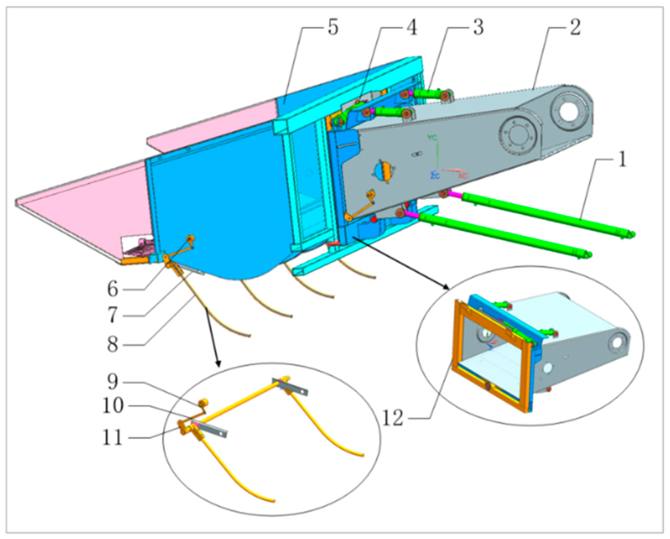
Figure 2.
Kinematic modeling of the regulating mechanism in the vertical direction.
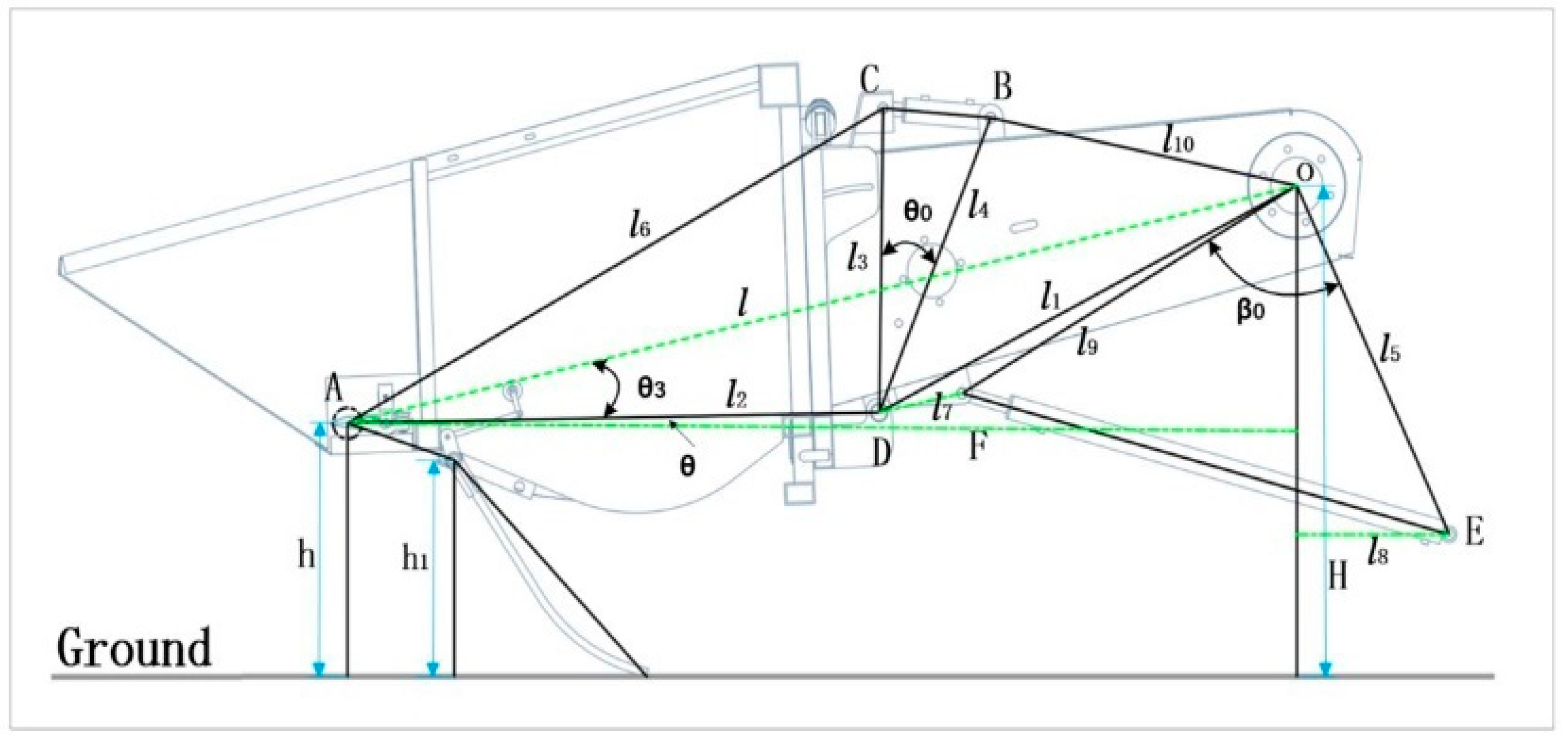
Figure 3.
Kinematic modeling of the regulating mechanism in the horizontal direction.
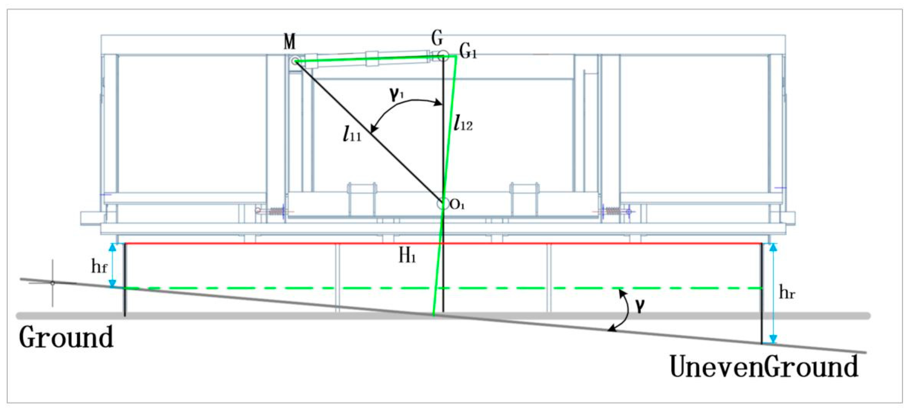
Figure 4.
(a) Kinematic modeling of affine mechanisms; (b) Computational model for conversion of affine angles to sensor acquisition angles.
Figure 4.
(a) Kinematic modeling of affine mechanisms; (b) Computational model for conversion of affine angles to sensor acquisition angles.
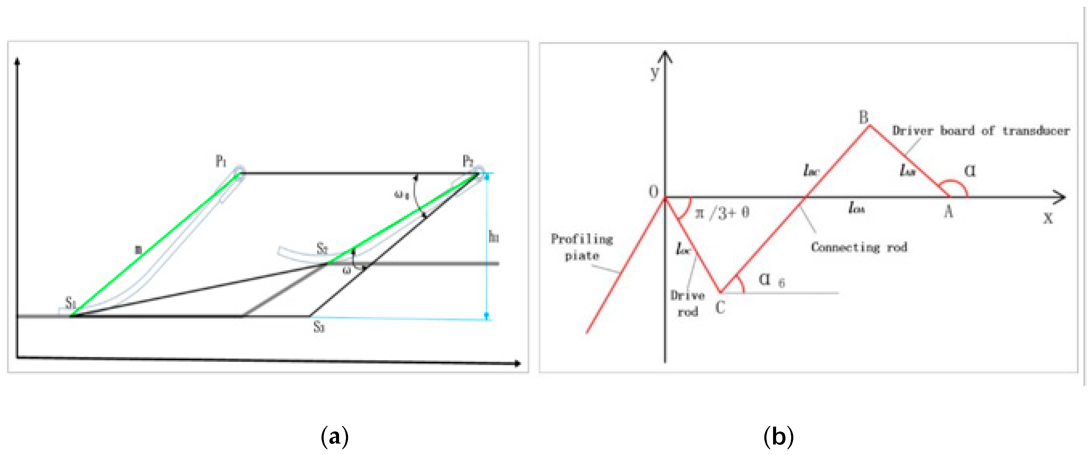
Figure 5.
Leveling strategy for profiling grain cutting table control system.
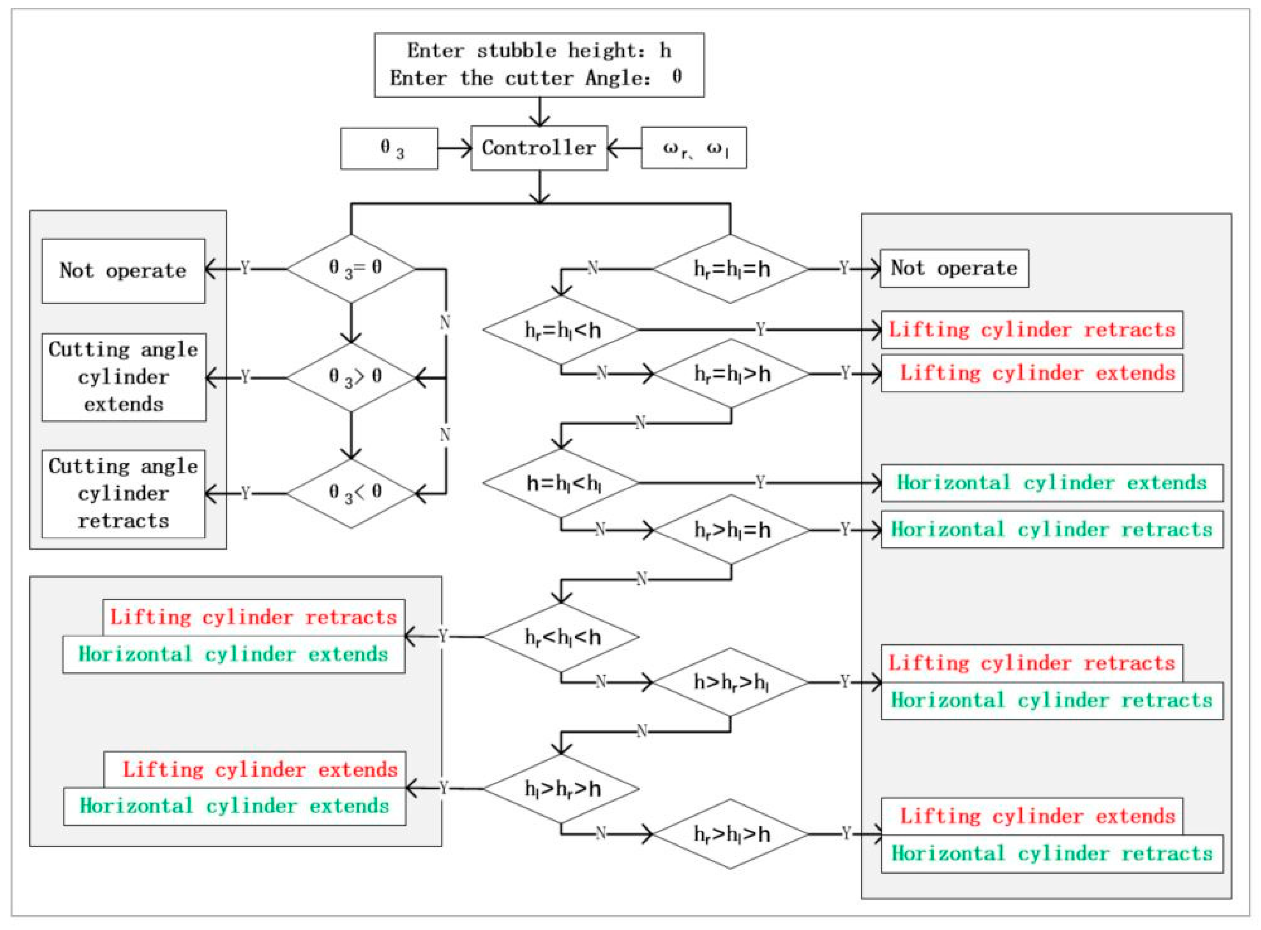
Figure 6.
Schematic diagram of the hydraulic system of the imitation row grain cutting table. 1. Double-acting hydraulic cylinders; 2. One-way speed control valves; 3. Check valves, 4. Safety valves; 5. Switching valves; 6. Three-position four-way solenoid operated proportional valves; 7. Two-position three-way solenoid operated proportional valves; 8. Solenoid relief valves; 9. Accumulators, 10.Decompression valves; 11. Buffer valves; 12. Hydraulic pumps; 13. Oil tanks;
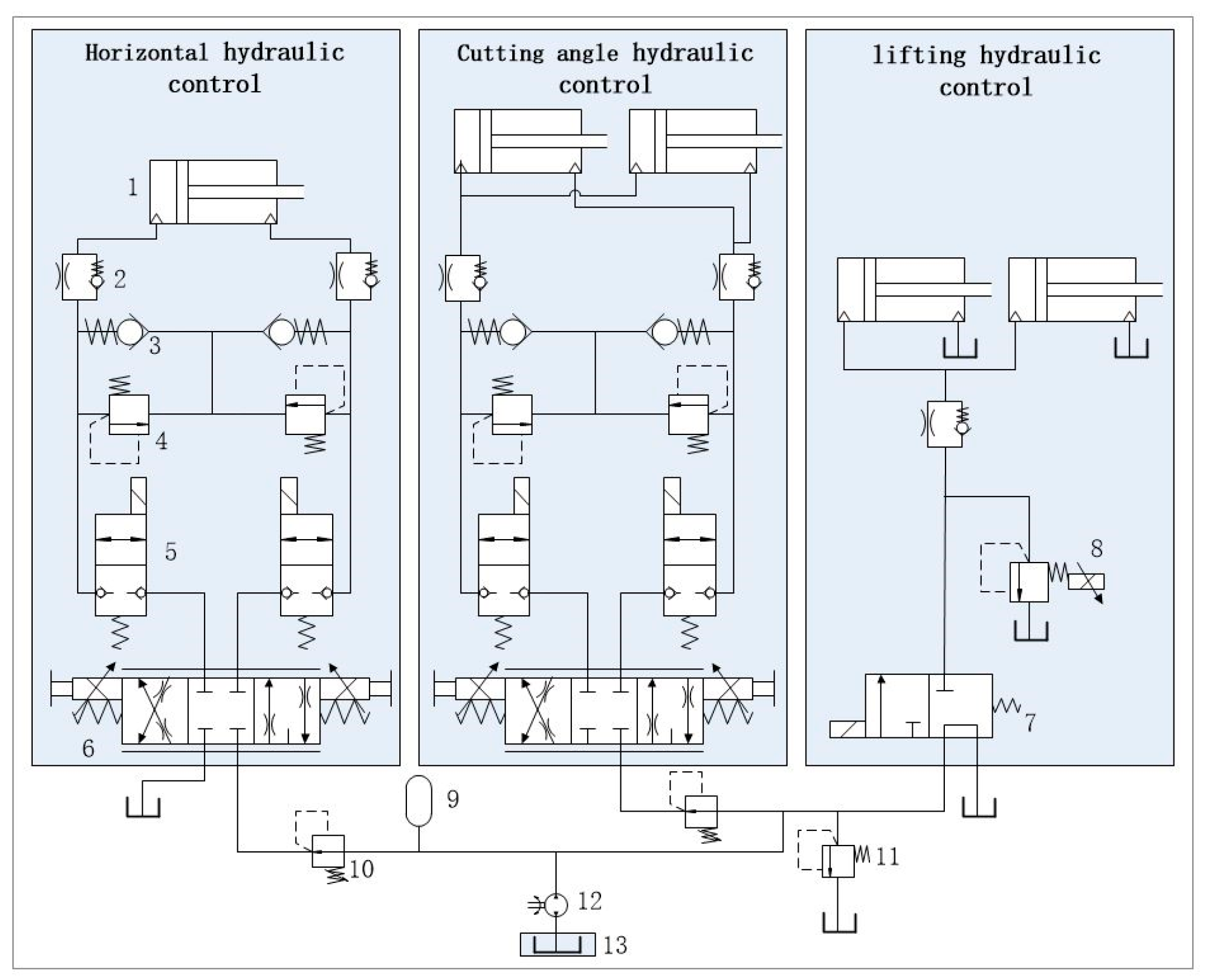
Figure 7.
Joint Simulation Modeling of Hydraulic Systems. Hydraulic module and 2D Mechanicaal module for joint simulation to analyze the cutting table lifting ram cylinder, horizontal oscillating ram cylinder, and front and rear floating ram cylinder motion patterns, and evaluate the dynamic
Figure 7.
Joint Simulation Modeling of Hydraulic Systems. Hydraulic module and 2D Mechanicaal module for joint simulation to analyze the cutting table lifting ram cylinder, horizontal oscillating ram cylinder, and front and rear floating ram cylinder motion patterns, and evaluate the dynamic
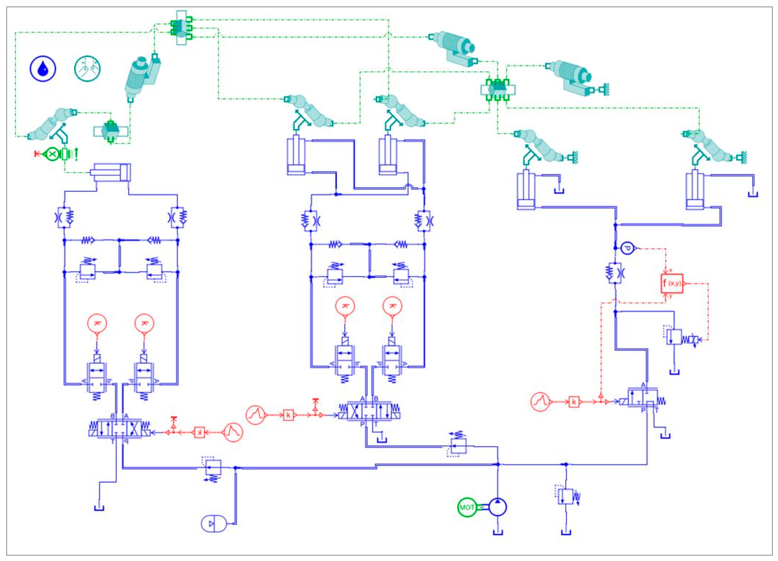
Figure 8.
Lifting hydraulic cylinder simulation analysis results.
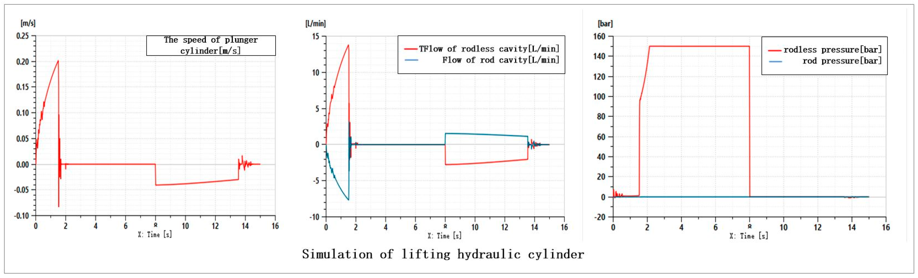
Figure 9.
Cutting angle hydraulic cylinder simulation analysis results.
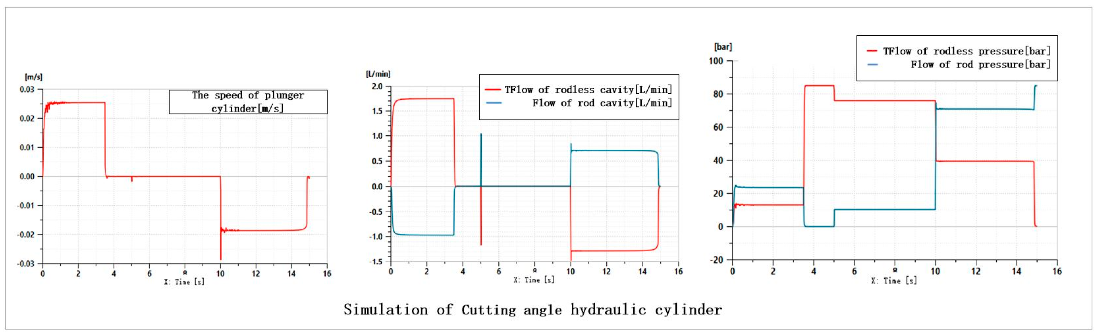
Figure 10.
Horizontal hydraulic cylinder simulation analysis results.
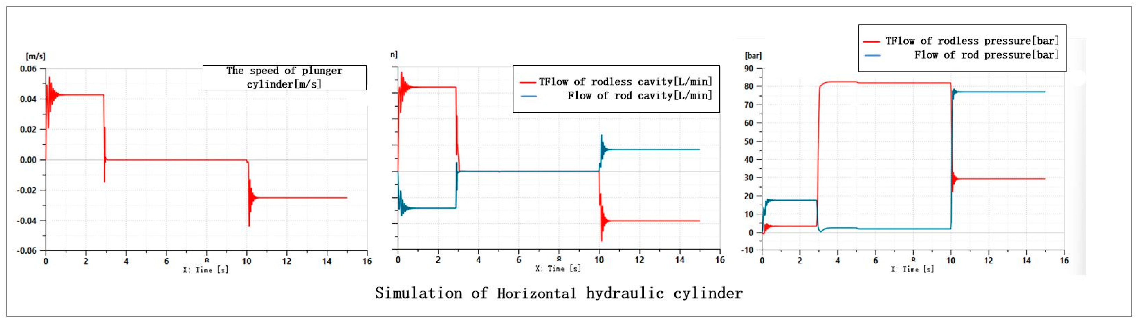
Figure 11.
(a) Prototype field test and data collection.
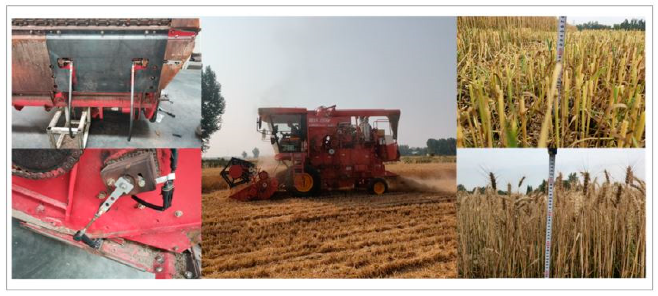
Figure 12.
Static test results for profiling cutter elevation statistics.
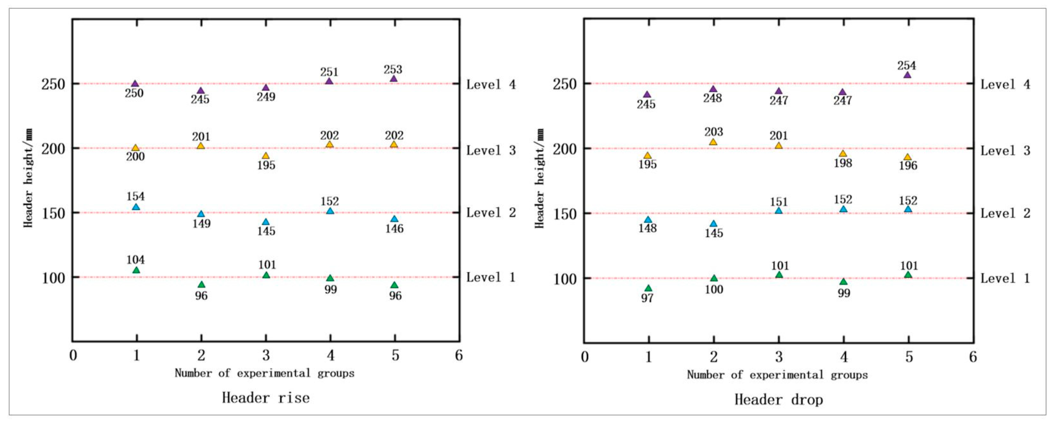
Figure 13.
Statistical results of field trial data.
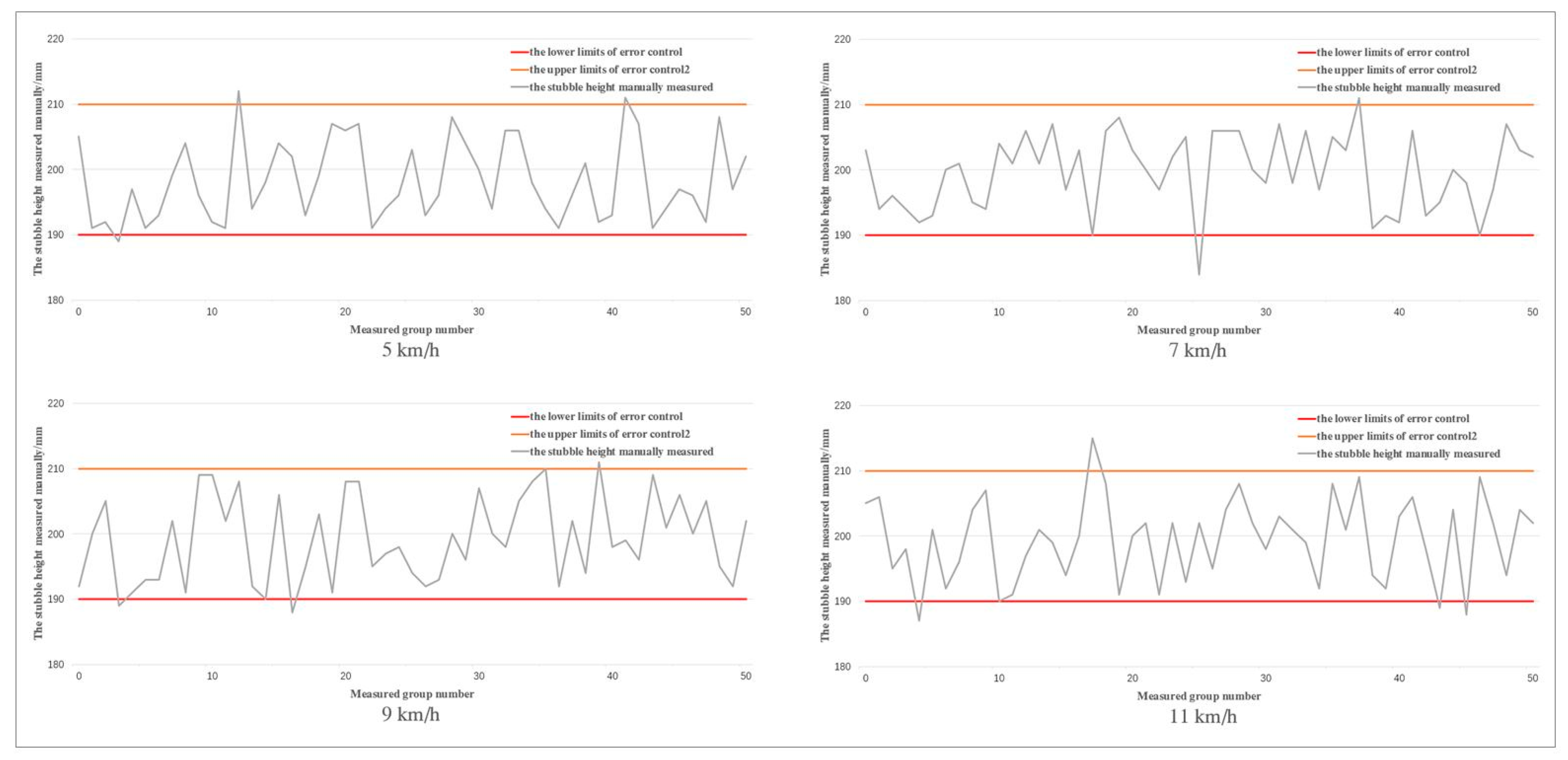

Table 1.
Analysis of static test results for profiling cutter elevation.
| State | Header height(mm) | Max AEV(mm) | Min AEV(mm) | MAEV(mm) | MRE(%) | ART(%) |
|---|---|---|---|---|---|---|
| Up | 100 | 4 | 1 | 2.5 | 2.83 | 0.52 |
| 150 | 5 | 1 | 3 | 2.15 | 0.45 | |
| 200 | 5 | 0 | 2.5 | 1.00 | 0.77 | |
| 250 | 5 | 0 | 2.5 | 0.80 | 0.60 | |
| Down | 100 | 3 | 0 | 1.5 | 1.22 | 0.70 |
| 150 | 4 | 1 | 2.5 | 1.62 | 0.84 | |
| 200 | 5 | 1 | 3 | 1.51 | 0.65 | |
| 250 | 5 | 2 | 3.5 | 1.37 | 0.72 |
Table 2.
Analysis of static test results for profiling cutter slopes
| State | Header height(mm) | Max AEV(mm) | Min AEV(mm) | MAEV(mm) | MRE(%) | ART(%) |
|---|---|---|---|---|---|---|
| Left deflection |
100 | 4 | 2 | 2.6 | 2.58 | 0.62 |
| 150 | 5 | 0 | 2.4 | 1.65 | 0.55 | |
| 200 | 4 | 2 | 2.8 | 1.39 | 0.87 | |
| 250 | 5 | 0 | 2 | 0.81 | 0.56 | |
| Right deflection |
100 | 4 | 0 | 2 | 2.04 | 0.63 |
| 150 | 4 | 1 | 2.6 | 1.76 | 0.78 | |
| 200 | 4 | 1 | 3 | 1.51 | 0.71 | |
| 250 | 5 | 1 | 2.6 | 1.03 | 0.82 |
Table 3.
Analysis of statistical results of field trial data.
| NO. | Vehicle travel speed(km/h) | Stubbleheight L(mm) | C.V(%) | τ(%) | SSR(%) |
|---|---|---|---|---|---|
| 1 | 5 | 198.22 | 3.2 | 94 | 0 |
| 2 | 7 | 199.68 | 3.0 | 96 | 0 |
| 3 | 9 | 199.14 | 6.1 | 94 | 0 |
| 4 | 11 | 199.40 | 5.8 | 92 | 0 |
Disclaimer/Publisher’s Note: The statements, opinions and data contained in all publications are solely those of the individual author(s) and contributor(s) and not of MDPI and/or the editor(s). MDPI and/or the editor(s) disclaim responsibility for any injury to people or property resulting from any ideas, methods, instructions or products referred to in the content. |
© 2025 by the authors. Licensee MDPI, Basel, Switzerland. This article is an open access article distributed under the terms and conditions of the Creative Commons Attribution (CC BY) license (http://creativecommons.org/licenses/by/4.0/).
Copyright: This open access article is published under a Creative Commons CC BY 4.0 license, which permit the free download, distribution, and reuse, provided that the author and preprint are cited in any reuse.


