Submitted:
16 January 2025
Posted:
17 January 2025
You are already at the latest version
Abstract
This work presents a novel design for an asymmetric loop-terminated Mach-Zehnder interferometer (a-LT-MZI) based on a silicon-on-insulator (SOI) platform, tailored for refractive index (RI) sensing applications. A significant advantage of incorporating the Sagnac loop into the MZI configuration is its ability to reduce the interferometer’s effective length by half, offering a more compact design. This makes it ideal for integration into miniaturized optical devices, enabling space-efficient configurations without compromising precision or performance. The proposed device, featuring a pathlength difference (∆L) of 24.35 µm demonstrates a sensitivity of 261 nm/RIU, which is further enhanced to 510 nm/RIU by incorporating a subwavelength (SWG) waveguide in the asymmetric sensing arm. This modification boosts light-matter interaction, resulting in a larger shift in the interference fringes and significantly improving the sensor's performance.
Keywords:
Loop terminated Mach-Zehnder Interferometer
; Silicon-on-insulator
; Sagnac loop
; subwavelength grating waveguide
1. Introduction
The Mach-Zehnder interferometer (MZI) operates by splitting a coherent light beam into two paths using a beam splitter[1]. These paths are then recombined at a second beam splitter, producing interference based on the relative phase difference between the two paths[2,3]. This phase difference can be influenced by changes in the optical path length, caused by variations in temperature, pressure, refractive index, or mechanical stress in the environment[4]. Due to its high sensitivity to these changes, the MZI is widely employed in sensing applications, such as chemical detection, strain measurement, temperature, and biosensing, by monitoring the interference pattern to detect subtle environmental variations[5,6,7].
The Sagnac loop is a vital component in modern optical systems, particularly in the loop-terminated Mach–Zehnder interferometer (LT-MZI), where it significantly enhances both performance and functionality[8,9]. A key advantage of the Sagnac loop is its ability to reduce the interferometer's effective length by half[4]. This compact design is highly advantageous for integration into miniaturized optical devices, enabling space-efficient configurations without compromising precision or performance. Furthermore, the loop enhances the interferometer’s phase sensitivity by increasing the effective optical path length through light recirculation. This amplification of interference effects permits the recognition of minute variations in the target parameters with exceptional accuracy. The Sagnac loop also offers superior common-mode rejection, a critical feature for eliminating noise and mitigating the impact of environmental disturbances[10]. By ensuring that common perturbations affecting both arms of the interferometer do not influence the interference pattern, the Sagnac loop provides highly stable and reliable measurements[9]. These combined attributes make the Sagnac loop indispensable in advanced interferometric sensors, such as those used for high-precision refractive index measurements and other sophisticated sensing applications[11,12].
In this work, an innovative a-LT-MZI structure on a silicon-on-insulator (SOI) platform is suggested for refractive index sensing applications. To further amplify the device’s sensitivity, an advanced asymmetric subwavelength grating loop-terminated Mach-Zehnder interferometer (a-SWG-LT-MZI) configuration is introduced. In this enhanced configuration, the sensing arm, originally made of a ridge waveguide (WG), is replaced with an SWG structure, which substantially enhances light-matter interaction. This modification enables more effective interaction between the guided light and the surrounding medium, resulting in almost twofold enhancement in sensitivity compared to a-LT-MZI structure based on a ridge WG. This approach not only improves the device's performance but also underscores its potential for high-precision and miniaturized sensing applications.
2. Sensor design and numerical model
In this work, an a-LT-MZI structure on a silicon-on-insulator (SOI) platform is proposed for RI sensing applications. The schematic of the device is shown in Figure 1, and the geometric parameters of the device are elaborated in Table 1. The WGs are composed of silicon (Si), offering high RI contrast and excellent optical confinement. The device incorporates a silicon dioxide (SiO₂) upper cladding layer for enhanced protection and stability, with a strategically etched sensing window on the sensing arm. This window enables direct interaction between the guided optical mode and the surrounding environment, facilitating efficient analyte detection. This design enables direct interaction between the propagating optical mode and the introduced analytes, leading to a change in the effective refractive index (neff). This change causes a shift in the interference pattern, which forms the basis for precise RI measurements.
The Finite Element Method (FEM), implemented through COMSOL Multiphysics, provides a robust and precise computational approach for analyzing the transmission spectra and field distributions of a-LT-MZI structures. It enables the modeling of the complex geometry and material properties of the LT-MZI, accounting for variations in WG dimensions, refractive indices, and asymmetry. The material library in COMSOL provides a comprehensive database of material properties for accurate simulations. In this study, the refractive indices of Si and SiO2 were obtained directly from the COMSOL material library to ensure precision in optical modeling. By solving Maxwell's equations in the spatial domain, FEM facilitates the computation of optical field distributions across the structure, offering detailed insights into mode coupling, interference effects, and localized field intensities. The transmission spectrum is analyzed over a wavelength range of 1520 nm to 1565 nm, providing a sufficiently broad span to capture multiple interference dips of the device with high precision. This range ensures a comprehensive assessment of the device's spectral response and enables detailed characterization of its interference behavior.
3. Device Optimization
It is crucial to optimize the device geometry before utilizing it for sensing applications. In the initial step, the gap (g) between the WGs in the directional coupler (DC) with a length (LDC) of 1 µm is optimized to achieve optimal performance. The spacing between the WGs in a DC is critical as it directly impacts the power coupling efficiency between the WGs. This gap determines the strength of the evanescent field interaction, which governs how much optical power transfers from one WG to the other. If the gap is too large, the evanescent fields do not overlap significantly, leading to weak coupling and reduced power transfer. Conversely, if the gap is too small, excessive coupling can occur, which may result in unintended power distribution or higher losses due to fabrication imperfections. Optimizing this gap ensures precise control of the coupling coefficient, enabling the coupler to achieve the desired performance in terms of splitting ratio or power distribution. This optimization is especially crucial in PICs, where tight tolerances and efficient energy management are essential for device functionality. The transmission spectrum of LT-MZI structure is plotted for different values of g ranges between 100 nm and 300 nm as shown in Figure 2 (a-e). For g ranging from 100 nm to 200 nm, the interference dips exhibit a narrow linewidth (FWHM) and maintain a high extinction ratio (ER) exceeding 15 dB (Figure 2 (a-c)). However, as g increases to 250 nm, the FWHM of the interference dips broadens, likely due to the overlap of adjacent dips, as illustrated in Figure 2 (d). When g reaches 300 nm, the interference dips become significantly wider, accompanied by a substantial reduction in the ER to approximately 7.9 dB, as shown in Figure 2 (e).
The free spectral Range (FSR) of an a-LT-MZI decreases as the path length difference (ΔL) between the sensing arm and the reference arm increases due to the inverse relationship between FSR and the optical path length difference[13]. In the wavelength domain, the FSR is expressed as:
where λ is the operational wavelength and ng is the group index. Shamy et al. calculated the ng of an SOI WG over a broad wavelength range between 1.5 µm and 1.6 µm, finding it to be approximately 4.2[11]. Overall, as the path length difference increases, the phase difference between the two arms accumulates more rapidly, causing interference fringes to appear closer together in both frequency and wavelength domains, thereby decreasing the FSR[14]. The transmission spectrum of the LT-MZI structure is presented for a wavelength range of 1520 nm to 1565 nm, corresponding to Lsens of 43.55 µm, 63.55 µm, 83.55 µm, and 103.55 µm, as depicted in Figure 3(a–d). The FSR of the device decreases from 11.5 nm to 4 nm as ΔL increases from 24.35 µm to 84.35 µm. The analytical predictions derived from Eq. (1) align closely with the numerical results, as illustrated in Figure 3(e).
In the subsequent analysis, the impact of the WG width (w) on the interference pattern is evaluated over the wavelength range of 1520–1565 nm, as illustrated in Figure 4 (a–h). Notably, for w=350 nm and 360 nm, significant distortion of the interference fringes is observed, accompanied by an increase in the FSR, as shown in Figure 4 (a, b). Such distorted interference patterns are undesirable for sensing applications, as they compromise the consistency and precision required for reliable measurements. The distortion of interference fringes and the widening of FSR can be attributed to the higher-order dispersion effects, leading to phase mismatches between interfering modes and disrupting the coherence of the interference fringes. This emphasizes the need for optimizing WG dimensions to maintain well-defined and stable interference patterns suitable for high-precision sensing systems. For w ranging from 370 nm to 420 nm, the interference patterns are notably well-defined, leading to the appearance of sharp and narrow dips in the transmission spectrum (Figure 4 (c-h)). This enhanced clarity and precision in the interference fringes indicates improved phase coherence and minimal distortion, making this range of WG widths highly suitable for applications requiring accurate and sensitive spectral measurements.
Figure 5 (a, b) depicts the normalized H-field distribution for the optimized LT-MZI structure, highlighting the phenomena of constructive and destructive interference at wavelengths of 1540.5 nm and 1534.5 nm, respectively. For both scenarios, the RI of the medium surrounding the sensing arm is consistently maintained at 1.33, highlighting the structure's sensitivity to wavelength-specific interference patterns.
4. RI Sensing Application
RI sensing using the MZI structures has emerged as a highly sensitive and versatile approach for detecting changes in the optical properties of a medium[15,16]. When the RI of the medium changes—due to the presence of a target substance or a biochemical interaction, the LT-MZI structure detects alterations in optical signals such as destructive interference wavelength[7]. The sensitivity of the device is calculated by utilizing eq (2). This capability is particularly relevant for biosensing applications, where biological interactions like antibody-antigen binding, enzyme-substrate reactions, or nucleic acid hybridization can induce minute changes in the local refractive index.
Where λ is the destructive interference wavelength and n is the medium refractive index.
4.1. Design of a-SWG-LT-MZI
Subwavelength grating (SWG) WGs offer significant advantages over standard ridge WGs for sensing applications due to their enhanced light-matter interaction capabilities and increased design flexibility[17,18]. The periodic structure of SWG WGs allows for precise control of the effective refractive index, enabling the engineering of high-sensitivity photonic devices. Their ability to confine light in regions with high overlap between the optical field and the analyte enhances the interaction, improving the sensitivity of sensors[19]. Additionally, SWG WGs can support engineered dispersion and polarization control, which are critical in optimizing the performance of many sensing systems[20]. Compared to standard ridge WGs, they also facilitate the integration of advanced functionalities, such as slow-light effects and tailored modal profiles, further improving detection capabilities and enabling compact, highly efficient sensing platforms[20,21]. Recently, several highly sensitive photonic devices based on SWG WGs have been proposed for different sensing applications[22,23,24,25].
Initially, the geometry of the SWG WG is optimized to achieve optimal transmission, ensuring its seamless integration into the device for enhanced performance. The transmission spectrum of an SWG WG is plotted for different duty cycles (D) in the wavelength range of 1520 nm to 1565 nm as shown in Figure 6 (a). D is calculated by utilizing equation (3).
Where a and b are the length of the high index material (Si) and the length of the low index material (air), respectively. To suppress higher-order diffraction modes, Λ< λ/neff. This ensures that only the fundamental mode propagates, enabling the WG to effectively behave as a homogeneous medium[26]. Within the subwavelength condition (D=0.5 to 0.75), the structure suppresses Bragg reflections, allowing the SWG WG to operate similarly to a traditional WG with continuous material properties. However, when D approaches 0.78, Bragg reflections emerge in the transmission spectrum, obstructing the propagating mode and disrupting efficient WG operation. The normalized H-field distribution in the SWG WG is presented for D=0.78 and D=0.71 at operational wavelengths of 1525 nm and 1550 nm, respectively, as illustrated in Figure 6(b). It is evident that in case (I), the field fails to propagate to the end of the WG due to the presence of Bragg reflections, which disrupt the transmission. In contrast, in case (II), the field propagates seamlessly as a single Bloch mode, effectively emulating the behavior of a continuous mode in a homogeneous medium.
To validate the superiority of the SWG WG over the standard ridge WG, the sensitivity of both WG structures is evaluated by monitoring the variation in transmission power as a function of changes in the RI of the surrounding medium (Figure 6 c,d). This sensitivity is quantitatively assessed using the calculation provided in Eq. (4). This comparison highlights the enhanced performance of the SWG WG in terms of its responsiveness to RI variations in the ambient medium.
The sensitivity of the SWG WG is approximately 5.4 dB/RIU, a remarkable improvement compared to the 1.9 dB/RIU sensitivity offered by a standard ridge WG. This substantial enhancement underscores the superior performance of the SWG WG in RI sensing. Furthermore, this analysis highlights that integrating the SWG WG into the a-LT-MZI structure will not only leverage its high sensitivity but also significantly elevate the overall detection efficiency of the system, making it a highly promising approach for advanced sensing applications.
Building on the optimized geometry of the SWG WG, the straight segment of the sensing arm in the a-LT-MZI structure is replaced with a SWG WG featuring a duty cycle of D=0.67 as depicted in Figure 7. All other geometric parameters are maintained in alignment with the optimized values established in the preceding section, ensuring consistency in the design.
Figure 8 presents the normalized H-field distribution in the a-LT-MZI structure at an operational wavelength of 1535.5 nm, with the sensing arm surrounded by a medium of RI=1.33. The inset provides a detailed view of the field distribution in key regions: the loop segment (top-right), the SWG segment (top-left), and the DC. In DC, destructive interference occurs, effectively canceling the optical power and manifesting as an interference dip in the transmission spectrum. This detailed visualization highlights the critical role of each segment in the overall performance of the structure.
4.2. Sensing Performance of a-LT-MZI and SWG-a-LT-MZI Structures
The sensing performance of the a-LT-MZI and SWG-a-LT-MZI structures having ΔL=24.35 µm is analyzed by varying the RI of the medium covering their sensing arms. The transmission spectra, presented in Figure 9(a) and 9(b) for the a-LT-MZI and SWG-a-LT-MZI, respectively, demonstrate a pronounced redshift in the resonance wavelength as the RI increases from 1.33 to 1.36. This trend is further quantified in Figure 9(c), which plots the resonance wavelength against the refractive index, highlighting a significantly steeper slope for the SWG-a-LT-MZI structure compared to the a-LT-MZI.
The sensitivity of the SWG-a-LT-MZI structure, defined as the ratio of the change in resonance wavelength to the change in ambient refractive index (S=Δλ/Δn), is approximately 510 nm/RIU—nearly double that of the a-LT-MZI structure, which exhibits a sensitivity of around 210 nm/RIU. This marked improvement underscores the SWG-a-LT-MZI's superior capability for detecting minute RI variations, making it highly suitable for advanced sensing applications.
5. Conclusions
In this study, a high-sensitivity design for a silicon-on-insulator (SOI)-based asymmetric loop-terminated Mach-Zehnder Interferometer (a-LT-MZI) was presented and analyzed. By integrating a subwavelength grating (SWG) WG into the a-LT-MZI structure, significant enhancements in sensitivity were achieved compared to a-LT-MZI. The SWG structure not only optimizes the effective RI modulation but also facilitates stronger interaction between the guided mode and the surrounding medium, resulting in a more pronounced phase shift for small RI changes. The analysis is conducted by employing the finite element method via COMSOL Multiphysics software. The sensitivity of a-LT-MZI and SWG-a-LT-MZI with ∆L=24.35 µm is estimated at 261 nm/RIU and 510 nm/RIU, respectively. This enhanced performance highlights the potential of the SWG-a-LT-MZI as a promising candidate for high-precision sensing applications, such as biochemical detection and environmental monitoring.
Funding
This research received no external funding.
Institutional Review Board Statement
Not applicable.
Informed Consent Statement
Not applicable.
Data Availability Statement
The data will be provided at a reasonable request to the author.
Acknowledgments
The author acknowledges the constant support of Warsaw University of Technology in the completion of this work. .
Conflicts of Interest
The author declares no conflicts of interest.
References
- Levy, U.; Desiatov, B.; Goykhman, I.; Nachmias, T.; Ohayon, A.; Meltzer, S.E. Design, Fabrication, and Characterization of Circular Dammann Gratings Based on Grayscale Lithography. Opt. Lett. 2010, 35, 880–882. [Google Scholar] [CrossRef]
- Li, G.; Li, T.; Liu, Y.; Zheng, Y. A New Mach–Zehnder Interference Temperature Measuring Sensor Based on Silica-Based Chip. Sci. Rep. 2024, 14, 8657. [Google Scholar] [CrossRef] [PubMed]
- Ouyang, B.; Li, Y.; Kruidhof, M.; Horsten, R.; Dongen, K.W.A. van; Caro, J. On-Chip Silicon Mach–Zehnder Interferometer Sensor for Ultrasound Detection. Opt. Lett. 2019, 44, 1928–1931. [Google Scholar] [CrossRef] [PubMed]
- Butt, M.A. Loop-Terminated Mach-Zehnder Interferometer Integrated with Functional Polymer for CO2 Gas Sensing 2024.
- Zhao, C.; Xu, L.; Liu, L. Ultrahigh Sensitivity Mach−Zehnder Interferometer Sensor Based on a Weak One-Dimensional Field Confinement Silica Waveguide. Sensors 2021, 21, 6600. [Google Scholar] [CrossRef] [PubMed]
- Ding, Z.; Dai, D.; Shi, Y. Ultra-Sensitive Silicon Temperature Sensor Based on Cascaded Mach–Zehnder Interferometers. Opt. Lett. 2021, 46, 2787–2790. [Google Scholar] [CrossRef] [PubMed]
- Wu, Y.; Zhou, Y.; Pan, J.; Huang, T.; Jin, S. Design of Highly Sensitive Refractive Index Sensor Based on Silicon Photonic Mach–Zehnder Interferometer. Opt. Commun. 2023, 534, 129288. [Google Scholar] [CrossRef]
- Soref, R.A.; Leonardis, F.D.; Passaro, V.M.N. Multiple-Sagnac-Loop Mach–Zehnder Interferometer for Wavelength Interleaving, Thermo-Optical Switching and Matched Filteri. J. Light. Technol. 2018, 36, 5254–5262. [Google Scholar] [CrossRef]
- El Shamy, R.S.; Swillam, M.A.; ElRayany, M.M.; Sultan, A.; Li, X. Compact Gas Sensor Using Silicon-on-Insulator Loop-Terminated Mach–Zehnder Interferometer. Photonics 2022, 9, 8. [Google Scholar] [CrossRef]
- Sagnac Interference in Integrated Photonics | Applied Physics Reviews | AIP Publishing Available online:. Available online: https://pubs.aip.org/aip/apr/article/10/1/011309/2881196/Sagnac-interference-in-integrated-photonics (accessed on 7 May 2024).
- El Shamy, R.S.; Afifi, A.E.; Badr, M.M.; Swillam, M.A. Modelling, Characterization, and Applications of Silicon on Insulator Loop Terminated Asymmetric Mach Zehnder Interferometer. Sci. Rep. 2022, 12, 3598. [Google Scholar] [CrossRef]
- Kim, D.-H.; Kang, J.U. Sagnac Loop Interferometer Based on Polarization Maintaining Photonic Crystal Fiber with Reduced Temperature Sensitivity. Opt. Express 2004, 12, 4490–4495. [Google Scholar] [CrossRef]
- Han, M.; Li, X.; Zhang, S.; Liu, J.; Feng, Y.; Shang, C.; Han, H. Wavelength Switchable, Free Spectral Range Accurately Control Single-Pass Mach-Zehnder Interferometer Comb Filter. In Proceedings of the 2017 16th International Conference on Optical Communications and Networks (ICOCN); August 2017; pp. 1–3. [Google Scholar]
- Eftimov, T.; Arapova, A.; Janik, M.; Bock, W.J. Broad Range Bimodal Microcavity In-Line Mach-Zehnder Interferometers. Opt. Laser Technol. 2022, 145, 107503. [Google Scholar] [CrossRef]
- Doughan, I.; Oyemakinwa, K.; Ovaskainen, O.; Roussey, M. Strip-Loaded Mach–Zehnder Interferometer for Absolute Refractive Index Sensing. Sci. Rep. 2024, 14, 3064. [Google Scholar] [CrossRef]
- Wu, D.; Zhu, T.; Deng, M.; Duan, D.-W.; Shi, L.-L.; Yao, J.; Rao, Y.-J. Refractive Index Sensing Based on Mach–Zehnder Interferometer Formed by Three Cascaded Single-Mode Fiber Tapers. Appl. Opt. 2011, 50, 1548–1553. [Google Scholar] [CrossRef] [PubMed]
- Butt, M.A.; Tyszkiewicz, C.; Wojtasik, K.; Karasiński, P.; Kaźmierczak, A.; Piramidowicz, R. Subwavelength Grating Waveguide Structures Proposed on the Low-Cost Silica–Titania Platform for Optical Filtering and Refractive Index Sensing Applications. Int. J. Mol. Sci. 2022, 23, 6614. [Google Scholar] [CrossRef] [PubMed]
- Butt, M.A.; Tyszkiewicz, C.; Wojtasik, K.; Karasiński, P.; Kaźmierczak, A.; Piramidowicz, R. Subwavelength Grating Waveguide Structures Proposed on the Low-Cost Silica–Titania Platform for Optical Filtering and Refractive Index Sensing Applications. Int. J. Mol. Sci. 2022, 23, 6614. [Google Scholar] [CrossRef]
- S. N Khonina; N.L Kazanskiy; M.A. Butt Spectral Characteristics of Broad Band-Rejection Filter Based on Bragg Grating, One-Dimensional Photonic Crystal, and Subwavelength Grating Waveguide. Phys. Scr. 2021, 96, 055505. [Google Scholar] [CrossRef]
- Kazanskiy, N.L.; Butt, M.A.; Khonina, S.N. Silicon Photonic Devices Realized on Refractive Index Engineered Subwavelength Grating Waveguides-A Review. Opt. Laser Technol. 2021, 138, 106863. [Google Scholar] [CrossRef]
- Odeh, M.; Twayana, K.; Sloyan, K.; Villegas, J.E.; Chandran, S.; Dahlem, M.S. Mode Sensitivity Analysis of Subwavelength Grating Slot Waveguides. IEEE Photonics J. 2019, 11, 1–10. [Google Scholar] [CrossRef]
- Ariannejad, M.M.; Akbari, E.; Hanafi, E. Silicon Sub-Wavelength Grating Resonator Structures for Gas Sensor. Superlattices Microstruct. 2020, 142, 106506. [Google Scholar] [CrossRef]
- Sun, Y.; Hu, G.; Cui, Y. Subwavelength Grating Waveguide Racetrack-Based Refractive Index Sensor with Improved Figure of Merit. Appl. Opt. 2020, 59, 10613–10617. [Google Scholar] [CrossRef] [PubMed]
- Bickford, J.R.; Cho, P.S.; Farrell, M.E.; Holthoff, E.L.; Pellegrino, P.M. The Investigation of Subwavelength Grating Waveguides for Photonic Integrated Circuit Based Sensor Applications. IEEE J. Sel. Top. Quantum Electron. 2019, 25, 1–10. [Google Scholar] [CrossRef]
- Wangüemert-Pérez, J.G.; Cheben, P.; Ortega-Moñux, A.; Alonso-Ramos, C.; Pérez-Galacho, D.; Halir, R.; Molina-Fernández, I.; Xu, D.-X.; Schmid, J.H. Evanescent Field Waveguide Sensing with Subwavelength Grating Structures in Silicon-on-Insulator. Opt. Lett. 2014, 39, 4442–4445. [Google Scholar] [CrossRef]
- Kazanskiy, N.L.; Khonina, S.N.; Butt, M.A. Subwavelength Grating Double Slot Waveguide Racetrack Ring Resonator for Refractive Index Sensing Application. Sensors 2020, 20, 3416. [Google Scholar] [CrossRef] [PubMed]
Figure 1.
2D scheme of a-LT-MZI structure. The inset shows the cross-sectional view of the reference arm section (right) and sensing arm section (left).
Figure 1.
2D scheme of a-LT-MZI structure. The inset shows the cross-sectional view of the reference arm section (right) and sensing arm section (left).
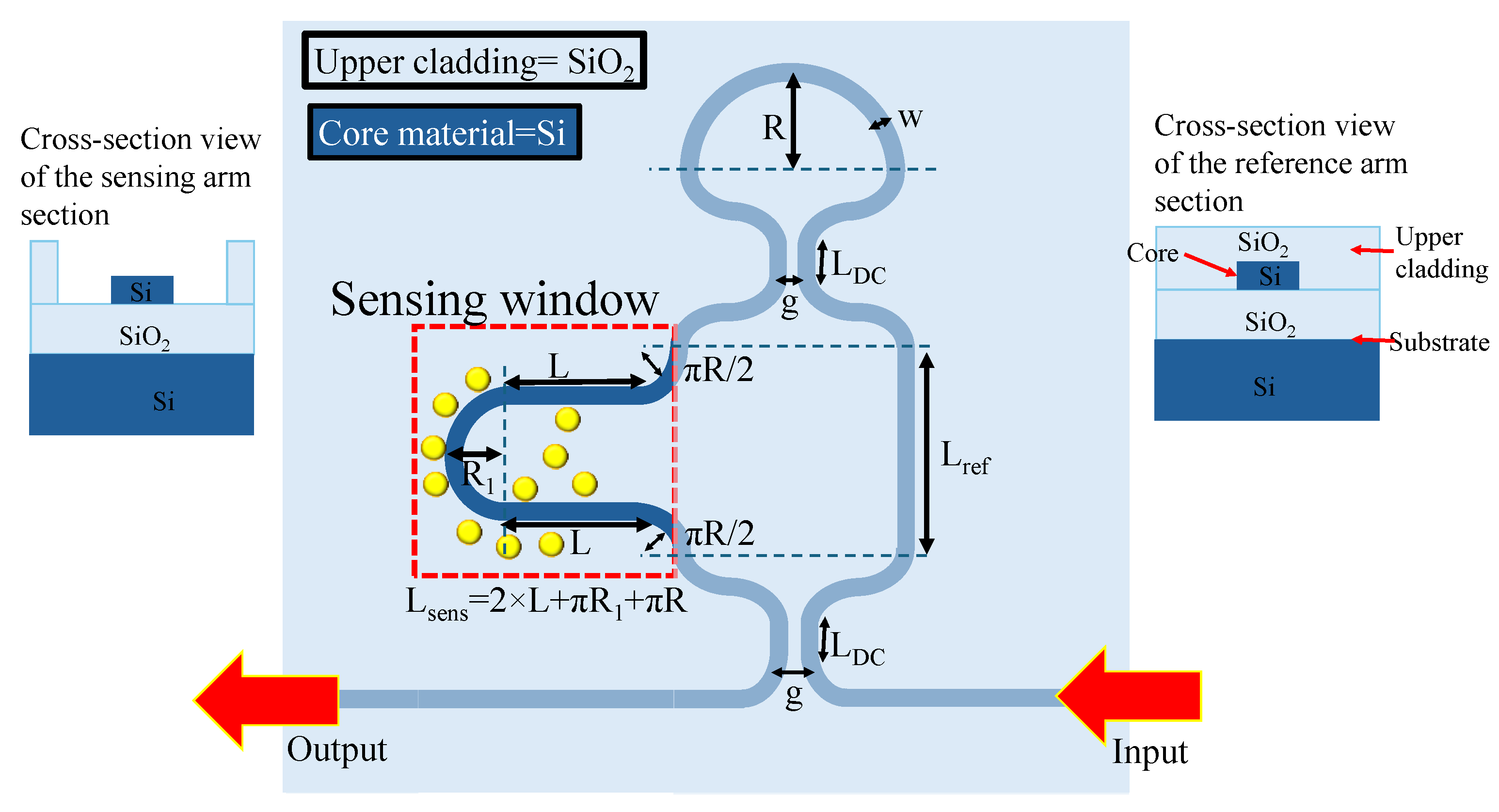
Figure 2.
Transmission spectrum of a-LT-MZI structure for different values of g, (a) 100 nm, (b) 150 nm, (c) 200 nm, (d) 250 nm, and (e) 300 nm. The remaining geometric parameters of the device are kept constant: R=5 µm, R1=2.5 µm, w=400 nm, LDC=1 µm, Lsens=43.55 µm, and Lref=19.2 µm.
Figure 2.
Transmission spectrum of a-LT-MZI structure for different values of g, (a) 100 nm, (b) 150 nm, (c) 200 nm, (d) 250 nm, and (e) 300 nm. The remaining geometric parameters of the device are kept constant: R=5 µm, R1=2.5 µm, w=400 nm, LDC=1 µm, Lsens=43.55 µm, and Lref=19.2 µm.
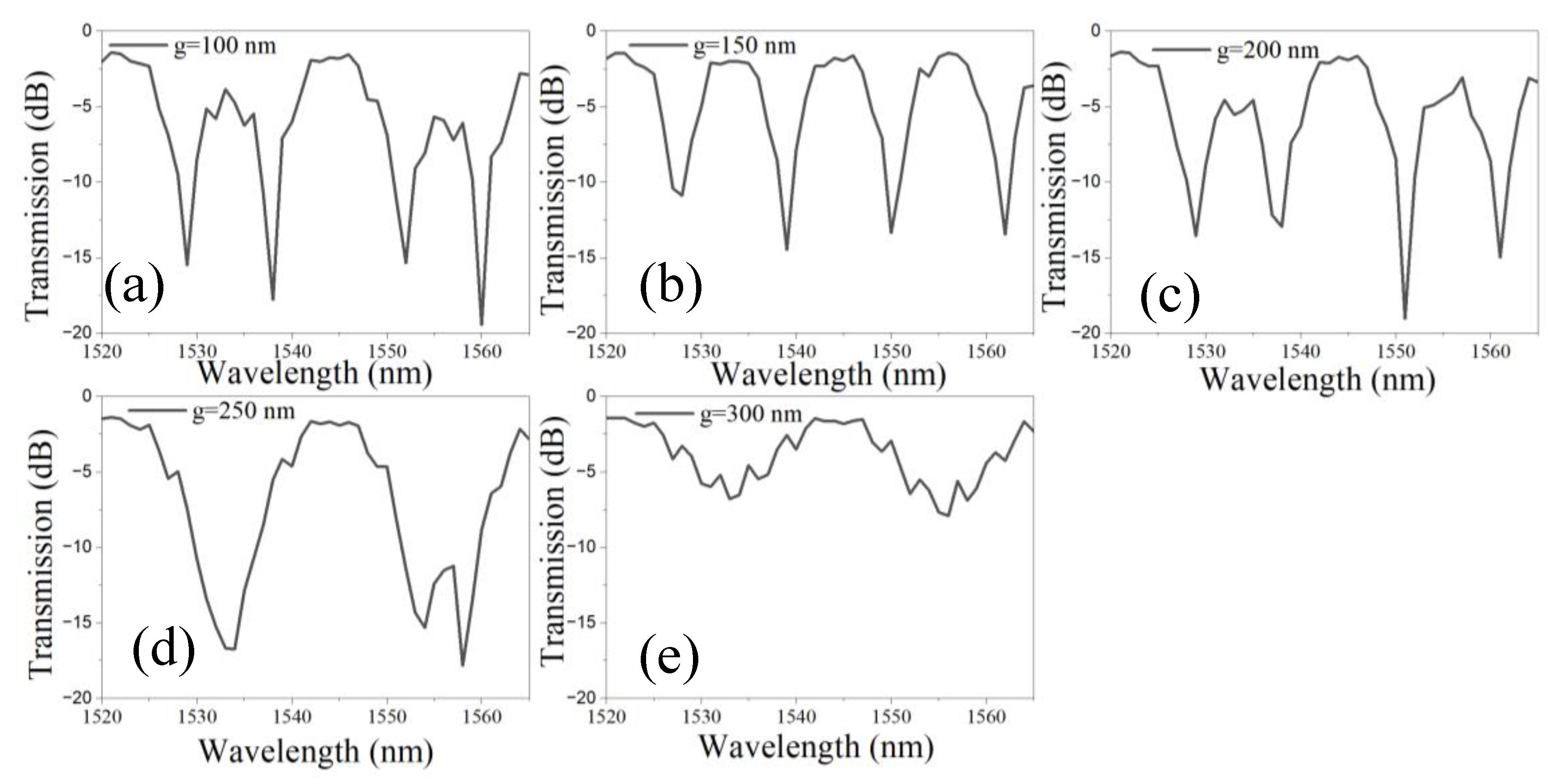
Figure 3.
Transmission spectrum of a-LT-MZI structure for varying Lsens, (a) 10 µm, (b) 20 µm, (c) 30 µm, (d) 40 µm. The remaining geometric parameters are kept constant: R=5 µm, R1=2.5 µm, w=400 nm, LDC=1 µm, g=150 nm, and Lref =19.2 µm.
Figure 3.
Transmission spectrum of a-LT-MZI structure for varying Lsens, (a) 10 µm, (b) 20 µm, (c) 30 µm, (d) 40 µm. The remaining geometric parameters are kept constant: R=5 µm, R1=2.5 µm, w=400 nm, LDC=1 µm, g=150 nm, and Lref =19.2 µm.
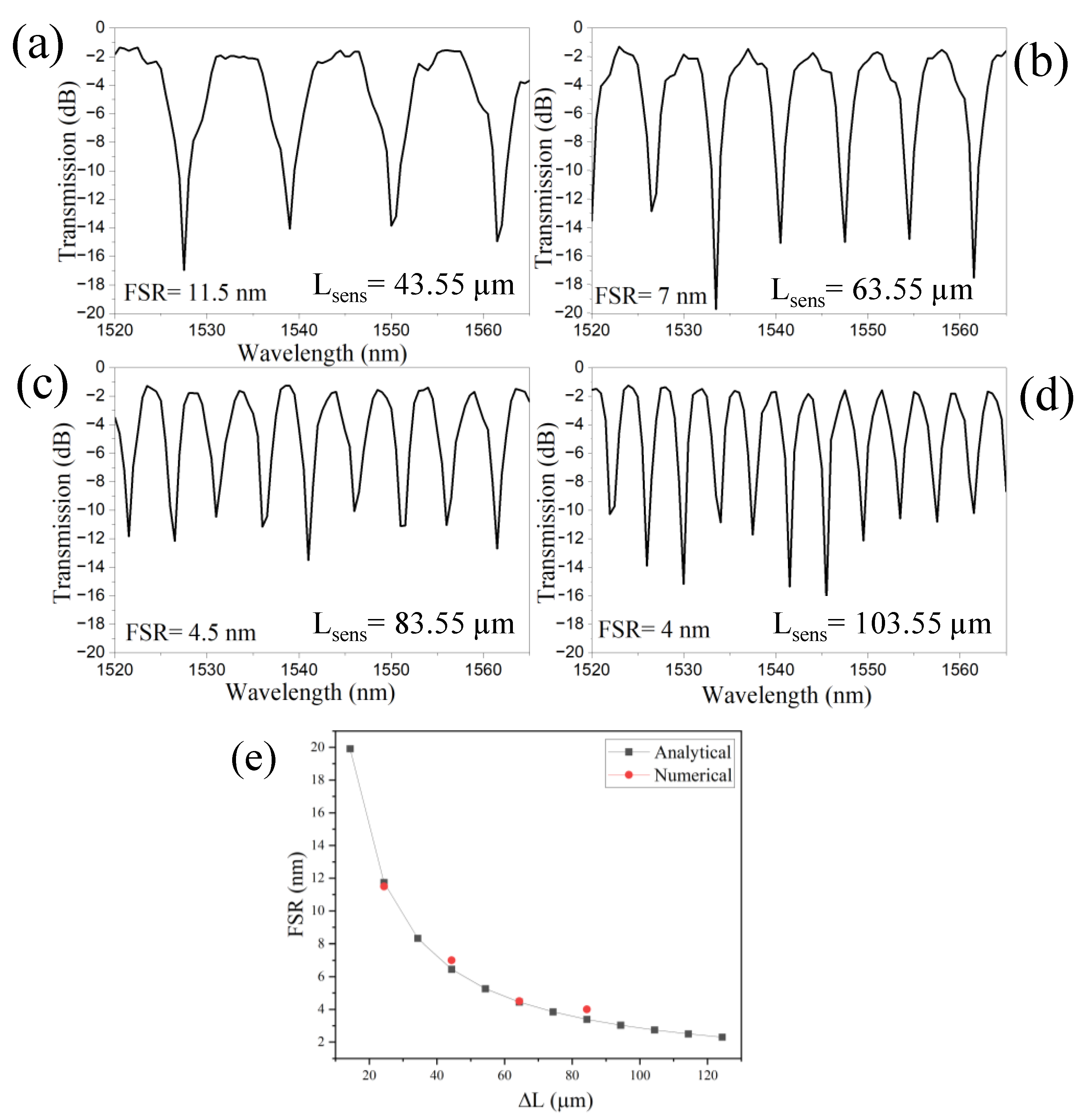
Figure 4.
Transmission spectrum of a-LT-MZI structure for different values of w, (a) 350 nm, (b) 360 nm, (c) 370 nm, (d) 380 nm, (e) 390 nm, (f) 400 nm, (g) 410 nm, (h) 420 nm. The remaining geometric parameters are kept constant: R=5 µm, R1=2.5 µm, g=150 nm, LDC=1 µm, Lsens=43.55 µm, and Lref=19.2 µm.
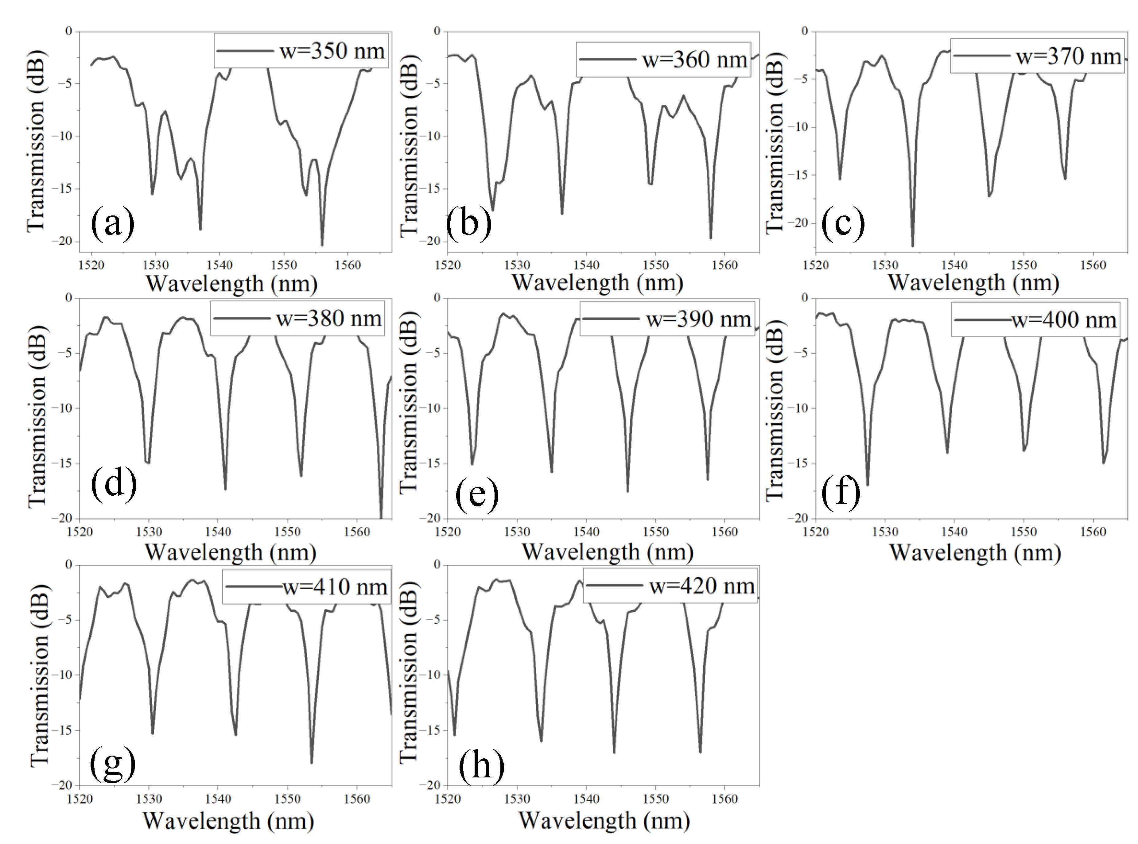
Figure 5.
Normalized H-field distribution in the LT-MZI structure at an operational wavelength of, (a) 1540.5 nm, (b) 1534.5 nm. The geometric parameters of the device are as follows: R=5 µm, R1=2.5 µm, w=400 nm, g=150 nm, LDC=1 µm, Lsens=43.55 µm, and Lref=19.2 µm.
Figure 5.
Normalized H-field distribution in the LT-MZI structure at an operational wavelength of, (a) 1540.5 nm, (b) 1534.5 nm. The geometric parameters of the device are as follows: R=5 µm, R1=2.5 µm, w=400 nm, g=150 nm, LDC=1 µm, Lsens=43.55 µm, and Lref=19.2 µm.
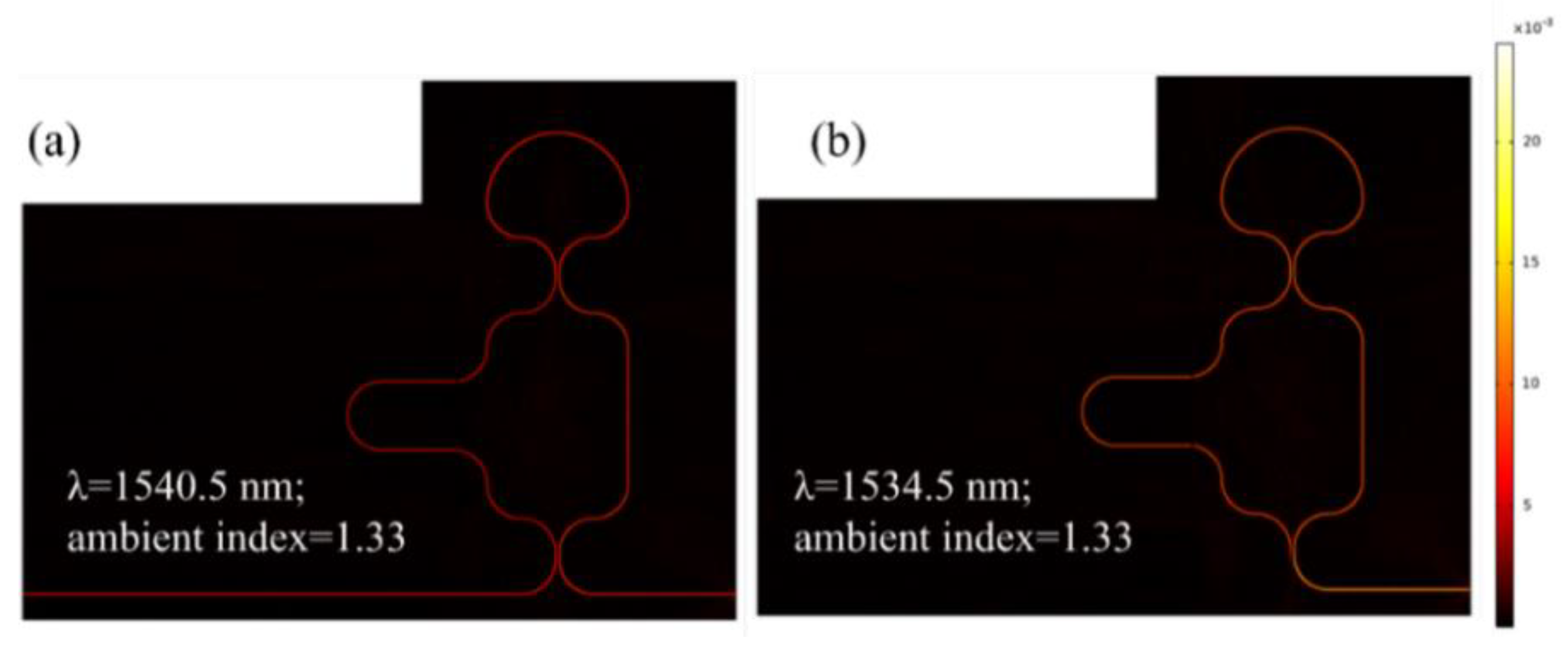
Figure 6.
(a) Transmission spectrum of SWG WG versus wavelength spectrum in the range of 1520 nm and 1565 nm, (b) Norm. H-field distribution in the SWG WG, (I) for D=0.78 and, (II) D =0.71 at an operational wavelength of 1525 nm and 1550 nm, respectively. Transmission spectrum as a function of the ambient RI for (c) a SWG WG with D=0.71 and (d) a standard ridge WG.
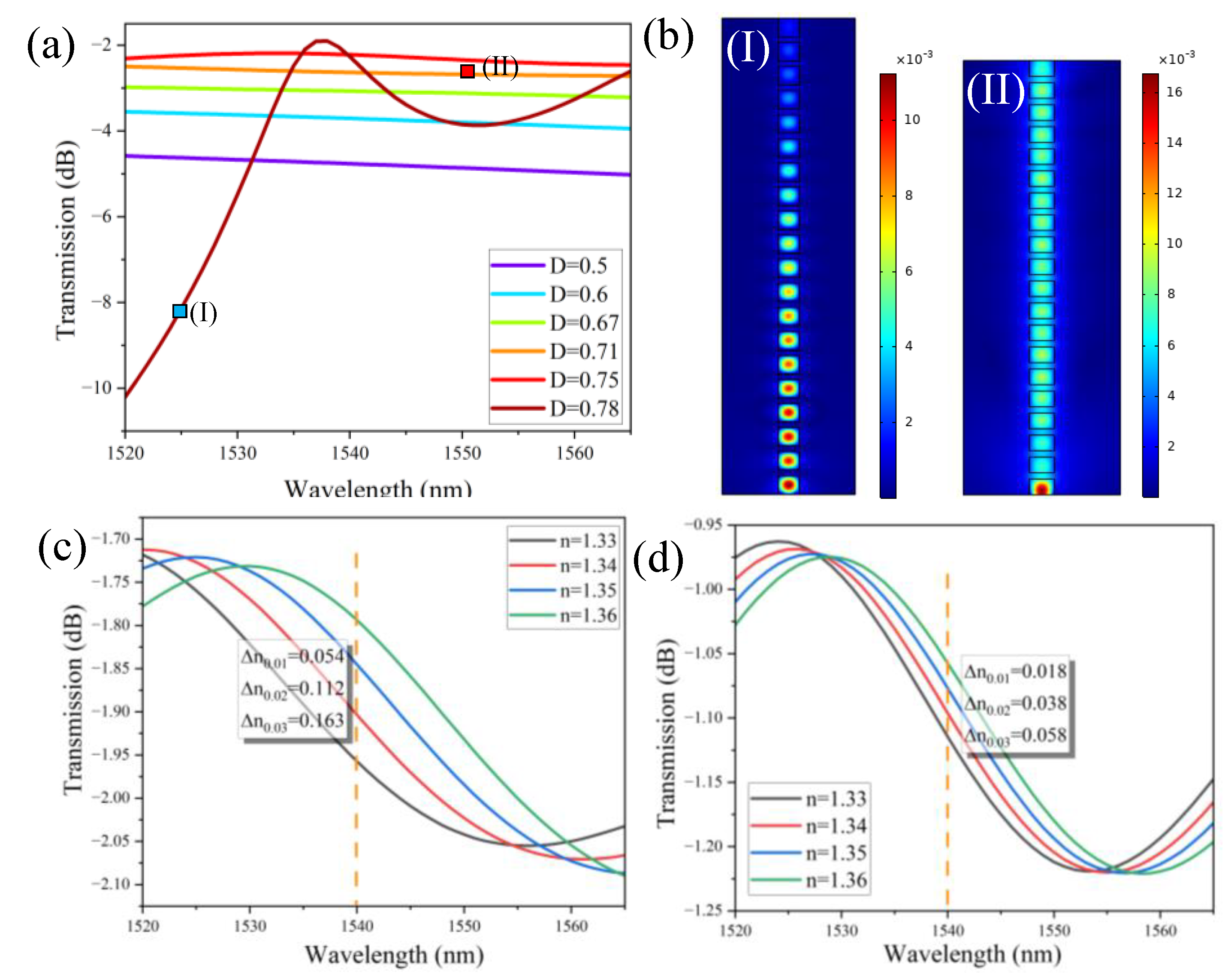
Figure 7.
2D scheme of a-SWG-LT-MZI structure. The straight segment of the sensing arm is replaced with SWG WG for better field overlap with the ambient medium.
Figure 7.
2D scheme of a-SWG-LT-MZI structure. The straight segment of the sensing arm is replaced with SWG WG for better field overlap with the ambient medium.
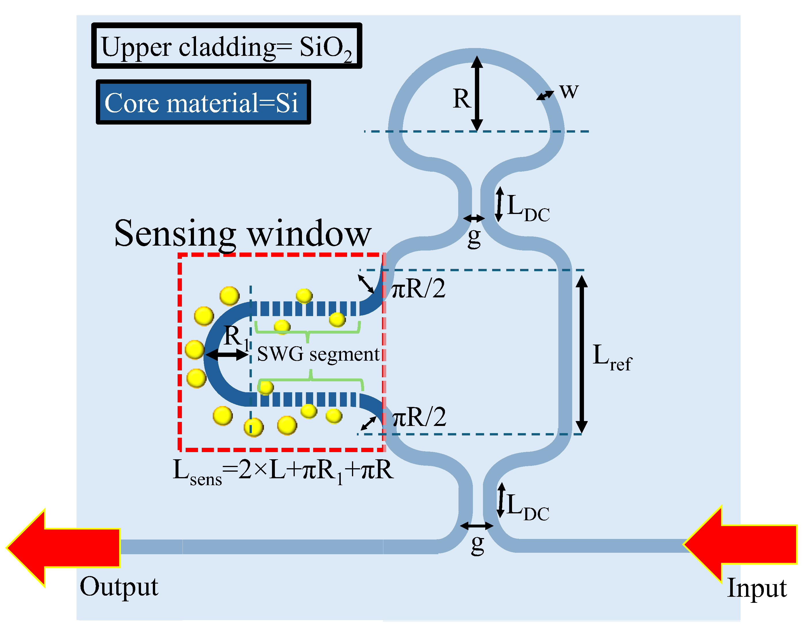
Figure 8.
Normalized H-field distribution in the a-SWG-LT-MZI structure with ΔL=24.35 µm at an operational wavelength of 1535.5 nm, with an ambient RI of 1.33 applied to the sensing arm. Inset the field distribution at different segments of the device.
Figure 8.
Normalized H-field distribution in the a-SWG-LT-MZI structure with ΔL=24.35 µm at an operational wavelength of 1535.5 nm, with an ambient RI of 1.33 applied to the sensing arm. Inset the field distribution at different segments of the device.
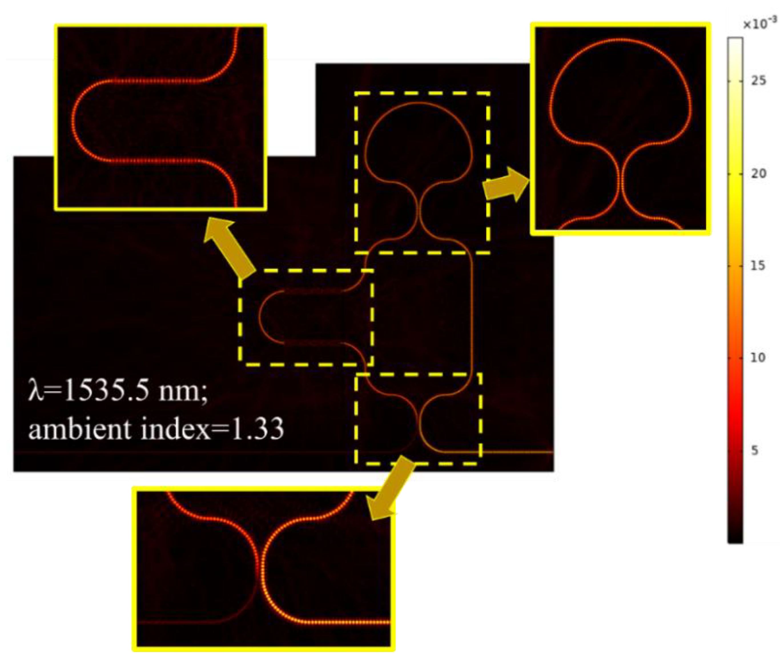
Figure 9.
(a) Transmission spectra for the a-LT-MZI with ΔL=24.35 µm under varying ambient refractive indices. (b) Transmission spectra for the SWG-a-LT-MZI with ΔL=24.35 µm under the same conditions. (c) Comparison of the relationship between the resonance wavelength and the ambient RI for both configurations.
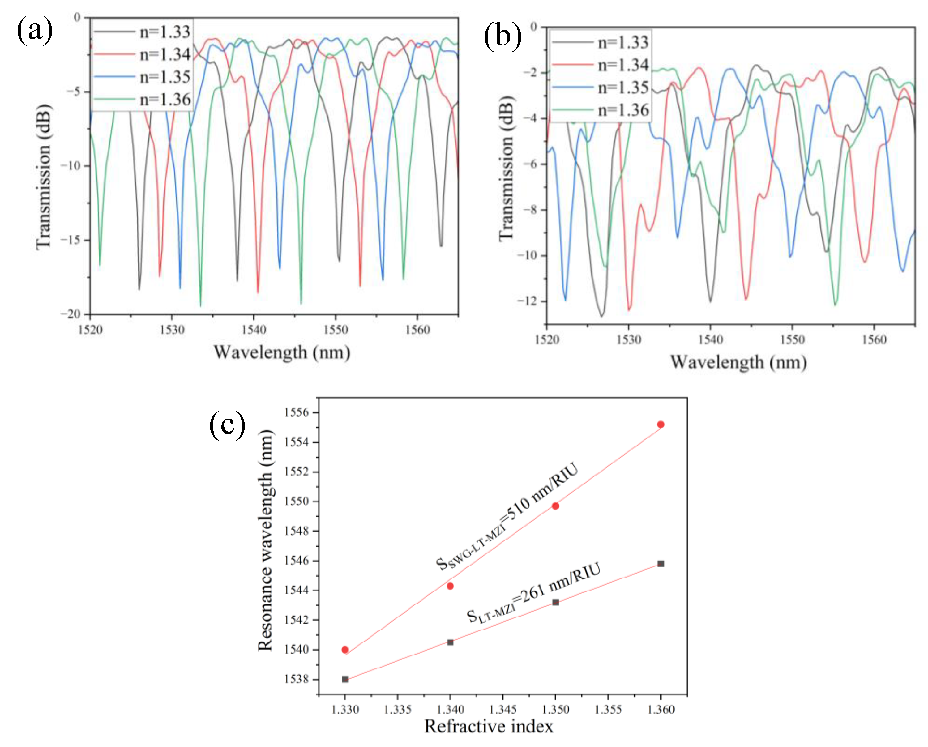

Table 1.
Geometric parameters of the device used in this study.
| Parameters | Description | Values |
| R | The radius of the reflector | 5 µm (fixed value) |
| R1 | The radius of the loop of the sensing arm | 2.5 µm (Fixed) |
| w | Width of WG | 350 nm to 420 nm |
| g | The gap between the WGs | 100 nm to 300 nm |
| LDC | Length of directional coupler | 1 µm |
| Lsens | Length of sensing arm | 2×L+πR1+ πR. Where L=10, 20, 30, 40 µm |
| Lsens | Length of sensing arm for L=10, 20, 30, 40 µm | 43.55, 63.55, 83.55, 103.55 µm |
| Lref | Length of reference arm | 19.2 µm |
| ∆L | Differences in sensing arm and reference arm | 24.35, 44.35, 64.35, 84.35 µm |
| λ | Operational wavelength region | 1520 nm to 1565 nm |
Disclaimer/Publisher’s Note: The statements, opinions and data contained in all publications are solely those of the individual author(s) and contributor(s) and not of MDPI and/or the editor(s). MDPI and/or the editor(s) disclaim responsibility for any injury to people or property resulting from any ideas, methods, instructions or products referred to in the content. |
© 2025 by the authors. Licensee MDPI, Basel, Switzerland. This article is an open access article distributed under the terms and conditions of the Creative Commons Attribution (CC BY) license (http://creativecommons.org/licenses/by/4.0/).
Copyright: This open access article is published under a Creative Commons CC BY 4.0 license, which permit the free download, distribution, and reuse, provided that the author and preprint are cited in any reuse.


