Preprint
Article

This version is not peer-reviewed.

Intelligent Energy Optimization of Parallel Hybrid Vehicles: Control and Monitoring Approach for Regenerative Braking Systems and Solar Panels.

Submitted:

15 January 2025

Posted:

16 January 2025

You are already at the latest version

Abstract

This paper explores an innovative approach to optimize the energy management of hybrid vehicles by integrating regenerative braking and solar panels. Regenerative braking recovers kinetic energy during braking, reducing the dependence on mechanical energy sources, while solar panels convert solar energy to power the electric propulsion system. The study uses computer models and simulations to look at an advanced hybrid system. It focuses on the hybrid inverter and optimization algorithms, like the maximum power tracking (MPPT) algorithm to get the most power from the sun and genetic algorithms to make the best use of energy. Controls like pulse width modulation (PWM) and proportional integral (PI) are used to improve system performance. The vehicle performance is evaluated under various driving conditions, considering variables such as speed, battery charge, current, voltage, acceleration, and flux. Results show that the integration of these technologies reduces fuel consumption and greenhouse gas emissions, contributing to sustainable mobility. This work provides practical recommendations for the automotive industry to promote hybrid vehicles with advanced energy solutions.

Keywords: 
;  ;  ;  ;  

1. Introduction

In a context where environmental issues related to transport occupy a central place, the optimisation of parallel hybrid vehicles is a crucial necessity [1] to reduce greenhouse gas emissions and limit fuel consumption. These vehicles, which combine an internal combustion engine and an electric motor [2], embody a transition towards more sustainable mobility by combining energy efficiency and carbon footprint reduction [3]. However, the quest for a balance between performance, profitability and autonomy remains a major challenge. This research proposes an integrated approach that combines regenerative braking and the use of solar panels, two complementary technologies with promising prospects. Regenerative braking, by recovering the kinetic energy dissipated during braking, offers an opportunity to extend the autonomy of vehicles while reducing their energy consumption [4,5,6,7]. The integration of solar panels on the body or roof of vehicles, on the other hand, allows exploiting a renewable energy source to power the electrical systems and complement the hybrid powertrain [8,9,10]. These solutions, although innovative, raise challenges in terms of design, efficiency under various climatic conditions, and technological integration.
Many studies have been conducted in the field of hybrid and solar vehicles. For example, in [11], the paper explores the fundamental reasons for studying and developing hybrid solar vehicles (HSVs). It focuses on the hybridization of solar energy and internal combustion engines, thus enabling combined propulsion by electric motors and traditional combustion engines. In [12], the authors focus on the hybridization of solar vehicles with internal combustion engines. Their work demonstrates the possibility of driving these vehicles by both solar energy and electric motors while highlighting the associated environmental and energy benefits. In [13], a fuzzy logic-based control strategy is developed for energy management in a parallel hybrid vehicle. This approach allows for efficient energy distribution among the different vehicle components. In [14], the paper introduces digital twin modeling for solar vehicles. It proposes a hybrid modeling method, combining mechanistic and artificial intelligence-based data. The cloud platform and TCP protocol used enable efficient interaction between physical and digital entities. In [15], the authors present a prototype of a solar hybrid vehicle converted from a conventional car. Innovations include the integration of motors in the rear wheels, the addition of flexible photovoltaic panels, and a vehicle management unit, all tested in road trials. In [16], the paper proposes advanced concepts for solar hybrid vehicles, combining internally ignited engines with solar-powered batteries. The use of lightweight materials such as carbon fiber is also highlighted to reduce the overall weight of the vehicles and optimize their energy efficiency. In [17], a method to convert conventional vehicles into solar hybrid vehicles is presented. Using the GREET tool, a life cycle analysis demonstrates the energy and environmental benefits of this approach in the short and medium term. In [18], the paper deals with the simulation and implementation of a solar-powered electric vehicle. The authors focus on the different components, including solar panels, power converters, and BLDC motors, in order to maximize the energy performance. The work presented in [13,19], and [20] analyzes the optimization of parallel hybrid vehicle components, with a particular interest in regenerative braking and fuel consumption reduction. However, these studies do not consider the joint integration of solar panels. The study [21] highlights the use of genetic algorithms to develop advanced energy management strategies adapted to hybrid electric vehicles. In [22], a detailed review of energy storage technologies is provided, highlighting the advantages of lithium-ion batteries and ultracapacitors for electric vehicles, as well as an in-depth comparison of their performance. The study [23] proposes a control strategy based on the FQL algorithm to optimize regenerative braking. Furthermore, [19] develops a multi-objective genetic algorithm (MOGA) to optimize the dimensions of powertrain components and reduce emissions. Unlike these works, our method also integrates the management of solar panels into the overall optimization.
Despite these significant contributions, there is a lack of integrated approaches that simultaneously exploit the potential of regenerative braking and solar panels in parallel hybrid vehicles. This work stands out by filling this gap with a holistic methodology aimed at:
1. Maximizing energy recovery during regenerative braking through optimized management and storage systems.
2. Evaluating the impact of solar panels on autonomy and energy efficiency under different usage and climatic conditions.
3. Designing aesthetic and efficient solutions to integrate solar panels while ensuring safety.
4. Analyzing the economic viability of this approach by comparing the costs of the technologies with the savings achieved in the long term.
5. Identifying the barriers and levers of adoption to propose effective awareness-raising strategies.
Building on these objectives, this research aims to contribute to the design of more efficient and environmentally friendly parallel hybrid vehicles. It directly addresses sustainability issues and offers an innovative response to mobility challenges, paving the way for a simultaneous reduction in carbon emissions and dependence on fossil fuels.

2. Materials and Methods

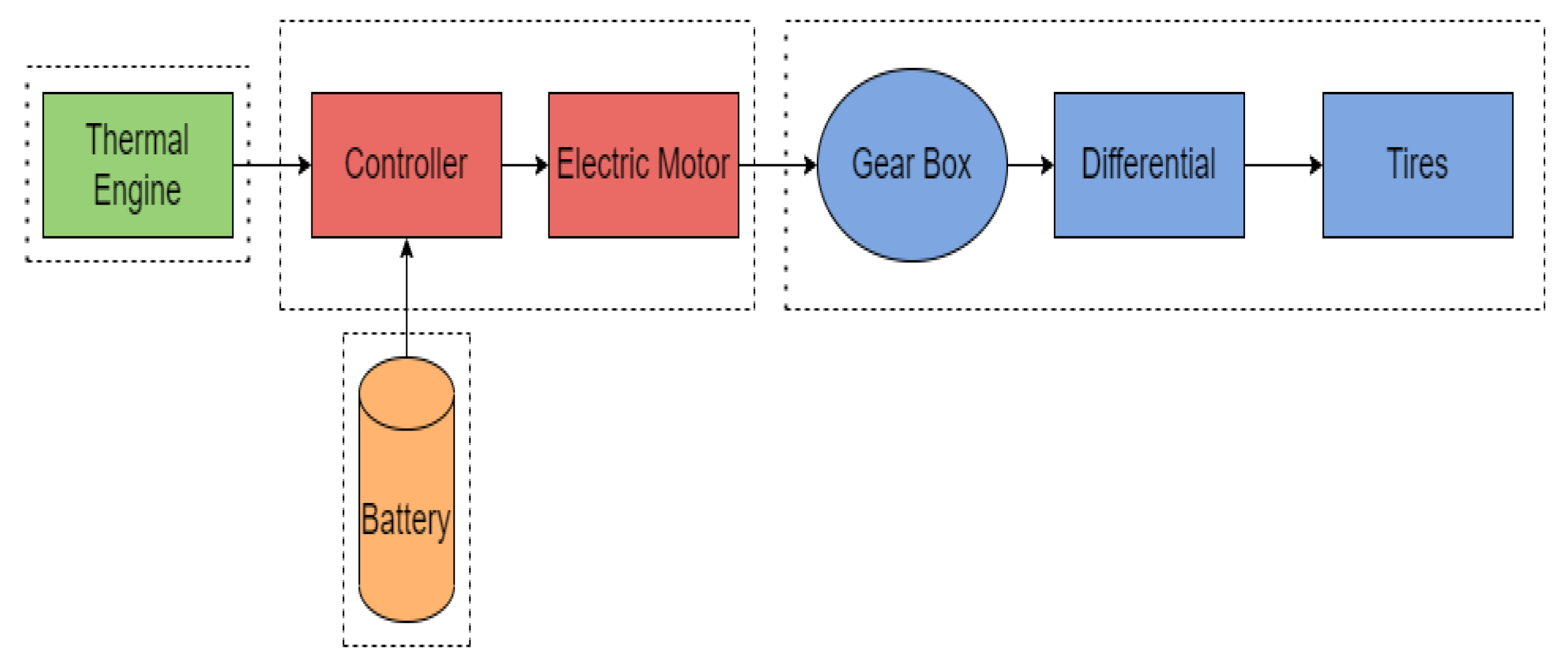
2.1. Hybrid System Description

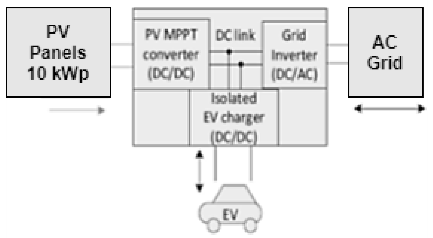
2.1.1. Block Diagram

In a parallel hybrid electric system, a heat engine and an electric motor work in parallel to provide power to the vehicle wheels [20]. This type of system combines the energy of the two motors, allowing optimizing fuel consumption and reducing emissions. In the diagram, the two motors can operate independently or in combination. The system alternates between several operating modes (electric, pure, heat, hybrid) depending on the power demand and the battery charge level. The heat engine, the electric motor, the battery, the supercapacitor or generator, and the power management system that interact to propel the vehicle are illustrated in Figure 1.
The main components and their role in the block diagram are presented as follows.
The heat engine generates mechanical energy that is sent to the controller to be used as needed. The controller manages the energy sent to the electric motor, either in hybrid mode or in all-electric mode, depending on the energy management strategy. The energy from the electric motor is sent to the gearbox, which distributes this energy to the wheels for propulsion. The heat engine can also send energy to the gearbox for propulsion or to charge the battery in hybrid mode. The gearbox manages the power coming from the motors and transmits this power to the wheels. In a hybrid vehicle, the gearbox can have fixed or variable ratios. After the gearbox, the differential is placed to distribute the power to the wheels while allowing them to rotate at different speeds. The drive wheels receive mechanical or electrical power and are driven by the gearbox and the differential.

2.2. Different Categories of Vehicle Hybridization

We are now interested in hybrid vehicles, and we classify vehicles by hybridization range, then according to the architecture of the vehicles.

2.2.1. Electric Hybridization Range

Depending on the degree of hybridization, several ranges of hybrid vehicles exist:
• Micro hybrid: the electric machine will be low power compared to the total traction power. It will function, for example, as an alternator-starter. An interesting application is the star/stop, which allows the combustion engine to be stopped during a traffic jam or in front of traffic lights in order to save fuel. This solution is marketed, for example, on the Citroën C2 and C3 models and is in the process of being generalized on European passenger vehicles. The electric power is in this case less than 10% of the total power.
• Mild hybrid or semi-hybrid: the level of hybridization is slightly higher than the micro hybrid. The Start/Stop application is also possible, but the electric machine is then able to operate as a generator during braking, which allows the kinetic energy to be recovered and stored in electrical form in the batteries/supercapacitors. However, when the vehicle is operating at low speed, the electric machine cannot drive the vehicle on its own. This solution is used, for example, by BMW, Honda (Honda Insight), Mazda, Demio, and Ford and is called Urban Hybrid by PSA (concept car C5-airscape). The electric power in this case is between 10 and 30% of the total power.
• Full hybrid: Compared to mild hybrids, in this range of hybrids, the electric machine is able to drive the vehicle on its own. This solution is used by the Toyota Prius II, as well as the Lexus RX 400H and GS 450 H. The electric power in this case is greater than 30% of the total power.
• Plug-in hybrid: This is a full hybrid with a larger battery capacity that can be charged via a conventional 110 V or 220 V electrical outlet. Therefore, this solution provides greater autonomy in all-electric mode. The first prototype of a plug-in hybrid was designed in 2004 by the non-profit organization The California Cars Initiative, created in 2002.
Our vehicle’s study, which combines regenerative braking with solar panels to recharge its battery, falls into the categories of full hybrid. The vehicle uses the energy recovered by regenerative braking to recharge its battery, but it does not recharge from an external source. This vehicle is equipped with solar panels to supplement the charging, although this remains rare and limited to a small amount of energy due to the available surface area.

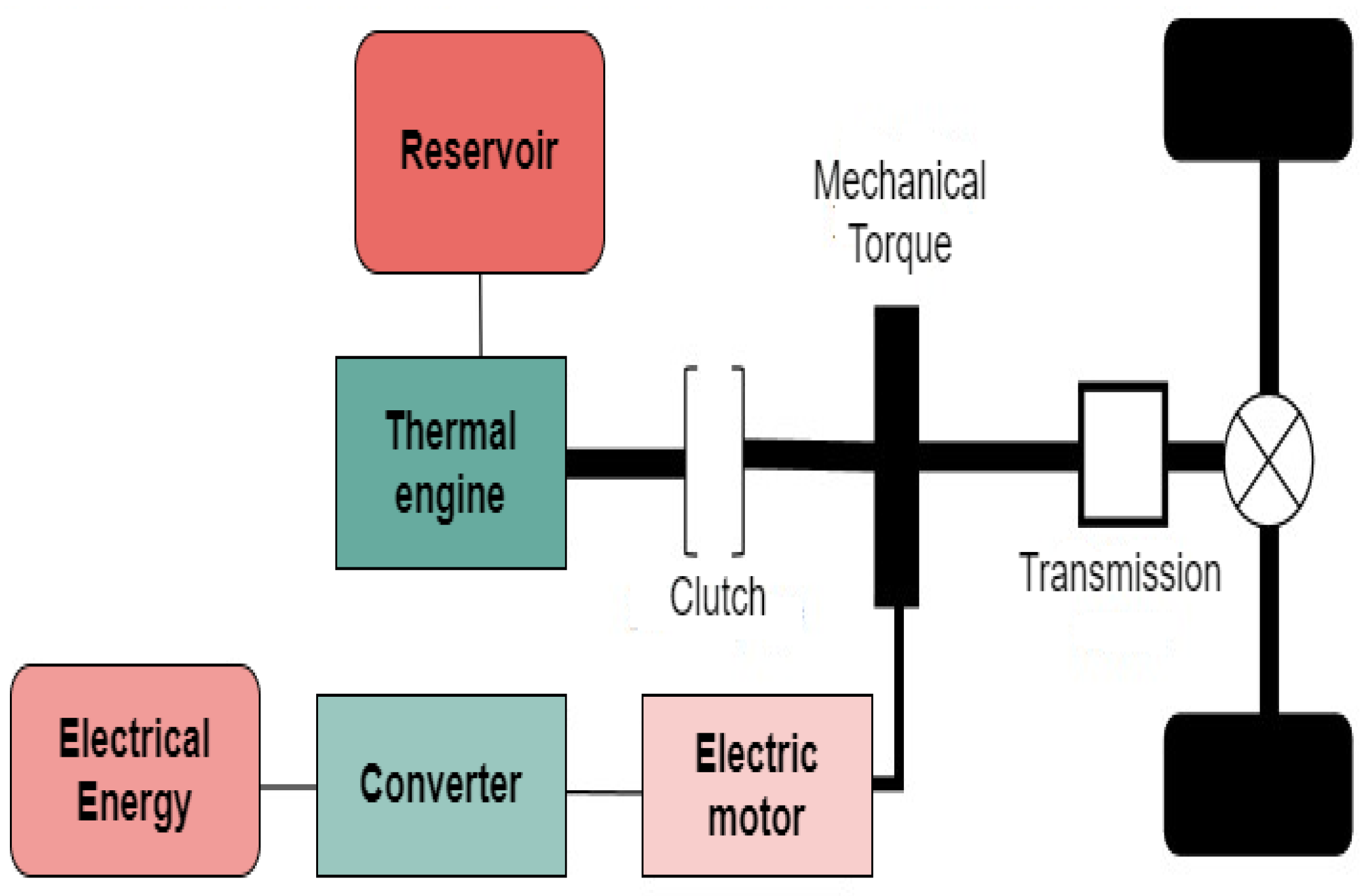
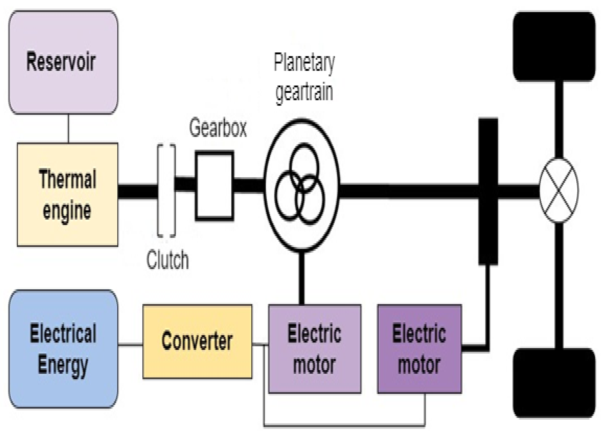
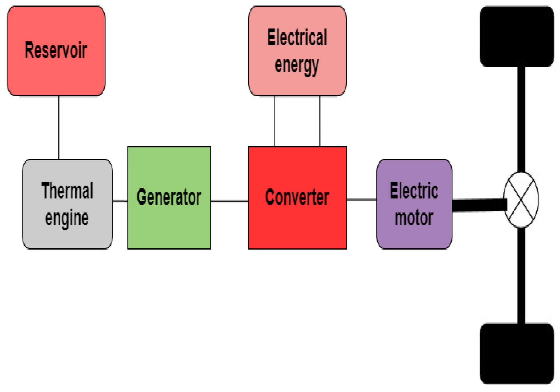
2.1.2. Hybrid Electric Architecture

The first hybrid thermal-electric vehicle was produced in 1898. It was the Lohner-Porsche known as “the chair,” equipped with a combustion engine and electric motors located in the hubs of the front wheels. This series hybrid vehicle was initially an electric vehicle presented at the Paris World’s Fair, to which F. Porsche added a thermal engine and a dynamo. To return to our time, we analyze below the three major hybrid electric structures currently encountered [24].
1). Serie hybrid architecture
In this architecture, the thermal engine provides the energy to power the electric generator, this electrical energy being used to drive the electric motor, which provides mechanical power to the vehicle’s wheels. The advantage is possibly the recovery of energy in the batteries/supercapacitors during braking operation. This architecture is equivalent to the all-electric architecture by adding a generator. In this case, the thermal engine does not directly drive the wheels. The energy conversion flow is thermal, mechanical, and electrical. These multiple energy conversions limit the maximum efficiency of this drive chain. Regarding the regenerative braking function of the full hybrid vehicle, since the battery capacity is low, the energy that can be recovered is limited. As an advantage of the architecture, less relative pollution and ease of control, and as a disadvantage, low overall efficiency and a large electric motor, high cost (three maximum power machines). The block diagram of the series hybrid architecture is given in Figure 2.
2). Parallel hybrid architecture
In this configuration, the heat engine and the electric motor can each transmit their power to the wheels without directly depending on each other, thanks to mechanical transmissions. This system has several advantages, including increased efficiency in all-electric mode, energy recovery during braking, and automatic shutdown of the thermal engine when not required [21]. On the other hand, a weak point lies in the interruption of torque observed during gear changes. Figure 2 illustrates the general principle of the parallel hybrid architecture.
Figure 3. Parallel hybrid architecture.
Preprints 146296 g003
3). Series/parallel hybrid architecture
We can also call this architecture Split, ’power derivation,’ or mixed.
• The series/parallel hybrid architecture solution allows the coupling of thermal and electric engines thanks to a dedicated transmission using clutches. This is the type of transmission used for the Nissan Tino hybrid vehicle.
• The series/parallel hybrid or power derivation architecture has also been implemented on the Toyota Prius vehicle. The coupling of the engines is provided here by an epicyclical gear train, which is a mechanical device allowing the distribution of mechanical powers according to the operation. It is then theoretically possible for the thermal engine to operate almost continuously at its best operating point (in terms of efficiency). As an advantage, it combines the advantages of the series hybrid and the parallel hybrid, and as a disadvantage, it has control complexity and high cost. Figure 3 below is a representation of the series/parallel architecture.
Figure 4. Serie-parallel hybrid architecture.
Preprints 146296 g004
We have chosen the parallel hybrid architecture for this article just because, out of the two other architectures, series and series/parallel, the parallel hybrid structure is characterized by the following points:
– The parallel configuration allows the thermal engine and the electric motor to be used independently or simultaneously, thus offering more flexibility to optimize energy consumption according to driving conditions.
– As the electric motor is directly connected to the wheels, it allows for efficiently recovering energy during braking, thus maximizing overall efficiency.
– Compared to a series-parallel architecture, the parallel architecture is simpler to design and manage while offering excellent energy optimization.
– This configuration offers a good compromise between performance, complexity, and cost, especially when trying to integrate technologies such as regenerative braking and the use of solar panels.

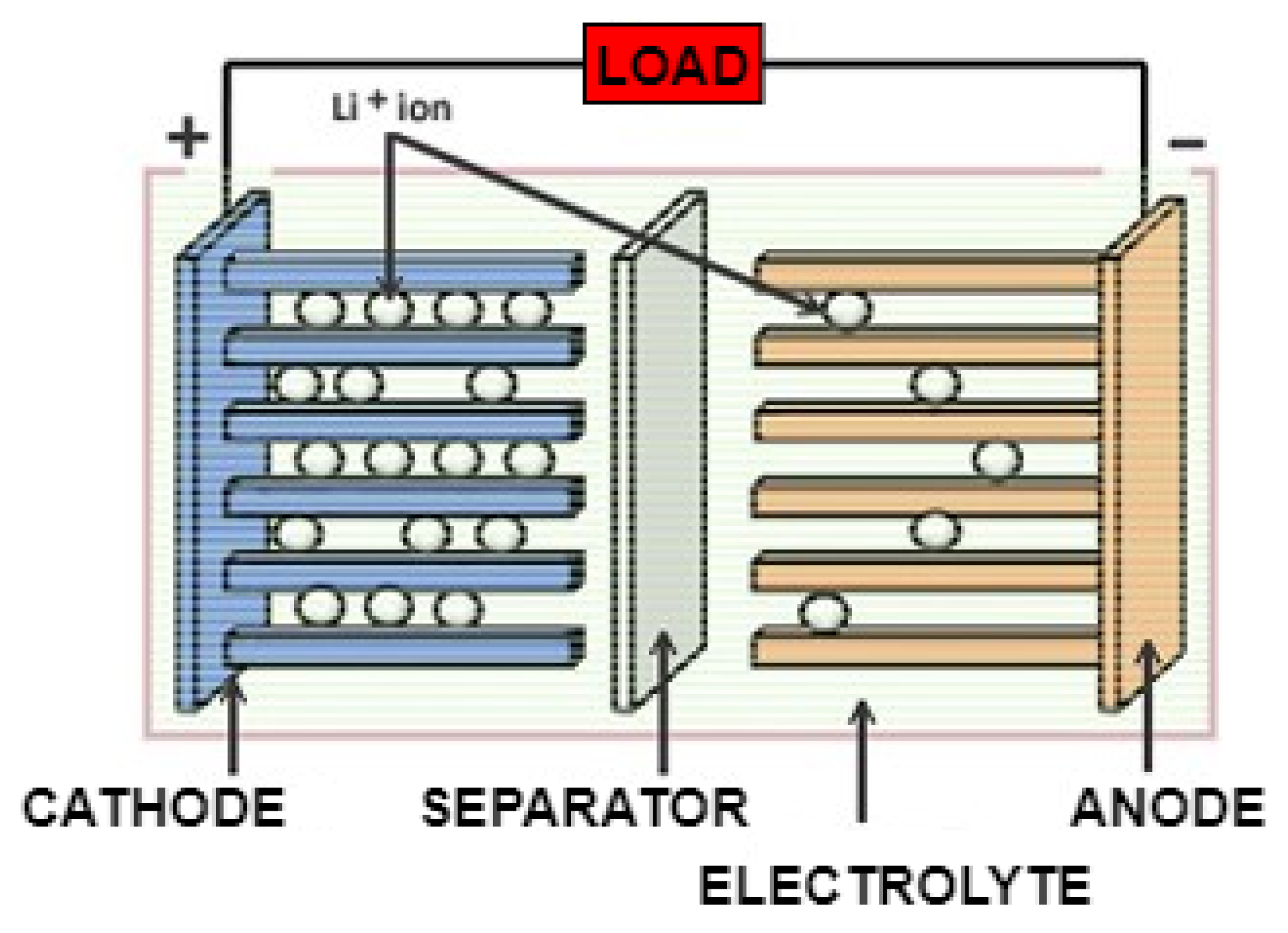
2.1.3. Components of Hybrid Vehicles

1) Heat engine
The internal combustion engine works by burning a mixture of fuel and air, creating pressure that moves a piston to generate mechanical energy. It is composed of several key elements, such as the cylinder, the piston, and the crankshaft, and it also follows a four-stroke cycle. There are gasoline engines and diesel engines, each with its own characteristics. Despite its efficiency and wide use in vehicles, this type of engine is criticized for its polluting emissions, which encourages the development of greener alternatives such as the electric motor.
2) Electric motor
The electric motor converts mechanical energy via magnetic fields that turn a rotor. There are two main types: direct current (DC) and alternating current (AC), used in applications such as electric vehicles and industrial devices. Among them, the permanent magnet motor is particularly efficient, as it uses magnets to generate the magnetic field without an additional power supply, increasing efficiency by often reaching 90-95% in the best conditions and reducing energy losses. This type of motor is silent, without direct emissions of pollutants, and is preferred for its durability and ecological efficiency.
3) Battery
Lithium-ion (Li-ion) batteries are among the rechargeable batteries that stand out for their large energy capacity and high power [25]. This advanced technology is based on the central role of lithium ions in electrochemical functioning. Li-ion battery cathodes are made from intercalated lithium compounds, such as cobalt-lithium oxide (LiCoO2), manganese-lithium oxide (LiMn2O4), or nickel-lithium oxide (LiNiO2) [26]. As for the anode, it is generally made of graphite, used as an intercalation material. These two electrodes are separated by an electrical insulator called a separator and immersed in an electrolyte made up of organic solvents containing a lithium salt. Thanks to their flexible structure and efficient chemistry, lithium-ion batteries are suitable for many applications, ranging from common electronic devices to systems requiring high power, such as hybrid vehicles.
Figure 5. Lithium-Ion Battery.
Preprints 146296 g005
4). Converter
In electric vehicles, the converter adapts the voltage between the battery and the motor to optimize performance. It converts the direct current (DC) of the battery into alternating current (AC) for the motor and enables regenerative braking [27,28,29,30]. Modern converters use components like Metal-Oxide-Semiconductor Field-Effect Transistor (MOSFET) and Insulated Gate Bipolar Transistor (IGBT), due to their efficiency and ability to handle power requirements. MOSFETs [22,23] are suitable for low- to medium-power with fast switching requirements, while IGBTs are preferred for high-power and high-voltage applications.
5). Hybrid inverter
For a hybrid electric vehicle combining regenerative braking and a solar panel, the properties of the hybrid inverter include the ability to convert solar energy and energy generated by regenerative braking into usable current to power the vehicle’s electrical systems. The hybrid inverter is also capable of storing excess energy in the battery for later use, and it allows switching between energy sources seamlessly to maximize the vehicle’s efficiency and range. The type of current in the hybrid inverter mainly depends on the specific application and system components [31,32]. In the case of hybrid electric vehicles, the current is direct current (DC) at the inverter input and then converted to alternating current (AC) to power the vehicle’s electrical systems. The level of the inverter used for the hybrid electric vehicle’s traction depends on various factors such as the required power, desired efficiency, and system complexity. For vehicle traction applications, high-power and high-efficiency inverters have been used to ensure optimum performance and long battery life. A medium- to high-voltage inverter could be used to handle the high power requirements of vehicle traction.
6). Supercapacitors
Due to their high capacity, instantaneous power, and durability, they play a key role in hybrid vehicles as a complement to batteries. They are particularly effective for kinetic energy recovery during braking, assisting starting and acceleration, and supporting auxiliary systems. Although they have a lower energy density than batteries, their advantages include extended life and temperature resistance. Supercapacitors complement hybrid vehicle batteries by absorbing power peaks, quickly recovering energy during braking, and reducing battery wear. This extends the life, improves energy efficiency, stabilizes the system, and optimizes performance, even in extreme conditions. Their use reduces maintenance costs, enhances environmental sustainability, and provides an innovative solution for high-performance and reliable vehicles.
7). Solar panel charging
Solar panels on hybrid electric vehicles help recharge the auxiliary battery, which can extend the range by powering the vehicle’s electrical systems. However, their efficiency depends on factors such as the size of the panel, sunlight, and vehicle use [33]. They generally cannot provide enough energy to power the vehicle alone, but they can contribute to reduced fuel consumption and emissions [34]. Since the vehicle has the panel on its roof, it only works whenever the vehicle is at rest. The equation to calculate the maximum power that the solar panel can produce under ideal conditions is:
P = A × G × η
η = P s P i × 100
Where: is the power generated by the solar panel in watts (W), is the surface area of the solar panel exposed to the sun in square meters ( m 2 ), is the average solar irradiance in watts per square meter ( W / m 2 ), which depends on the geographical location and weather conditions, η is the efficiency of the solar panel, expressed as a percentage, is the output power of the panel, the power actually produced by the panel, is the incident power on the panel which is the total amount of solar energy that hits the surface of the panel.
Figure 6. Architecture scheme of PV-grid and EV charging [35].
Preprints 146296 g006
8). Regenerative braking
Regenerative braking makes it possible to recover part of the kinetic energy produced during braking to transform it into electrical energy, used to recharge the battery of a hybrid electric vehicle [36]. When the driver brakes, the electric motors operate as generators, converting kinetic energy into electricity stored in the battery. This mechanism increases the vehicle’s autonomy while improving its energy efficiency.
During braking, the permanent magnet synchronous machine (PMSM) behaves like a generator. Under the effect of braking, the wheels drive the PMSM, which transforms the kinetic energy of rotation into electrical energy. Furthermore, in hybrid vehicles, the thermal engine (ICE) intervenes to recharge the battery when necessary. When the charge level is low, the ICE kicks in to generate electricity, feeding the battery and helping to power the electric propulsion system.
Figure 7. Regenerative Braking.
Preprints 146296 g007

2.3. Integrated Energy Optimization Approach for Parallel Hybrid Vehicles

To model the systems related to energy recovery, battery charge management, and the use of solar panels, the essential equations to describe the dynamics of energy flows in a hybrid vehicle are described as:
The kinetic energy of a vehicle can be recovered during braking. This equation is translated by (3).
E k = 1 2 m v 2
v : Vehicle speed ( m / s ).
Taking into account the losses (efficiency η r ), the recovered energy E r is given by equation (4).
E r = η r . 1 2 m v 2
Battery dynamics can be modeled through energy flows (charge/discharge) and system voltage. This equation is given by (5).
d E b d t = P i n P o u t P l o s s e s
P o u t : Power supplied by the battery to the engine or auxiliary systems;
P l o s s e s : Internal losses of the battery ( P l o s s e s = I 2 . R b ), where I is the current and R b the internal resistance.
The energy produced by the panels depends on the light intensity and their efficiency. The equation for the captured solar power is given by (6).
P s o l a r t = η s . A . I t
A : Panel surface ( m 2 );
I t : Light intensity received ( W / m 2 ).
The dynamics of the overall energy flows is modeled by the equation of the total energy available in the system. This equation is given by (7).
E t o t a l = E b + E m o t o r + E l o s s e s + E a u x
E l o s s e s : Total losses in the system;
E a u x : Energy consumed by auxiliary loads.
These equations allow optimizing the general energy behavior of the hybrid vehicle.
For a good modeling of these equations with the MPPT algorithm and the PI control, we must note that the MPPT algorithm maximizes the power of the solar panels by dynamically regulating their voltage: equation (8) allows understanding the relationship.
P = V . I
By deriving equation (8) with respect to the voltage, we obtain equation (9).
d P d V 0
Relation (9) allows seeing that the solar panel operates at the maximum power point.

2.3.1. Proportional Integral (PI) Controller

The PI controller is integrated into the energy management system to optimize regenerative braking. By dynamically adjusting the braking parameters according to speed variations and driving conditions, it maximizes energy recovery while ensuring a smooth and safe driving experience. It stabilizes the maximum power point by regulating the error between the measured voltage V m e a s u r e d and the set point V M P P T : equations (10) and (11) provide a better understanding of this phenomenon.
e t = V M P P T V m e a s u r e d
u t = K p e t + K i e t d t
e t : Error between the setpoint V M P P T and the actual measurement V m e a s u r e d ;
K p , K i : proportional and integral gains. These two mechanisms work together to maximize and stabilize the captured solar energy.

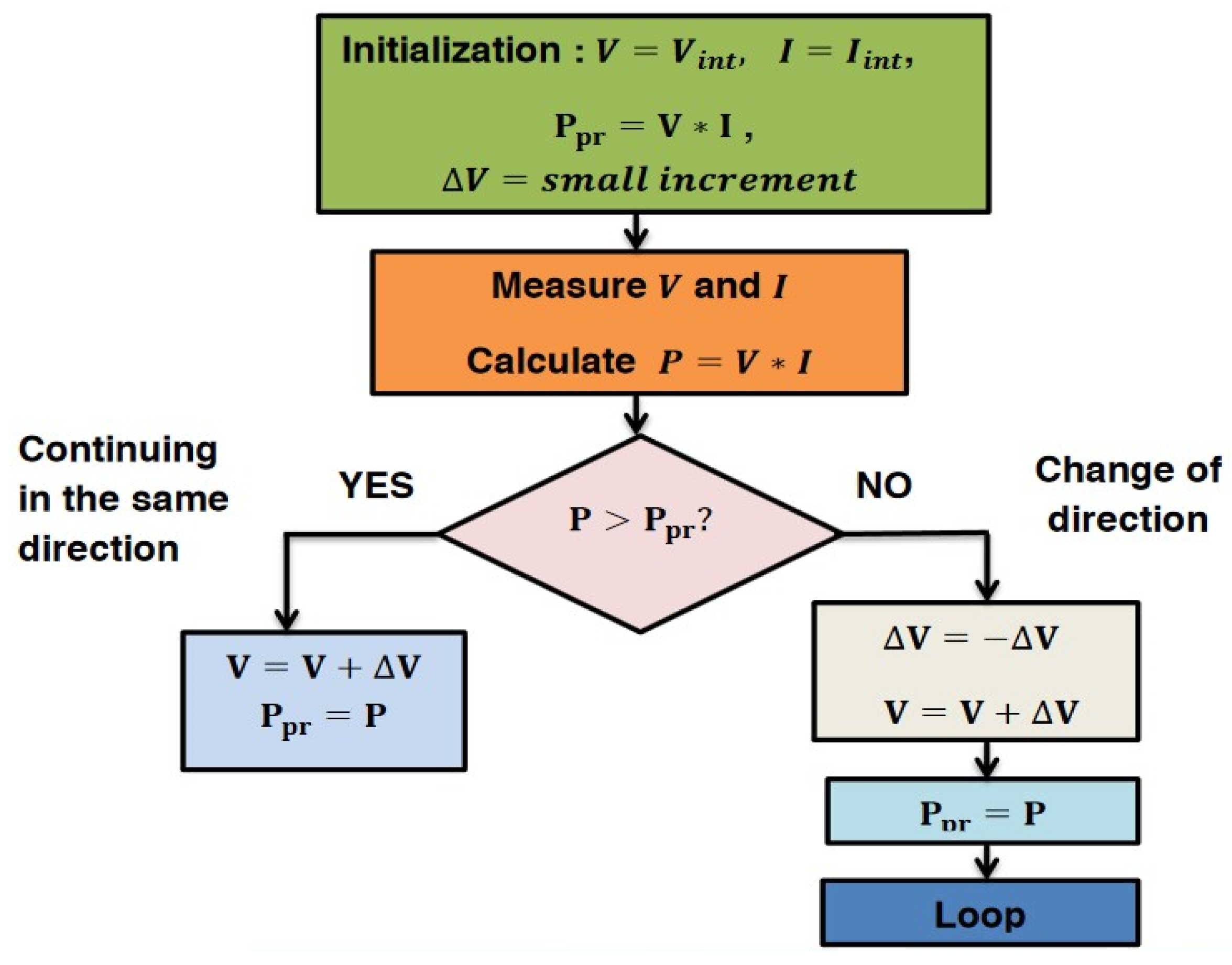
2.3.2. Maximum Power Point Tracking (MPPT) Algorithm

The maximum power point tracking (MPPT) algorithm optimizes solar energy capture by dynamically adjusting the operating point of the panels to maximize power. The PI control stabilizes this point by correcting the deviations between the measured voltage and the optimal one, ensuring a stable and efficient power supply. Their interaction ensures optimal energy management, with a maximum and stable transfer to the batteries or supercapacitors.
The maximum power point of the solar panels, thus optimizing the conversion efficiency of solar energy into electrical energy, ensures that the solar panels always operate at their optimal efficiency value, even in the event of variations in lighting or temperature conditions. Here is an example of a flowchart representing a Perturb and Observe (P&O) MPPT algorithm, which we have adapted to the case of the solar panel system of a hybrid electric vehicle with regenerative braking. With V, I, and P, the current voltage, current, and current power of the solar panel, and respectively the previous power, the initial voltage, and the initial current of the solar panel, ∆V is the small voltage increment. The figure below represents our algorithm.
Figure 8. Flowchart of an MPPT algorithm.
Preprints 146296 g008

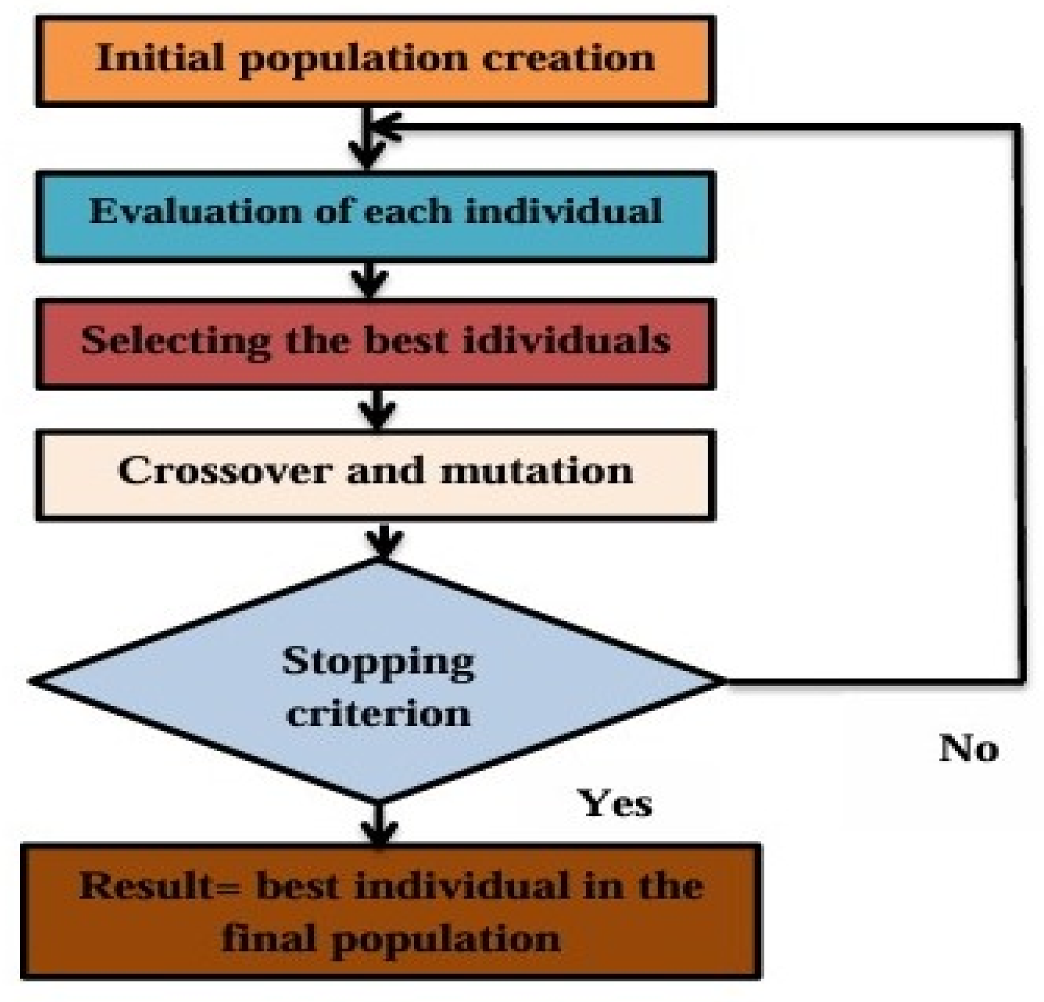
2.3.3. Genetic Algorithms (GA)

Genetic algorithms (GA) optimize energy management by simulating an evolution. The fitness function guides the algorithm to minimize consumption and maximize efficiency. This is justified by equation (12).
f x = w 1 . C f + w 2 . 1 E r e n e w a b l e + w 3 . 1 S O C
E r e n e w a b l e : Energy from solar panels and supercapacitors,
S O C : Battery state of charge,
w 1 , w 2 , w 3 : weighting according to priorities.
This equation evaluates the quality of each candidate solution.
Inspired by the concepts of natural selection and genetics, genetic algorithms (GAs) serve as powerful tools for search and optimization. In our case, evolutionary algorithms (EAs), which encompass GAs, were utilized. They combine genetic algorithms imagined by Holland [37], evolutionary programming introduced by Fogel [38], evolutionary strategies initiated by Rechenberg and Chwefel [39].
The selection, crossover, and mutation steps allow various combinations to be explored in order to converge towards an optimal solution that balances fuel consumption, renewable energy, and battery life. The diagram below illustrates how our algorithm works.
Figure 9. Flowchart of a genetic algorithm.
Preprints 146296 g009

2.3.4. Pulse Width Modulation (PWM)

This is a key technique for controlling inverters in hybrid power management systems, such as those integrating solar panels, supercapacitors, and batteries. It efficiently converts energy between these different sources by modulating voltages and currents to meet the needs of the loads. With PWM, inverters produce high-quality signals with minimized losses, thereby improving overall system efficiency. The technique also optimizes the management of the state of charge (SOC) of batteries and facilitates the integration of supercapacitors to meet rapid variations in energy demand. By reducing thermal and harmonic losses, PWM improves system reliability and efficiency while adapting to fluctuations in renewable sources such as solar panels.

2.3.5. Integration Logic
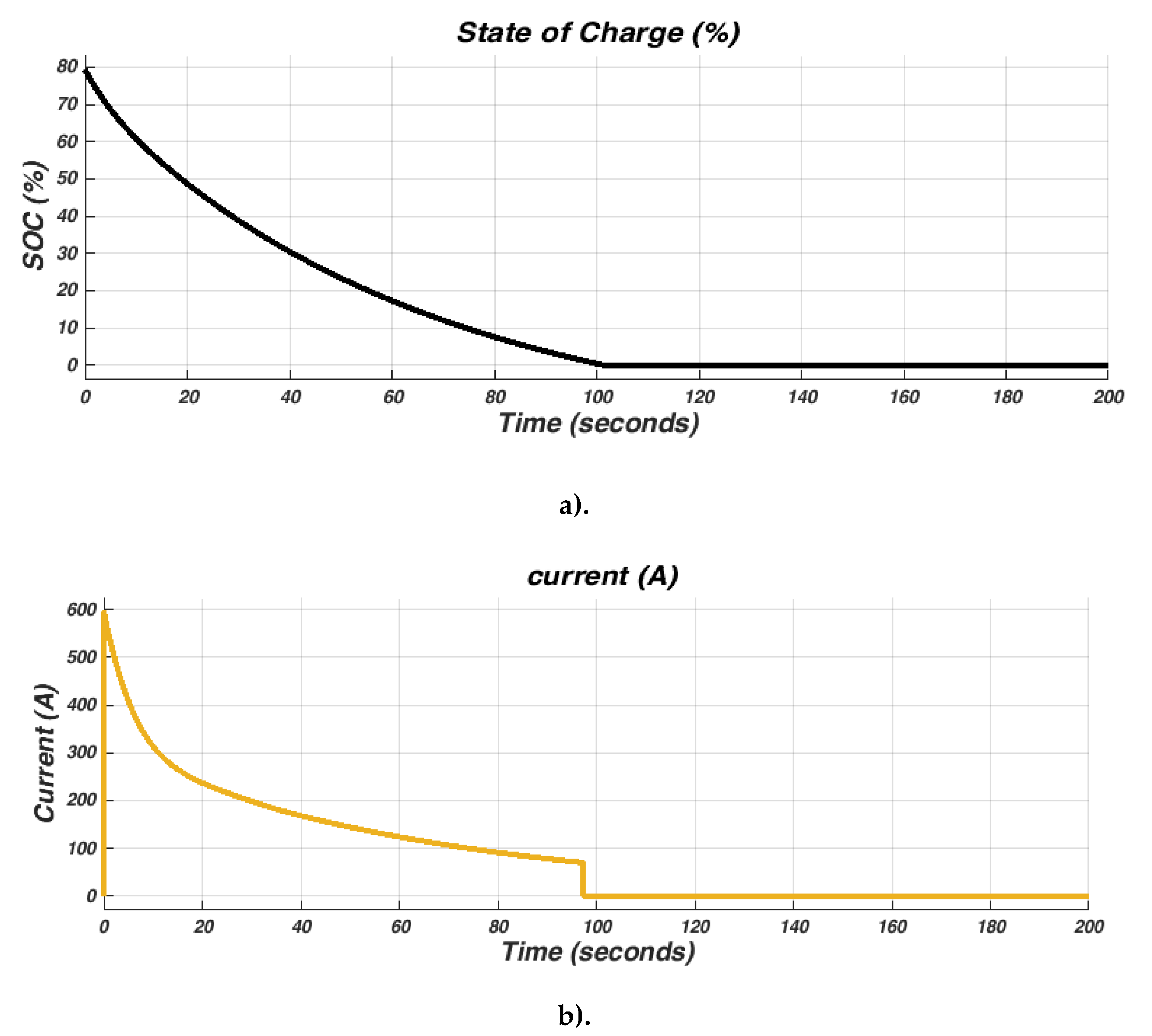
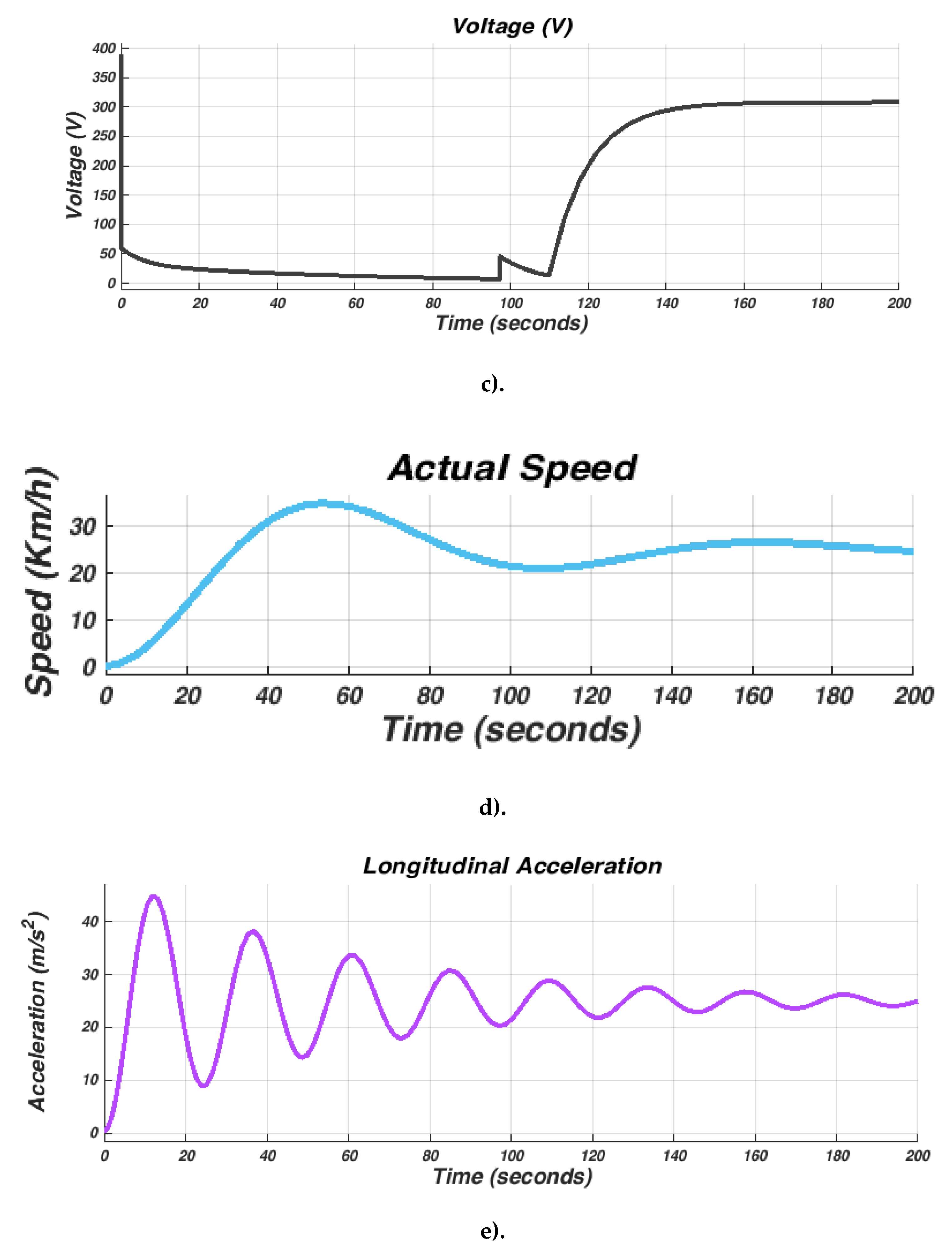
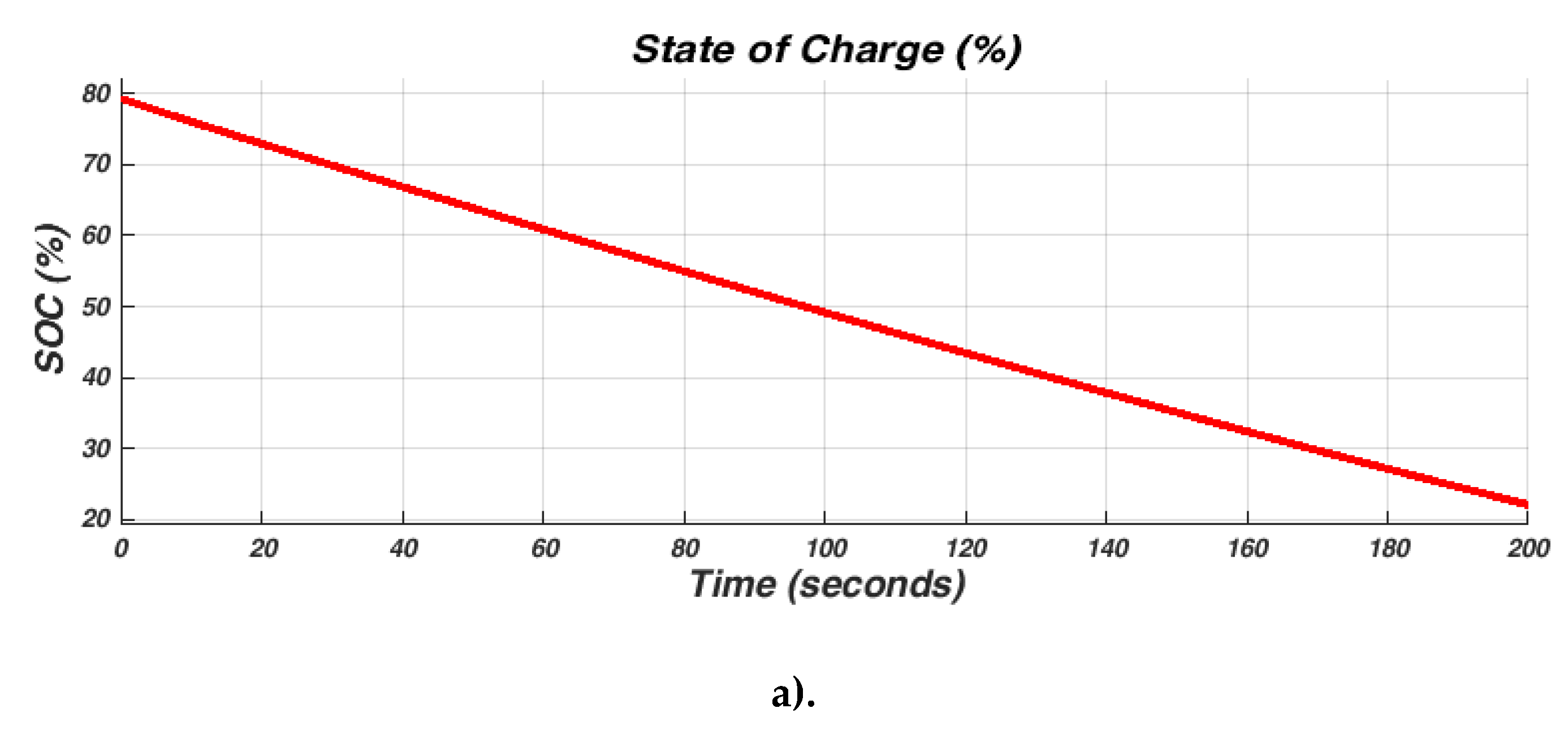
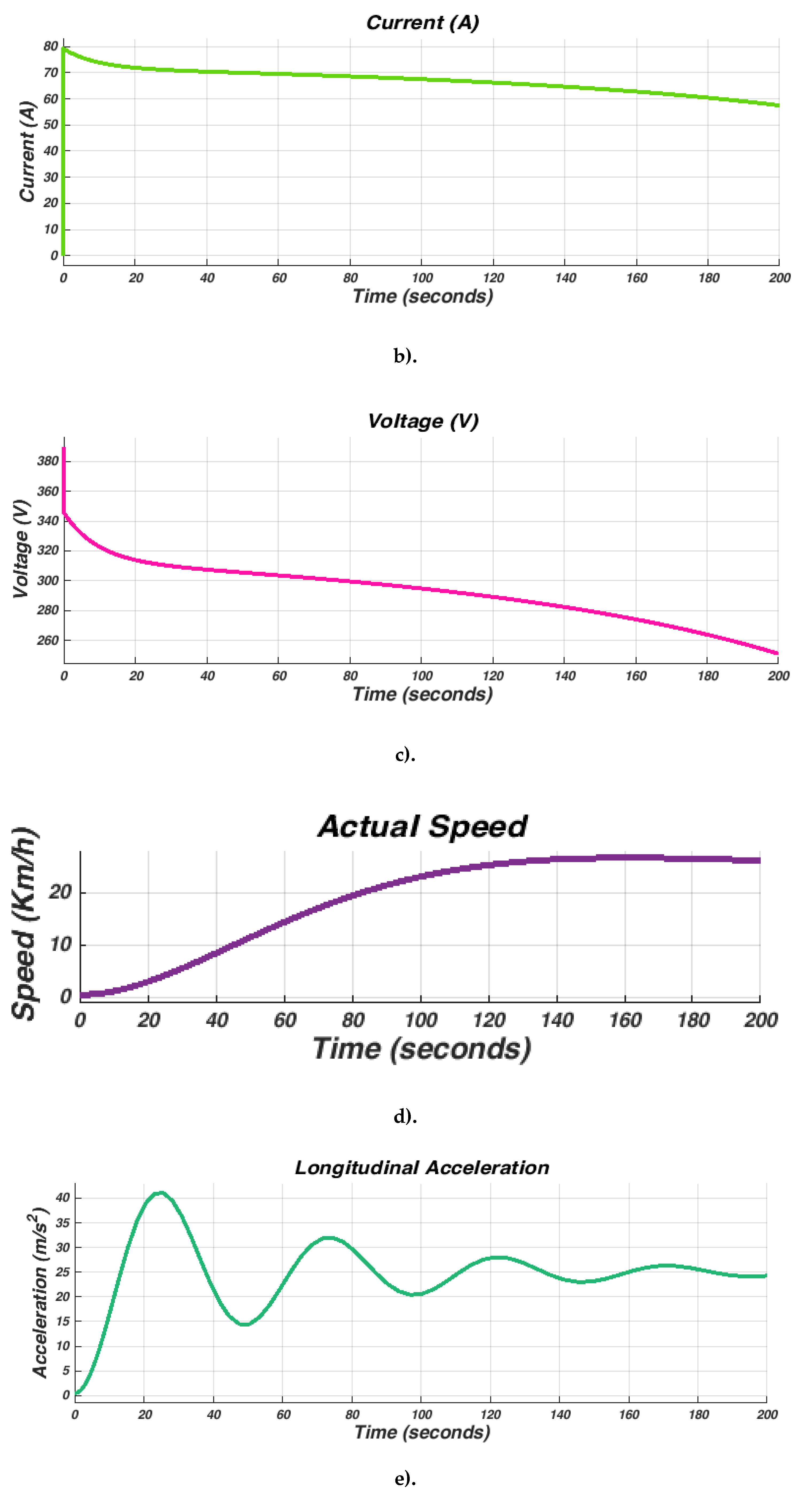
This methodological approach works in a synergistic way, where each component plays a key role in the overall optimization:
The solar panels, optimized by the MPPT algorithm, produce maximum energy that is then efficiently transferred to the batteries and motors thanks to the PWM control. The PI regulator maximizes energy recovery via regenerative braking, exploiting the data collected on driving conditions. The genetic algorithm orchestrates the interaction between all subsystems, identifying in real time the optimal configurations to minimize fuel consumption, maximize autonomy, and reduce emissions. The advantages of this integration logic are:
• The unified method maximizes energy recovery and reduces energy losses at each stage of the process.
• The integrated algorithms (MPPT and genetic) ensure optimal performance in various conditions (climatic, road, etc.).
• The PWM control and the PI regulator improve overall efficiency, thus reducing dependence on fossil fuels.
• The coordination provided by the genetic algorithm reduces the complexity of the systems while increasing their robustness and reliability.

3. Results

Simulating the design of a hybrid electric vehicle is an important phase of the development process, using cutting-edge technologies to create sustainable and efficient transport. Advanced software and computer models are used by engineers and designers to plan, refine, and optimize every aspect of the hybrid electric vehicle architecture. Our simulations take into account complex interactions between parts such as the battery, supercapacitor, electric motor and engine, chassis, and aerodynamics, ensuring seamless integration for the best performance and energy utilization. The longitudinal driver, PWM voltage-controlled, H-bridge, single gear, differential tire, the vehicle body, battery and electric motor, and combustion engine were all included in our simulation to fully represent the behavior of a hybrid electric vehicle. We were able to measure the amount of energy used, the voltage, the current flow, and the energy flow between the electric motor and the combustion engine. We were able to gain important insights into the efficiency, range, and performance of the hybrid electric vehicle (HEV) by running extensive simulations with these interconnected building blocks using MATLAB/SIMULINK 2016 software. This information is crucial to optimize design decisions, improve energy efficiency, and ultimately advance the development of sustainable electric vehicles in our quest for a greener and more environmentally friendly transportation future. To fully understand the underlying principles, validate our results, and ensure their accuracy, we simulated our mid-size, four-wheeled, mild, parallel hybrid vehicle model, the data of which are shown in Table 1.
Figure 4 shows the simulation of a hybrid electric vehicle.
Figure 10. Simulation of the hybrid electric vehicle.
Preprints 146296 g010

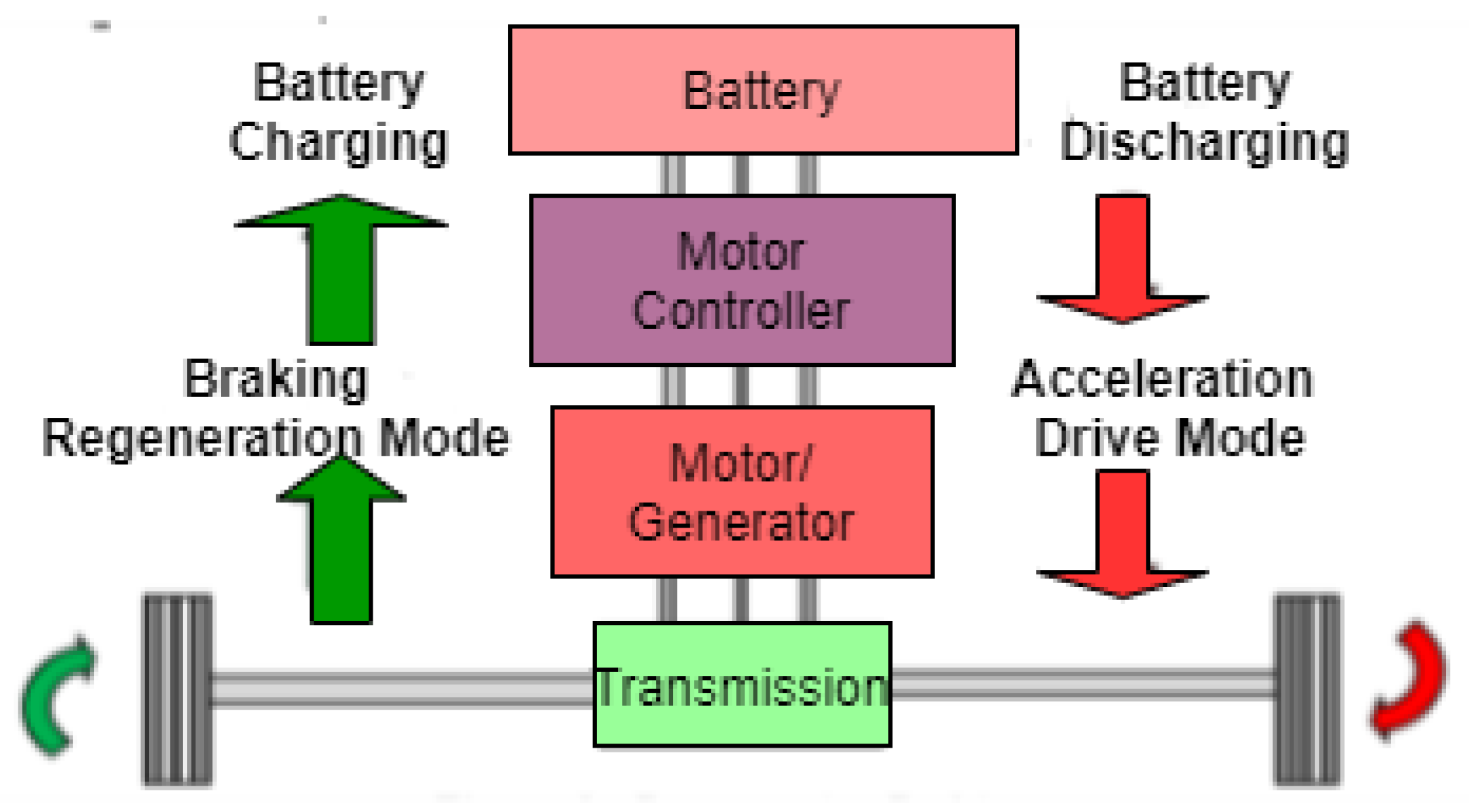
4.3. Regenerative Braking

Our study was comparatively studied, and the simulation results show waveforms with five outputs, with and without optimization with the genetic algorithm (GA). The waveform showed the battery charge level in seconds (represented by waveform a). The voltage and current of the hybrid electric vehicle are represented by waveforms b) and c), its actual speed is indicated by waveform d), while its longitudinal acceleration is indicated by waveform e).
Figure 11. Wave outputs before optimization.
Preprints 146296 g011aPreprints 146296 g011b
Figure 12. Waveform output with optimization with GA.
Preprints 146296 g012aPreprints 146296 g012b

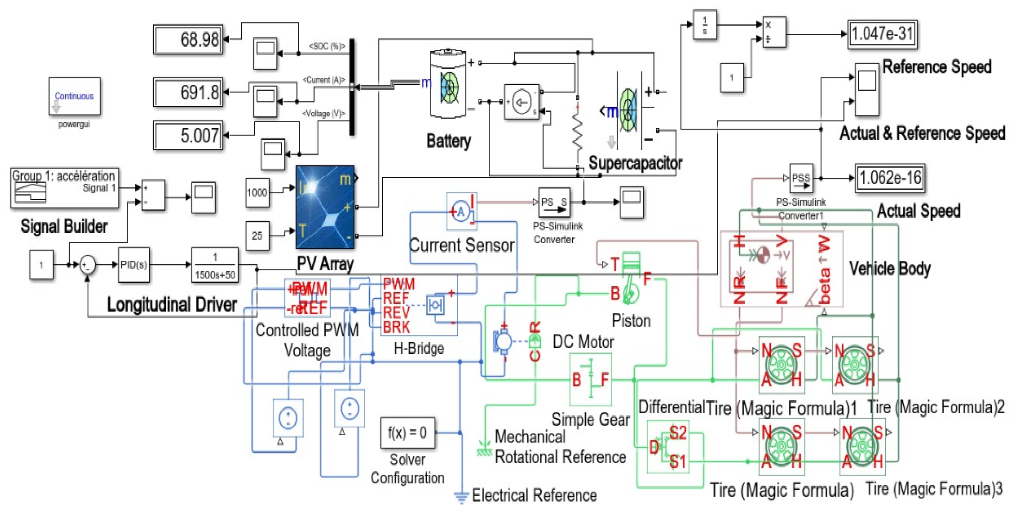
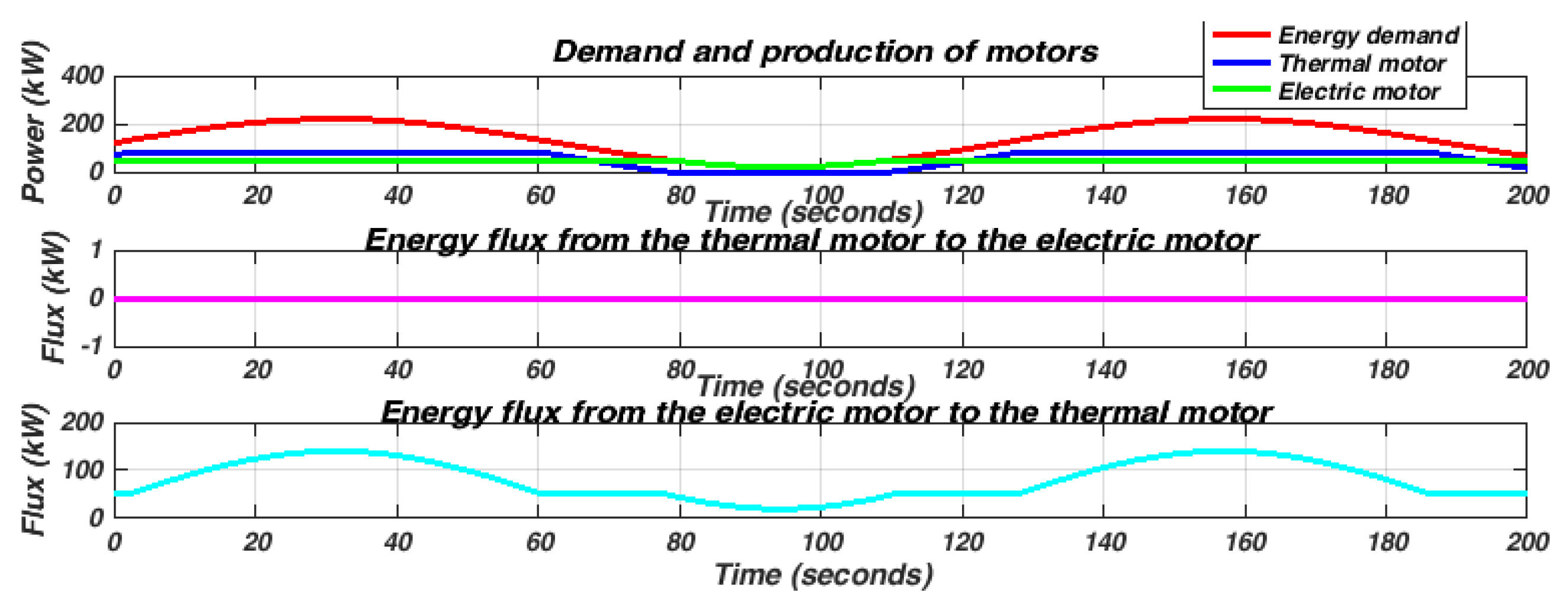
4.4. The Energy Flow Between the Different Motors

The objective of this study is to show how energy flows between the heat engine and the electric motor in our hybrid system. During the acceleration phase, the heat engine provides mechanical energy that is partially converted into electrical energy by the generator (electric motor operating in generator mode). This energy directly powers the battery or supports propulsion via the electric motor. During braking, the kinetic energy is recovered by the electric motor, reconverted into electrical energy, and stored in the battery. Figure 13 below.

4. Discussion

The results of the first simulation demonstrate that from 0 to 35 seconds, as the speed and acceleration increase, both the voltage and the state of charge decrease. And when the speed and acceleration decrease, the voltage and state of charge increase due to regenerative braking, while the current decreases, as shown in Figure 11. We observe that the SOC can drop quickly, leading to deep discharge or overcharging, which affects the battery life. On the current, significant current peaks occur during sudden acceleration or braking. On the voltage level, we note voltage variations due to poorly synchronized energy sources.
The result of the second simulation confirms that, from 0 to 70 seconds and from 170 to 200 seconds, both the voltage and the state of charge decrease as the speed and acceleration increase. And when the speed and the acceleration decrease, both the voltage and the state of charge increase due to regenerative braking, while the current decreases between 150 and 170 seconds, as shown in Figure 12. For the SOC, the AG keeps it in an ideal range, balancing the charge/discharge cycles. This extends the battery life. About the current, the AG adjusts the energy demands, limiting the peak currents and reducing the Joule losses. Regarding the voltage, the GA balances the charge and discharge, maintaining the voltage in an optimal range; this reduces the risk of cell degradation.
With the parameters raised by the GA, the PI controller optimizer allowed us to have the optimal values of the gains after 102 generations under MATLAB (Global Optimization Toolbox); these values are presented in the table below:
Table 2. (Kp, Ki) Values with and without GA.
Controller Gains Without GA With GA
Kp 2.48 3.612
Ki 22.433 0.936
The results of the third simulation highlight the interest of hybrid systems for optimal energy management. The thermal engine provides basic power, while the electric motor offers flexibility and adaptability to variations in demand. Here is an illustration of these flows.
In red, we have the energy supplied by the fuel to the thermal engine. In blue, we have the electrical energy generated and used for propulsion or stored in the battery. In green, we have the energy recovered during braking. We carried out the simulations during an urban cycle. And we collected the following concrete data: 60% of the mechanical energy of the thermal engine directly powers the propulsion. 25% is converted into electrical energy to support the electric motor. 15% of kinetic energy is recovered during braking, increasing overall energy efficiency by 20%.
These results clearly show the interactions between the two motors, with energy transfer optimized to maximize efficiency and reduce losses.

5. Conclusions

This paper proposes an integrated and innovative solution to improve energy efficiency and optimize energy flow management in a parallel hybrid electric vehicle (PHEV) by combining solar panels and regenerative braking. The methodology is based on advanced synchronization of energy sources, combining the maximum power point tracking (MPPT) algorithm, proportional integral (PI) control, genetic algorithms (GA) for optimization, and pulse width modulation (PWM) control. MPPT maximizes the energy harvested from renewable sources and ensures optimal operation of batteries and supercapacitors via a DC-DC converter, while PI control ensures efficient management of the power distribution between thermal and electric sources while stabilizing the DC bus. Genetic algorithms dynamically optimize control parameters, including PI coefficients, to adapt the system to changing driving conditions, and PWM control enables efficient energy conversion, minimizing losses and optimizing motor control. The simulation results confirm the effectiveness of this multidisciplinary approach, highlighting a significant reduction in fuel consumption and an improvement in the overall performance of the PHEV in various driving scenarios. The comparative study, including the evaluation with and without genetic algorithms, demonstrates that the proposed integration strategy contributes substantially to the energy optimization objective. These advances offer promising perspectives for the design of modern energy-efficient hybrid vehicles.

Author Contributions

Christiano Hypolithe Ngi Tonye: Conceptualization, Methodology, Software, Writing - original draft, Validation, Project administration. Frédéric Biya Motto: Methodology, Supervision, Validation. All authors read and approved the final manuscript.

Funding

This research received no external funding.

Data Availability Statement

The original contributions presented in the study are included in the article; further inquiries can be directed to the corresponding author.

Acknowledgments

The authors thank the University of Yaoundé 1 and the laboratory of energies, electrical and electronic systems for their technical support in carrying out this work.

Conflicts of Interest

The authors declare that there is no conflict of interests regarding the publication of this paper.

Abbreviations

MPPT Maximum Power Point Tracking
GA Genetic Algorithm
PI Proportional Integral
PWM Pulse Width Modulation

References

  1. N. Moubayed et F. Chehadi, ENERGY MANAGEMENT IN A PARALLEL HYBRID VEHICLE, vol. IX, janv. 2013.
  2. Y. Arıkuşu, N. Bayhan, et H. Tiryaki, Investigation With Rule-Based Controller of Energy Consumption of Parallel Hybrid Vehicle Model in Different States of Charge, ELECTRICA, vol. 24, p. 183-192, janv. 2024. [CrossRef]
  3. S. Delprat, J. Bernard, et T.-M. Guerra, Stratégie de commande pour véhicule hybride parallèle., janv. 2005.
  4. D. Cabezuelo, J. Andreu, I. Kortabarria, Í. Alegría, et E. Robles, Powertrain systems of electric, hybrid and fuel-cell vehicles: State of the technology, juin 2017, p. 1445-1450. [CrossRef]
  5. S. R. Cikanek et K. E. Bailey, Regenerative braking system for a Hybrid Electric Vehicle, présenté à Proceedings of the American Control Conference, févr. 2002, p. 3129-3134 vol.4. [CrossRef]
  6. S. Hosseini, M. Soleymani, S. Kelouwani, et A. Amamou, Energy Recovery and Energy Harvesting in Electric and Fuel Cell Vehicles, a Review of Recent Advances, IEEE Access, vol. PP, p. 1-1, janv. 2023. [CrossRef]
  7. H. Seok, B. Han, S.-H. Kim, J.-G. Lee, et M. Kim, Rippleless resonant boost converter for fuel-cell power conditioning systems, in 2018 IEEE Applied Power Electronics Conference and Exposition (APEC), mars 2018, p. 653-658. [CrossRef]
  8. SA. Goel, V. Rajput, S. Bajaj, R. Mittal, A. Dube, et Ruchika, Solar hybrid electric vehicle — A green vehicle for future impulse, 2016 3rd Int. Conf. Comput. Sustain. Glob. Dev. INDIACom, mars 2016.
  9. J. Merin et al., Hybrid MPPT Solar-Wind Electric Vehicle With Automatic Battery Switching, nov. 2018, p. 1-6. [CrossRef]
  10. B. Prasad, T. Devi, V. Nookaraju, D. Sai, et P. Kumar, Modelling and Simulation of Solar Powered Hybrid Electric Vehicle, avr. 2023, p. 1-5. [CrossRef]
  11. G. Rizzo, I. Arsie, M. Sorrentino, G. Rizzo, I. Arsie, et M. Sorrentino, Hybrid Solar Vehicles, in Solar Collectors and Panels, Theory and Applications, IntechOpen, 2010. [CrossRef]
  12. K. Mohan, S. Sankaranarayanan, S. S. D. Prasad, V. Sivasubramaniam, et V. Sairam, Solar powered Hybrid vehicle, IOP Conf. Ser. Mater. Sci. Eng., vol. 390, no 1, p. 012102, juill. 2018. [CrossRef]
  13. X. Ning, J. Wang, Y. Yin, J. Shangguan, N. Bao, et N. Li, Regenerative Braking Algorithm for Parallel Hydraulic Hybrid Vehicles Based on Fuzzy Q-Learning, Energies, vol. 16, p. 1895, févr. 2023. [CrossRef]
  14. P. Millet et J.-C. Heudin, Comparison between Three Heuristic Algorithms to Repair a Large-Scale MIMD Computer, in Evolvable Systems: From Biology to Hardware, J. Miller, A. Thompson, P. Thomson, et T. C. Fogarty, Éd., Berlin, Heidelberg: Springer, 2000, p. 145-154. [CrossRef]
  15. R. Gianfranco et al., A prototype car converted to solar hybrid: project advances and road tests, IFAC-Pap., vol. 55, no 24, p. 329-334, janv. 2022. [CrossRef]
  16. M. C. P. Selvan, S. R. Madara, S. R. Pillai, et R. Vandanapu, Solar hybrid vehicles for environmental protection, in 2018 Advances in Science and Engineering Technology International Conferences (ASET), févr. 2018, p. 1-6. [CrossRef]
  17. F. A. Tiano, G. Rizzo, G. De Feo, et S. Landolfi, Converting a Conventional Car into a Hybrid Solar Vehicle: a LCA Approach, IFAC-Pap., vol. 51, no 31, p. 188-194, janv. 2018. [CrossRef]
  18. A. B. Sankar et R. Seyezhai, Simulation and Implementation of Solar Powered Electric Vehicle, Circuits Syst., vol. 7, no 6, Art. no 6, mai 2016. [CrossRef]
  19. C. Desai et S. S. Williamson, Optimal design of a parallel Hybrid Electric Vehicle using multi-objective genetic algorithms, in 2009 IEEE Vehicle Power and Propulsion Conference, sept. 2009, p. 871-876. [CrossRef]
  20. W. Li, G. Xu, Z. Wang, et Y. Xu, A Hybrid Controller Design For Parallel Hybrid Electric Vehicle, in 2007 IEEE International Conference on Integration Technology, mars 2007, p. 450-454. [CrossRef]
  21. P. G. Anselma et al., Comparing Parallel Hybrid Electric Vehicle Powertrains for Real-world Driving, juill. 2019. [CrossRef]
  22. S. Pittet, Modélisation physique d’un transistor de puissance IGBT: traînée en tension à l’enclenchement, janv. 2005. [CrossRef]
  23. P. Ning, T. Yuan, Y. Kang, C. Han, et L. Li, Review of Si IGBT and SiC MOSFET based on hybrid switch, Chin. J. Electr. Eng., vol. 5, p. 20-29, sept. 2019. [CrossRef]
  24. D. Lanzarotto, M. Marchesoni, M. Passalacqua, A. P. Prato, et M. Repetto, Overview of different hybrid vehicle architectures, IFAC-Pap., vol. 51, no 9, p. 218-222, janv. 2018. [CrossRef]
  25. J. Jaguemont, L. Boulon, et Y. Dubé, A comprehensive review of lithium-ion batteries used in hybrid and electric vehicles at cold temperatures, Appl. Energy, vol. 164, p. 99-114, févr. 2016. [CrossRef]
  26. RC aircraft/drone/UAV battery | Products. Accessed: December 15, 2024. [Online]. Available at: https://www.pdbattery.com/rc-aircraft-battery.html.
  27. S. Bolognani, M. Morandin, S. Calligaro, R. Petrella, et A. Pevere, « Bidirectional PMSM drive employing a three level ANPC inverter and a multi-phase interleaved DC/DC converter for hybrid electric vehicles, présenté à Conference Proceedings - IEEE Applied Power Electronics Conference and Exposition - APEC, mars 2014, p. 818-825. [CrossRef]
  28. F. Mocera, A Model-Based Design Approach for a Parallel Hybrid Electric Tractor Energy Management Strategy Using Hardware in the Loop Technique, Vehicles, vol. 3, p. 1-19, déc. 2020. [CrossRef]
  29. M. Morandin, S. Bolognani, et A. Faggion, Active Torque Damping for an ICE-based Domestic CHP System with an SPM Machine Drive, IEEE Trans. Ind. Appl., vol. 51, p. 1-1, juill. 2015. [CrossRef]
  30. K. Welke, M. Ochs, et H.-J. Schmidt-Brücken, Single Shaft Parallel Hybrid Drive System, SAE International, Warrendale, PA, SAE Technical Paper 970286, févr. 1997. [CrossRef]
  31. Hybrid Solar Inverter SAJ FOR MOTOR VEHICLES. https://tienda-solar.es - Recherche Google. Accessed: July 15, 2024.
  32. Hybrid inverter | Solar-battery.com, Battery-Solar.Accessed: July 15, 2024. [Online]. Available at: https://www.batterie-solaire.com/263-indicateur-hybride.
  33. N. R. Varma, K. C. Reddy, G. Dhasharatha, V. Manohar, K. K. Kumar, et V. P. Kumar, Hybrid Electrical Vehicle Design by Using Solar and Battery Sources, E3S Web Conf., vol. 472, p. 01006, 2024. [CrossRef]
  34. M. Waseem, A. Sherwani, et M. Suhaib, Integration of solar energy in electrical, hybrid, autonomous vehicles: a technological review, SN Appl. Sci., vol. 1, p. 1459, nov. 2019. [CrossRef]
  35. G. R. Chandra Mouli, P. Bauer, et M. Zeman, System design for a solar powered electric vehicle charging station for workplaces, Appl. Energy, vol. 168, p. 434-443, avr. 2016. [CrossRef]
  36. G. Rizzo, F. A. Tiano, V. Mariani, et M. Marino, Optimal Modulation of Regenerative Braking in Through-The-Road Hybridized Vehicles, Energies, vol. 14, no 20, Art. no 20, janv. 2021. [CrossRef]
  37. Adaptation in Natural and Artificial Systems, MIT Press. Accessed: July 15, 2024. [Online]. Available at: https://mitpress.mit.edu/9780262581110/adaptation-in-natural-and-artificial-systems/.
  38. D. B. Fogel, Artificial Intelligence through Simulated Evolution, IEEE, 2009. [CrossRef]
  39. H.-P. Schwefel, Numerical Optimization of Computer Models, vol. 33. 1981. [CrossRef]
Figure 1. Block diagram of Hybrid Electric Vehicle.
Preprints 146296 g001
Figure 2. Serie architecture.
Preprints 146296 g002
Figure 13. Variation of energy flows.
Preprints 146296 g013
Table 1. Parameters for the studied parallel hybrid electric vehicle.
Parameters Values
Rolling resistance coefficient C d 0.01
Air density ρ (kg/ m 2 ) 1.3
Vehicle mass m (kg) 1500
Gravitational acceleration g (m/ s 2 ) 9.8
Frontal area A f ( m 2 ) 2.8
Aerodynamic friction coefficient C f 0.35
Auxiliary system P a u x (kW) 0.5
Vehicle inertia (Kg.m-2) 2630
Disclaimer/Publisher’s Note: The statements, opinions and data contained in all publications are solely those of the individual author(s) and contributor(s) and not of MDPI and/or the editor(s). MDPI and/or the editor(s) disclaim responsibility for any injury to people or property resulting from any ideas, methods, instructions or products referred to in the content.
Copyright: This open access article is published under a Creative Commons CC BY 4.0 license, which permit the free download, distribution, and reuse, provided that the author and preprint are cited in any reuse.
Prerpints.org logo

Preprints.org is a free preprint server supported by MDPI in Basel, Switzerland.

Subscribe

Disclaimer

Terms of Use

Privacy Policy

Privacy Settings

© 2025 MDPI (Basel, Switzerland) unless otherwise stated