Submitted:
08 January 2025
Posted:
09 January 2025
You are already at the latest version
Abstract
This work presents a recently patented method of inertial electrostatic confinement (IEC) fusion called the Nuclear Electromagnetic Shaping Accelerator Reactor (NESAR) that addresses all of the major failure problems with currently known methods of IEC fusion. A brief background of previous IEC methods that generate a negative potential well to accelerate ions for fusion will be reviewed and compared to the NESAR method of magnetic confinement. In addition, a direct comparison will be presented between the NESAR and the tokamak method of fusion. The NESAR method of fusion obtains the plasma oscillation and compression capabilities of a tokamak without producing the catastrophic magnetic reconnection disruptions that currently plague tokamaks. Since the NESAR can oscillate charged particles comparable to the tokamak, this work will briefly review the history of the tokamak, how sawtooth magnetic reconnection occurs, and how the NESAR precludes the occurrence of magnetic reconnection.
Keywords:
fusion
; magnetic reconnection
; sawtooth
; tokamak
; Inertial Electrostatic Confinement (IEC)
; magnetic confinement
; polywell
; charged particle
1. Introduction
The confinement of electrons or dense ionized gases (i.e., plasma) is a necessary step in several processes currently researched for nuclear fusion; especially in the field of inertial electrostatic confinement (IEC) fusion. The confinement of electrons or dense ionized gases is performed by a confinement device (also referred to as a confinement apparatus); which uses magnetic fields to manipulate the trajectories and confinement of electrons to form a negative potential well (i.e., virtual cathode). Once a negative potential well is established, ions are injected within the vacuum chamber and are accelerated towards the negative potential well to fuse. Current methods in this field have major issues with electron losses, uniform plasma distribution, fusion rates, and electron recirculation/circulation which are critical failure issues that have restricted IEC methods in producing enough sustainable fusion reactions to surpass the breakeven point (i.e., the output energy produced by fusion reactions equaling the input energy needed for the system). To design an IEC fusion device that generates enough sustainable fusion reactions to surpass the breakeven point; it is essential to address these four failure issues to make further advancements in the field.
The Nuclear Electromagnetic Shaping Accelerator Reactor (NESAR) is a patented confinement method that is a simple approach that addresses almost all of the major failure issues that currently plague IEC methods towards sustainable fusion.1 This paper will briefly cover previous IEC methods by Dr. William C. Elmore and Dr. Robert Bussard, and the failure issues that these previous methods of IEC fusion encountered. This paper will then cover the major issues found with these currently known methods of IEC fusion and how they are amended by the NESAR focusing on the capabilities of confinement, ion distribution, and fusion rate.
Lastly, the NESAR method of fusion will be directly compared to the tokamak; as the NESAR combines both of the major components of IEC and tokamak methods of confinement. Due to the unique design of the NESAR, it has the capability to oscillate and compress confined plasmas without producing the catastrophic magnetic reconnection disruptions that currently plague the tokamak. Due to these common features in both the NESAR and tokamak, this work will briefly review the history of the tokamak, how sawtooth magnetic reconnection occurs, and how the NESAR precludes the occurrence of magnetic reconnection.
2. Background (Review of Literature of IEC Method of Fusion)
Early work in this field by Dr. William C. Elmore is depicted in Figure 1. This depiction demonstrates how emitted electrons from the inner surface of a spherical shell, 300, accelerate toward a grid of higher electric potential, 310. The electrons that accelerate towards the grid will pass through the grid and converge radially to a central region, 330, to form an electron cloud that is known as a negative potential well.4
Once a negative potential well is established, ions are injected into the chamber to accelerate towards the electron cloud 330 to perpetuate the fusion process. The Elmore design, however, provided no means of inhibiting electron loss at the sphere surface.
Building on this work, Dr. Robert W. Bussard proposed using a confinement apparatus made of a set of conductive coils arranged as a polyhedron generating set of magnetic fields to confine the electrons in the negative potential well, as shown in Figure 2 from Bussard’s patent, reproduced below:
In Bussard’s design, electrons were injected through the “cusps” (i.e., boundaries between the magnetic fields) into the confinement apparatus where they were retained by the magnetic fields; creating a negative well potential. Ions then dropped into the confinement apparatus to accelerate towards the negative well potential to allow the fusion process to occur.
Research into the Polywell design, however, by Dr. Joel Rogers and Dr. Jaeyoung Park, revealed major electron losses at the cusps between the magnetic fields; which is the primary failure issue for the Polywell. For example, the below patent image, Figure 3, from Park, depicts the major areas where electrons escape from the confinement apparatus occurs. These areas of escape are highlighted in red.5
As previously stated, electrons escape from the confines of the polywell at the magnetic cusps. Depicted in Figure 4 is a magnified view of a magnetic cusp showing how an electron, depicted by a red arrow, escapes the confines of the polywell. In this figure, the electron is depicted as a red arrow. When an electron’s trajectory is parallel enough to the cusp it is able to easily escape. In addition, when the confinement pressure within the confines of the polywell are low, the magnetic cusps are more effective at redirecting the electrons back into the confines of the polywell; but as pressure builds within the confinement apparatus the system becomes less efficient at containing the electrons. When the pressure increases within the magnetic confines of the polywell, the magnetic cusps are forced to widen. It is this widening at the cusps that allows excess amounts of electrons to escape the system.
In addition, the polywell’s lack of uniformity, by having the highest density of electrons located at the cusps, 106, greatly diminished the fusion rate of the polywell.6 The polywell has 14 of these cusps, 106, generating 14 separate locations where electrons are concentrated. The space between these cusps are where the electron densities are the greatest, which is depicted in the left image in Figure 5.6 , does not support the necessary density and relative trajectory for sustainable fusion. These areas, where electrons are concentrated in the polywell, cause injected ions to accelerate in multiple locations, resulting in a low fusion rate and a lower density of confined ions, which is depicted by the right image in FIGURE 5.6 In addition, since all of the confined electrons have independent trajectories, the electrons within the confinement are not distributed uniformly, further contributing to a low rate of fusion by causing ions to accelerate to various locations within the confines.
3. Analysis (Solution for IEC Method of Fusion)
The Nuclear Electromagnetic Shaping Accelerator Reactor (NESAR) introduces at least three separate innovations over the polywell to better confine, uniformly distribute, and circulate electrons within the confinement apparatus.1 The first innovation has the confinement apparatus designed with more coils, in comparison to the polywell, to more evenly distribute the pressure created by the particles confined within the confinement apparatus. The magnetic coils are sized and arranged in a manner to closer resemble the shape of a rounded sphere. If all of the contiguous magnetic coils that make up the confinement apparatus are the same size, more dimension variances will be present in the distribution of the magnetic cusps needed for the effective confinement of electrons. To alleviate this issue a pentafoil pattern comprised of a set of five larger conductive coils that surround a smaller conductive coil is used to form the spherical shape of the confinement apparatus, as shown in Figure 6. This type of configuration should more evenly distribute the pressure created by the particles confined within the confinement apparatus, reducing the escape of electrons.
The second and most important innovation, the NESAR obtains a set of magnetic coils angled off-center relative to a solitary location (i.e. single relative center point (SRCP) 601), which greatly improves the confinement capabilities of the system when compared to the previous methods of IEC fusion. Angling the magnetic coils in this manner allows for the magnetic fields that confine the electrons to overlap upon one another while the collective confinement of electrons within the confinement apparatus to spherically rotate relative to the SRCP; resulting in the improvement of the confinement apparatus’ ability to magnetically confine electrons and accelerate injected ions more efficiently in improving the system’s rate of fusion. The number of magnetic coils angled off-center and the degree of angle that they obtain can vary to optimize electron confinement and fusion rates. The left image in FIGURE 7 is a general depiction of how angling the magnetic coils allow for confined electrons to rotate within the confinement apparatus.1 The more evenly distributed confinement of electrons will resemble a rotating ball where the electron density decreases when approaching closer to the center as seen in the right diagram in Figure 7.
The effects of introducing a rotation to the negative potential well allow for the confinement of electrons to travel in a collective path that is more perpendicular to the magnetic cusps. This more perpendicular path reduces the possibility of electrons escaping through the magnetic cusps of the confinement apparatus. In addition, the overlapping of the magnetic fields from the angled magnetic coils from the confinement apparatus restricts the escape of electrons that are part of the collective rotation. Essentially, the only way that electrons can escape the magnetic cusps of the confinement apparatus, if angled appropriately, is by obtaining a trajectory that would be inconsistent and contrary to the rotational collective; which would be minimal. Thus, rather than escaping in the manner shown in Figure 4, the electrons traveling in this more perpendicular path are deflected away from the cusps as shown in Figure 8.
In addition, the confined charged particles being pushed more perpendicular to the magnetic cusps and rotating within the confinement apparatus creates a dominant magnetic field within the confines by the rotating charged particles. Since magnetic fields do not cross each other, they merely push against one another and overlap. This means that the magnetic cusps of the angled toroidal magnetic fields that are layered upon each other while pushing a rotation upon the confined charged particles will reduce in size as the magnetic field of the confined charged particles increase. As the magnetic field of the confined particles increases it pushes outward and forces the layered magnetic cusps to close. Thus, increasing the confinement apparatus’ capability in trapping charged particles. Generating a dominant magnetic field from the confined charged particles within the confinement apparatus, which is something the polywell was never capable of producing because the confinement of charged particles had no common relative trajectories. In the polywell, every confined electron obtained independent loop fields that would, for the most part, cancel each other out as a system. Figure 9. Depicts how the increasing magnetic field of the confines pushes the cusps upon each other to improve confinement capability.
This spherical circulation of electrons promotes a solitary location where the negative potential well is maximized due to the confined electrons electrostatically interacting at the SRCP; creating a solitary location where the majority of the injected ions will initially fuse. In addition, rotating the confinement of electrons in this manner also promotes a more even density distribution of the confined charged particles. Obtaining a more uniform confinement in this manner allows for a substantially improved yield in fusion rates in comparison to the polywell by allowing injected ions to accelerate to a more centralized location and permitting ions that do not initially fuse to be recirculated within the confinement apparatus to continue the fusion process. Figure 10 is a depiction of a maximized negative well singularity being generated by rotating electrons relatively electrostatically interacting at a solitary location.
The third innovation is the NESAR’s ability to physically rotate the confinement apparatus in a direction opposite to the electrons that are in an initial rotational direction. Even though the device should operate efficiently without the confinement apparatus rotating in an opposing second rotational direction; this added feature should, to some extent, increase the system’s capabilities by improving the confinement apparatus’ ability to shape a more spherical confinement that is also more evenly distributed in electron density over time.
The apparatus’ ability to enable a physical rotation to the confinement apparatus is depicted in Figure 11. The apparatus’s ability to rotate is accomplished by affixing two hollow supports, 304 and 305, to the opposite ends of the confinement apparatus that obtain rotors, 301 and 307, at the end of them. The confinement apparatus is supported by two bearings, 303 and 306, that are coupled at the walls of the primary chamber that envelope the confinement apparatus and the two hollow supports that extend into two ancillary chambers. The two rotors at the ends of the hollow supports are then encapsulated within the same ancillary chambers that are encompassed within surrounding stators. These stators are then energized to induce movement upon the rotors. In the image below, the chambers are outlined in red to emphasize how the confinement apparatus is coupled to the system. In the second image, the rotation of the confinement apparatus opposing the rotation of the confined charged particles, 801, is depicted by the number 802.
As for energizing the confinement apparatus while it is in rotation, a novel method of having a direct current transferred throughout the confinement apparatus has also been implemented, if rotating the confinement apparatus is desired. A current is passed from one of two brushes that make contact with the commutator, 302, that is coupled to the hollow support, 304. The current is then fed to the conductive coils throughout the confinement apparatus from within the hollow support, and is then returned back to the commutator from within the same hollow support where the returning current exists through the second brush in contact with the same commutator.
To emphasize, the direct current transferring through the brushes, commutator, hollow support, and confinement apparatus is not what generates rotation upon the confinement apparatus; which are the common essential components that are normally used for generating movement in the rotor of a DC motor. In the NESAR, these components are only used to energize the conductive coils of the confinement apparatus to generate the needed magnetic fields to confine charged particles.
In conclusion, the NESAR directly addresses all of the major concerns and issues that have plagued previous methods of IEC fusion.7 If future simulations can validate even half of the possible improvements claimed by the NESAR method of confinement; the possibility exists for this method to surpass previous methods of IEC fusion and surpass the breakeven boundary. In essence, this invention represents a positive step forward in at least confining electrons to generate a negative potential well in IEC devices.
4. Background (Review of Literature of Tokamak Method of Fusion)
Currently, the most researched and popular approach toward sustainable fusion is the tokamak method of magnetic confinement. The conception of this method of fusion has been around for almost seventy years. The first tokamaks were secretly developed by the Soviet Union in the late 1950s, and were declassified to the public by the mid-1960s. The same failure issues that we observe today with tokamaks were first documented in 1974, and these same failures were confirmed to be uncorrectable by the mid-1990s. The most well-known and largest tokamak research project is the International Thermonuclear Experimental Reactor (ITER). To date the accumulated cost to fund ITER has come to more than 30 billion dollars; and will not be able to be fully tested until 2035, if it works.8
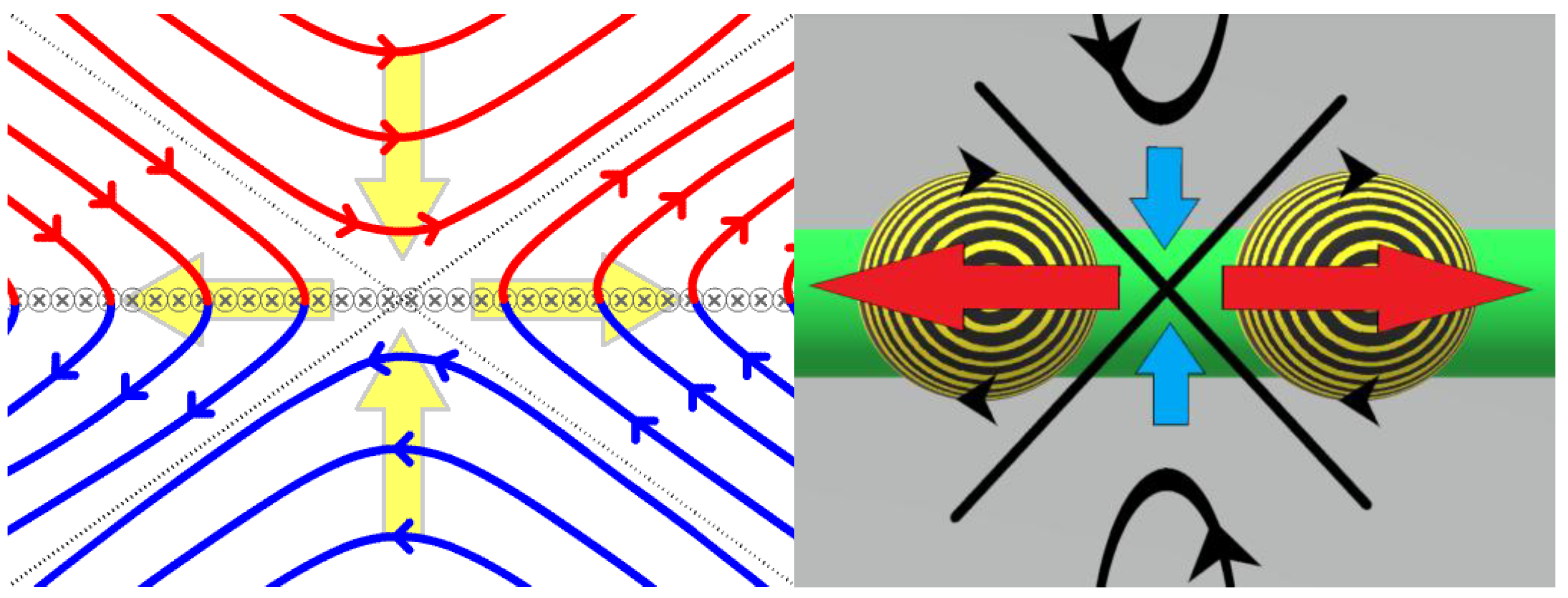
As previously alluded to in the prior paragraph, it has almost been fifty years since researchers were first aware of the greatest failure issue with tokamaks. The main failure issue is that tokamaks generate catastrophic magnetic reconnection events that are powerful enough to overwhelm and disrupt the confinement system. Magnetic reconnection is the physical process occurring in highly conducting plasmas in which the magnetic topology is rearranged and magnetic energy is converted to kinetic energy, thermal energy, and particle acceleration. Figure 12 is a Parker-Sweet reconnection diagram, that depicts plasmas with oppositely directed magnetic field lines in highly conductive plasmas flowing towards each other forming two newly connected field lines that have a plasma outflow.9 The image is depicting a plasms magnetic field in red, from the top, being pushed towards an opposing plasma’s magnetic field in blue, from the bottom. As these fields get closer to each other, they form newly connected field lines that expel massive disruptive energies perpendicularly outward from the inflow from the top and bottom. This plasma inflow and outflow relationship is emphasized by the yellow arrows. This is a very simple two-dimensional description of magnetic reconnection.
Even though tokamaks are unsuccessful due to magnetic reconnection failure; experts have a general idea of how reconnection events occur. The reconnection failure in tokamaks is called a sawtooth reconnection and it is mainly caused by the design of the tokamak incorporating poloidal fields. The purpose of the poloidal fields in tokamaks is to compress and assist the confined plasma in obtaining a helical pattern as it travels through the tokamak. While obtaining this helical trajectory, the poloidal fields compress the confined plasma towards the relative cross-sectional center of the toroidal shaped plasma. Sadly, incorporating the feature of a poloidal field seems like a sound enhancement, but this addition is the main cause for sawtooth reconnections in tokamaks.
Sawtooth reconnection originates from an induced field, called a magnetic island, being generated from varying energy states of the confined charged particles within the confines of the tokamak. The way sawtooth reconnection occurs is depicted in Figure 13; the magnetic island is in yellow. This reconnection occurs when the opposing induced current’s field, magnetic island, is pinched and severed in between the field of the main current of confined charged particles and the tokamaks poloidal fields. This happens because the tokamak’s poloidal field currents run parallel to the main current of confined charged particles. Even though the poloidal fields are compressing the confinement of the charged particles to the center of the main current, the main current itself is being pulled towards the poloidal fields, as parallel currents attract towards one another. As a tokamak increases in its confinement of charged particles; the induced current’s field gets pinched between the field of the main current of charged particles being pulled towards the fields of the poloidal currents that are affixed to the outside of the confinement apparatus. This pinching of the induced field causes an explosive surge of kinetic and thermal energy that causes massive disruptions in the tokamak confinement. Figure 13 depicts this sawtooth failure. The opposing induced current being created is depicted in Figure 13 on the left in yellow. On the right of Figure 13, the main current’s field, in orange, is being pulled towards the parallel running poloidal currents, in green; pinching the induced current’s field, in yellow.
5. Analysis (Solution for Tokamak’s Issues with Magnetic Reconnection)
All magnetic fields are made of photons and every field line has a distinctive property that makes them different from each other. This distinctiveness for each field line is what keeps them from merging. Magnetic reconnection occurs when closed-loop fields are forced to collapse upon themselves, but more specifically by forcing a field line with the exact same density and characteristics to interact and merge upon itself. Magnetic field lines will always seek the path of least resistance between opposite magnetic poles. So, when the conditions are met where a field line can interact with itself and shorten the closed-loop distance, it will. Three or more parallel running currents that are increasing in their field strengths are required to generate an increased attractive force amongst them, thus having the potential to pinch and sever a closed-loop field. Figure 14 depicts this interaction, by depicting how these parallel currents force a closed-loop’s most centralized field lines with the exact same density to interact with each other and reconnect. In the depiction in Figure 14, the different densities of the field lines are depicted by different widths.
As a prideful West Virginian, it is easiest for me to explain magnetic reconnection by relating it to coal locomotives transiting on railroads. I grew up about 150 yards away from the railroad tracks, and daily I would see powerful locomotives filled with coal rolling through our borough hills. Because of being raised in such close proximity to West Virginia’s lifeblood, it is probably why it was natural for me to associate magnetic reconnection with transiting coal trains. Imagine that each field line is a flexible rubber train track. Each flexible track has a different width and is meant to represent an individual closed-loop. The wider and shorter tracks are closer to the dipole source than the thinner and longer tracks. This means that only a specific size locomotive can ride on each track. If each locomotive is pulling a line of hopper cars full of coal that is the length of their field lines, the amount of weight carried by each train would equal the same amount of weight on each track. This weight represents the field strength. Since each track is made specifically for each train they do not merge or cross, but when the same size track is forced upon itself; a train is able to fit on the newly found track and take the shortcut towards the dipole which is the path of less resistance. This new path breaks the track into two separate looped tracks that are carrying less weight than the other surrounding tracks. So, the lighter, weaker, track that is still attached to the perfectly balanced dipole system; must be compensated to operate within the law of conservation of energy. This means that a dipole system in plasma undergoing magnetic reconnection will rapidly shift and convert to balance for the loss of weight, magnetic strength, into an energy that is equivalent to the weight of the reconnected track that is detached from the dipole system. This converted energy then ejects the detached track away from the dipole system. Of course, this is a simple way to think about how magnetic reconnection is initiated, but reconnection is not a simple two-dimension interaction, in reality, it is more like a photonic bubble being severed and reconnected, which is why there must be at least three areas of focused attraction to sever a closed-loop field at a given location.
In revisiting the Parker-Sweet reconnection diagram in Figure 12, it depicts how plasma inflow and plasma outflow regions with the field directions produce magnetic reconnection occurrences. When this diagram is compared to the resulting diagram in Figure 14, it is obvious to see how these two depictions align in depicting the same magnetic reconnection event. Being able to align these depictions of magnetic reconnects by using attractive parallel running currents to illustrate this phenomenon; displays how this occurrence happens in tokamaks.
Figure 15.
(left) This is the cross-section of the four magnetic domains undergoing Parker-Sweet reconnection from FIGURE 12; (right) the right image in FIGURE 14 depicting how it replicates the exact depiction of magnetic reconnection from the Parker-Sweet diagram.
Figure 15.
(left) This is the cross-section of the four magnetic domains undergoing Parker-Sweet reconnection from FIGURE 12; (right) the right image in FIGURE 14 depicting how it replicates the exact depiction of magnetic reconnection from the Parker-Sweet diagram.
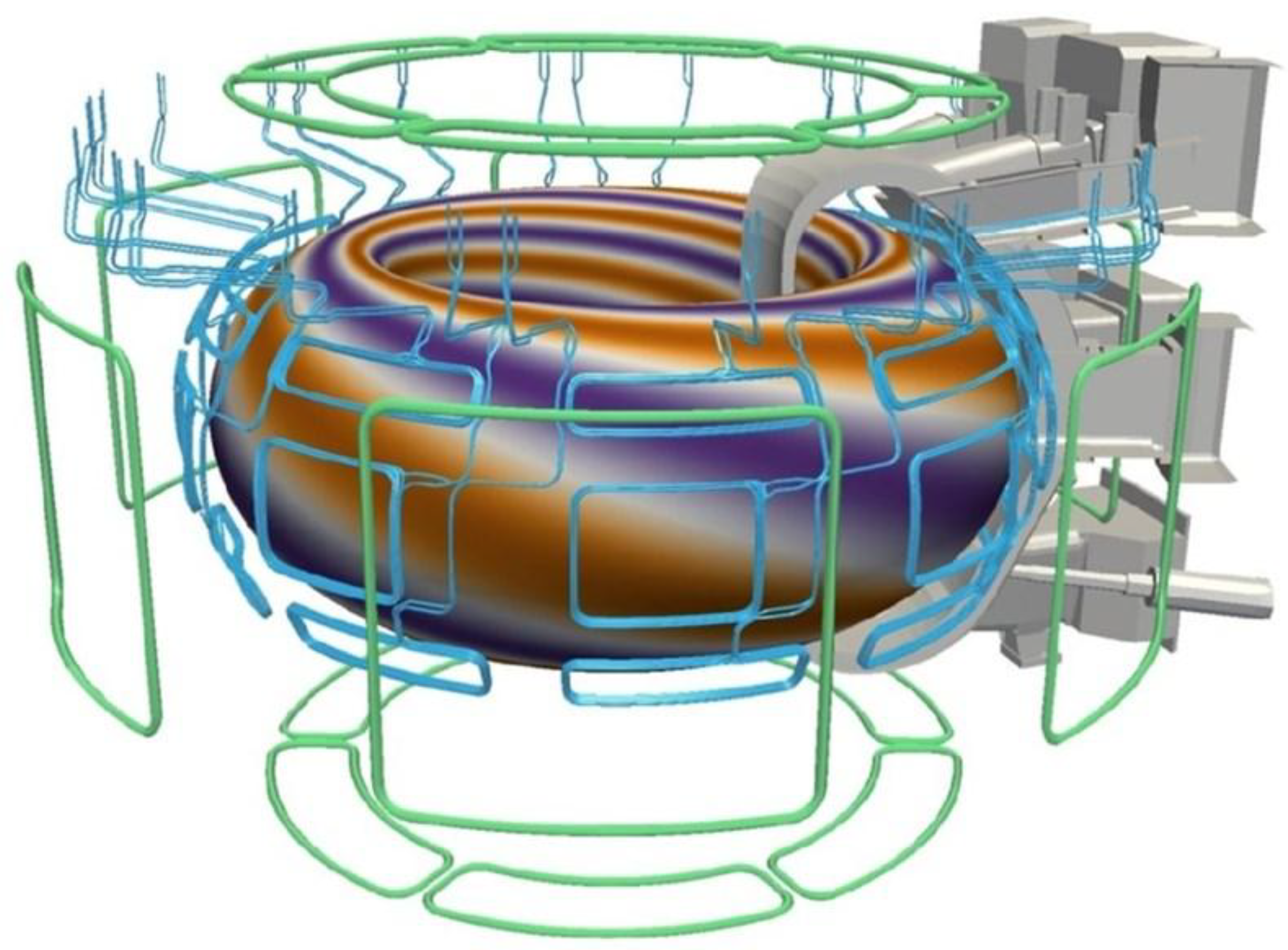
Due to magnetic reconnection failures in the original designs of the tokamaks, it is no wonder that two extra magnetic systems have been added to tokamak systems, like ITER, in the hopes of possibly correcting the tokamak’s natural tendency to magnetically reconnect mainly due to the system’s poloidal fields. The two additional magnetic systems included in the tokamak system to address magnetic reconnection failures are the Correction Coils and Edge-Localization Modes (ELM) magnets.10 These two systems require complicated sensors and analytical systems to monitor and control the confinement’s efficiency. Even though these additional systems may improve the duration of time that plasmas within tokamaks are able to stabilize, many experts are very skeptical if Correction Coils and ELMs will be enough to allow tokamaks to be stable long enough to be used for fusion energy commercially. It is stated by those involved with ITER that Correction Coils are needed to compensate for field errors and ELM magnets are specifically used to massage the confined plasma. 10 To simplify it, the combined purpose of these two magnetic systems is to push the field of the confined toroidal plasma current away from the wall of the vacuum vessel, resisting the tokamak’s natural tendency to pinch induced currents that cause magnetic reconnection. In Figure 16, the Correction Coils are depicted in green, and the ELMs are depicted in blue.
The magnetic reconnection issues that hinder the tokamak concept should be alleviated by the NESAR magnetic confining method. The NESAR should be able to generate sustainable fusion reactions without the requirement for additional controls and complicated analytical systems. If the tokamak method is somehow able to be used as a sustainable method of fusion, it will be an exceptionally expensive and massively more evolved system in comparison to its current concept. In addition, if the tokamak is able to be used as a viable method of fusion, it will be more of a balancing act of inefficient fusion that will require to be massive in size and will require continual external influence and support, instead of a simple system that can be used commercially at a smaller size.
Succinctly, the NESAR is able to compress and rotate confined charged particles without the need for attractive parallel running currents like the tokamak’s poloidal fields. The confined plasma needed for the fusion process in the NESAR is denied the ability to be pushed or pulled towards the confinement apparatus or the walls of the vacuum chamber even if a possible magnetic reconnection event occurs, the collective inconsistency of the confining fields (as seen in Figure 8) and the absence of the tokamak’s unnecessary central solenoid; prevents any sizable catastrophic disruptions to the collective current of the confined plasma.
In conclusion, The NESAR is the first fusion concept with the ability to operate as a hybrid system as it has the capability to confine and circulate charged particles while restricting these particles' ability to escape through the magnetic cusps like a tokamak. At the same time while charged particles are being circulated with minimal plasma loss; the NESAR obtains an IEC’s ability to utilize a negative potential well to accelerate charged particles to assist in the fusion process. These improvements allow the NESAR to improve upon the rate of fusion in comparison to previous IECs methods of fusion without the magnetic reconnection issues that occur with tokamaks.
Finally, a separate offset paper founded upon this confinement theory covers two other related theories based upon this type of confinement with is meant to mimic the confinement of stars. First, a novel unified field theory based upon the deviated curved trajectories of the spherically confined movements of the charged particles within the NESAR system. This theorized capability is founded upon Einstein’s concepts of objects transiting upon curved surfaces; in this instance a curved magnetic confinement relative to a central location. This theory proposes that a charged particle momentarily traveling upon a curved surface may deviate enough to generate a slightly diverged energy/force. This generated energy/force is observed as gravity. Secondly, a logical approach toward explaining how magnetic pole reversals are observed within our Sun by the National Aeronautics and Space Administration’s (NASA) coiled magnetic field detectors. This pole reversal theory requires little to no postulations to be framed and it is purely based upon the trajectory of charged particles within the NESAR, Michael Faraday’s law of induction, and experimental observations of rotating plasmas. The reason that these two theories are not covered in this paper are to mitigate the intended audience from detracting from the main, and the more publicly investigated, focus of how current known methods of magnetic confinement systems for fusion are improved by the NESAR confinement system; which narrows the concept directly to an audience that specializes in the fields of applied and plasma physics.
References
- Moss, Samuel (2019) Fusion Energy Device With Geodesic Deviation Gravitational Effects. U.S. Patent No. US12087455B2. Washington, DC: U.S. Patent and Trademark Office.
- Lewis, Charlton. “Possible Opportunities for Involvement or Participation.” Received by Samuel Moss, 11 Dec. 2019.
- Israelsen, Shannon. “The Scientific Theories of Michael Faraday and James Clerk Maxwell”, The Purdue Historian, vol. 7, article 1.
- Bussard, Robert (1989) Method and Apparatus for Controlling Charged Particles. U.S. Patent No. 4,826,646. Washington, DC: U.S. Patent and Trademark Office.
- Park, Jaeyoung (2015) Method and Apparatus of Confining High energy Charged Particles in a Magnetic Cusp Configuration. U.S. Patent Application No. 2015/0380114(A1). Washington, DC: U.S. Patent and Trademark Office.
- Rogers, Joel (2019) Apparatus and Method for Controlling a Plasma Fusion Reactor. U.S. Patent No. 10,204,709. Washington, DC: U.S. Patent and Trademark Office.
- Rider, Todd. (June 1995). Fundamental Limitations on Plasma Fusion Systems Not in Thermodynamic Equilibrium. The Department of Electrical Engineering and Computer Science at the Massachusetts Institute of Technology. Retrieved February 2017, from http://www.w2agz.com/Library/Fusion/TH%20Rider,%20Physics%20of%20Plasmas%204,%201039%20(1997)%201%252E872556.pdf.
- Tokamak. (2021, December 13). In Wikipedia. https://en.wikipedia.org/wiki/Tokamak.
- Igochine, Valentin. Recent Progress in MHD Simulations and Open Questions. Aug. 2017, https://www.slideserve.com/ophrah/recent-progress-in-mhd-simulations-and-open-questions.
- The Iter Tokamak. (2019, May 20). https://www.iter.org/mach/Magnets.
- Webb, Tiger. (2015, November 30). James Clerk Maxwell: the greatest physicist you’ve never heard of. ABC Radio National. https://www.abc.net.au/radionational/programs/scienceshow/james-clerk-maxwell:-the- greatest-physicist/6990508.
- Nave, Carl. (n.d.). Hyperphysics. Retrieved November 22, 2021, from http://hyperphysics.phy-astr.gsu.edu/hbase/hph.html#hph.
- Zell, Holly. (2017, Aug. 7). Themis – Search Coil Magnetometer (SCM). NASA. https://www.nasa.gov/mission_pages/themis/spacecraft/SCM.html.
Figure 1.
depiction of Dr. William C. Elmore’s IEC that generates an electron cloud, negative potential well, within his patented method of IEC fusion.
Figure 1.
depiction of Dr. William C. Elmore’s IEC that generates an electron cloud, negative potential well, within his patented method of IEC fusion.
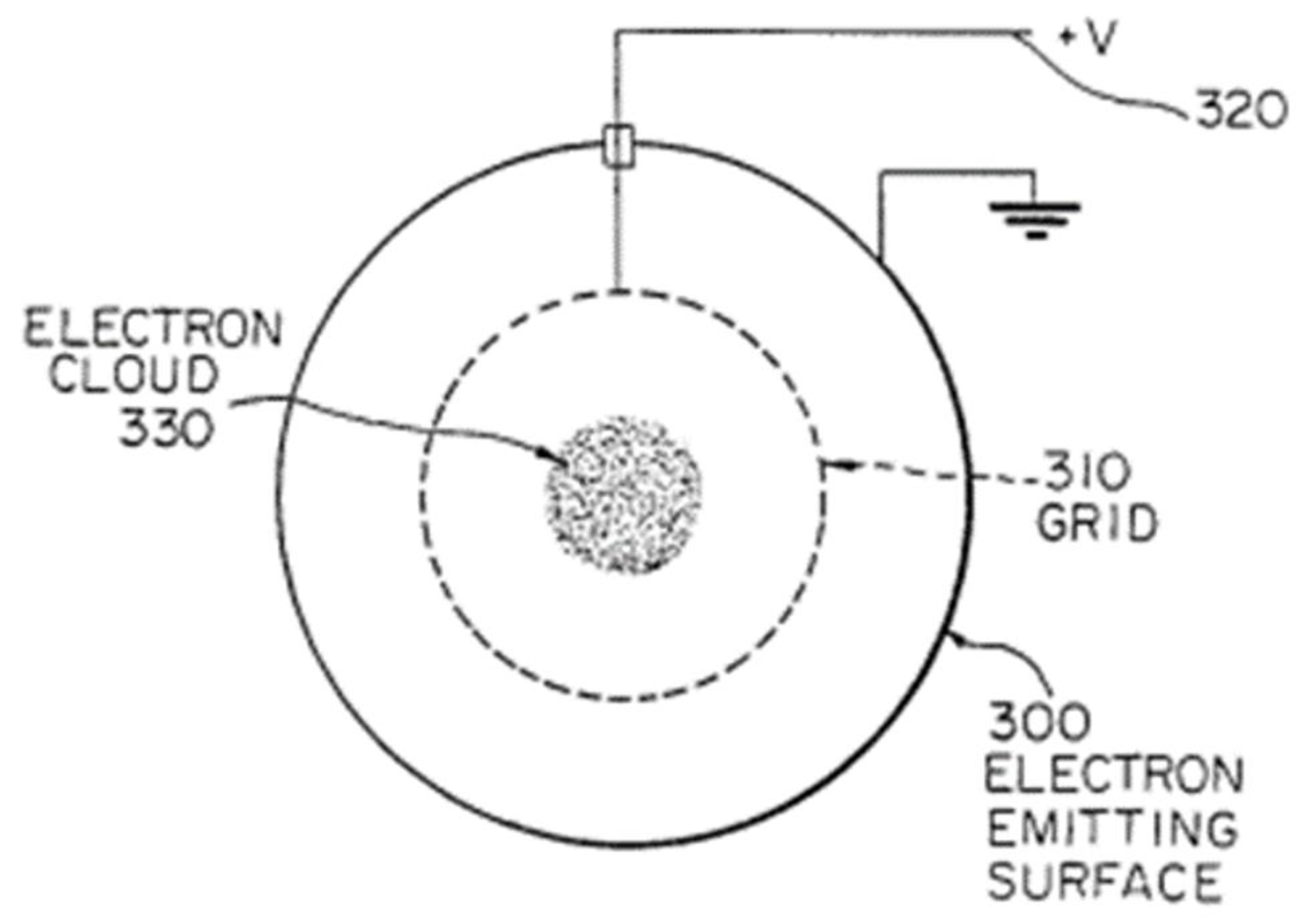
Figure 2.
(left) depiction of Dr. Robert W. Bussard’s method of fusion that shows the current flow used in his patented polyhedron configuration for magnetic confinement; (right) picture of Bussard’s polywell prototype, WB-6.
Figure 2.
(left) depiction of Dr. Robert W. Bussard’s method of fusion that shows the current flow used in his patented polyhedron configuration for magnetic confinement; (right) picture of Bussard’s polywell prototype, WB-6.
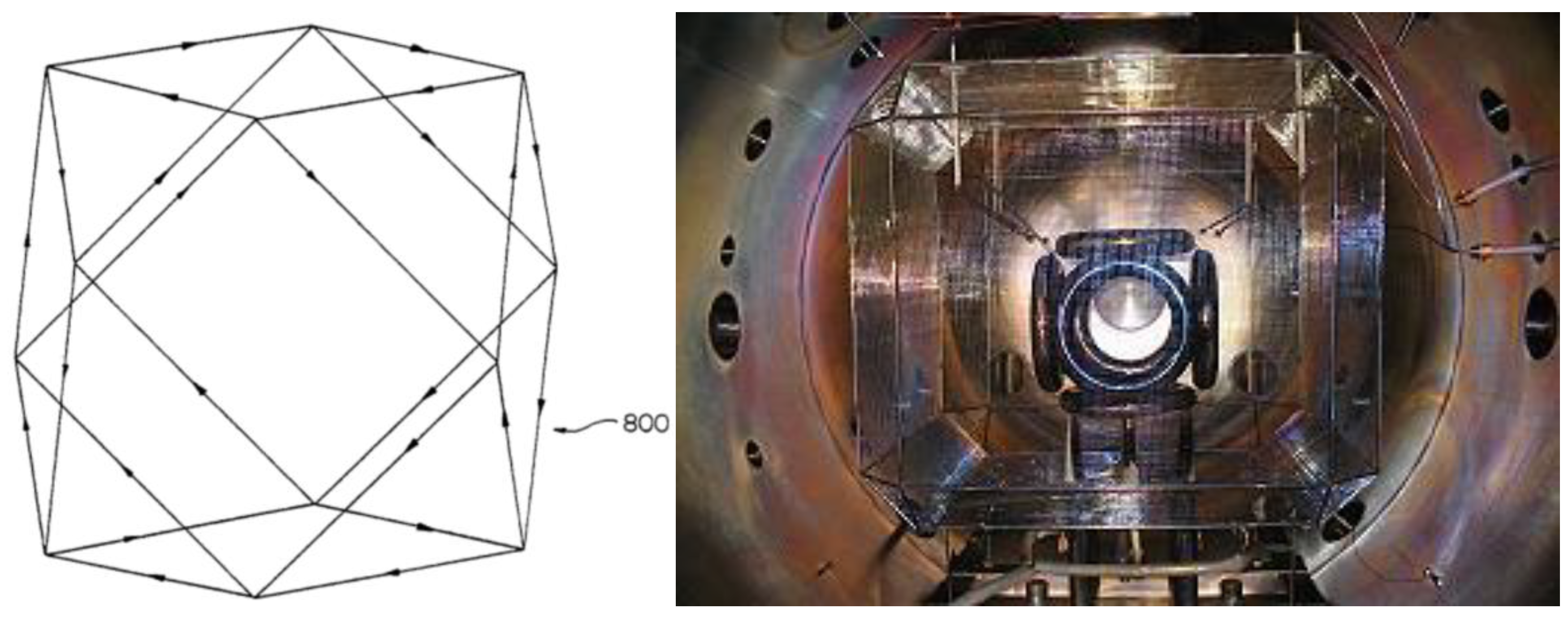
Figure 3.
(left) shows numerically computed electron trajectories for the six coil cusp magnetic configuration from Dr. Park’s patent application; (right) cross-section side view the of polyhedral coil mirroring what is depicted in the left image to present where electron loss occurs.
Figure 3.
(left) shows numerically computed electron trajectories for the six coil cusp magnetic configuration from Dr. Park’s patent application; (right) cross-section side view the of polyhedral coil mirroring what is depicted in the left image to present where electron loss occurs.
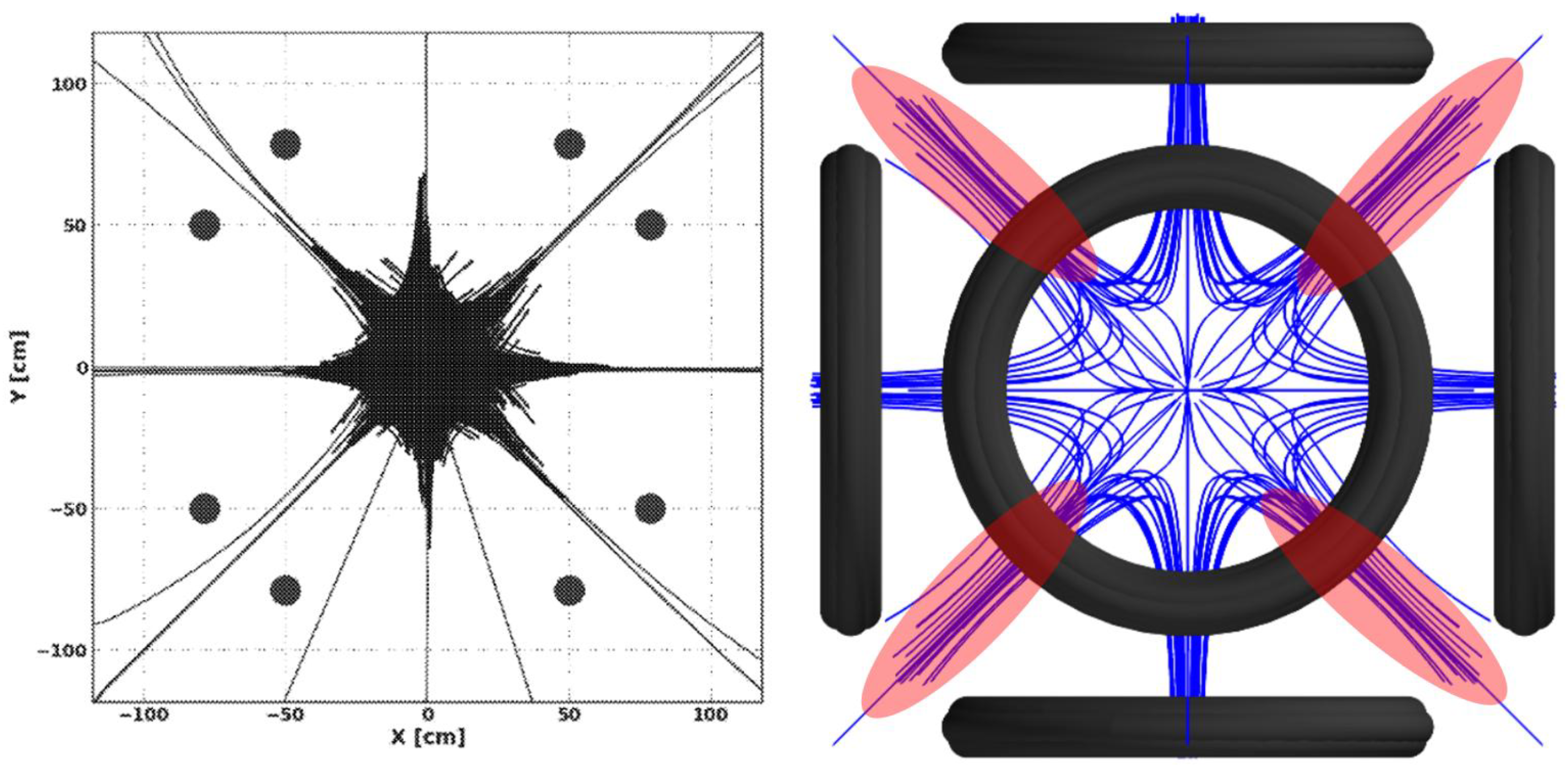
Figure 4.
depiction of how an electron, red arrow trajectory, escapes from the polywell’s magnetic cusps.
Figure 4.
depiction of how an electron, red arrow trajectory, escapes from the polywell’s magnetic cusps.
Figure 5.
(left) image from Dr. Rogers patent presenting prior art from a computer simulation of polywell density distribution for electrons; (right) image from Dr. Rogers patent presenting prior art from a computer simulation of polywell density distribution for ions.
Figure 5.
(left) image from Dr. Rogers patent presenting prior art from a computer simulation of polywell density distribution for electrons; (right) image from Dr. Rogers patent presenting prior art from a computer simulation of polywell density distribution for ions.
Figure 6.
(left) Pentafoil arrangement, which comprises five larger coils surrounding a smaller coil; (right) The more spherical shape of the confinement apparatus due to the pentafoil design.
Figure 6.
(left) Pentafoil arrangement, which comprises five larger coils surrounding a smaller coil; (right) The more spherical shape of the confinement apparatus due to the pentafoil design.
Figure 7.
(left) Cross-section top view showing confinement coils angled to promote a rotation to the confined plasma; (right) Cross-section top view showing the angled magnetic fields overlapping to shield cusps from electron escape.
Figure 7.
(left) Cross-section top view showing confinement coils angled to promote a rotation to the confined plasma; (right) Cross-section top view showing the angled magnetic fields overlapping to shield cusps from electron escape.
Figure 8.
depiction of how an electron, red arrow trajectory, is redirected within the confines of the NESAR’s magnetic fields.
Figure 8.
depiction of how an electron, red arrow trajectory, is redirected within the confines of the NESAR’s magnetic fields.
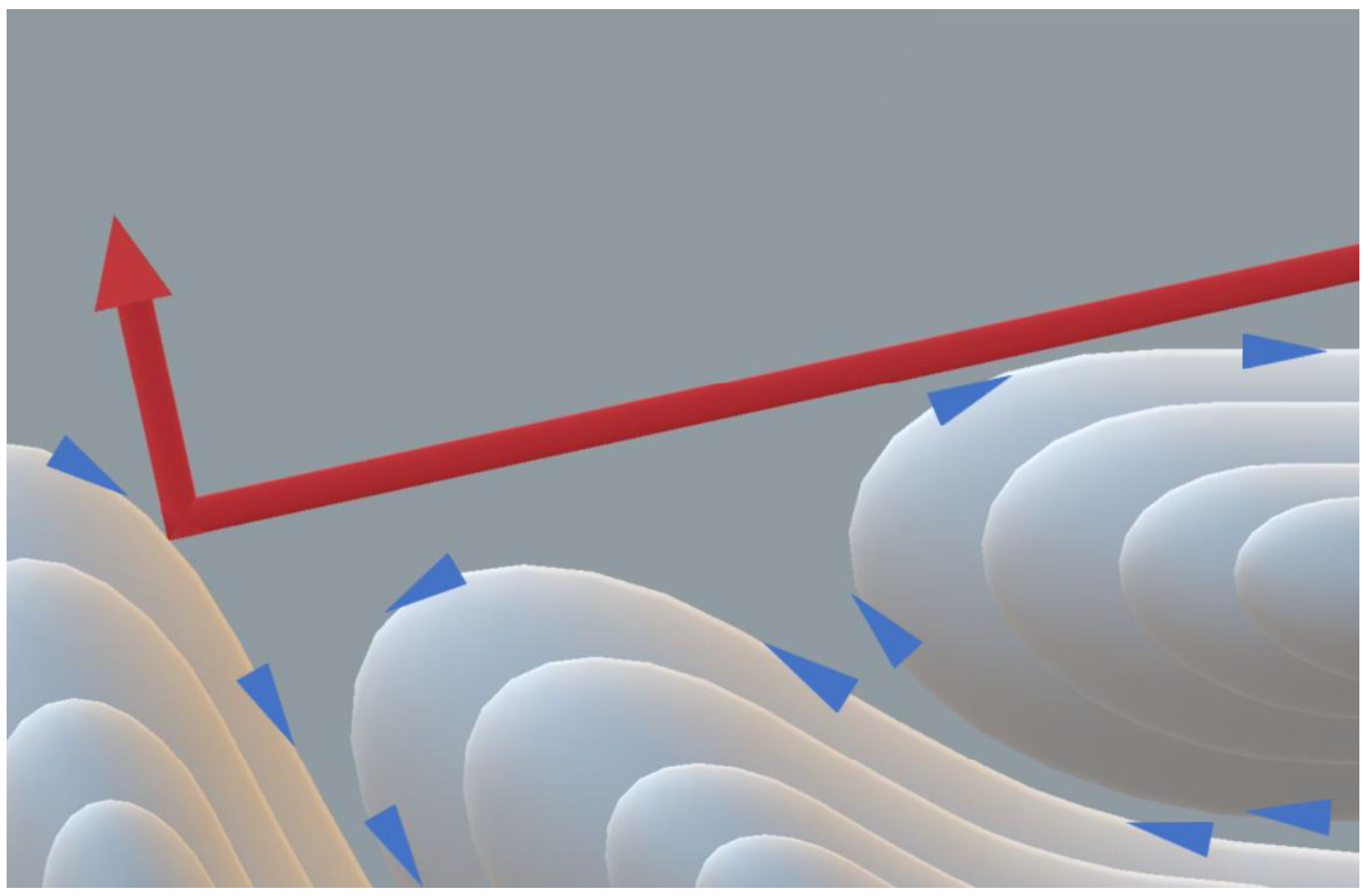
Figure 9.
(left) cross-section top view showing the layering of magnetic cusps and rotation of the confined charged particles generating a magnetic field that increases as more charged particles become restricted within the NESAR; (right) cross-section top view showing how the efficiency of confining charged particles within the NESAR increases as the increasing magnetic field generated by the confined charged particles forces the magnetic cusps to reduce in size and possibly close.
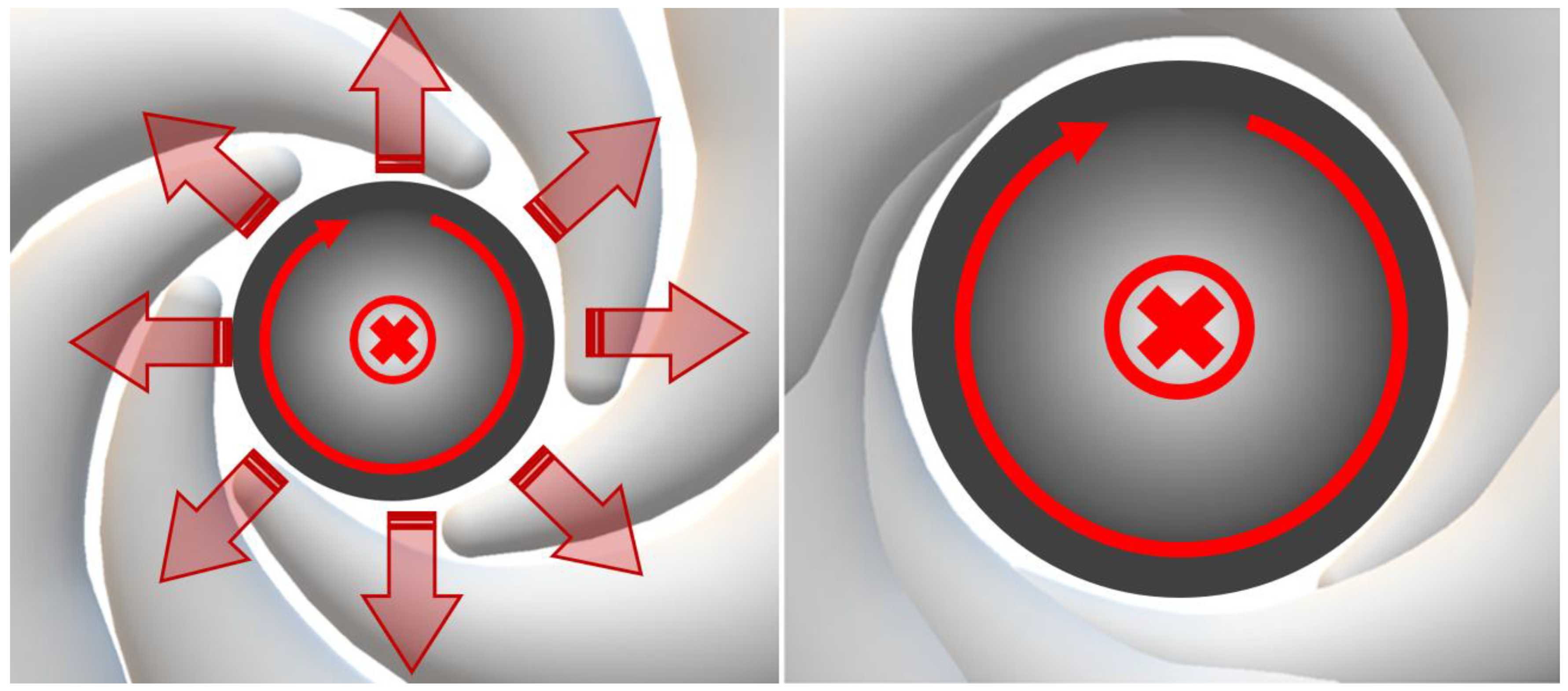
Figure 10.
(left) cross-section top view depicting how a confinement of confined electrons electrostatically interact at the SRCP to generate a Maximized Negative Well Singularity.
Figure 10.
(left) cross-section top view depicting how a confinement of confined electrons electrostatically interact at the SRCP to generate a Maximized Negative Well Singularity.
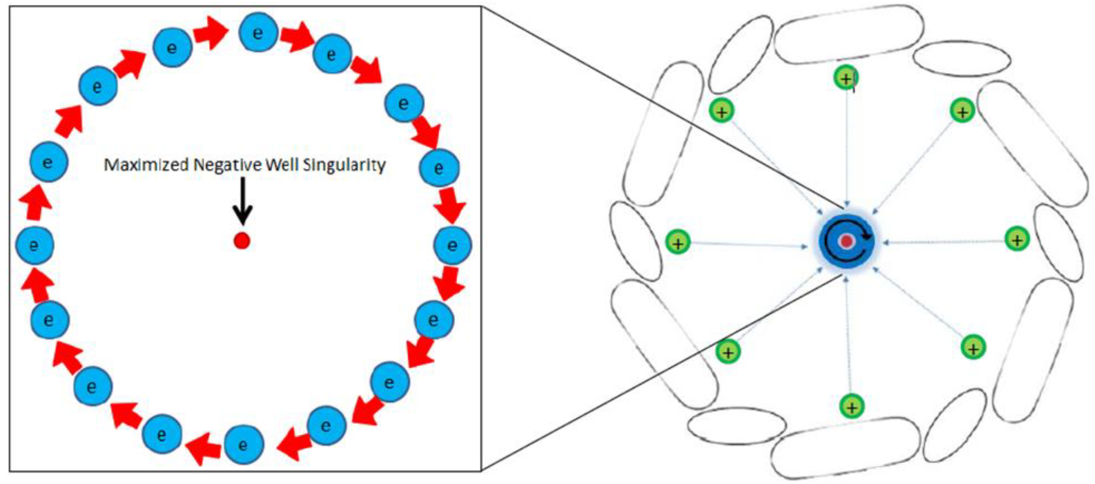
Figure 11.
(left) cross-section side view showing the three different vacuum chambers that the NESAR obtains to emphasize how the confinement apparatus is energized and how the rotors within the ancillary vacuum chambers are rotated by stators that surround the ancillary vacuum chambers; (right) cross-section top view showing the confinement apparatus rotating opposite to that of the rotation of confined charged particles within the confinement apparatus.
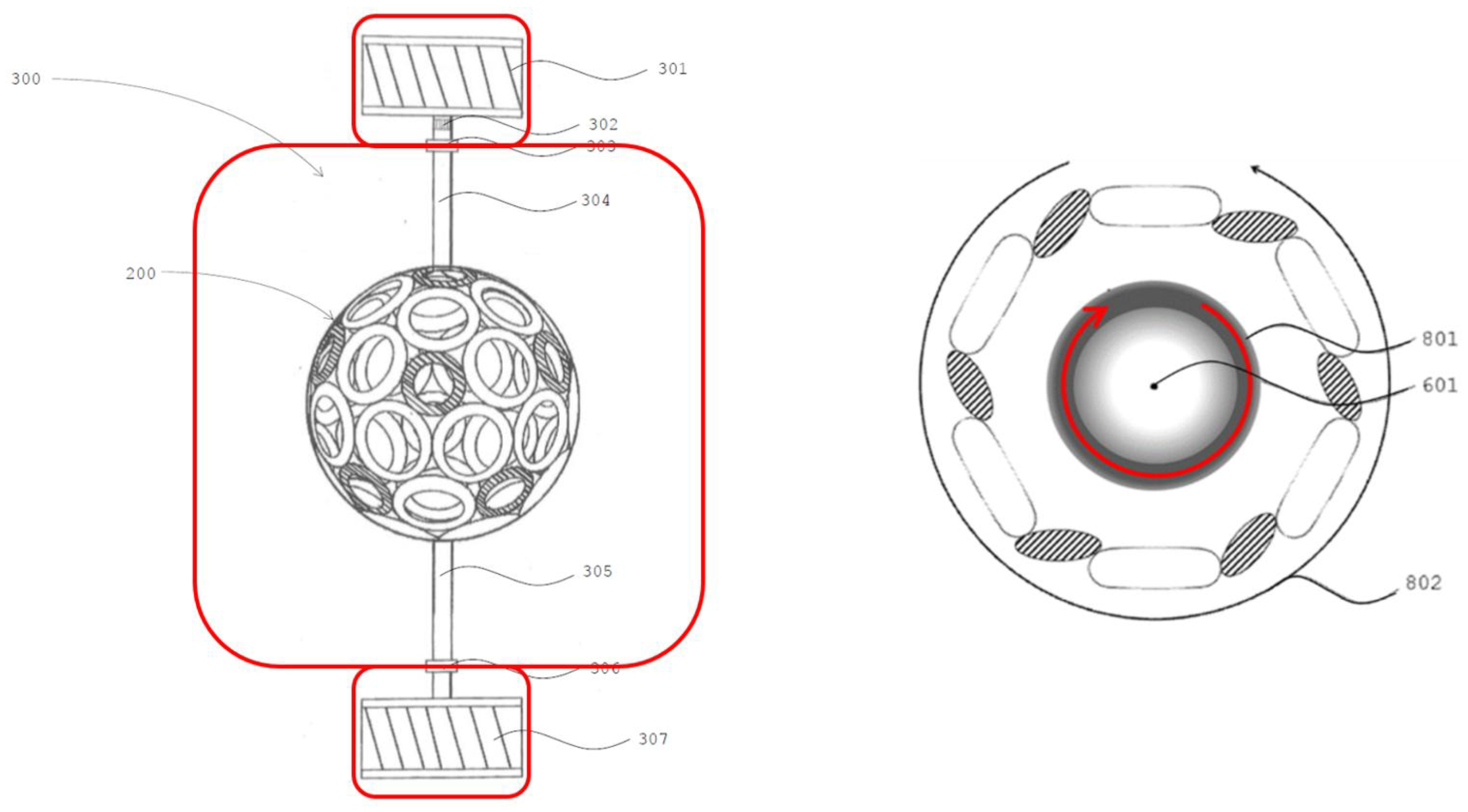
Figure 12.
This view is a cross-section through four magnetic domains undergoing separator Parker-Sweet reconnection. Two separatrices (see text) divide space into four magnetic domains with a separator at the center of the figure. Field lines (and associated plasma) flow inward from above and below the separator, reconnect, and spring outward along the current sheet.
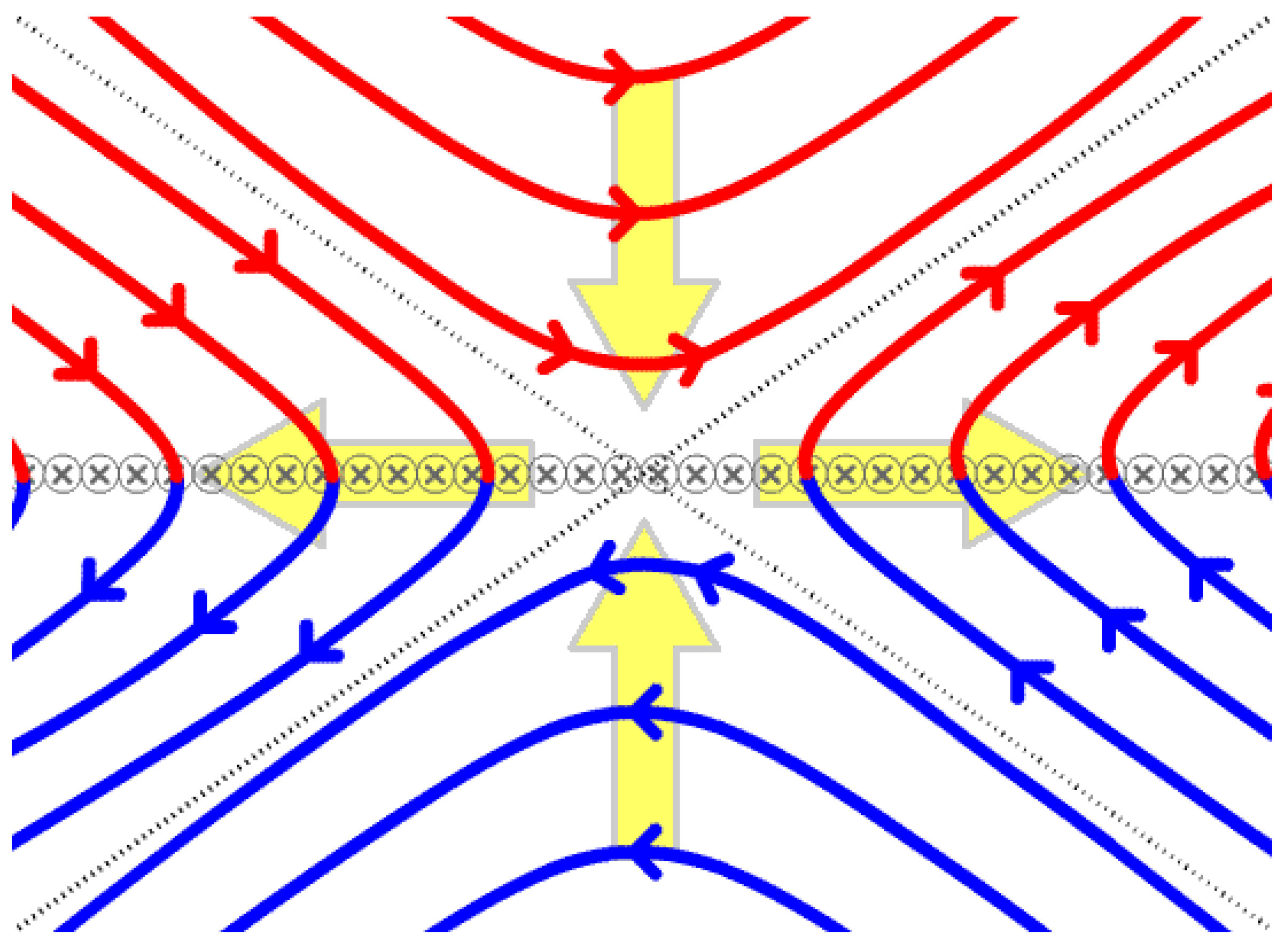
Figure 13.
The progression of a sawtooth magnetic reconnection failure in a tokamak fusion reactor.
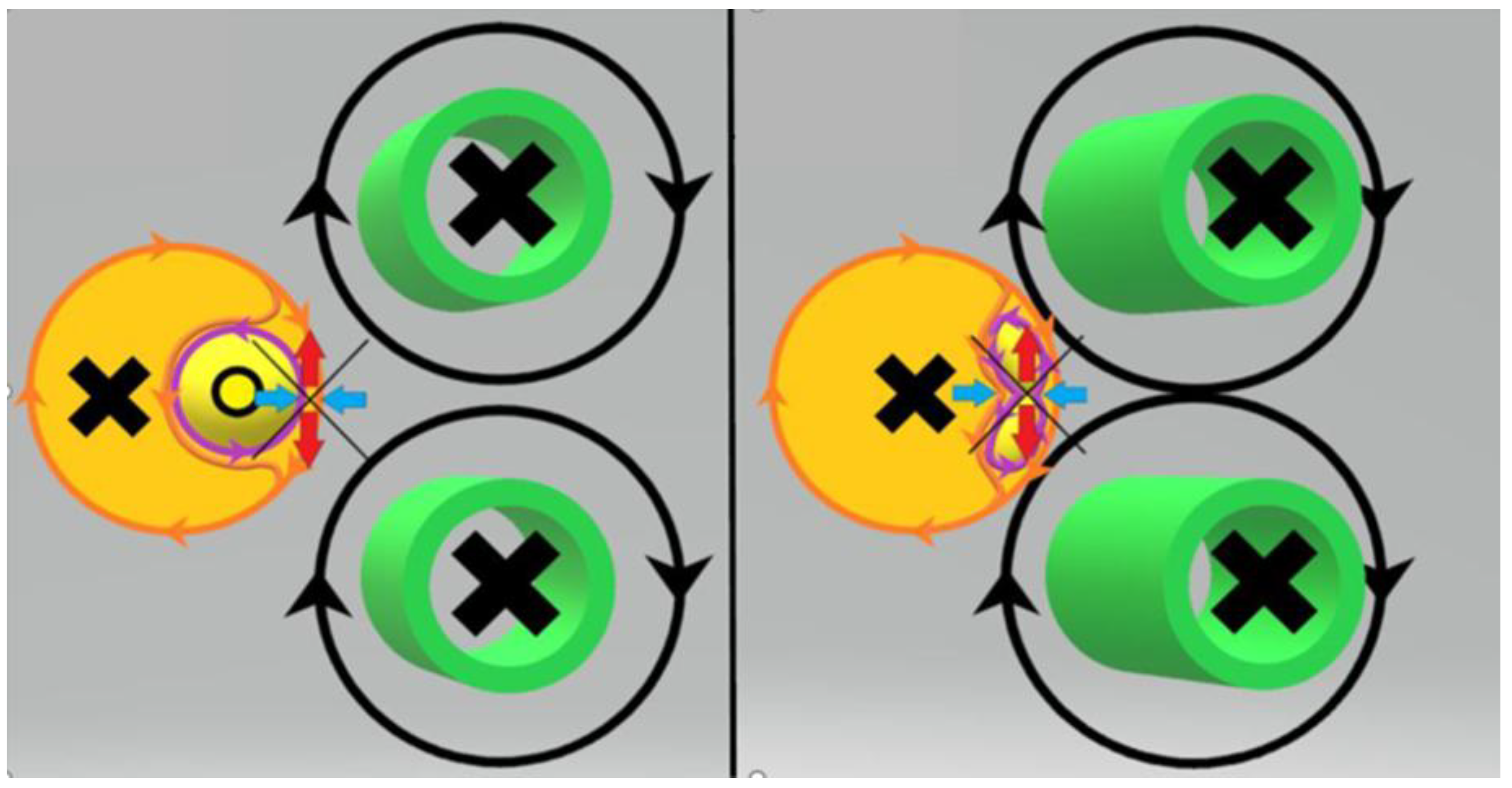
Figure 14.
(left) depiction of a magnetic field within three paralleling currents; (middle) depiction of the three paralleling currents increasing in strength that result in the currents increasing in magnetic strength that add more pressure upon the magnetic field within the currents; (right) depiction of the three paralleling currents creating enough pressure to cause the magnetic field within them to compress upon itself and magnetically reconnect.
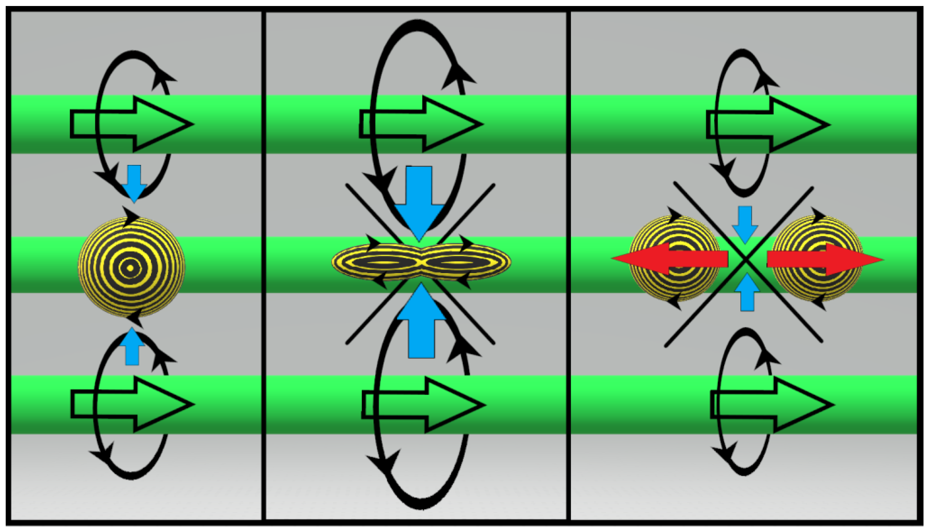
Figure 16.
depiction of the tokamak’s correction coils, in green, and ELMs, in blue.
Disclaimer/Publisher’s Note: The statements, opinions and data contained in all publications are solely those of the individual author(s) and contributor(s) and not of MDPI and/or the editor(s). MDPI and/or the editor(s) disclaim responsibility for any injury to people or property resulting from any ideas, methods, instructions or products referred to in the content. |
© 2025 by the authors. Licensee MDPI, Basel, Switzerland. This article is an open access article distributed under the terms and conditions of the Creative Commons Attribution (CC BY) license (http://creativecommons.org/licenses/by/4.0/).
Copyright: This open access article is published under a Creative Commons CC BY 4.0 license, which permit the free download, distribution, and reuse, provided that the author and preprint are cited in any reuse.


