
Submitted:
06 January 2025
Posted:
07 January 2025
You are already at the latest version
Abstract
Environmental issues have garnered significant attention from younger generations. Students recognize the importance of envisioning sustainable development for countries that have not yet reached full industrialization. Additionally, students are aware that productive processes in industrialized nations must undergo a transition to methods based on renewable energies. In this work, we elucidate the concept of sunlight trapping and suggest some educational applications. Furthermore, to encourage students' creativity and exploration, we briefly discuss feasible applications of the concept of sunlight trapping.
Keywords:
renewable energies
; physics education
; sunlight trapping
1. Introduction
Young people are expressing serious concerns about the Earth’s climate balance, loudly calling for a transition from a production model based on fossil fuels to one based on renewable energies. Among all alternative energy sources to oil, solar energy is the most immediately available in areas with good insolation. It is estimated that it may be technically possible to derive 60 TW of power from solar radiation in the near future [1]. This figure, when compared to the global demand, which was 12.5 TW in 2009 and is projected to be approximately 16.9 TW by year 2030 [1], gives us an idea of how crucial it is to consider, on rigorous scientific bases, certain aspects related to the conversion of solar energy into electricity.
For example, the question of whether it is possible to capture sunlight incident on a given surface deserves attention from the scientific community due to the possible technical-practical implications in the field of renewable energy production. In fact, as early as 2004, in an interview with La Repubblica [2], Carlo Rubbia explained the importance of optical systems that intercept and capture sunlight to produce electricity. In the experimental plant of Priolo Gargallo [3], in Sicily, conceived by Rubbia himself during his tenure at ENEA, parabolic profile mirrors are capable of concentrating sunlight onto a linear array of focal points where molten salts flow, heated to a temperature of about 550°C, and used to produce high-temperature and pressure steam. The steam is sent to a nearby combined cycle plant. In this way, the energy obtained from the concentration of solar rays could contribute to the production of electricity.
In this paper, a method for capturing sunlight using mirrors with various profiles is presented, along with potential applications. If tested, the proposed systems could offer valuable insights into their practical viability for energy conversion purposes. The analysis is specifically designed to cater to high school students. Therefore, in the following section the focal properties of the parabola and the ellipse are recalled for the use of high school students. In the third section, two optical systems, the first consisting of the combination of one parabolic and one elliptical mirror, and the second consisting of two parabolic mirrors, are proposed as possible primary elements that allow the capture of sunlight. Further applications, using geometric optics, are illustrated to stimulate students in conceiving new optical systems for solar energy harvesting. Final considerations are reported in the last section.
2. Focal Properties of the Parabola and of the Ellipse
The term “focus” in optics is used to define the point where a beam of light, coming from infinity, converges after reflection. It is well known that the concept of focus in spherical mirrors can be used if the light rays of the beam, directed along the optical axis, are sufficiently close to the latter (paraxial rays) [4]. In fact, spherical aberration pertains to the geometric impossibility of finding such a unique point for a spherical mirror.
A useful exercise in analytic geometry could therefore be the following. Consider a concave spherical mirror and an incident light ray parallel to the optical axis coming from infinity. Prove that the intersection between the optical axis and the reflected ray depends on the point of incidence.
For a parabola, we do not need to require that the rays be paraxial, because all rays parallel to the optical axis coming from infinity that strike a parabolic mirror are reflected, regardless of the point of incidence, to a single point known as the focus.
2.1. Focal Properties of a Parabolic Mirror
Since we use parabolic-profile antennas on our roofs, a second useful exercise in analytic geometry could be to prove that the line resulting from the reflection of a vertical line (see Figure 1) by a parabola with the expression always passes through the focus , regardless of the point of incidence. In this case, we provide a brief hint at the solution to the problem.
Referring to Figure 1, considering that the slope of the normal line to the curve at is equal to , and that the angle of incidence is equal to the angle of reflection, we can observe that . The line describing the direction of the reflected ray is inclined at an angle with respect to the horizontal. Therefore, the equation of the reflected ray will be as follows:
where is the ordinate of the point of incidence on the parabola, and represents the slope of the reflected ray. This equation describes the path of the reflected ray, which, as mentioned earlier, will pass through the focus of the parabola. The intercept of this line with the -axis is obtained by setting , so we have:
Since , we have:
Substituting Equation (3) into Equation (2), we obtain:
Therefore, regardless of , rays coming from infinity and parallel to the optical axis of a parabolic mirror are reflected such that they pass through the focus of the parabola.
2.2. Focal Properties of an Elliptical Mirror
We can observe that the ellipse has focal properties such that if an incident ray originates from one of the two foci, the reflected ray passes through the second focus, as shown in Figure 2. This can be proven by applying Heron’s theorem, which states that if and are two points outside a line , the point P on the line that minimizes the sum of the distances and is the point where the segments and form equal angles with the line . Being a point on the ellipse, the minimum sum is equal to the length of the major axis.
This theorem can be used in non-advanced optics courses to prove that the angle of reflection is equal to the angle of incidence. In fact, light propagates through a single medium both before and after reflection, so the path that minimizes distance also minimizes time, which, according to Fermat’s principle, is the path that a light ray follows, whether it is reflected from a smooth surface or refracted in a transparent medium.
3. Combined Optical Systems
The two focal properties analyzed in the previous section, although they might seem trivial at first glance, constitute the essential concepts in solar light capture. In fact, by coupling two mirrors—one with a parabolic profile and the other with an elliptical profile—that share the same focus, as shown in Figure 3, we can observe the following.
Referring to Figure 3, let us align the focus of a parabolic mirror P with the first focus of an elliptical mirror E. Then, place the vertex of P at the second focus of E. We can see that a light ray coming from infinity, parallel to the optical axis of the mirror system described, will be incident on P at point , be reflected through point , and, after the second reflection, pass through the vertex of the parabolic mirror P.
Now, imagine making a small hole at so that all the rays coming from infinity, parallel to the optical axis and incident on the parabola, can be directed to the same vertex . At this point, a very high concentration of sunlight will be realized in the proximity of the vertex . The aperture of the primary mirror must be carefully matched with that of the secondary mirror. This study has been conducted in ref. [5]. From these focal properties, several applications for energy production can arise, which we will briefly outline in the following paragraphs.
Before moving on to the practical side, let us calculate the light intensity that reaches the Earth from the Sun before it is attenuated in the atmosphere. This calculation can be presented to high school students as a useful exercise in discussing Stefan-Boltzmann’s law [6]. Let’s start by considering that our Sun is a star with an average radius of and a surface temperature of about . It is located at an average distance of from the Earth. Using Stefan-Boltzmann’s law, we can calculate the radiant power of our star as follows:
where . The power will be intercepted by the Earth at the distance , and the light intensity at the upper layers of our atmosphere can be calculated as follows:
Substituting the values specified above, we obtain . Considering the portion of light reflected and absorbed by the atmosphere, we can approximate the light intensity at the Earth’s surface, on a clear day, to about . This calculation could be useful in confirming estimates made by researchers Jacobson and Delucchi [1], for example. Alternatively, by considering an approximate power demand of by year 2030 [1], one can calculate the square surface with a fairly good solar exposure of necessary to obtain the power . By the setting one has . The surface is thus about and corresponds to of the surface of the Sahara Desert, which has an extension of about . These calculations can raise students’ awareness of the real possibility of using a renewable source to meet the energy needs of all mankind.
4. Didactical Applications
To stimulate student’s ability to imagine innovative ways of harvesting and storing solar energy, we might give some practical examples. In fact, this teaching proposal can be used as an introducing topic in a lecture following an Inquiry Based Science Education (IBSE) approach [7]. In fact, a simple demonstration, involving only common material can be given in the classroom. For example, the properties of parabolical mirrors can be shown to students with strips of acrylic mirrors shaped in the form of a parabola. This classroom demonstration can serve as an “engage” phase in the IBSE approach. This phase could immediately precede the “explore” phase, where more situations can be experimented and discussed. An “explain” phase might follow, where students are asked to delve in to the focal properties of curved mirrors. Finally, the work can be extended to other system, as it will be suggested in the present work.
First imagine we were to place an access point for light at the vertex of the parabola P in Figure 3, corresponding to an absorbing body. By doing this, we could store the energy coming from the Sun. In this sense, we can say that we are able to capture solar light, except for the losses due to reflection on the surfaces of the mirrors [8].
A schematic representation of the path of two light rays in the case where the secondary mirror has an elliptical profile is shown in Figure 4a. In this figure, it is evident how, through the hole made at the vertex of the parabola, which coincides with the second focus of the secondary mirror, light can be directed into the part of the paraboloid opposite to the illuminated one. In Figure 4b, the path of two light rays is depicted for the case where the secondary mirror has a parabolic profile. In both scenarios, the system of the two mirrors, rigidly connected to each other, must track the Sun in its apparent motion across the sky so that the rays arrive parallel to the optical axis of the mirror system shown in Figs. 4a and 4b. Therefore, it is necessary to equip the optical system with a solar tracker that aligns the optical axis toward the Sun. Alternatively, it is possible to use profiles of the primary mirror designed to reduce the sensitivity to misalignment between the system and the rays coming from infinity [9].
If the collecting parabolic reflector that gathers solar rays has an aperture radius of 1 meter, we could obtain approximately 3 kW of electromagnetic power. In fact, as previously mentioned, we can intercept about 1 kW of electromagnetic power for every square meter of surface exposed to the Sun on a clear day.
An experiment conducted in Sala Consilina (Italy) by the students of Liceo Classico “M. T. Cicerone” is shown in Figure 5: Following the scheme in Figure 4a, rays from two laser pointers on the left side are concentrated in the vertex of a parabolic mirror. If a perfectly absorbing body (black body) is placed at this point, we can effectively “capture” sunlight. This experiment demonstrates how a parabolic mirror can focus light rays in a single point, significantly increasing the intensity of the light and making it possible to capture and utilize solar energy efficiently.
A black body can be realized by means of a cavity with a small opening and with perfectly reflecting inner walls. In the case of a circular cavity, for example, we can envision multiple reflections inside the cavity by means of simple geometric constructions.
In Figure 6, the trajectories of two light rays inside a circular cavity of radius are represented. The light rays, one in red and the second in orange, enter the cavity through a small opening in , the first at an angle , the second at an angle with respect to the -axis. The first ray is reflected in , where one notices that the incident and reflected angles are equal to . The second ray is reflected in , following a similar pattern. After reflection in , the ray is reflected in . Again, the incident and reflected angles in are equal to . A similar pattern is followed by the second light ray. The number of reflections can be rather high, before the ray escapes from the circular cavity. The escape time depends both on and on the relative size of the opening [10]. The sequences of incidence points , , , … and , , , … can thus be represented by means of the graphical construction given in Figure 6. Because of the law of reflection, in fact, the inner concentric circle, of radius , plays the role of a forbidden area for the light ray, so that all points of the trajectories lie outside the open circle of radius . Furthermore, all rays must be tangent to this inner concentric circle because all triangles and () must be isosceles.
Therefore, in the case of the configuration in Figure 4a, we can concentrate sunlight into a very small region of space and subsequently trap it in an absorbing body. This absorbing body can have a small opening that coincides precisely with the hole made at the vertex of the paraboloid of revolution (primary mirror). The absorbing body could contain, for instance, water in an internal chamber for steam production as shown in Figure 7.
In the schematic cross-sectional view of this additional part in Figure 7, the entire system is enclosed in an insulating jacket, and the plate P, which is in contact with a water container A, is made of absorbent material. Moreover, the internal walls R of the cavity depicted in Figure 7 are reflective so that light reflected from the plate P can be redirected onto it after reflecting off the internal walls of the cavity. Depending on the size and number of paraboloids juxtaposed with the structure in Figure 7, which can extend horizontally, the system can produce sanitary water or steam. The same structure, if rigidly connected to the optical system, must not only be able to rotate around the vertical axis but also around horizontal axis . The former rotation is achieved by mounting the entire apparatus on a rotating platform. A possible diagram of the final apparatus could be the one shown in Figure 8.
The systems depicted in Figure 8 could also be used as desalination units (or as purifiers of contaminated water), if one recovers the vapor from the top of the cavity and removes the salt (or pollutant residues) from the bottom. Finally, it should be noted that the structure described in Figure 8 could be mounted vertically to save space. However, in this case, additional measures would need to be taken in the design. For example, if we wanted a cylinder with a fixed (non-rotating) support, we would need to allow the paraboloids to rotate, detaching them from the rigid connection with the cylindrical cavity. This can be achieved by using high-temperature optical fibers as connectors between the vertex of the primary paraboloid and the entrance to the cylindrical cavity, as shown for a different application in Figure 9.
Among the possible applications of the systems schematically represented in Figure 4b, we can mention the use of these optical systems in the field of concentrated photovoltaic (PV) cells [11]. As for traditional photovoltaic cells, the optical system in Figure 4b could be used, as shown in Figure 9, to illuminate modules of photovoltaic devices enclosed within chambers with reflective inner walls. The purpose of these chambers would be to protect the modules from dust and the elements and to filter out frequencies that are not absorbed by the photovoltaic cells, thus preventing excessive heating, which leads to a decrease in the efficiency of the conversion process from radiant energy to electrical energy [12]. In fact, we might recall that only visible and near infrared bands contribute to creation of hole-electron pairs in a photovoltaic cell, while other frequencies, as those in the far infrared band, only contribute to transfer thermal energy to this device.
4. Discussion
In this work, we explored potential applications of solar light capture, achieved through the concentration of sunlight using mirrors with various profiles. We observed that an efficient way to store solar energy is by coupling these optical systems with an absorbing body. Additionally, we sought to address two questions that might arise from young students interested in the topic of alternative energies, drawing upon existing scientific literature.
The first question is how energy from the Sun can be practically stored using these optical systems. Our answer, as mentioned above, involves combining parabolic and elliptical mirrors. However, it’s important to clarify that this is not the only possible solution. For instance, one could also design refractive systems like the one proposed by De Luca et al. [13]. These optical systems have a unique characteristic: while they concentrate the light beam, they do not alter the direction of the rays, making them particularly efficient for driving concentrated photovoltaic (CPV) cells [11]. These systems will be the subject of future research.
The second question that might arise is whether the energy delivered by the Sun to Earth is sufficient to meet the current needs of all humanity. Thanks to the work of Jacobson and Delucchi [1], we can confidently answer this question affirmatively.
In conducting this work, we considered two key factors. The first is that young people not only need answers to their legitimate questions but also need new ideas to tackle the challenges of the new millennium in the field of energy. These ideas must be tested before they might find place in the productive world. The second factor pertains to educational aspects: the optical systems we have discussed possess properties that can be derived through concepts of analytic geometry, which are accessible to high school students. This serves as evidence that the knowledge gained in school can lay the foundation for a sustainable future, where our young students will undoubtedly be the architects.
Funding
This research received no external funding.
Data Availability Statement
The original contributions presented in the study are included in the article/supplementary material, further inquiries can be directed to the corresponding author.
Conflicts of Interest
The authors declare no conflicts of interest.
References
- Jacobson, M.A.; Delucchi, M.Z. A path to sustainable energy to 2030. Scientific American 2009, 301, 58-65. [CrossRef]
- La Repubblica. Available online: https://ricerca.repubblica.it/repubblica/archivio/repubblica/2004/05/19/rubbia-la-centrale-di-archimede-cosi-catturero.html (accessed on 26 August 2024).
- Enel. Available online: https://www.enel.com/content/dam/enel-com/pressrelease/porting_pressrelease_IT/1501003-1_PDF-1.pdf (accessed on 26 August 2024).
- Sears, F.W.; Zemansky, M.W.; Young, H.D. University Physics, 5th ed.; Addison-Wesley: Reading, MA, 1977; pp. 665–674.
- De Luca, R.; Fedullo, A. Focusing light rays back to the vertex of a reflecting parabolic collector: the equivalent of Dionisius ear effect in optical systems. Eur. J. Phys. 2009, 30, 935–943. [CrossRef]
- Halliday, D., Resnick, R., Walker, J. Foundamentals of Physics, 10th ed.; John Wiley & Sons: Hoboken, NJ, 2013; pp. 534–539.
- Gillies R. M. Inquiry-Based Science Education 1st ed.; CRC Press: Boca Raton, FL, 2020.
- De Luca, R.; Romeo, F., Zozzaro, P. Capturing sunlight. Eur. J. Phys. 2006, 27, 347–352. [CrossRef]
- Parretta, A., Antonini, A., Bonfiglioli, E., Campa, M., Vincenzi, D., Martinelli, G. Il metodo inverso svela le proprietà dei concentratori solari. PV Technology 2009, 30, 58–64.
- De Luca, R. Numerical evaluation of the escape time of a classical point particle from an annular billiard. Rev. Bras. Ens. Fis. 2010, 32, 33061-33064. [CrossRef]
- Conibeer, G. Third-Generation Photovoltaics. Materials Today 2007, 10, 42–50. [CrossRef]
- Nelson, J. The Physics of Solar Cells, 1st ed.; Imperial College Press: London, UK, 2003; pp. 289–324.
- De Luca, R., Faella, O., Zozzaro, P. Light concentration by means of spherical thick lenses. Int. J. Opt. Appl. 2014, 4, 1–5.
Figure 1.
A light ray coming from infinity in a direction parallel to the optical axis of a parabolic mirror reflects at the focus of the parabola.
Figure 1.
A light ray coming from infinity in a direction parallel to the optical axis of a parabolic mirror reflects at the focus of the parabola.
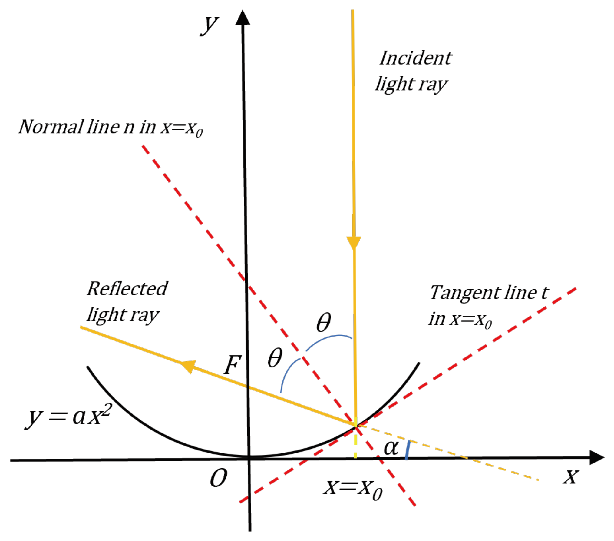
Figure 2.
Considering the segment as an incident ray at point on the ellipse, the segment will represent the reflected ray. Indeed, according to Heron’s theorem, the point on the tangent line that minimizes the sum of the distances and is the point where the segments and form equal angles with the line and, therefore, also with the normal .
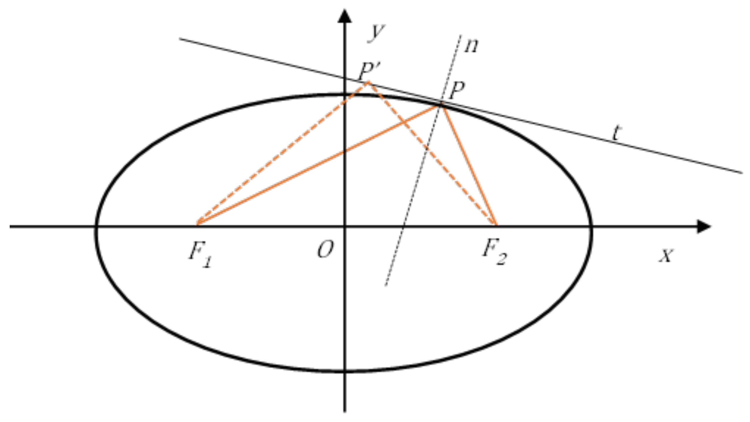
Figure 3.
A primary mirror P with a parabolic profile is combined with a secondary mirror E with an elliptical profile. The two mirrors share a common focus , such that a ray coming from infinity, parallel to the optical axis and incident on P, is reflected at . After a second reflection on the secondary mirror, the ray reaches the vertex of the parabola, where the second focus of the elliptical mirror is located.
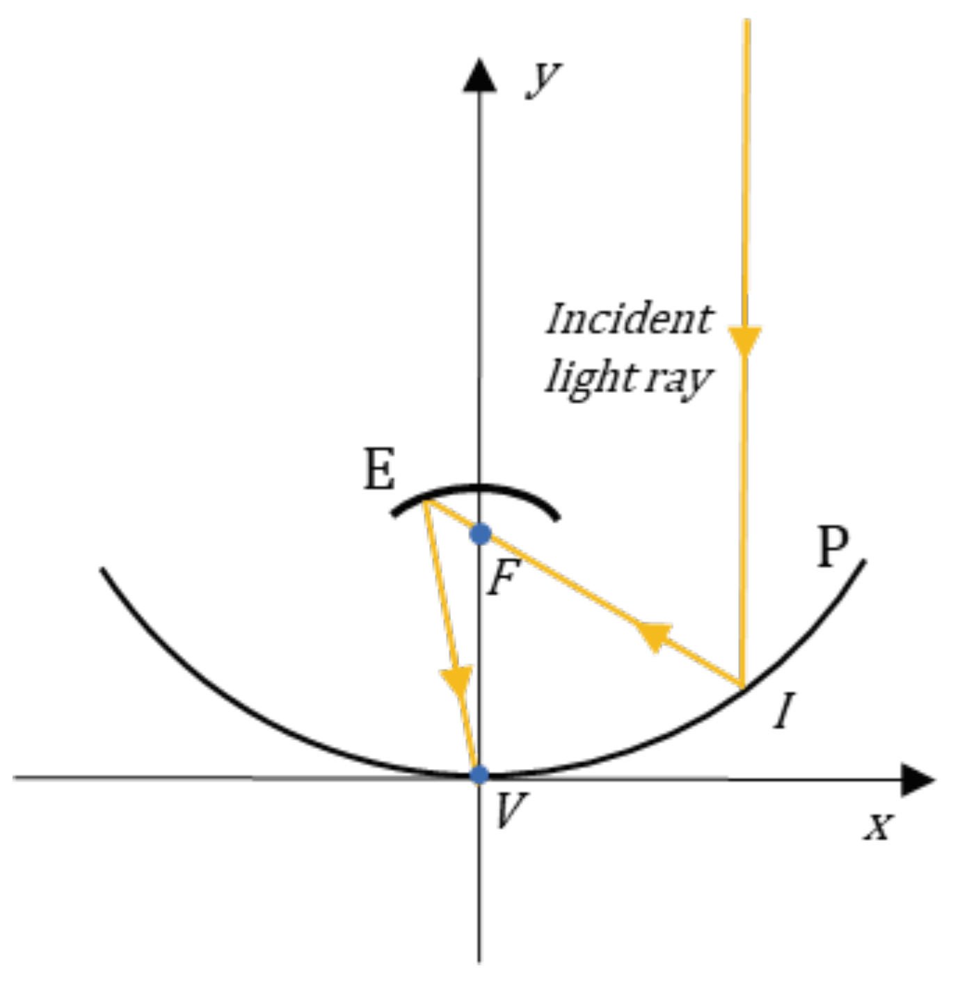
Figure 4.
Schematic representation of the path followed by two light rays, originating from infinity and parallel to the optical axis, incident on a paraboloid of revolution with an aperture radius . These rays are reflected so that they pass through the focus of the paraboloid of revolution. (a) The paraboloid has its focus at , which coincides with the focus of a secondary mirror with an elliptical profile, whose second focus is at ; (b) The paraboloid has its focus at , which coincides with the focus of a secondary mirror that also has a parabolic profile.
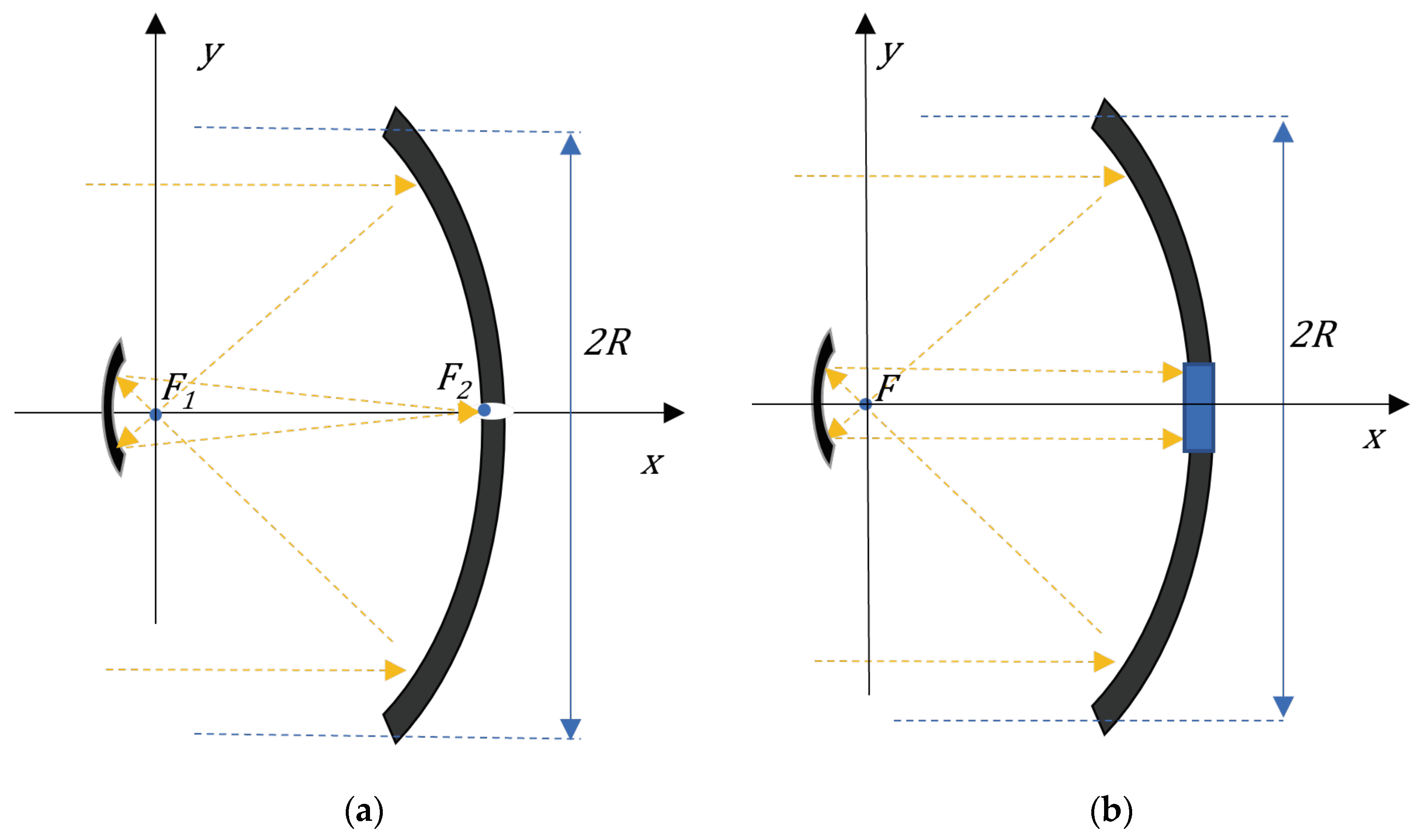
Figure 5.
Experimental realization of the reflection scheme in Figure 4a for didactical purposes. Rays coming from two laser pointers are concentrated in the vertex of a parabolic mirror.
Figure 5.
Experimental realization of the reflection scheme in Figure 4a for didactical purposes. Rays coming from two laser pointers are concentrated in the vertex of a parabolic mirror.
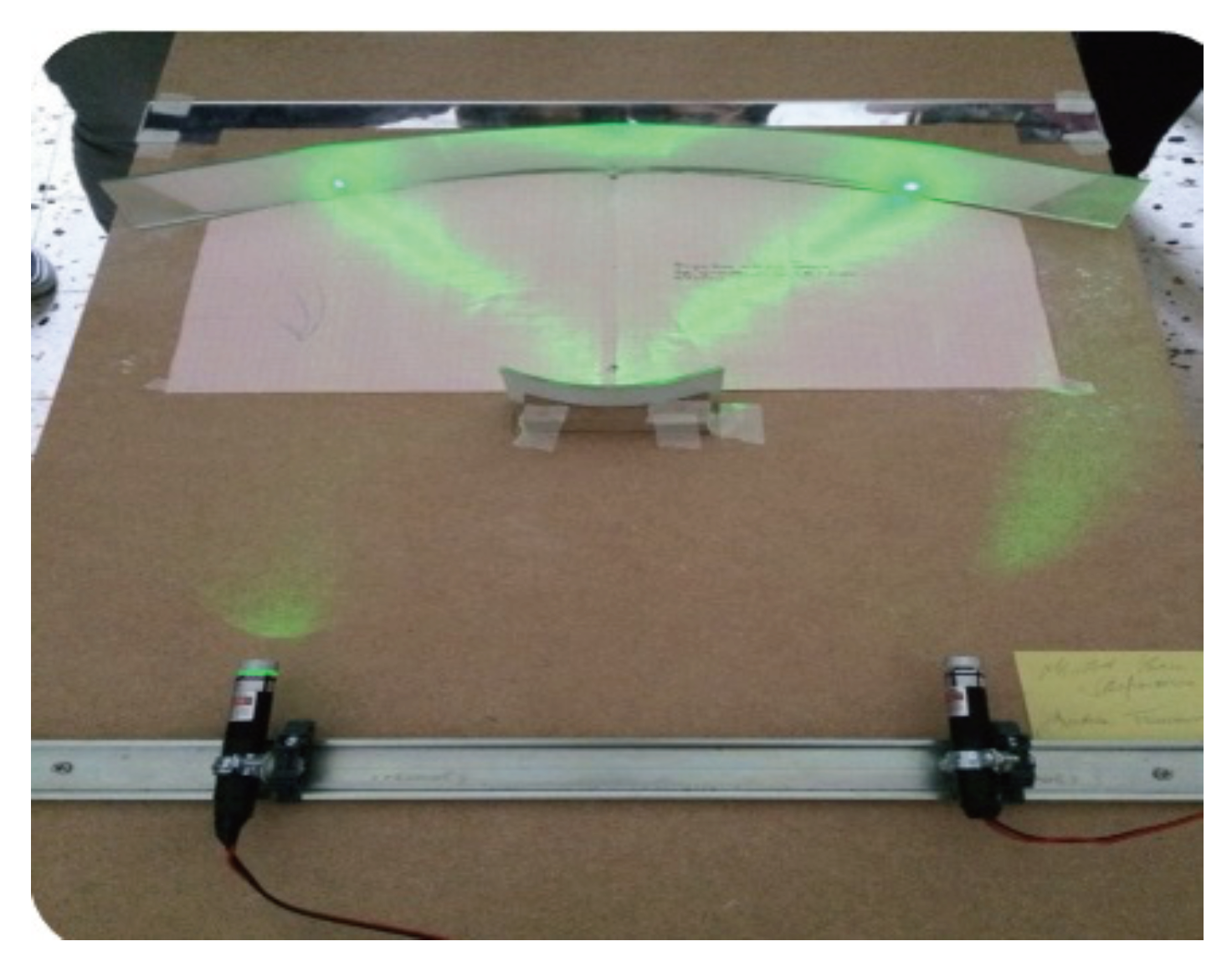
Figure 6.
Trajectories of two light rays inside a circumference of radius and center . All segments making up the piecewise continuous trajectories are tangent to a smaller concentric circumference of radius , where and are the angles that the two light rays (the first drawn in red, the second in orange) make with the -axis.
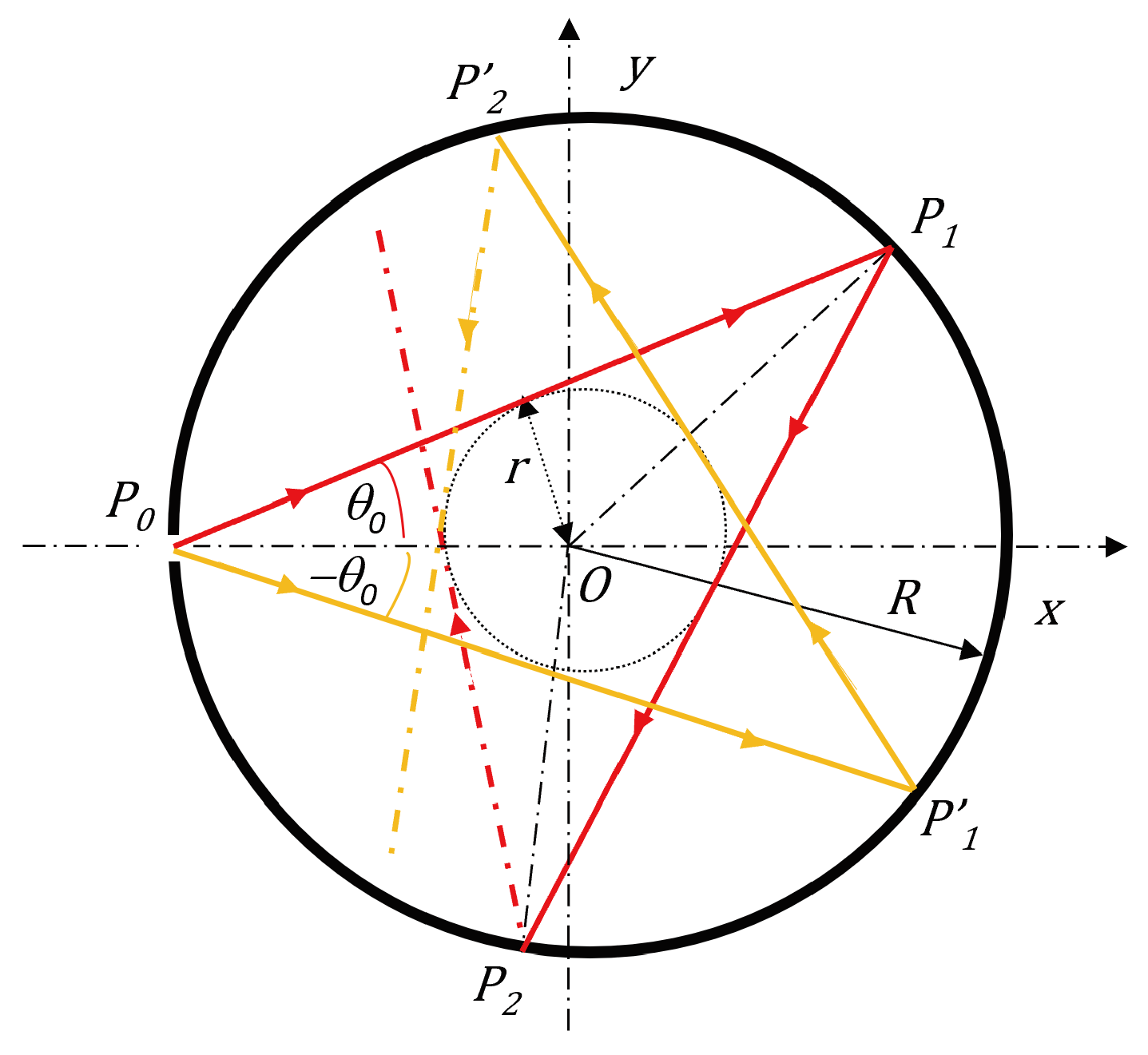
Figure 7.
Schematic structure of the central section in the plane of the absorbing body. The axis is orthogonal to the figure. Concentrated light enters through the hole F, placed at the origin of the plane, diffusing within the chamber with reflecting walls R. The light then strikes an absorbent plate P, which is in contact with a container A holding water.
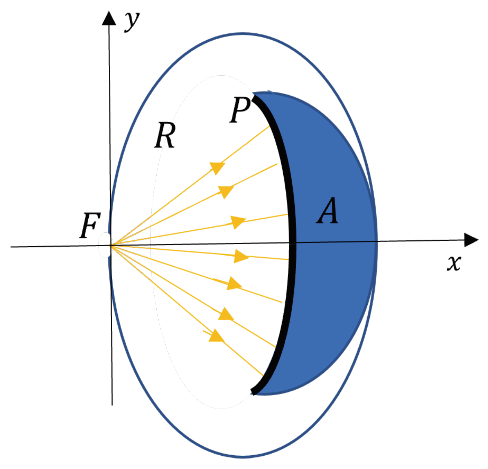
Figure 8.
The optical system in Figure 4a is rigidly connected to the structure shown in section in Figure 7. The final apparatus must be able to rotate around the vertical -axis and the horizontal -axis to allow the optical axes of the paraboloids (all aligned with each other) to be oriented parallel to the light rays coming from the Sun.
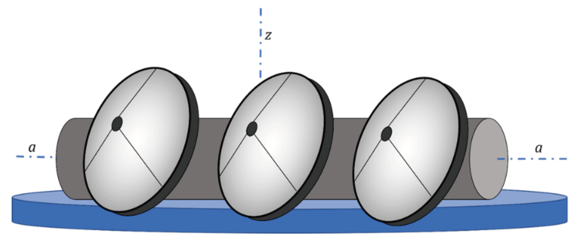
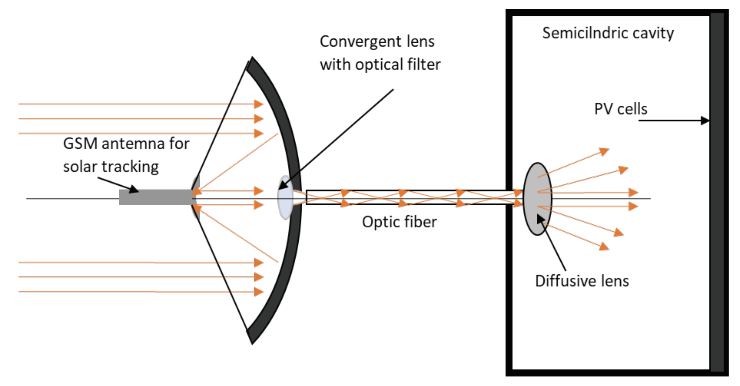
Figure 9.
Solar light trapping system for illuminating, with filtered light, photovoltaic cells enclosed in a semicylindrical chamber with reflective inner walls. This prevents the heating of the photovoltaic panel by rays of frequencies that do not allow the creation of electron-hole pairs; the PV cells themselves are protected from the atmospheric elements.
Disclaimer/Publisher’s Note: The statements, opinions and data contained in all publications are solely those of the individual author(s) and contributor(s) and not of MDPI and/or the editor(s). MDPI and/or the editor(s) disclaim responsibility for any injury to people or property resulting from any ideas, methods, instructions or products referred to in the content. |
© 2025 by the authors. Licensee MDPI, Basel, Switzerland. This article is an open access article distributed under the terms and conditions of the Creative Commons Attribution (CC BY) license (http://creativecommons.org/licenses/by/4.0/).
Copyright: This open access article is published under a Creative Commons CC BY 4.0 license, which permit the free download, distribution, and reuse, provided that the author and preprint are cited in any reuse.


