
Submitted:
06 January 2025
Posted:
07 January 2025
You are already at the latest version
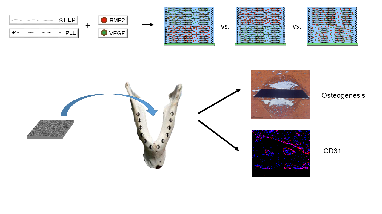
Abstract
The aim of the present study was to test the sequential and simultaneous release of rhBMP2 and rhVEGF165 from poly-l-lysine-heparin (PLL-Hep) polyelectrolyte multilayer (PEM) coating on titanium surfaces for their ability to enhance periimplant bone formation and CD31 expression around disc shaped titanium implants (5 x 7 mm) in minipig mandibles. Bare titanium surfaces loaded with respective growth factor combinations served as controls. Ten different surface conditions were tested exhibiting early VEGF release, early BMP release, simultaneous VEGF and BMP release and sole VEGF / BMP release, respectively. The implants were inserted press-fit into 5 mm trephine cavities at the lower border of the mandibles of minipigs and left to heal for 4 and 13 weeks. After 4 weeks, there was no significant difference in periimplant bone formation, bone-implant-contact nor CD31 expression between the different surface conditions. After 13 weeks, bone formation was significantly higher in the zone of 100 µm next to implant surfaces releasing either BMP alone or with an early release of BMP2. Expression of CD31 has significantly decreased from 4 to 13 weeks with significantly higher values in the group of implants with early release of BMP2. The results indicate that the range of released growth factors is limited to a distance of appr. 100 µm and that the sequence of early release of BMP2 followed by VEGF165 promotes periimplant bone formation and periimplant angiogenesis, which is in contrast to the current understanding of the temporal patterns of growth factor release for enhancement of bone formation.
Keywords:
Heparin polyelectrolyte multilayer
; bone morphogenic proteins
; vascular endothelial growth factor
; controlled release
; biofunctionalization
1. Introduction
Titanium implants are widely used for the fixation of various devices to the surrounding or underlying bone. Formation of new bone tissue around the endosseous implant parts is a biological key process for the anchorage of the implant surface in viable bone. However, systemic or local conditions may deteriorate the ability of the periimplant environment to form bone of sufficient quality or quantity to accomplish this process of osseointegration [1,2,3]. Various approaches have been used to enhance the biological quality of titanium implant surface [4,5,6,7]. One of the frequently explored avenues improving the biological interaction between the implant surface and the periimplant bone has been the binding and release of biologically active substances such as growth factors [8,9,10,11]. Unfortunately, adsorptive coating of the bare metal surface with growth factors has been associated with a very rapid release of high dosages, leading to untoward effects with respect to osseointegration [12,13,14,15]. Strategies for more sophisticated binding and release of biologically active signals encompasses surface engineering using single layers of anchoring molecules as well as multilayer coatings of various compositions [16,17,18,19,20]. In particular, the use of polyelectrolyte multilayers employing glucosaminoglycans (GAGs) has been shown to be able to accommodate growth factors in the µg range with a release kinetic of several weeks [21,22,23]. The advantage of using GAGs as polyanions is the naturally occurring interaction with proteins, which is particularly true for Heparin that additionally provides binding sites for many polypeptide growth factors involved in osteogenesis such as bone morphogenic proteins (BMPs) and vascular endothelial growth factor (VEGF) [24].
The layer-by-layer approach of multilayer film constructions on the one hand allows for the modulation of release kinetics of growth factors by additional cross-linking of the polyelectrolyte chains [21,23,25,26]. On the other hand, it can be used for a targeted incorporation of individual growth factors in different layers, thereby giving rise to a differential pattern of release in terms of sequence and dosage. Recent work has shown that variations in the architecture of polyelectrolyte multilayer coatings of poly-l-lysine (PLL) and heparin (Hep) as well as the location of growth factors within the films is important for the amount of the individual growth factor released. Thereby, the osteogenic and angiogenic properties of these modified surface variations could be modulated in a targeted manner [27,28].
It was thus the aim of the present study to assess the biological effect of an array of modifications of PLL-Hep multilayer coatings on microrough titanium surfaces loaded with osteogenic and angiogenic growth factors. Titanium discs were coated with PLL-Hep multilayer films and loaded with rhVEGF165 and rhBMP2 in different layers within the multilayer film. The square discs were inserted a large animal model in minipig mandibles and evaluated for their angiogenic activity as well as for periimplant bone formation and the degree of osseointegration.
2. Materials and Methods
2.1. In Vitro Study
2.1.1. Titanium Specimen Fabrication
[Square titanium discs of 7 x 5 mm (cpTi) discs with a thickness of 1 mm were sandblasted and acid-etched (KLS Martin, Tuttlingen, Germany) as previously described [18] in 5.1 M hydrochloric acid and 4.6 M sulphuric acid solution for 300 s by 108 °C. The discs had a trapezoid profile to provide a sharp cutting edge on both sides for press-fit insertion into trephine holes (see below).
2.1.2. Multilayer Coating of Ti Discs
Chemicals and reagents were purchased from Sigma-Aldrich (Taufkirchen, Germany) and used without further purification, unless stated otherwise. For fabrication of PEM films, poly-l -lysine (30 – 70 kDa) and heparin (50 mg/ml, from porcine intestinal mucosa, sulfate content 2.7/monomer, specific activity ≥ 180 USP units/mg, molecular weights of polyanion chains ranging from 6 kDa – 30 kDa, with most chains in the range of 17 - 19 kDa) were dissolved in Na-acetate buffer (20 mM, pH 4.5) at a concentration of 1 mg/ml. Films were constructed semi-automatically using a dipping robot (DR3, Riegler&Kirstein, Germany). First, the cleaned substrates were soaked into the polycation solution (PLL) and left there for 5 min until an adsorption equilibrium was established. Subsequently the samples were washed three times in deionized water to remove unbound polyelectrolytes. Heparin was adsorbed alike by an incubation for 5 min followed by three rinsing steps. The film construction was performed by repeating these cycles until reaching the desired number of double layers and film architecture, respectively. All samples were rinsed in deionized water and air dried in a gentle stream of pressurized air.
2.1.3. Variation in Film Architecture and Growth Factor Loading
Five combinations of film architecture and loading patterns with rhBMP2 / rhVEGF165 were produced on the Ti discs:
- a)
- One (PLL-Hep)20 multilayer system that was loaded with a rhBMP2 (20-rhBMP2);
- b)
- One (PLL-Hep)20 multilayer system that was loaded with rhVEGF165 (20-rhVEGF165)
- c)
- Two subsequent (PLL-Hep)10 multilayer systems for dual growth factor loading using a two-step procedure: a (PLL-Hep)10 multilayer system was loaded with one growth factor, after which a second (PLL-Hep)10 multilayer system was added with subsequent loading of the second growth factor on top (10-rhBMP2-10-rhVEGF165).
- d)
- This procedure was modified by changing the sequence of growth factor loading (10-rhVEGF165-10-rhBMP2).
- e)
- One (PLL-Hep)20 multilayer system that was loaded with both growth factors together (20-rhBMP2+rhVEGF165).
Titanium discs with unloaded (PLL-Hep)20 multilayer coatings as well as uncoated bare Ti discs with adsorptive loading with a single growth factor (rhBMP2, rhVEGF165) and two growth factors (rhBMP2 & rhVEGF165) served as controls. This resulted in 10 different surface conditions to be tested (Table 1). Discs were evaluated in vitro for the amount of growth factor incorporated and released and in vivo for the amount of periimplant bone formation and the degree of osseointegration. Moreover, expression of CD31 was evaluated as angiogenic marker using immunofluorescence microscopy.
2.1.4. Growth Factor Loading/Samples for In Vitro Release
For in vitro release testing the titanium discs were placed into 3D-printed silicone mounts in groups of three discs exposing only one side of the disc and were dipped overnight in 160 µl of a loading solution with either rhBMP2 (75 µg/ml; Chinese Hamster Ovary cell-derived, PeproTech, Hamburg, Germany) or rhVEGF165 (75 µg/ml; Human Embryonic Kidney 293 cell-derived, ThermoFischer, GIBCO, Darmstadt, Germany), corresponding to 3 µg per specimen. The discs with dual growth factor loading were first incubated with rhVEGF165 followed by rhBMP2. The concentrations of growth factors in the loading solutions for rhBMP2 and rhVEGF165 had been defined during previous experiments [28].
For the in vivo experiments, the PEM coated and uncoated titanium discs were individually loaded with growth factors on both sides. The samples were deposited into a single well each with 3D-printed silicone containers and dipped overnight in 80 µl of loading solutions with rhBMP2 (75 µg/ml; Chinese Hamster Ovary cell-derived, PeproTech, Hamburg, Germany) or rhVEGF165 (75 µg/ml; Human Embryonic Kidney 293 cell-derived, ThermoFischer, GIBCO, Darmstadt, Germany), corresponding to 6 µg growth factor per specimen reservoir. The discs with dual growth factor loading were first incubated with rhVEGF165 followed by rhBMP2.
After loading the remaining coating solutions from the individual containers / mounts were transferred to a reaction tube each for further use and the discs were washed twice with deionized water and shortly air-dried at RT. The fully prepared discs were stored at 4 °C.
The amounts of rhBMP2 and rhVEGF165 bound to the multilayer systems and the bare Ti surfaces were determined indirectly from the amount growth factor contained in the loading solution using the Bicinchoninic Acid (BCA) Protein Assay Kit (ThermoScientific, Darmstadt, Germany) with bovine serum albumin (BSA) as standard according to manufacturer’s instruction. Absorbance was measured with an ELISA plate reader (SpectraMax M2, Molecular Devices, San Jose, CA, USA) at 562 nm, RT. All samples were measured in duplicate.
In case of dual loading with growth factors, the supernatant from the second loading procedure was tested for a possible eluation of the first loaded growth factor during the second loading using the BMP2 or VEGF enzyme-linked immunosorbent assay (ELISA), respectively, as described below. The specificity of the ELISAs were tested. Only absorption or between 0.06 – 0.89 % of the determined amount of the first loaded on the discs growth factor were detected.
2.1.5. Release Experiments
All growth factor loaded titanium discs were placed into 24-well plates and incubated in 250 µl DMEM supplemented with 2 % FCS and 1 % penicillin/streptomycin at 37 °C in a 5 % CO2 atmosphere, shaking at 70 rpm (Celltron, InforsHT, Einsbach, Germany). The medium was collected and replaced after 24, 48, 72 h and every 3 days thereafter until day 21. The supernatants were stabilized with protease inhibitor (ROCHE Diagnostics, Mannheim, Germany). The release profiles of rhBMP2 and rhVEGF165 were assessed using Human/Murine/Rat BMP2 and Human VEGF Standard TMB ELISA Development Kit (PeproTech, Hamburg, Germany), respectively, according to the instructions of the supplier. RhBMP2 (PeproTech) or rhVEGF-165 (ThermoFisher, Gibco) were used as standard. Absorbance was measured with an ELISA plate reader (SpectraMax M2) at 450 nm with wavelength correction set at 620 nm. All measurements were done in duplicate on three specimens each.
2.2. In Vivo Study
2.2.1. Sample Size Calculation
The ten different surface conditions were planned to be evaluated after 4 and 13 weeks each. In order to maintain a Family-Wise-Error-Rate of 5 % across the comparisons, each comparison was be performed at level of significance of α = 5 %/14 = 0.36 %. A detectable difference in bone formation / degree of osseointegration was assumed to be relevant at an increase by 10 % starting from 10 % with a standard deviation of 10 % per interval / surface condition. In order to detect this increase as significant at an assumed standard deviation of σ=10% within the groups at a significance level of α = 0.36 % and a power of 1-β = 80 %, a group size of 6 animals was calculated.
2.2.2. Surgical Procedures and Animal Care
A mini pig model was chosen as the bone biology in these animals compares well with human biology [29]. According to the sample size calculation 12 animals were used (gender: female; age: 2 - 3 y, weight 44.6 ± 7.6 kg). The animals were randomly allocated to two groups of six animals each for evaluation after 4 weeks and 13 weeks, respectively. All surgical procedures, housing and animal care were carried out in accordance with the German legislation for animal protection and the regulations for animal experiments of the state of Lower Saxony. The trials were reported and admitted under the license number 20/3554. Animals were held in groups of 2 – 3 animals in cages with concrete floor with saw dust bedding and wooden walls. They were allowed to accommodate for four weeks prior to the beginning of the clinical procedures. All animals presented in good health. [All surgical procedures were conducted in the animal facilities of the University Medicine Goettingen following the ARRIVE guidelines [30]. The experiments were conducted between 02/2022 and 06/2022. Sedation and anesthesia as well as the postoperative care were executed by qualified veterinarians. Initially, a dose of 0.5 mg/kg body weight of Diazepam was administered orally followed by intramuscular injection of 10 mg/kg body weight Ketamine and 2 mg/kg body weight Azaperone after approximately 20 minutes. An intravenous catheter was then applied and general anesthesia was induced with titrated Thiopental until intubation was possible. Anesthesia was maintained using 2 % - 4 % of Isoflurane, supported by Piritramid and Ketamine to add analgesic capacity. Eyes were covered with a Dexpanthenole lotion (Bepanthen©, Bayer AG, 51368 Leverkusen, Germany).
A bilateral submandibular approach was chosen for surgical access to the mandible. Trephine holes of 5 mm diameter and 5 mm depth were created at the lower border of the mandible with vertical bone cuts of 0.5 mm depth at the mesial and distal side created with a fissure burr (Figure 1). The setting included four more groups with different experimental surface conditions that will be reported elsewhere (Kauffmann et al. 2025 in preparation).The discs were placed press fit into the trephine cavities. The allocation of the individual position of the different surface modifications to the trephine drill holes along the mandibular border was defined by drawing lots. Subsequently, the periosteum overlying the opening of the cavity was removed to exclude bias in bone formation due to excessive periosteal bone regeneration and wounds were closed in layers using resorbable sutures (Vicryl 3.0, Ethicon, Norderstedt).
During the immediate postoperative period (1 week) of both series of operations, animals were visited twice per day. For reduction of postoperative pain, 0.6 mg Buprenorphin was given twice per day combined with 5 mg/kg body weight Carprofen intravenously in the first three days. If animals showed any signs of discomfort 5 – 7.5 mg/kg body weight Carprofen were administered orally. After a maximum of five days all animals were well.
2.2.3. Histologic Preparation and Morphometry
After 4 weeks and 13 weeks, the mandibles of 6 animals each were retrieved and the implanted discs with surrounding bone were removed using a diamond saw (EXAKT©, Robert-Koch-Str. 5, 22851 Norderstedt, www.exakt.de) followed by dehydration and embedding into Technovit 9100© (Heraeus Kulzer GmbH, Philipp-Reis-Str. 8/13, 61273 Wehrheim, Germany). Thick-section specimens [31] were produced from each disc and its surrounding bone in a plane parallel to the edge of the longer side of the discs starting from the lower border of the mandible in upward direction. The resulting specimens were surface stained using both Toluidin blue and Alzarine-Methylene Blue. For histomorphometry, the trephine defect area as a whole was evaluated separately from the area adjacent to the implant surface. The periimplant zone was defined as a 300 µm thick layer and was divided into 3 layers of 100 µm thickness each on both sides of the implant cross section, creating an i) immediate, ii) intermediate and iii) remote tissue layer in relation to the implant surface. Each layer was divided into three sections: i) one central third and ii) two peripheral thirds next to the wall of the trephine cavity on both sides. This resulted in 18 distinct areas of periimplant tissue allowing to assess the effect of distance from the implant surface and distance from the cavity walls on the efficacy of released growth factors on periimplant bone formation and bone anchorage.
For morphometric evaluation, specimens were scanned using a digital scanning device (Dotslide-System2.0©, Olympus Deutschland GmbH, Wendenstraße 14-18, 20097 Hamburg, Germany). The resulting digital image data were analysed using a custom-made Python3 based image analysis pipeline utilizing the common Python modules scikit-image, matplotlib, opencv and pandas.
Primary outcome parameters were:
- i)
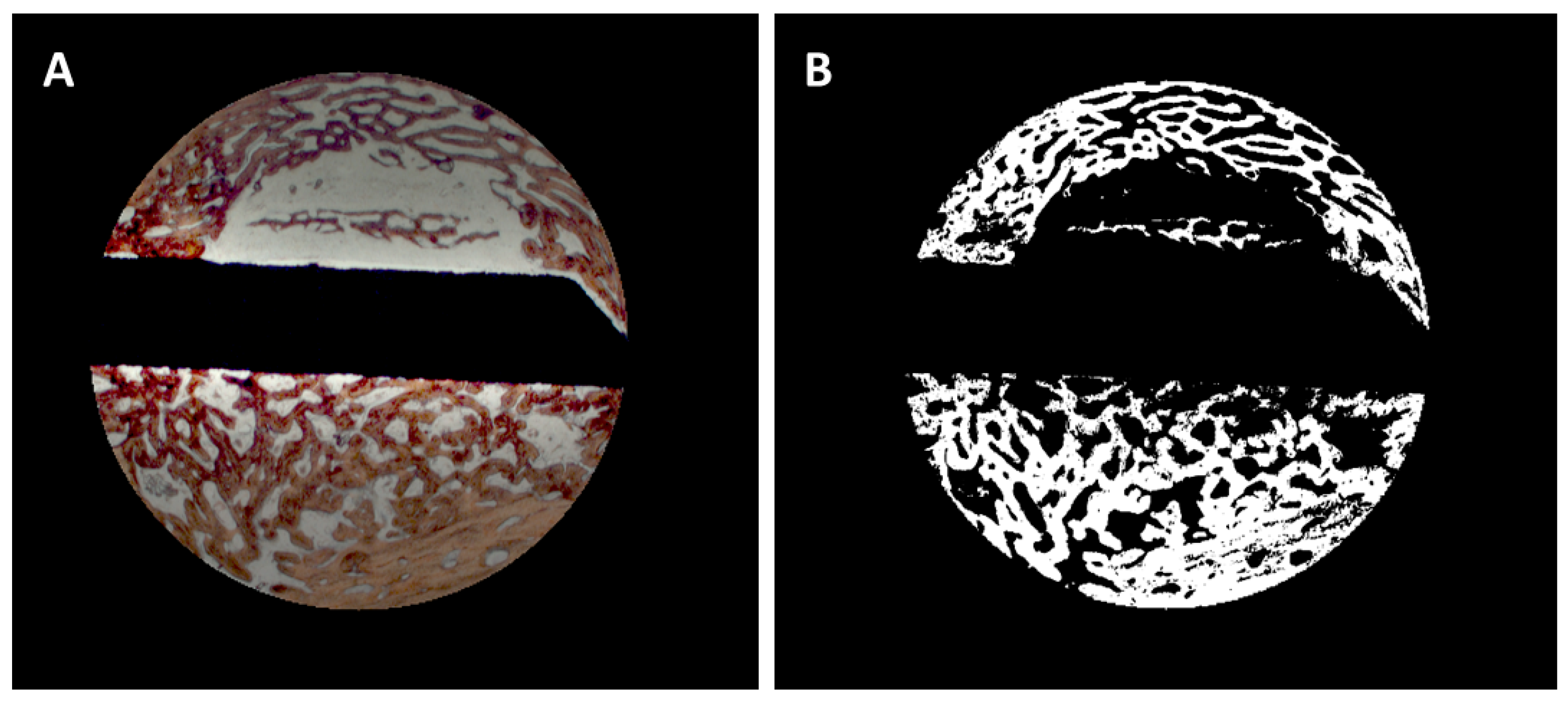
- Bone area / bone density: the algorithm automatically identified the color of the Alizarine Red stained areas in the cross-section specimens and assessed the area occupied by bone both in absolute values (bone formation (BF)) and in in relation to each section area (bone density (BD)) by pixel counting. Pixels were converted in mm² using the calculated pixel size of 17.43 µm²/pixel (Figure 2A & B). Bone density was only evaluated for the trephine defects as a whole. To account for variations in the appearance of the color of Alizarine Red in the different and in cases in which the new formed bone covered the entire trephine defect, parameters were manually adjusted.
- ii)
- Bone implant contact (BIC). The algorithm identified the surface area occupied by bone by image analysis routines and calculated the bone-implant-contact (BIC) as percentage of occupied surface area. In brief, the surface of the identified cross-section of the implant was enlarged by 1 pixel (approx. 4.18 µm) and limited to the trephine defect size. The resulting mask was multiplied with the bone mask and the ratio of those pixel to the entire surface of the implant was calculated.
Figure 2.
A: Selection of the trephine defect for morphometric evaluation, B: Digitization of the bone area.
Figure 2.
A: Selection of the trephine defect for morphometric evaluation, B: Digitization of the bone area.
Measurements were performed by one blinded examiner, who was calibrated during introduction to the image analysis system. Outcome parameters were assessed individually for each cross-section, mean values were calculated for each disc from 3 – 4 cross-sections.
2.2.4. Immunohistochemical Preparation and Evaluation of Immunofluorescence
Technovit embedded thick-section specimens (see Histologic preparation and morphometry) were mounted on glass slides (Paul Marienfeld GmbH, Lauda-Koenigshofen, Germany). After preparation of tissue sections with a resulting thickness of 70-100 µm the sections were incubated three times with xylene, 20 min each and placed three times (twice for 20 min and once overnight) in MEA (2-methoxyethylacetate, Merck, Darmstadt, Germany). The specimens were then rehydrated in descending concentrations of ethanol (100 %, 96 %, 70 %, twice for 2.5 min each) and washed twice in deionized water for 2.5 min each.
For the immunofluorescence staining, the deplasticized and rehydrated bone tissue sections were incubated in 1x citrate-based TR buffer, pH 6.0 (Target Retrieval Solution, Agilent Dako, Waldbronn, Germany) for 30 sec at 121°C followed by incubation for 10 sec at 90°C using a standard pressure cooker (PASCAL S2800, Dako, Hamburg). Subsequently, the sections were incubated for 5 min at room temperature (RT), washed for 10 min in deionized water and lastly washed three times in PBS for 5 min each. Next, the samples were incubated for 1 h at RT in blocking buffer (10 % goat Serum Block in PBS, Histoprime Biozol, Eching, Germany). For the detection of CD31, the specimens were incubated with an anti-CD31 antibody (CD31/PECAM1, Platelet/endothelial cell adhesion molecule-1, ABIN 726140, 1:100; antikoerper-online.de, Aachen, Germany) at 4 °C overnight. After washing three times in PBS, 5 min each, the specimens were labeled using the secondary antibody Alexa Fluor 647 (ab 150079, 1:500; Abcam, Cambridge, UK) by incubation for 1 h at RT followed by washing three times in PBS for 5 min each. Subsequently, nuclei were counterstained with DAPI (1:1000; Sigma-Aldrich Merck, Darmstadt, Germany) for 10 min at RT. Finally, the sections were washed in PBS (three times, 5 min each) and mounted with Fluor Save Reagent (30 min at RT and overnight at 4°C; Merck Millipore, Darmstadt, Germany).
The antibodies and DAPI were diluted using Antibody Diluent (Agilent Dako, Waldbrunn, Germany). All incubations, including blocking, were performed in a humidity chamber.
After immunostaining, the specimens were analyzed with the KEYENCE BZ-X710 microscope (Keyence, Neu Isenburg, Germany) using a Cy5 filter (OP-87766) for detection of the target protein CD31 and the DAPI filter (OP-87762). Sections stained without the primary antibody served as controls. One cross sectional specimen of each surface condition per animal was evaluated. Quantitative analysis was performed on digital images of the specimens at 20-fold magnification corresponding to an image size of 725 x 543 µm displaying the implant surface at the lower border of the field of view and periimplant tissue up to a distance of approximately 400 µm thickness. Thirteen images, placed on the upper (7) and lower (6) edge of the cross sections were analyzed. Quantification of CD31 expression was measured in µm² using the BZ-X-Analyzer tool filter for red light, overlay images with DAPI stained nuclei were used for analysis (Figure 3 A through D).
2.2.5. Statistics
Data are presented as means ± standard deviation (SD). Friedman tests (SPSS Statistics 26.0, http://support.spss.com) were used to compare bone formation (BF), bone density (BD) and bone-implant contact (BIC) as well as expression of CD31 between the experimental surfaces. Additional Wilcoxon tests were used for pairwise comparison. All test were performed at a significance level of 5 %.
3. Results
3.1. In Vitro Experiments
3.1.1. Growth Factor Loading
Loading of the (PLL-Hep)20 films with rhVEGF165 and rhBMP2 alone lead to incorporation of comparable of 4.4 µg (SD 2.0) VEGF and 5.7 µg (SD 0.4) BMP per cm² surface, respectively (Table 1). Loading of the (PLL-Hep)10 films with rhBMP2 first and subsequent build-up of an additional (PLL-Hep)10 film followed by loading with rhVEGF165 resulted in incorporation of less rhBMP2 (3.8 µg (SD 1.3)) and more rhVEGF165 (5.5 µg (SD 0.4)). When the sequence was swapped with rhVEGF165 in the lower film system and rhBMP2 in the upper, comparable amounts of growth factors were loaded into both film systems (rhBMP2: 5.9 (SD 0.6); rhVEGF165: 5.0 (SD 0.7). Loading of rhBMP2 and rhVEGF165 in the same (PLL-Hep)20 film resulted lower loading of rhBMP2 (3.5 µg (SD 1.5) than rhVEGF165 (4.5 µg (SD 2.1). Loading of bare Ti surfaces with rhBMP2 alone resulted in lower amounts of growth factor bound to the surface when compared to the PLL-Hep film coated discs whereas loading with rhVEGF resulted in adsorption of comparable amount of growth factor as loading of (PLL-Hep)20 films.
3.1.2. Growth Factor Release
During the 21 days interval of in vitro release, the films with a 2-zone architecture with sequential loading of rhVEGF165 and rhBMP2 into (PLL-Hep)10 films each released minimal amounts of rhBMP2, when it was incorporated into the lower zone (0.06 µg/cm² surface, SD 0.01), compared to the release from the same films loaded with rhBMP2 alone (2.59 µg, SD 0.43) (Table 2). In contrast, the release of rhVEGF165 from the upper layer of the 2-zone architecture was higher than from of the (PLL-Hep)20 films loaded with VEGF alone (2.63 µg, SD 0.27 vs. 1.70 µg, SD 0.28). This was reversed when the location of the growth factors was swapped with a slightly increased release of rhBMP2 from the upper zone of 3.03 µg (SD 0.47) compared to loading with rhBMP2 alone (2.59 µg, SD 0.43), whereas the delivery of rhVEGF165 was almost completely suppressed (0.01 µg, SD 0,001) during the observation period. When both growth factors were loaded together into one (PLL-HEP)20 film, the release of rhBMP2 and rhVEGF165 was at an equal level of 1.96 µg (SD 0.28) and 1.49 µg (SD 0.29) respectively. Release from the bare metal surfaces rhBMP2 and rhVEGF165 loading alone produced 0.27 µg VEGF (SD 0.02) and 0.36 µg BMP (SD 0.03). Discs with combined loading with both growth factors released 0.89 µg rhBMP2 (SD 0.66) and 0.16 µg of rhVEGF165 (SD 0.05) on average during the observation period.
3.2. In Vivo Experiments
Postoperative healing was uneventful. No animal was removed from the evaluation. Analgesic therapy could be stopped after postoperative 5 days. All 12 animals were included into the evaluation. During preparation of the specimens, it became obvious that one disc with a (PLL-Hep)20 multilayer system that was loaded with rhVEGF165 only had been lost. All other 167 discs could be submitted to the scheduled morphologic and quantitative evaluation.
3.2.1. Histology
4 weeks: Little bone formation was observed after 4 weeks originating from the trephine defect walls (Figure 4). Sparce bone trabeculae were seen in contact with the surface of the disc implants. In some defects, trabecular bone formation had occupied more volume, however, this was not associated with a specific coating or growth factor loading.
13 weeks: Substantially increased bone formation was seen after 13 weeks that almost completely filled the defect volume in some specimens, again without being associated with a certain surface condition or growth factor loading. The predominant pattern of immediate periimplant bone regeneration was characterized by a propagation along the implant surfaces with bone formation originating from the defect walls (Figure 4). Surfaces with early release of BMP-2 exhibited a higher degree of osseointegration with more complete coverage of the implant surface by newly formed bone.
3.2.2. Histomorphometry
4 weeks:
Bone formation: After 4 weeks, bone formation in the trephine defects ranged between 4.23 mm² ((PLL-Hep)20/VEGF+BMP2) and 5.79 mm² (uncoated Ti discs loaded with VEGF) with no significant differences between the experimental surface conditions and the controls (p=0.733) (Figure 5). Bone density varied between 18.3 % (2-zone architecture with VEGF on top and BMP below) and 26.8 % (uncoated Ti discs, loaded with BMP) without significant differences (p=0.676). Bone regeneration in the three periimplant zones (immediate, intermediate and remote layer) was considerably lower compared to the whole defect volume with amounts of bone formation varying between 0.04 mm² and 0.36 mm² and bone density ranging between 2.5 and 16.5 %. As with the trephine defects as a whole, no significant differences were found in the individual zones between the multilayer coatings loaded with BMP with or without VEGF and the respective control surface conditions (p=0.131, p=0.063, p=0.111, respectively) (Figure 6). The same held true when the central parts and the peripheral parts of the periimplant zone immediate to implant surface where considered (p=0.079 and 0.285, respectively) (Figure 7).
Bone-Implant contact: Bone implant contact after 4 weeks showed considerable variation between the different surface groups ranging between 2.1 % ((PLL-Hep)20 with VEGF loading) and 7.1 % (uncoated Ti discs loaded with BMP) (Figure 8). No significant differences were found between the multilayer coating loaded with growth factors and the respective controls (p = 0.741).
13 weeks:
Bone formation: After 13 weeks, the area of newly formed bone in the trephine defects varied between 11.6 mm² (2-zone architecture with BMP on top and VEGF below) and 13.7 mm² (uncoated Ti discs, loaded with VEGF) (Figure 5). The same held true for bone density of the regenerated bone within the trephine defects (p=0.381) with values ranging between 56.2 % ((PLL-Hep)20 loaded with VEGF) and 64.3 % ((PLL-Hep)20 loaded with BMP) (Figure 5). When the three periimplant zones were considered, the average area of newly formed bone was not significant different between the various surface conditions in the intermediate and the remote layer. When the immediate surface layer was analyzed, the largest area of bone formation in this zone was found in group of implants coated the (PLL-Hep)20 loaded with BMP (1.75 mm²) and implants with a 2-zone (PLL-Hep)10-architecture with VEGF the lower zone and BMP in the upper zone (1.59 mm²). Mean values of these two groups were significantly higher than the uncoated titanium controls (p=0.046 for both groups), whereas the remaining surface modifications failed to show significant differences compared to the uncoated / unloaded Ti controls (Figure 6). When the immediate periimplant zone next to the implant surface was considered separately for the central and the peripheral parts of the implant surface, a significant difference in bone formation between the different surface conditions was found only in the central (p=0.016) but not in the peripheral parts (p=0.186). In the central part, pairwise comparison with Ti controls showed a significant increase in bone formation only for implants coated with a 2-zone (PLL-Hep)10-architecture with VEGF in the lower and BMP in the upper zone (p=0.046) (Figure 7).
Bone-Implant contact: Bone implant contact after 13 weeks showed corresponding results to the amount of bone formation in the immediate surface layer. The highest rate of bone implant contact was found in the groups of implants coated with (PLL-Hep)20 loaded with BMP (57.9 %), the lowest in implants with a 2-zone (PLL-Hep)10-architecture with BMP the lower zone and VEGF in the upper zone (29.8 %) (Figure 8). Statistical analysis showed significant differences between the uncoated / unloaded Ti controls and i) implants coated with (PLL-Hep)20 loaded with BMP (p=0.046), ii) implants coated with a 2-zone (PLL-Hep)10-architecture with VEGF the lower zone and BMP in the upper zone (p=0.028) and iii) implants coated with (PLL-Hep)20 loaded VEGF and BMP together (p=0.046). Implants coated with (PLL-Hep)20 loaded with BMP only exhibited also a significantly higher BIC than implants with bare Ti surfaces loaded with BMP (p=0.046). All other surfaces were not significantly different to the uncoated / unloaded controls. Moreover, there was no significant difference between the BMP releasing surfaces.
3.2.3. Immunofluorescence of CD31 Expression
4 weeks: After 4 weeks, CD31 expression was strongest immediately adjacent to the implant surface of implants loaded with growth factors. There was no clear distinction between surfaces releasing BMP2, VEGF165 or both. The soft tissue overlying the implant surface exhibited a diffuse distribution of CD31 expression across the captured thickness (Figure 9). Titanium controls did not show the stronger positivity of CD31 expression immediately adjacent to the implant surface.
13 weeks: Expression of CD31 was much more confined to structural elements of the periimplant tissues such as perivascular tissue or osteoid seams lining bone trabeculae. Implants with bare titanium surface showed only sparce positivity for CD31 (Figure 10).
3.2.4. Histomorphometry of Immunofluorescence of CD31 Expression
4 weeks: After 4 weeks, the area of expression of CD31 varied between 6.9 and 30.5 x 10³ µm² (Figure 11). Differences between the individual surface conditions were highly significant (p=0.004). Discs with a 2-zone architecture with BMP on top and VEGF below and vice versa as well as discs with dual growth factor loading exhibited the highest mean values that were partially significantly different when compared to discs with PLL-Hep-coating and single growth factor loading and significantly higher when compared to unloaded PLL-Hep coated discs (Table 3). Discs with bare Ti surfaces loaded with growth factor exhibited significantly higher mean values compared to unloaded Ti discs (Figure 11). Differences between discs with PLL-Hep coating and growth factor loading and discs with growth factor loaded bare Ti surfaces were not significant.
13 weeks: After 13 weeks, the expression of CD31 in periimplant tissues had decreased for all surfaces resulting in a range between 4.9 and 22.4 x 10³ µm³ (Figure 9). This decrease from 4 weeks to 13 weeks was significant for all discs with growth factor loaded bare Ti surfaces (p=0.002 for VEGF-BMP as well as BMP only loading and p=0.009 for VEGF only loading). Moreover, discs with PLL-Hep coating with early VEGF release (2-zone architecture with VEGF on top and BMP below) or VEGF only release exhibited a significant decrease (p=0.041 and 0.004, respectively). The highest mean values have been found in the group of discs with a 2-zone architecture with BMP on top and VEGF below. This was significantly higher than mean values of the other two PLL-Hep coated discs with dual growth factor loading (p=0.028 for both comparisons). Moreover, all except one comparisons between dual growth factor loaded PLL-Hep surfaces and PLL-Hep surfaces with single growth factor loading exhibited significantly higher mean values than the corresponding Ti controls (Table 4). Differences between uncoated Ti surfaces with growth factor loading exhibited no significant differences when compared to the unloaded control Ti surface.
4. Discussion
The present study has assessed the effect of dual growth factor loading of a poly-electrolyte multilayer (PEM) coating of titanium implants on periimplant bone formation and bone-implant contact as well as the level of angiogenic activity. Heparin had been chosen as polyanion as it is a naturally occurring component of the intercellular matrix and a large number of polypeptide growth factors provide binding sites for heparin (Ishihara et al. 2017). Previous in vitro work had shown that variations in Heparin-PEM film architecture with differential loading of rhVEGF165 and rhBMP2 had been able to modify the angiogenic and osteogenic properties in a targeted way (Behrens et al. 2022). In the present study, the in vitro pattern of release of BMP and VEGF had confirmed that the 2-zone architecture has produced an early angiogenic / osteogenic activity of the experimental surfaces depending on the growth factor located in the upper zone, whereas the growth factor in the lower zone did not contribute to the biological activity during this early period. A simultaneous combination of both angiogenic and osteogenic activity was only achieved when the films were loaded with BMP and VEGF together. The idea behind this approach has been to evaluate the effect of early angiogenic vs. osteogenic activity independently by delivery of the superficially located growth factor during the initial period of bone healing followed by a late release of the complementary activity during continuing eluation or degradation of the PEM films and to compare this sequence with a continuous combined angiogenic and osteogenic activity early on. The modification of the temporal pattern of release from multilayers loaded with multiple growth factors has been approached previously using barrier layers of biomimetic Ca-Phosphate [32,33] or intervening layers of poly-acrylic acid, laponit or chitosan [34,35,36]. The isolating effect of these integrated barriers has been reported to delay the release of the second biological factor by 3 – 70 days [33,34,35] or reduce the percentage of growth factor release without changing the temporal pattern of release [36]. A comparable approach to the 2-zone PEM film architecture in the present study has been used by Shah and coworkers employing up to 120 tetralayers containing rhBMP2 covered by up to 80 tetralayers containing rhVEGF165. Poly-aminoester had been used as polycation combined with poly-acrylic acid as polyanion for the BMP containing lower zone and condroitinsulfate for the VEGF loaded upper layers. This had resulted in a slightly delayed release of rhBMP2 from the lower layers compared to the immediate release of VEGF from the upper zone [27]. In the present study, the isolating effect of a second zone of only 10 bilayers PLL-Hep on top of the growth factor loaded zone of 10 bilayers below has been suitable to suppress the release from the lower zone for at least 3 weeks. One possible reason for the long-lasting retarding effect of this rather low number of overlying double layers may be the fact that heparin has a higher specific affinity for growth factors than many other anionic partners in PEMs and is a strong polyelectrolyte pairing partner for PLL, which reduces the diffusivity of PEMs thereby decreasing the release from deeper layers of the constructed PEM film [37].
The quantitative in vivo results have shown that an effect of the bioactive coating on bone regeneration was not visible when the total volume of the trephine defect was considered. However, when the three periimplant zones were analysed separately, it became obvious that significant differences occurred in the zone immediately adjacent to the implant surface indicating that the range of growth factors released from the implant surface was limited to a distance of approximately 100 µm in the present model. Out of the experimental surfaces only those implants with an early osteogenic characteristic have shown a significantly increased formation of new bone compared to the uncoated / unloaded titanium controls in this zone, whereas surfaces with an early angiogenic release profile did not significantly increase bone formation in the immediate periimplant zone. When the analysis was focussed even more to the central section of the implant, surfaces with rhBMP2 loading alone and those with the 2-zone architecture with rhBMP2 in the upper coating zone showed significantly increased bone formation that was even significantly higher than the uncoated Ti surface loaded with rhBMP2 and rhVEGF165.
The expression of CD31 as a measure for angiogenic activity in the present study has shown a differential pattern of biological response to the in vitro assessed release profile of both growth factors. At the early interval of 4 weeks, there was no significant difference in CD31 expression between the response to the loaded respective growth factors on PLL-Hep coated surfaces vs. the bare Ti surfaces. Both loading approaches have shown a significant increase over the respective control surfaces albeit a differential effect of the retarded release from the PLL-Hep coated surfaces compared to the bare Ti surfaces has not been appreciable at this time. This was different in the 13 weeks interval, where the CD31 expression in the periimplant tissues was significantly decreased in the groups of bare Ti surfaces to the level of the Ti control surface, indicating that the biological effect of this loading approach has ceased. In the groups of PLL-Hep coated surfaces distinct differences could be seen depending on the architecture and growth factor loading of the polyelectrolyte films. The surfaces with an early BMP2 release from the top layers of the 2-zone architecture or with a continuous release of BMP2 with or without simultaneous VEGF165 release maintained a level in CD31 expression after 13 weeks that was not significant from to that after 4 weeks. In contrast, surfaces with early VEGF release from the top layers of the 2-zone architecture or sustained VEGF only release have shown a significant decrease in the levels of periimplant CD31 expression from 4 to 13 weeks that nevertheless were still significantly higher than the unloaded PLL-Hep control surfaces. Moreover, looking at the BMP2 releasing surfaces, a differential effect of the early BMP2 release from the upper zone of the 2-zone architecture with VEGF165 in the lower zone was visible with a significantly higher level of CD31 expression compared to surfaces with simultaneous BMP2 / VEGF165 release and the 2-zone architecture with early release of VEGF165 from the upper zone.
These findings indicate on the one hand, that the biological activity of the growth factors released from the PLL-Hep multilayer films in the present study has been substantially sustained compared to the adsorptive coating of the bare Ti surfaces for at least 3 months. On the other hand, they suggest that an early and continued release of BMP2 supported by a later release of VEGF165 leads to a higher level of angiogenic activity than a simultaneous release of both growth factors or an early release of VEGF with or without by a later release of BMP2. This increased expression of CD31 is paralleled by a significantly increased bone volume in the group with early BMP release.
Looking at the sequence of angiogenic and osteogenic activities, the results of the present study appear to be in contradiction to the common appreciation that angiogenesis would preceed osteogenic activity in order to provide inducible perivascular cells that subsequently undergo osteogenic differentiation under the influence of ostegenic signalling. The present results suggest that an initial osteogenic impulse through a pleiotrophic growth factor such as BMP2 [38,39] is more advantageous by providing a “regeneratome” [40] that is then supported by increased angiogenic signalling after a period of at least three weeks.
The activity of the released growth factors in the zone immediately adjacent to the surface is reflected also in the bone implant contact rate where all three BMP-releasing surfaces had shown a significantly increased percentage of surface area covered with bone. The confined three-dimensional range of the released growth factor has been confirmed in a recent experimental study in minipigs, where PEM film coated polymer scaffolds loaded with much higher amounts of rhBMP2 induced bone formation only in the immediate vicinity of the scaffold [41] without irregular bone formation outside the scaffold area. The same held true when ectopic bone formation was induced [27] in PEM coated polymer scaffolds loaded with comparable amounts of rhBMP2 and rhVEGF165, where bone formation was limited to the scaffold surface in a rodent model.
The generally rather low rate of bone formation in the present study compared to previous reports [27,41] may be accounted for by the experimental model where a trephine defect of 5 mm diameter is used creating an initially void space that gradually fills up with blood. Other than in three-dimensional scaffolds, biologically active signals are here presented on a two-dimensional surface with access to precursor cells originating from surrounding bone tissue that is up to 2 mm apart from the surface. Given the fact, that the range of released signals is not far beyond 100 µm, the conditions for a specific biological response would be best in the sections of the implant surface that are in contact with the walls of the trephine defect. As a consequence, formation of new bone would likely originate from the defect wall propagating along the implant surface rather being induced simultaneously in multiple spots across the surface. This is confirmed by the morphologic pattern of bone formation visible in the micrographs of the 13 week specimens.
5. Conclusions
In conclusion, the results indicate that the range of released growth factors in the present model is limited to a distance of appr. 100 µm leading to an accelerating effect on osteoconductive bone formation propagating along the implant surface from the defect walls. With respect to dual growth factor release, the sequence of early release of BMP2 followed by VEGF165 promotes periimplant bone formation and periimplant angiogenesis, which is in contrast to the current understanding of the temporal patterns of growth factor release for enhancement of bone formation.
Author Contributions
Conceptualization: P.K.,C.B.,K.L. and H.S.; methodology: P.K.,C.B.,K.L. and H.S.; software: P.S and C.D.; validation: HS; investigation: S.W., C.B:, P.S. and U.S.; visualization: C.B., U.S: and H.S.; resources: K.L. and H.S.; data curation: P.K., S.W., C.B., P.S: and U.S.; writing—original draft preparation: H.S.; writing—review and editing: P.K., S.W., C.B:, P.S:, C.D., U.S., K.L and H.S; supervision: K.L. and H.S.; project administration: K.L. and H.S.; funding acquisition: K.L. and H.S.. All authors have read and agreed to the published version of the manuscript.” Please turn to the CRediT taxonomy for the term explanation. Authorship must be limited to those who have contributed substantially to the work reported.
Funding
This work has been funded by grants from the German Research Foundation (DFG) SCHL 168-12/1 and LI 916/18-1
Institutional Review Board Statement
All surgical procedures, housing and animal care were carried out in accordance with the German legislation for animal protection and the regulations for animal experiments of the state of Lower Saxony. The trials were reported and admitted under the license number 20/3554.
Data Availability Statement
Data supporting the reported results are available as excel files on request at schliephake.henning@med.uni-goettingen.de.
Acknowledgments
The authors greatly value the help and assistance of Mr. Jens Bunzendahl, Mrs. Sigrid Ahlborn and Mrs. Ute Kant during the laboratory experiments.
Conflicts of Interest
The authors declare no potential conflicts of interest with respect to the research, authorship and/or publication of this article
Abbreviations
The following abbreviations are used in this manuscript:
| rhBMP2 | Recombinant human bone morphogenic protein 2 |
| rhVEGF165 | Recombinant human vascular endothelial growth factor 165 |
| PEM | Poly-electrolyte multilayer |
| PLL | Poly-L-Lysine |
References
- Pan J, Shirota T, Ohno K, Michi K. (2000) Effect of ovarectomy on bone remodelling adjacent to hydroxyapatite-coated implants in the tibia of mature rats. J Oral Maxillofacial Surg 58: 877-8827.
- McCracken M(1), Lemons JE, Rahemtulla F, Prince CW, Feldman D. (2000) Bone response to titanium alloy implants placed in diabetic rats. Int J Oral Maxillofac Implants 15:345-54.
- Keller JC, Stewart M, Roehm, M, Schneider GB. (2004) Osteoporosis-like bone conditions affect osseointegration of implants Int J Oral Maxillofac Impl 19: 687-694.
- Li J, Zheng Y, Yu Z, Kankala RK, Lin Q, Shi J, Chen C, Luo K, Chen A, Zhong Q. Surface-modified titanium and titanium-based alloys for improved osteogenesis: A critical review. Heliyon. 2023 Dec 18;10(1):e23779. [CrossRef] [PubMed] [PubMed Central]
- Che Z, Sun Q, Zhao Z, Wu Y, Xing H, Song K, Chen A, Wang B, Cai M. Growth factor-functionalized titanium implants for enhanced bone regeneration: A review. Int J Biol Macromol. 2024 Aug;274(Pt 2):133153. [CrossRef] [PubMed]
- Shayeb MA, Elfadil S, Abutayyem H, Shqaidef A, Marrapodi MM, Cicciù M, Minervini G. Bioactive surface modifications on dental implants: a systematic review and meta-analysis of osseointegration and longevity. Clin Oral Investig. 2024 Oct 11;28(11):592. [CrossRef] [PubMed] [PubMed Central]
- Meng HW(1), Chien EY(2), Chien HH(3). Dental implant bioactive surface modifications and their effects on osseointegration: a review. Biomark Res. 2016;4:24. [CrossRef]
- Thorey F, Menzel H, Lorenz C, Gross G, Hoffmann A, Windhagen H. (2011) Osseointegration by bone morphogenetic protein-2 an transforming growth factor beta 2 coated titanium implants in femora of New Zealand white rabbits. Indian J Orthop 45: 57-62.
- Ramanzanoglu M, Lutz R, Ergun C, Wilmowsky C, Nkenke E, Schlegel KA. (2011) The effect of combined delivery of recombinant human bone morphogenic protein-2 and recombinant human vascular endothelial growth factor 165 from biomimetic calcium-phosphate coated implants. Clin Oral Implants Res 22: 1433-1439.
- Leknes KN, Yang J, Qahash M, Polimeni G, Susin C, Wikesjö UM. (2013) Alveolar ridge augmentation using implants coated with recombinant human growth/differentiation factor 5 (rhGDF-5). Radiographic observations. Clin Oral Implants Res 24: 1185-1191.
- Mueller CM, Thorwarth M, Schmidt M, Schlegel KA, Schultze-Mosgau S. (2011) Comparative analysis of osseointegration of titanium implants with acid-etched surfaces and different biomolecular coatings. Oral Surg Oral Med Oral Pathol Oral Radiol Endod 112: 726-736.
- Beidas OE, Deschamps-Braly JC, Morgan AM, Workman MC, Knotts CD, Denny AD, El Amm CA.Safety and efficacy of recombinant human bone morphogenetic protein 2 on cranial defect closure in the pediatric population. J Craniofac Surg. 2013; 24:917-22.
- Shweikeh F, Hanna G, Bloom L, Sayegh ET, Liu J, Acosta FL, Drazin D.Assessment of outcome following the use of recombinant human bone morphogeneticprotein-2 for spinal fusion in the elderly population. J Neurosurg Sci. 2014.
- Merrick MT Hamilton KD, Russo SS.Acute epidural lipedema: a novel entity and potential complication of bonemorphogenetic protein use in lumbar spine fusion. Spine J. 2013; 13: e15-9.
- Muchow RD, Hsu WK, Anderson PA.Histopathologic inflammatory response induced by recombinant bone morphogeneticprotein-2 causing radiculopathy after transforaminal lumbar interbody fusion. Spine J. 2010 Sep;10(9) :e1-6.
- Seol YJ, Park YJ, Lee SC, Kim KH, Lee JY, Kim TI, Lee YM, Ku Y, Rhyu IC, Han SB, Chung CP. Enhanced osteogenic promotion around dental implants with synthetic binding motif mimicking bone morphogenetic protein (BMP)-2. J Biomed Mater Res A. 2006;77:599-607. [CrossRef]
- Adden N, Gamble LJ, Castner DG, Hoffmann A, Gross G, Menzel H. Phosphonic acid monolayers for binding of bioactive molecules to titanium surfaces. Langmuir. 2006;22:8197-8204. [CrossRef]
- Schliephake H, Bötel C, Förster A, Schwenzer B, Reichert J, Scharnweber D. Effect of oligonucleotide mediated immobilization of bone morphogenic proteins on titanium surfaces – An in vitro study. Biomaterials 2012;33:1315-1322.
- Macdonald ML, Rodriguez NM, Shah NJ, Hammond PT. Characterization of tunable FGF-2 releasing polyelectrolyte multilayers. Biomacromolecules. 2010 Aug 9;11(8):2053-9.
- Guduru D, Niepel MS, Gonzalez-Garcia C, Salmeron-Sanchez M, Groth T. Comparative Study of Osteogenic Activity of Multilayers Made of Synthetic and Biogenic Polyelectrolytes. Macromol Biosci. 2017 Aug;17(8). [CrossRef]
- Guillot R, Gilde F, Becquart P, Sailhan F, Lapeyrere A, Logeart-Avramoglou D, Picart C. The stability of BMP loaded polyelectrolyte multilayer coatings on titanium. Biomaterials. 2013 Jul;34(23):5737-46. [CrossRef]
- Crouzier T, Szarpak A, Boudou T, Auzély-Velty R, Picart C. Polysaccharide-blend multilayers containing hyaluronan and heparin as a delivery system for rhBMP2. Small. 2010 Mar 8;6(5):651-62. [CrossRef]
- Bouyer M, Guillot R, Lavaud J, Plettinx C, Olivier C, Curry V, Boutonnat J, Coll JL, Peyrin F, Josserand V, Bettega G, Picart C. Surface delivery of tunable doses of BMP2 from an adaptable polymeric scaffold induces volumetric bone regeneration. Biomaterials. 2016 Oct;104:168-81. [CrossRef]
- Ishihara M, Nakamura S, Sato Y, Takayama T, Fukuda K, Fujita M, Murakami K, Yokoe H. Heparinoid Complex-Based Heparin-Binding Cytokines and Cell Delivery Carriers. Molecules. 2019 Dec 17;24(24):4630. [CrossRef] [PubMed] [PubMed Central]
- Gilde F, Fourel L, Guillot R, Pignot-Paintrand I, Okada T, Fitzpatrick V, Boudou T, Albiges-Rizo C, and Picart C. Stiffness-dependent cellular internalization of matrix-bound BMP-2 and its relation to Smad and non-Smad signalling. Acta Biomater. 2016 Dec ; 46: 55–67. [CrossRef]
- Kienle DF, Chaparro Sosa AF, Kaar JL, Schwartz DK. Polyelectrolyte Multilayers Enhance the Dry Storage and pH Stability of Physically Entrapped Enzymes. ACS Appl Mater Interfaces. 2020 May 20;12(20):22640-22649. [CrossRef] [PubMed]
- Shah NJ, Macdonald ML, Beben YM, Padera RF, Samuel RE, Hammond PT. Tunable dual growth factor delivery from polyelectrolyte multilayer films. Biomaterials. 2011 Sep;32(26):6183-93. [CrossRef] [PubMed] [PubMed Central]
- Behrens C, Kauffmann P, von Hahn N, Giesecke A, Schirmer U, Liefeith K, Schliephake H. Development of a system of heparin multilayers on titanium surfaces for dual growth factor release. J Biomed Mater Res A. 2022 Sep;110(9):1599-1615. [CrossRef] [PubMed]
- Pearce, A. I., Richards, R. G., Milz, S., Schneider, E., & Pearce, S. G. (2007). Animal models for implant biomaterial research in bone: A review. European Cells & Materials, 13, 1–10.
- Percie du Sert N, Ahluwalia A, Alam S, Avey MT, Baker M, Browne WJ, Clark A, Cuthill IC, Dirnagl U, Emerson M, Garner P, Holgate ST, Howells DW, Hurst V, Karp NA, Lazic SE, Lidster K, MacCallum CJ, Macleod M, Pearl EJ, Petersen OH, Rawle F, Reynolds P, Rooney K, Sena ES, Silberberg SD, Steckler T, Würbel H. Reporting animal research: Explanation and elaboration for the ARRIVE guidelines 2.0. PLoS Biol. 2020 Jul 14;18(7):e3000411. [CrossRef] [PubMed] [PubMed Central]
- Donath K, Breuner G. A method for the study of undecalcified bones and teeth with attached soft tissues. The Säge-Schliff (sawing and grinding) technique. J Oral Pathol. 1982 Aug;11(4):318-26. [CrossRef] [PubMed]
- Gronowicz G, Jacobs E, Peng T, Zhu L, Hurley M, Kuhn LT. Calvarial Bone Regeneration Is Enhanced by Sequential Delivery of FGF-2 and BMP-2 from Layer-by-Layer Coatings with a Biomimetic Calcium Phosphate Barrier Layer. Tissue Eng Part A. 2017 Dec;23(23-24):1490-1501. [CrossRef] [PubMed] [PubMed Central]
- Jacobs EE, Gronowicz G, Hurley MM, Kuhn LT. Biomimetic calcium phosphate/polyelectrolyte multilayer coatings for sequential delivery of multiple biological factors. J Biomed Mater Res A. 2017 May;105(5):1500-1509. [CrossRef] [PubMed] [PubMed Central]
- Min J, Braatz RD, Hammond PT. Tunable staged release of therapeutics from layer-by-layer coatings with clay interlayer barrier. Biomaterials. 2014 Mar;35(8):2507-17. [CrossRef] [PubMed] [PubMed Central]
- Almquist BD, Castleberry SA, Sun JB, Lu AY, Hammond PT. Combination Growth Factor Therapy via Electrostatically Assembled Wound Dressings Improves Diabetic Ulcer Healing In Vivo. Adv Healthc Mater. 2015 Oct;4(14):2090-2099. [CrossRef] [PubMed] [PubMed Central]
- Liu X, Liu WC, Wang HY, Li VL, Chen YC, Wang AN, Wu CJ, Li Y, Zhao G, Lin C, Panda AK, Keerthi M, Chung RJ. Polyelectrolyte multilayer composite coating on 316 L stainless steel for controlled release of dual growth factors accelerating restoration of bone defects. Mater Sci Eng C Mater Biol Appl. 2021 Jul;126:112187. [CrossRef] [PubMed]
- Park J, McShane MJ. Dual-function nanofilm coatings with diffusion control and protein resistance. ACS Appl Mater Interfaces. 2010 Apr;2(4):991-7. [CrossRef] [PubMed]
- Schultz RD, Bennett EE, Ellis EA, Gumienny TL (2014) Regulation of extracellular matrix organization by BMP signaling in Caenorhabditis elegans. PLoS One 11: e1011929.
- Kopf J, Paarmann P, Hiepen J, Horbelt D, Knaus P (2014) BMP growth factor signaling in a biomechanical context. Biofactors 40: 171-187.
- Moser N, Lohse N, Golstein J, Kauffmann P, Sven B, Epple M, Schliephake H. Do we need retarded delivery of bone growth factors in facial bone repair? An experimental study in rats. Eur Cell Mater. 2017 Oct 5;34:162-179. [CrossRef] [PubMed]
- Bouyer M, Garot C, Machillot P, Vollaire J, Fitzpatrick V, Morand S, Boutonnat J, Josserand V, Bettega G, Picart C. 3D-printed scaffold combined to 2D osteoinductive coatings to repair a critical-size mandibular bone defect. Mater Today Bio. 2021 May 4;11:100113. [CrossRef] [PubMed] [PubMed Central]
Figure 1.
Clinical picture of implant insertion into the lower border of a minipig mandible.
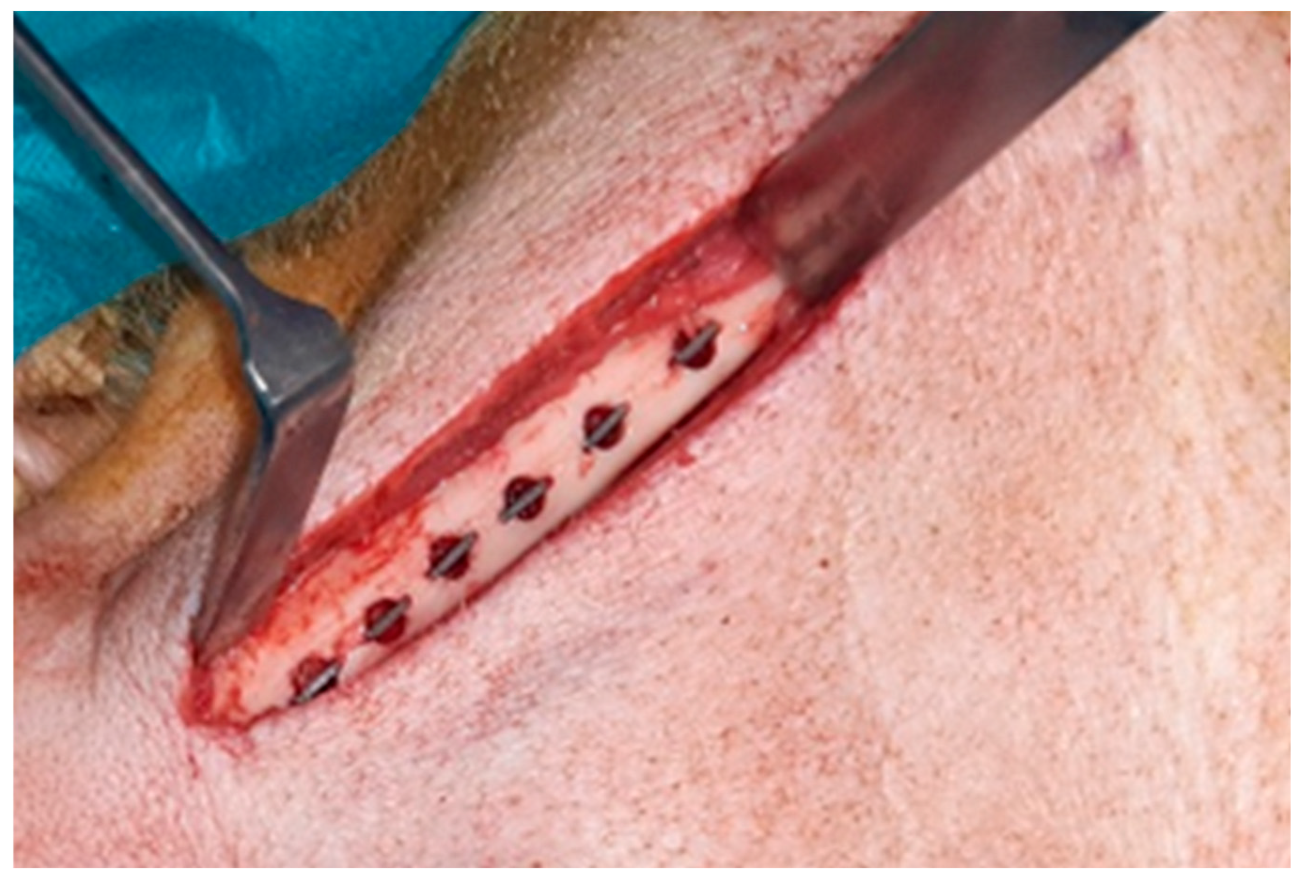
Figure 3.
A: DAPI stain of nuclei in periimplant tissue (blue); B: Overlay of DAPI stain and CD31 expression (red); C: Isolation of CD31 positive area; D: Digitization of CD31 positive area.
Figure 3.
A: DAPI stain of nuclei in periimplant tissue (blue); B: Overlay of DAPI stain and CD31 expression (red); C: Isolation of CD31 positive area; D: Digitization of CD31 positive area.
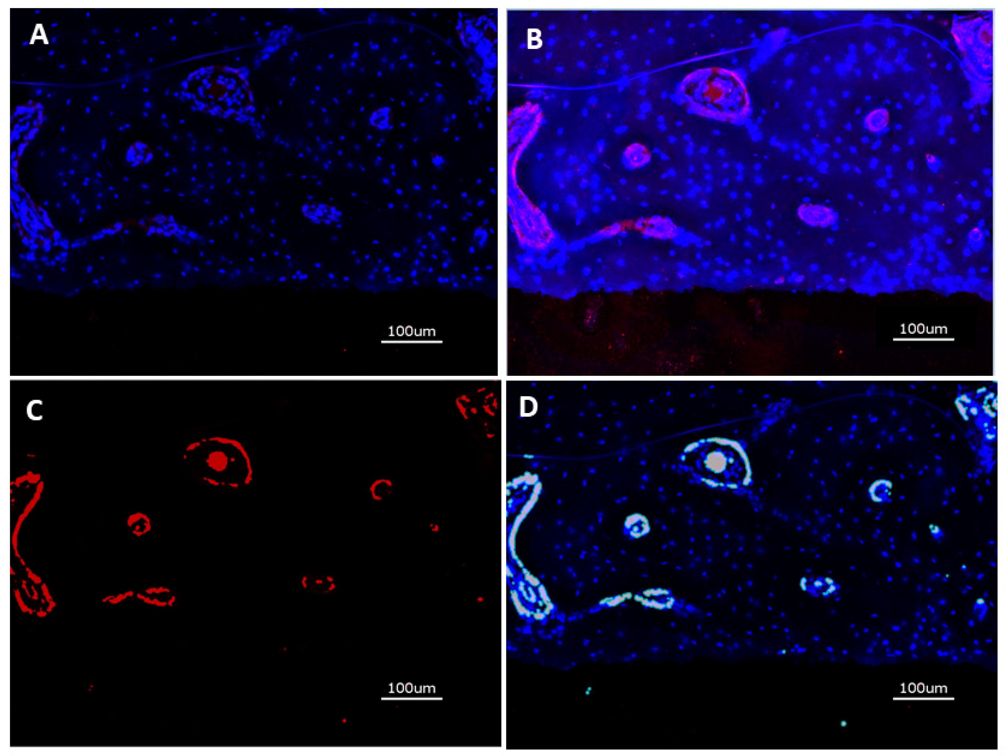
Figure 4.
Micrographs of periimplant bone formation: Top Row: 4 weeks, Bottom Row: 13 weeks, Bar: 2000 µm; A: (PLL-Hep)10 multilayer system loaded with rhBMP2 with a second (PLL-Hep)10 multilayer system loaded with rhVGEF165 on top; B: (PLL-Hep)10 multilayer system loaded with rhVGEF165 with a second (PLL-Hep)10multilayer system loaded with rhBMP2 on top; C: (PLL-Hep)20 multilayer system simultaneously loaded with rhVGEF165 and rhBMP2.; D: (PLL-Hep)20 multilayer system loaded with rhVGEF165 only; E: (PLL-Hep)20 multilayer system loaded with rhBMP2 only; F: (PLL-Hep)20 multilayer system without growth factor loading (control); G: Ti surface loaded simultaneously loaded with rhVGEF165 and rhBMP2; H: Ti surface loaded with rhVGEF165 only¸I: Ti surface loaded with rhBMP2 only; K: Ti surface unloaded (control).
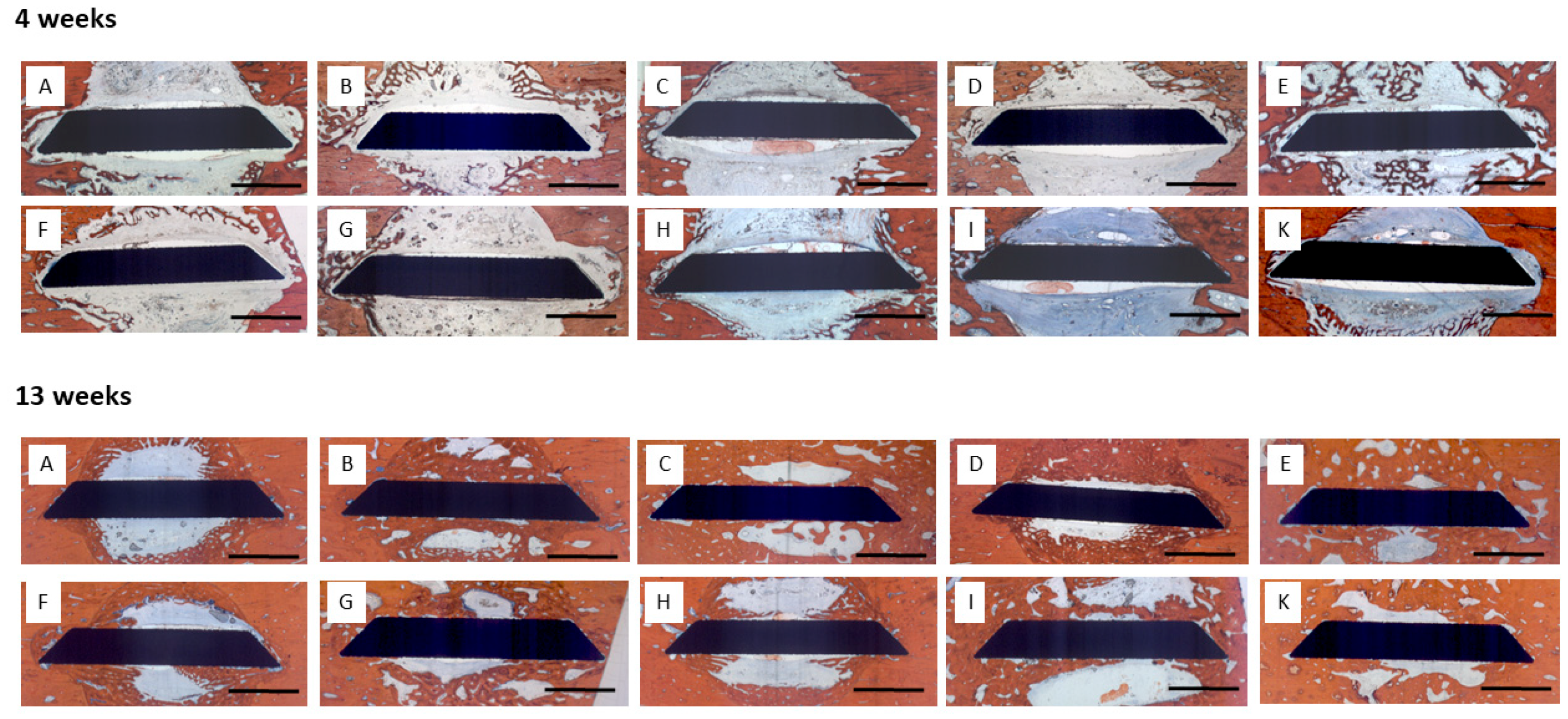
Figure 5.
Bone area (mm²) and bone density (%) of newly formed within the trephine defects. Data are presented as means ± standard deviation (SD) with n=6.
Figure 5.
Bone area (mm²) and bone density (%) of newly formed within the trephine defects. Data are presented as means ± standard deviation (SD) with n=6.
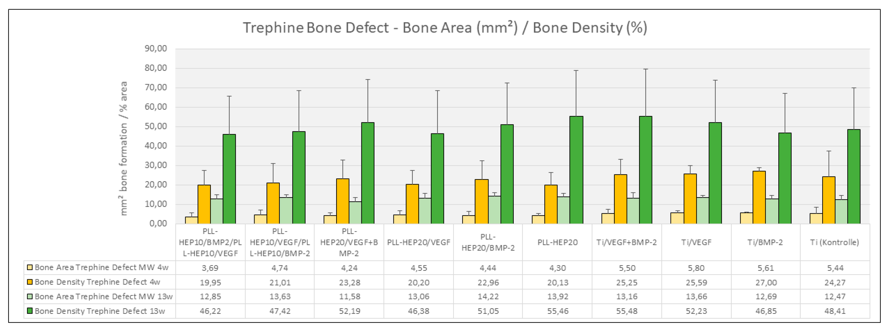
Figure 6.
Bone area (mm²) of newly formed within the periimplant zone (300 µm). Data are presented as means ± standard deviation (SD) with n=6.; *) :significantly different from Ti control surface (p=<0.05).
Figure 6.
Bone area (mm²) of newly formed within the periimplant zone (300 µm). Data are presented as means ± standard deviation (SD) with n=6.; *) :significantly different from Ti control surface (p=<0.05).
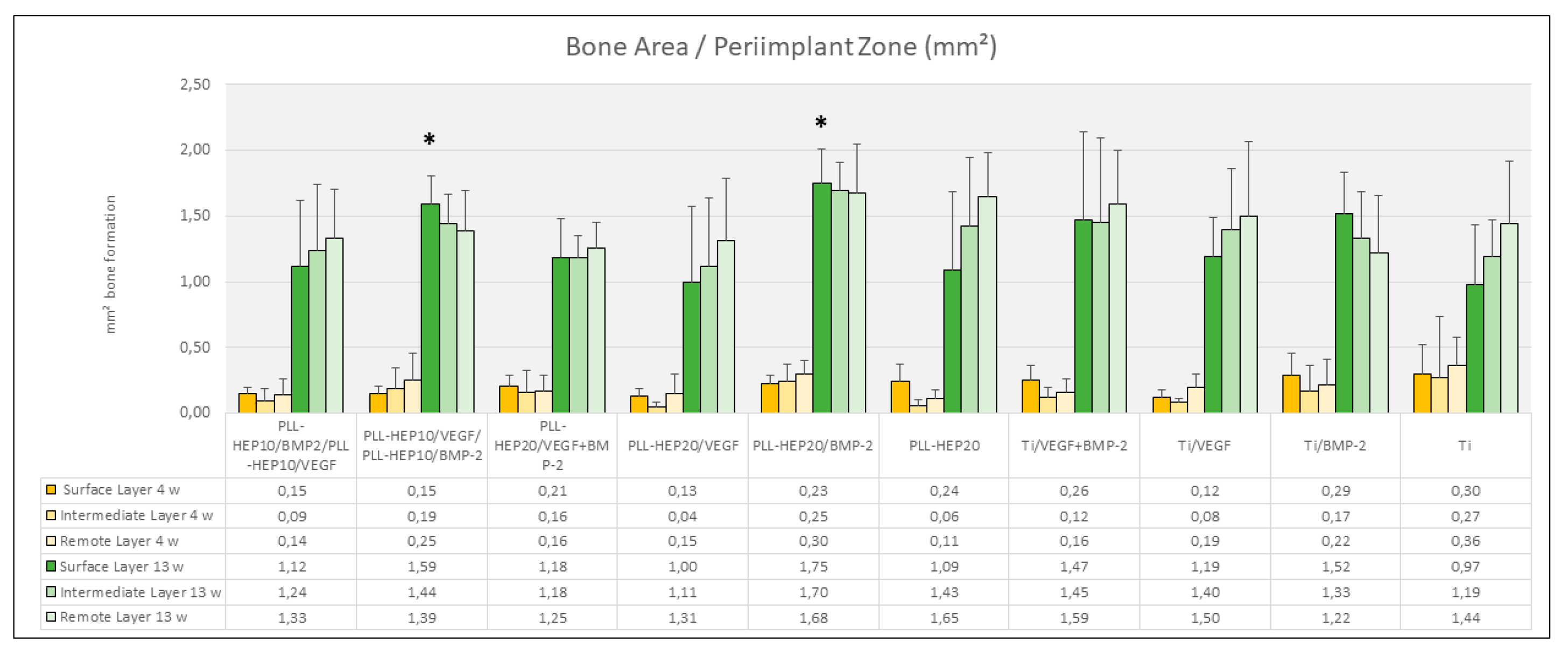
Figure 7.
Bone area (mm²) of newly formed within the immediate surface layer (100 µm). Data are presented as means ± standard deviation (SD) with n=6. *) :significantly different from Ti control surface (p=<0.05).
Figure 7.
Bone area (mm²) of newly formed within the immediate surface layer (100 µm). Data are presented as means ± standard deviation (SD) with n=6. *) :significantly different from Ti control surface (p=<0.05).
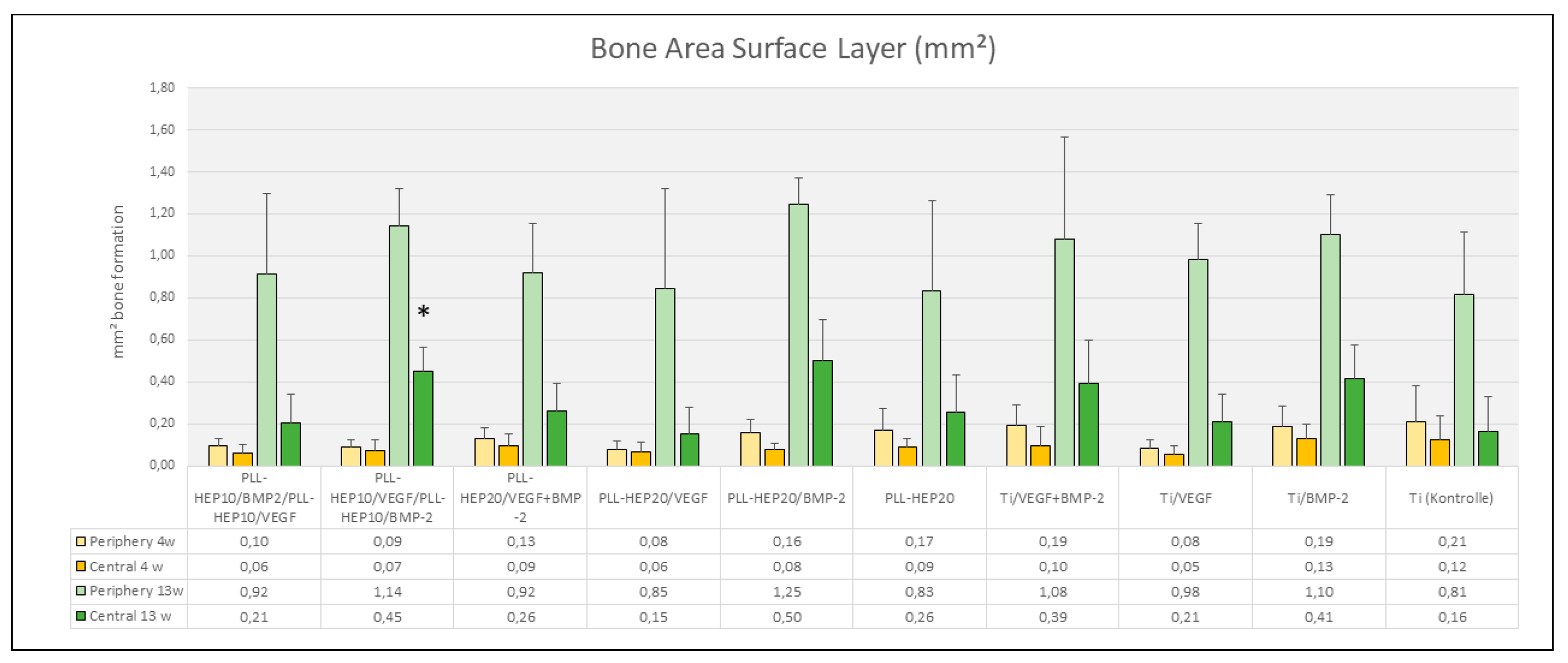
Figure 8.
Bone-Implant-Contact (%); Data are presented as means ± standard deviation (SD) with n=6; *): significantly different from Ti control surface (p=<0.05), §): significantly different from Ti surface loaded with BMP2 (p=<0.05).
Figure 8.
Bone-Implant-Contact (%); Data are presented as means ± standard deviation (SD) with n=6; *): significantly different from Ti control surface (p=<0.05), §): significantly different from Ti surface loaded with BMP2 (p=<0.05).
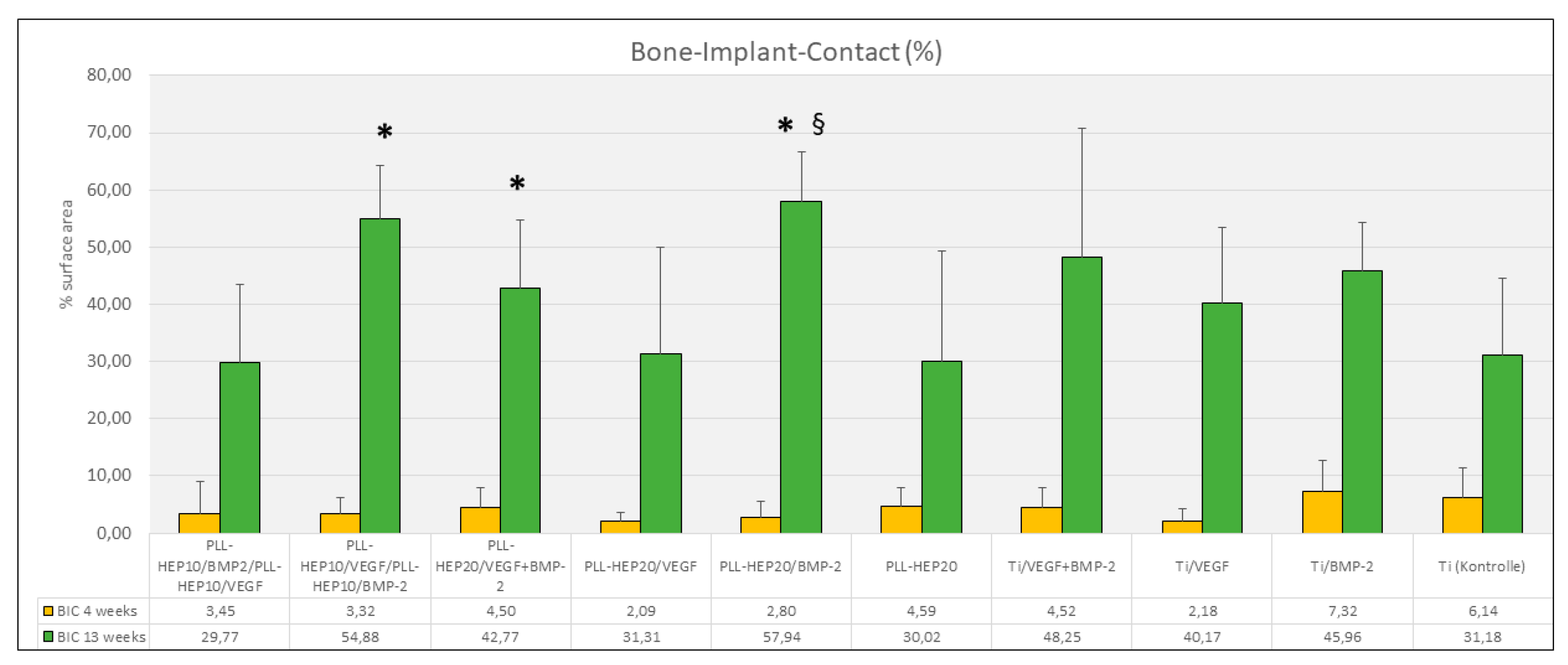
Figure 9.
Overview of CD31 positive expression after 4 weeks (bar = 100 µm); A: (PLL-Hep)10 multilayer system loaded with rhBMP2 with a second (PLL-Hep)10 multilayer system loaded with rhVGEF165 on top¸B: (PLL-Hep)10 multilayer system loaded with rhVGEF165 with a second (PLL-Hep)10multilayer system loaded with rhBMP2 on top; C: (PLL-Hep)20 multilayer system simultaneously loaded with rhVGEF165 and rhBMP2; D: Ti surface loaded simultaneously loaded with rhVGEF165 and rhBMP2; E: Ti surface loaded with rhBMP2 only; F: Ti surface unloaded (control).
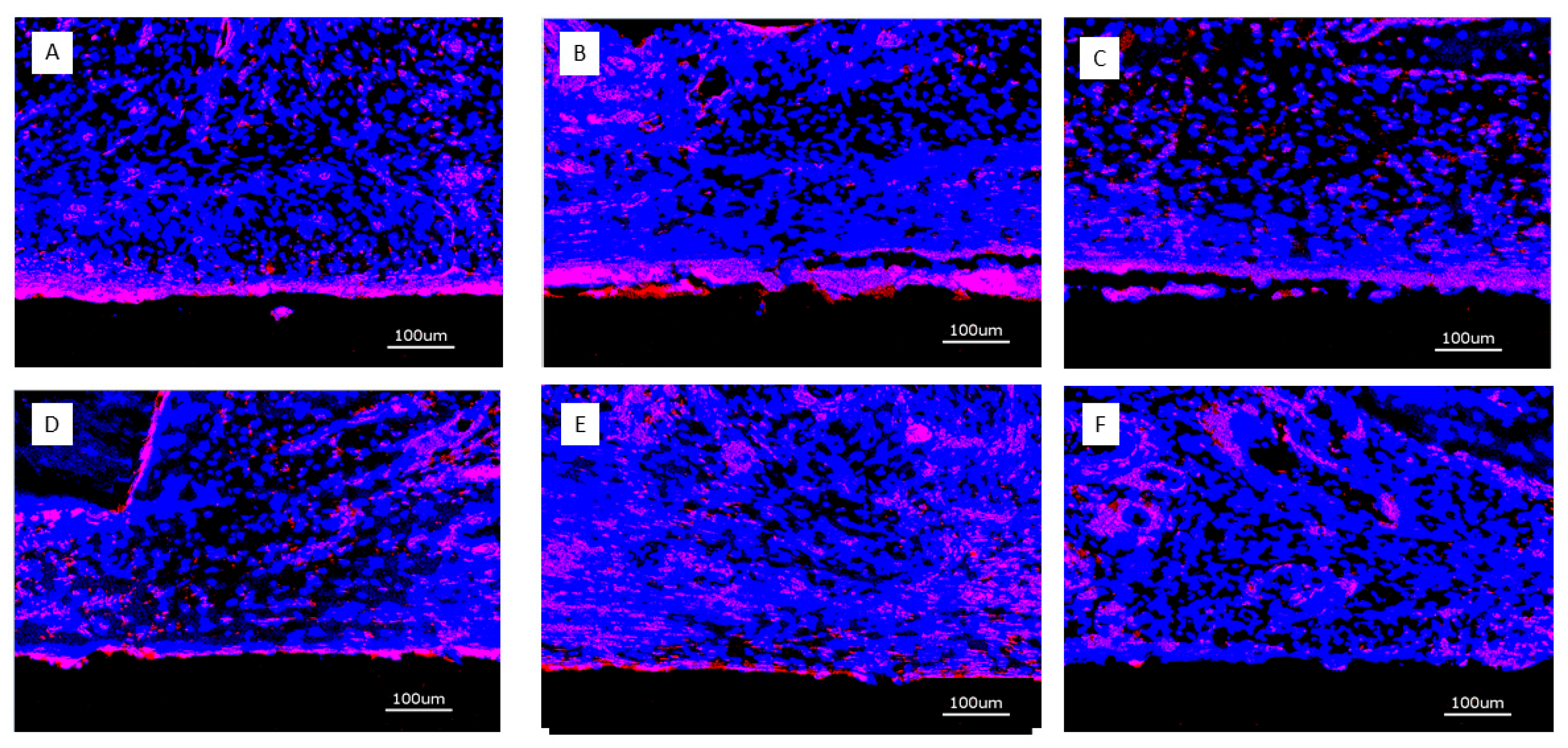
Figure 10.
Overview of CD31 positive expression after 13 weeks (bar = 100 µm); A: (PLL-Hep)10 multilayer system loaded with rhBMP2 with a second (PLL-Hep)10 multilayer system loaded with rhVGEF165 on top¸B: (PLL-Hep)10 multilayer system loaded with rhVGEF165 with a second (PLL-Hep)10multilayer system loaded with rhBMP2 on top; C: (PLL-Hep)20 multilayer system simultaneously loaded with rhVGEF165 and rhBMP2; D: Ti surface loaded simultaneously loaded with rhVGEF165 and rhBMP2; E: Ti surface loaded with rhBMP2 only; F: Ti surface unloaded (control).
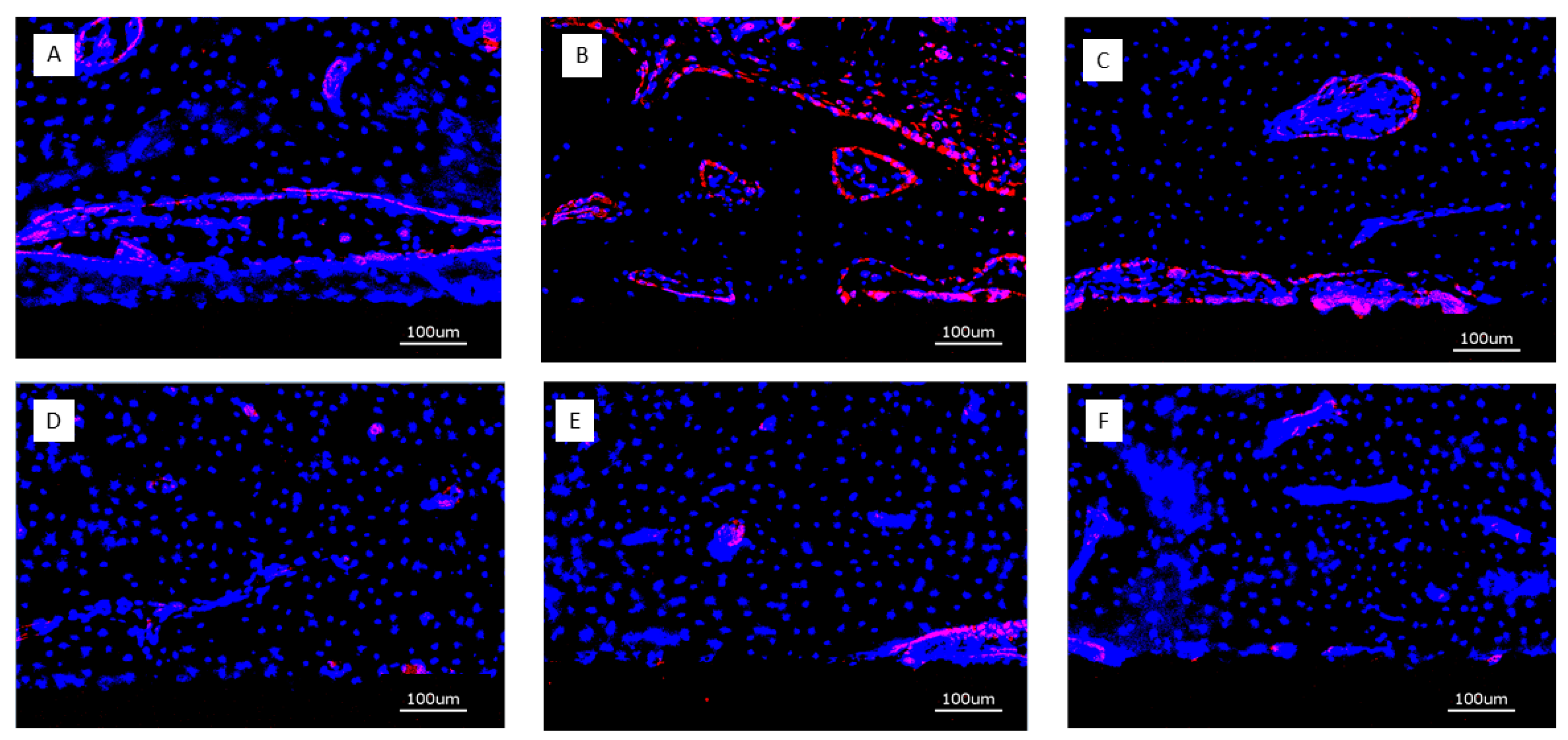
Figure 11.
Area of CD31 positive expression (µm² / 10³); Data are presented as means ± standard deviation (SD) with n=6.
Figure 11.
Area of CD31 positive expression (µm² / 10³); Data are presented as means ± standard deviation (SD) with n=6.
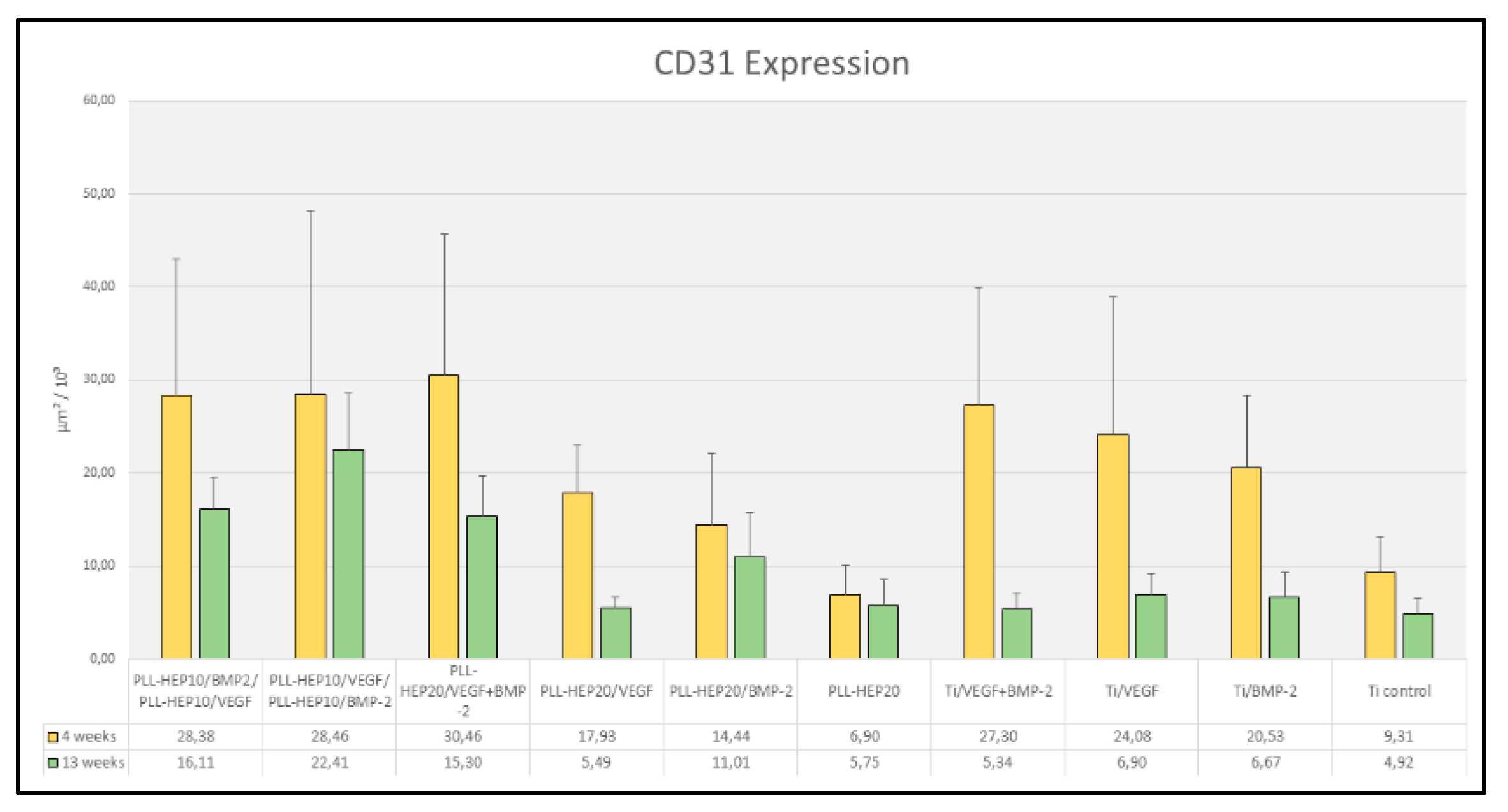

Table 1.
Experimental surface designs and growth factor loading (rhBMP2/rhVEGF165).
| rhBMP2 (µg/cm²) | rhVEGF165 (µg/cm²) | |||
| Mean | SD | Mean | SD | |
| PLL-HEP10/BMP-2&PLL-HEP10/VEGF | 3,8 | 1,3 | 5,5 | 0,4 |
| PLL-HEP10/VEGF&PLL-HEP10/BMP-2 | 5,9 | 0,6 | 5,0 | 0,7 |
| PLL-HEP20/VEGF+BMP-2 | 3,5 | 1,3 | 4,5 | 2,1 |
| PLL-HEP20/VEGF | 4,4 | 2,0 | ||
| PLL-HEP20/BMP-2 | 5,7 | 0,4 | ||
| PLL-HEP20 | ||||
| Ti/VEGF+BMP-2 | 2,9 | 1,8 | 4,6 | 0,4 |
| Ti/VEGF | 4,9 | 1,9 | ||
| Ti/BMP-2 | 3,1 | 2,2 | ||
| Ti Control | ||||
Table 2.
Growth factor release (rhBMP2/rhVEGF165) after 21 days.
| r hBMP2 (µg/cm²) | rhVEGF165 (µg/cm²) | |||
| Mean | SD | Mean | SD | |
| PLL-HEP10/BMP-2&PLL-HEP10/VEGF | 0,06 | 0,01 | 2,63 | 0,27 |
| PLL-HEP10/VEGF&PLL-HEP10/BMP-2 | 3,03 | 0,47 | 0,01 | 0,00 |
| PLL-HEP20/VEGF+BMP-2 | 1,96 | 0,28 | 1,49 | 0,29 |
| PLL-HEP20/VEGF | 1,70 | 0,28 | ||
| PLL-HEP20/BMP-2 | 2,59 | 0,43 | ||
| PLL-HEP20 | ||||
| Ti/VEGF+BMP-2 | 0,89 | 0,66 | 0,16 | 0,05 |
| Ti/VEGF | 0,27 | 0,02 | ||
| Ti/BMP-2 | 0,36 | 0,03 | ||
Table 3.
p-values of pairwise comparisons of CD31 expression after 4 weeks (Wilcoxon-tests).
| PLL-HEP10/BMP2 & PLL-HEP10/VEGF | PLL-HEP10/VEGF & PLL-HEP10/BMP-2 | PLL-HEP20/VEGF +BMP-2 | PLL-HEP20/ VEGF | PLL-HEP20/ BMP-2 | PLL-HEP20 | Ti/VEGF+ BMP-2 | Ti/VEGF | Ti/BMP-2 | Ti Control | |
| PLL-HEP10/BMP-2& PLL-HEP10/VEGF | ||||||||||
| PLL-HEP10/VEGF & PLL-HEP10/BMP-2 | 0.600 | |||||||||
| PLL-HEP20/VEGF +BMP-2 | 0.463 | 0.753 | ||||||||
| PLL-HEP20/VEGF | 0.043 | 0.345 | 0.043 | |||||||
| PLL-HEP20/BMP-2 | 0.028 | 0.075 | 0.028 | 0.225 | ||||||
| PLL-HEP20 | 0.028 | 0.028 | 0.028 | 0.043 | 0.075 | |||||
| Ti/VEGF+BMP-2 | 0.917 | 0.917 | 0.600 | |||||||
| Ti/VEGF | 0.753 | 0.753 | 0.686 | 0.686 | ||||||
| Ti/BMP-2 | 0.345 | 0.753 | 0.345 | 0.686 | 0.173 | |||||
| Ti Control | 0.028 | 0.028 | 0.028 |
Table 4.
p-values of pairwise comparisons of CD31 expression after 13 weeks (Wilcoxon-tests).
| PLL-HEP10/BMP2 & PLL-HEP10/VEGF | PLL-HEP10/VEGF & PLL-HEP10/BMP-2 | PLL-HEP20/VEGF +BMP-2 | PLL-HEP20/ VEGF | PLL-HEP20/ BMP-2 | PLL-HEP20 | Ti/VEGF+ BMP-2 | Ti/VEGF | Ti/BMP-2 | Ti Control | |
| PLL-HEP10/BMP-2& PLL-HEP10/VEGF | ||||||||||
| PLL-HEP10/VEGF & PLL-HEP10/BMP-2 | 0.028 | |||||||||
| PLL-HEP20/VEGF +BMP-2 | 0.249 | 0.028 | ||||||||
| PLL-HEP20/VEGF | 0.028 | 0.028 | 0.028 | |||||||
| PLL-HEP20/BMP-2 | 0.046 | 0.028 | 0.028 | 0.028 | ||||||
| PLL-HEP20 | 0.028 | 0.028 | 0.028 | 0.917 | 0.046 | |||||
| Ti/VEGF+BMP-2 | 0.028 | 0.028 | 0.028 | |||||||
| Ti/VEGF | 0.028 | 0.028 | 0.028 | 0.173 | ||||||
| Ti/BMP-2 | 0.028 | 0.028 | 0.028 | 0.917 | 0.028 | |||||
| Ti Control | 0.917 | 0.249 | 0.345 |
Disclaimer/Publisher’s Note: The statements, opinions and data contained in all publications are solely those of the individual author(s) and contributor(s) and not of MDPI and/or the editor(s). MDPI and/or the editor(s) disclaim responsibility for any injury to people or property resulting from any ideas, methods, instructions or products referred to in the content. |
© 2025 by the authors. Licensee MDPI, Basel, Switzerland. This article is an open access article distributed under the terms and conditions of the Creative Commons Attribution (CC BY) license (http://creativecommons.org/licenses/by/4.0/).
Copyright: This open access article is published under a Creative Commons CC BY 4.0 license, which permit the free download, distribution, and reuse, provided that the author and preprint are cited in any reuse.


