
Submitted:
03 January 2025
Posted:
06 January 2025
You are already at the latest version
Abstract
In complex underground parking scenarios, non-line-of-sight (NLOS) obstructions significantly impede positioning signals, presenting substantial challenges for accurate vehicle localization. While traditional positioning approaches primarily focus on mitigating NLOS effects to enhance accuracy, this research adopts an alternative perspective by leveraging NLOS propagation as valuable information, enabling precise positioning in NLOS-dominated environments. We introduce an innovative NLOS positioning framework based on the generalized source (GS) technique, which employs ray-tracing (RT) to transform NLOS paths into equivalent line-of-sight (LOS) paths. A novel GS filtering and weighting strategy to establish initial weights for the nonlinear equation system. To combat significant NLOS noise interference, a robust iterative reweighted least squares (W-IRLS) method synergizes initial weights with optimal position estimation. Integrating ultra-wideband (UWB) delay and angular measurements, four distinct localization modes based on W-IRLS are developed: angle-of-arrival (AOA), time-of-arrival (TOA), AOA/TOA hybrid, and AOA/time-difference-of-arrival (TDOA) hybrid. Comprehensive experimental and simulation results validate the exceptional effectiveness and robustness of the proposed NLOS positioning framework, demonstrating positioning accuracy up to 0.14 meters in specific scenarios. This research not only advances the state-of-the-art in NLOS positioning but also establishes a robust foundation for high-precision localization in challenging environments.
Keywords:
vehicle positioning
; time-of-arrival
; angle-of-arrival
; time-difference-of-arrival
; non-line-of-sight
; ray-tracing
1. Introduction
Accurate and reliable vehicle positioning has become a fundamental requirement in modern intelligent transportation systems (ITS) [1,2,3]. With the emergence of 5G/6G integrated sensing and communication systems (ISAC), precise positioning services have become key enablers for various applications, such as collision avoidance, cooperative driving, and intelligent navigation [4,5]. While significant progress has been made in vehicle positioning for open-road scenarios, underground parking environments pose unique challenges due to their confined spaces, severe signal attenuation [6,7], and limited access to satellite-based positioning systems like GPS [8,9,10].
In underground parking garages, accurate and continuous vehicle positioning is crucial for improving user experience, enhancing parking efficiency, and supporting safety-critical applications such as automated parking, vehicle retrieval systems, and efficient parking management [11,12,13]. As the development of autonomous driving and connected vehicles continues to accelerate, precise vehicle positioning in such environments not only improves the reliability of location-based services (LBS) but also minimizes potential risks caused by positioning errors, which could otherwise lead to inefficient parking operations or even accidents [14,15]. However, underground parking environments pose significant challenges for positioning technologies, including signal blockage, multipath effects, and non-line-of-sight (NLOS) propagation, which must be addressed to deliver precise and reliable location information [16]. Furthermore, the demand for seamless integration with intelligent navigation systems highlights the need for robust and scalable solutions tailored specifically to underground environments [17,18].
In recent years, researchers have proposed various solutions to address the problem of vehicle localization in non-line-of-sight (NLOS) scenarios. Vehicle localization technologies in obstructed environments are primarily based on platforms such as ultra-wideband (UWB), Wi-Fi, BLE, LiDAR, and visible light [19,20,21,22,23,24,25,26]. UWB is a short-range wireless communication technology that offers centimeter-level positioning accuracy and demonstrates excellent performance in complex multipath environments. Moreover, UWB technology employs low-power signal transmission, provides strong anti-interference capabilities, and is minimally impacted by electromagnetic interference from the environment, making it particularly suitable for NLOS localization applications [27,28,29].
NLOS localization techniques based on UWB generally focus on two main aspects: multipath mitigation techniques, represented by NLOS site identification [30,31,32,33] and NLOS error compensation [34,35,36], and multipath exploitation techniques based on geometric mapping [37,38,39,40,41,42]. Multipath mitigation techniques rely on empirical data to establish statistical characteristics of NLOS errors. Channel parameters such as RSS, root mean square (RMS) delay, and RMS angle are used to distinguish between line-of-sight (LOS) and NLOS sites [43,44]. In [45], researchers constructed a fingerprint database by combining UWB and Wi-Fi and utilized the Density Peak Clustering technique to differentiate LOS and NLOS sites, thereby improving localization accuracy. To better characterize the distribution of NLOS error features, some scholars have adopted machine learning techniques [46,47,48]. For instance, in [49], researchers applied the long short-term memory (LSTM) method to train and identify raw channel impulse response (CIR) data collected from UWB channels, enhancing the accuracy of time-of-arrival (TOA) algorithms in NLOS scenarios. In [50], convolutional neural networks (CNNs) and LSTM techniques were simultaneously applied for NLOS site identification, achieving an identification accuracy of over 82%.
While deep learning methods have shown promising performance in NLOS environments, their reliance on large amounts of labeled data and high computational complexity remain significant challenges for practical applications. As a classical state estimation method, the Kalman Filter (KF) has emerged as a vital tool for addressing NLOS localization problems due to its real-time performance and robustness in dynamic systems [51,52,53]. In [54], researchers proposed a robust extended Kalman filter (REKF) algorithm combined with distance constraint, which improved localization accuracy in NLOS scenarios. The work in [55] introduced a novel localization strategy based on constrained square root unscented Kalman filtering (CSRUKF) and the robust Taylor series (RTS) algorithm, further enhancing the robustness of NLOS error mitigation.
Although the aforementioned traditional localization methods have demonstrated significant effectiveness in improving vehicle localization accuracy in NLOS scenarios, their heavy reliance on empirical data often leads to high costs in data acquisition and model training. To overcome this limitation, researchers have shifted their focus to exploiting multipath information in complex environments for localization. In [56], scholars utilized the single-reflection mechanism of scatterers to identify virtual sources (VSs) and incorporated a two-step least squares (TSWLS) method to enhance localization accuracy in NLOS scenarios. The work in [57] expanded the concept of VSs to include multiple scattering propagations, combining angle-of-arrival (AOA) and TOA hybrid localization methods to improve the applicability and robustness of VS techniques in NLOS scenarios. To further enhance algorithm accuracy and efficiency, in [58], researchers applied VS techniques to hybrid AOA and time-difference-of-arrival (TDOA) localization and proposed an initial position estimation method. This approach, combined with the TSWLS technique, achieved effective localization under NLOS conditions.
The VS technique has demonstrated remarkable localization performance in NLOS scenarios; however, it still faces several significant limitations. Many existing methods do not fully exploit the complete information provided by channel propagation and lack a thorough analysis from the perspective of electromagnetic wave behavior. While TOA-based cooperative localization algorithms can precisely determine the positions of virtual sources for each multipath, non-cooperative methods such as AOA or TDOA struggle to achieve comparable accuracy. This shortcoming greatly diminishes their performance in complex multipath environments, making it challenging to meet the requirements of high-precision localization. In addition, most approaches rely on a single localization algorithm, which proves inadequate for scenarios like underground parking garages with complex reflections and diffractions. These environments, characterized by prominent multipath effects and highly intricate propagation paths [59], pose substantial challenges to the VS technique. Furthermore, the influence of modeling accuracy on algorithm performance is often neglected, further limiting the effectiveness of these methods in complex scenarios.
To address the aforementioned issues, this paper proposes an NLOS vehicle localization-based service framework that utilizes state-of-the-art ray-tracing (RT) [60] and the generalized source (GS) technique. In the proposed method, an innovative GS filtering method based on geometric restriction conditions (GRC) and a GS weighting method utilizing physical channel characteristics are introduced to improve the algorithm’s accuracy and applicability in NLOS propagation environments. Additionally, a robust IRLS method with initial weights (W-IRLS) is proposed to solve equations containing NLOS noise. Meanwhile, the RT-VLBS platform, based on a UWB system, supports TOA and AOA/TOA cooperative localization modes, as well as AOA and AOA/TDOA non-cooperative localization modes. The contributions of this paper can be summarized as follows:
- We propose an innovative ray-tracing vehicle localization-based service (RT-VLBS) framework that leverages multipath assistance through the integration of the GS technique and RT methodology. The framework effectively converts NLOS paths into valuable positioning information, achieving robust and high-precision localization in NLOS environments.
- A novel GS filtering and weighting strategy is proposed to heuristically optimize the weights of NLOS nonlinear localization equations, substantially improving both the accuracy and reliability of the positioning algorithm.
- Extensive experiments using the UWB system in an underground parking garage, strategically designed to capture NLOS multipath propagation characteristics, comprehensively validated the effectiveness and reliability of RT-VLBS in challenging NLOS scenarios.
- To verify the RT-VLBS’s robustness and reliability, different measurement parameter errors and environmental geometric modeling errors in NLOS scenarios were simulated and analyzed.
The rest of this paper is organized as follows: Section 2 outlines the fundamental principles of GS under the assistance of RT, including GS generation, filtering, and weight calculation. Section 3 introduces the localization methods utilized by the RT-VLBS platform, encompassing four localization modes: AOA, TOA, joint AOA/TOA, and joint AOA/TDOA, along with the application of the W-IRLS method in each mode. Section 4 details the experimental validation conducted in an underground parking garage under NLOS conditions, using a platform equipped with UWB technology to demonstrate the effectiveness of the RT-VLBS. Section 5 presents extensive simulation experiments to assess the robustness of the RT-VLBS platform under varying measurement errors and environmental geometric modeling uncertainties. Finally, the findings of this study are discussed, along with its limitations.
2. Basic Principles of RT-Assisted Generalized Sources
2.1. GS Generation
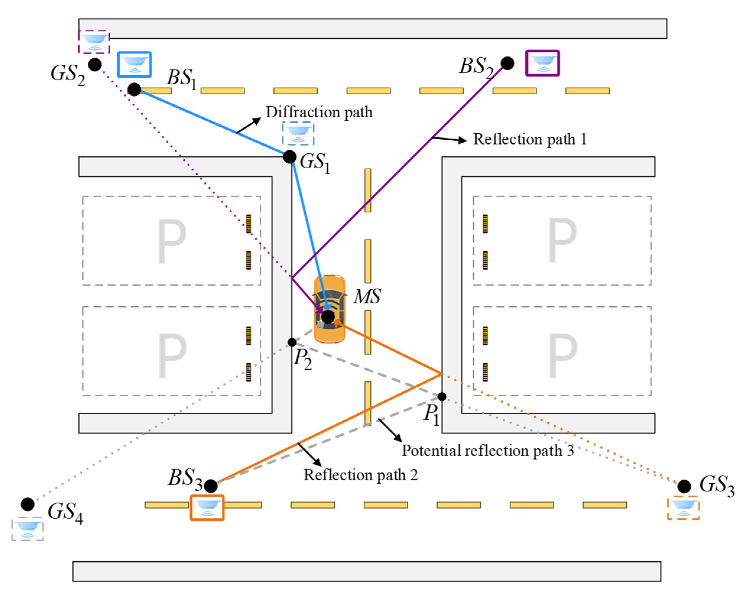
In the NLOS environment of an underground parking garage, electromagnetic waves between the mobile station (MS) and base stations (BSs) are typically blocked by obstacles, resulting in NLOS conditions in most scenarios. As illustrated in Figure 2, , , and represent three base stations, while is a mobile station placed on a sedan. In this scenario, the MS is in an NLOS state with respect to the BSs. The RT algorithm is employed to convert NLOS paths into LOS paths. In the scenario depicted in Figure 2, with the RT search depth set to 1, the GS of , , and are derived as , , and . Among them, is a diffraction GS, while and are reflection GSs. By adjusting the search depth, GSs at different multipath depths can be obtained.
2.2. GS Filtering
The proliferation of GSs is fundamentally determined by two key factors: environmental complexity and the depth of RT algorithm exploration. In complex scenarios such as underground parking garages, the multipath propagation between MS and BS frequently extends to first-order or higher, resulting in the generation of numerous GSs associated with each BS. While TOA-based localization modes can effectively filter out superfluous GSs through precise delay information, AOA-based and TDOA-based approaches face significant challenges due to the absence of reliable prior information for determining valid multipath propagation depths between MS and BS. This limitation leads to the persistence of numerous invalid GSs in the system. The resultant NLOS-induced noise can severely impact the localization performance, either by disrupting the convergence of localization equations or, in more severe instances, causing substantial deviations from the actual target position.
We propose an innovative filtering approach based on generalized source pairs (GSPs), formed by systematically pairing individual GSs. By leveraging the observation parameters of each GS, we construct an initial set of localization equations, comprising AOA, TOA, and TDOA equations. Notably, while AOA and TOA equations directly utilize parameters from the GSPs, TDOA equations require supplementary reference GSs beyond the paired structure.
Consider a GSP containing and with coordinates and , respectively. The multipath information for is characterized by , while for it is denoted as , where represents the angle of arrival, indicates the propagation delay, and denotes the delay difference. Given that the target position to be determined within the GSP is , localization equations can be constructed based on the multipath information of the GSP:
Among these formulations, Equation (1) represents the AOA-based localization equations, Equation (2) describes the TOA-based localization equations, and Equation (3) characterizes the TDOA-based localization equations. In these equations, designates the coordinates of the reference GS within the GSP framework.
To optimize localization accuracy, we introduce a comprehensive framework that synergistically combines different localization parameters. The proposed system implements four distinct solution modes, each utilizing specific observation parameters: a standalone AOA-based mode, a standalone TOA-based mode, and two hybrid modes - AOA/TOA and AOA/TDOA. For each GSP, an initial solution is computed using the least squares (LS) methodology.
The algorithm implements two geometric restriction conditions (GRCs) to validate the GSP selections. The first GRC enforces that the GSP solution must be contained within a predefined feasible domain. The second GRC examines the geometric integrity of multipath reflection points, ensuring they do not intersect with environmental obstacles. For instance, as depicted in Figure 2, generates a second-order reflection path that produces two GSs, and , with corresponding reflection points and . The geometric validity of any GSP containing or is determined by examining the line segments and ; the presence of any obstacles along these segments renders the corresponding GSP geometrically invalid.
| Algorithm 1. GS Filtering algorithm |
| Precondition: Generate all GS, with the total number denoted as N. |
| Pairing the GSs to construct GSPs. |
| Foreach GSP in GSPs |
| Formulate base Equations (1)-(3) and compute the initial solution of the GSP through LS optimization. |
| If x exists and satisfies GRCs |
| Increment the weight count of the and in the current GSP by 1. |
| End If |
| End Foreach |
| Filter out GSs with zero weight count |
| Proceed to subsequent processing steps |
Algorithm 1 delineates the systematic procedure for GS filtering. The process initiates with solving localization equations for each formed GSP. When a solution exists and satisfies the GRCs, the algorithm increments the weight counter of both constituent GSs within that GSP by 1. Following the comprehensive evaluation of all GSPs, the algorithm eliminates GSs with zero weight counts from further consideration.
2.3. GS Weighting
While the initial filtering process eliminates certain erroneous GSs, the environmental complexity introduces additional challenges, potentially retaining a substantial number of invalid GSs in the valid set. Figure 2 illustrates this phenomenon through and , which are mutually exclusive under physical propagation conditions: is valid for a first-order reflection path between and , whereas corresponds to a valid second-order reflection path. This ambiguity compounds with increasing search depth, leading to a proliferation of such invalid GSs.
To overcome this challenge, we propose a residual-based GS weighting methodology. As depicted in Figure 1, the approach initially employs hierarchical clustering to consolidate the preliminary GSP solutions into GSP clusters (GSPCs). Subsequently, RT techniques are employed to compute cluster central multipath information between the target position and BSs, which can be formulated as:
where denotes the angle of arrival, is the time of arrival, represents the time difference of arrival, signifies the received signal strength (RSS), and indicates the RSS differential.
Figure 1.
Flowchart of RT-VLBS algorithm. The algorithm consists of three main components: (1) GS generation based on ray-tracing and environmental data, (2) GS filtering through geometry restriction rules, and (3) GS weighted localization incorporating robust solver and weight matrix.
Figure 1.
Flowchart of RT-VLBS algorithm. The algorithm consists of three main components: (1) GS generation based on ray-tracing and environmental data, (2) GS filtering through geometry restriction rules, and (3) GS weighted localization incorporating robust solver and weight matrix.
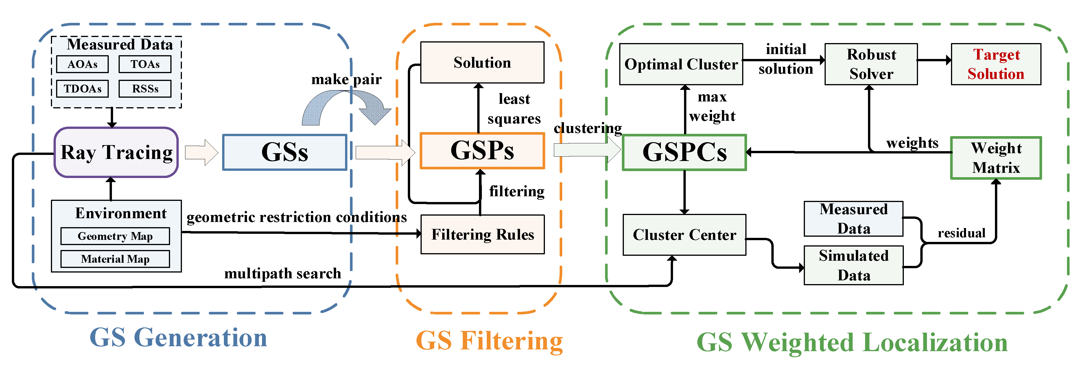
Figure 2.
Vehicle localization based on GSs from multipath propagation in an underground parking scenario. The figure illustrates the diffraction path and multiple reflection paths between base stations (BSs) and mobile stations (MS), with corresponding GSs generated from different propagation mechanisms.
The normalized residual between the and the actual measured multipath information differs depending on the measurement parameter. This paper provides the normalized residual expressions for the four cases: AOA, TOA, AOA/TOA hybrid, and AOA/TDOA hybrid:
Here, , , and represent the weight coefficients for angular, delay, and power residual components respectively. Weight sum constraints ( for AOA, for TOA, for hybrid cases) must be satisfied. Though typically assigned equal values, these weights can be dynamically adjusted based on measurement error variations.
The normalized weight expression for a GSPC is given as:
Following the computation of GSPC weights, the algorithm updates the weights of individual GSs within each cluster. The aggregation of all GS weights yields an initial weight matrix , structured as a diagonal matrix , where denotes the total number of GSs.
3. Vehicle Localization Algorithm
3.1. Initial Solution Selection
Under NLOS conditions, the positioning equation solution exhibits high sensitivity to initial value selection, where an appropriate initial value is crucial for ensuring rapid convergence. The proposed algorithm designates the highest-weighted solution within the GSPC as the initial solution, expressed as .
The positioning accuracy in AOA/TDOA hybrid scenarios is heavily dependent on the selection of the reference GS. A key challenge stems from the uncertainty of the specific multipath propagation between the reference BS and MS, which prevents the determination of the corresponding reference GS. This paper presents a heuristic approach to resolve this issue. The method employs RT algorithms to analyze multipath propagation between the initial solution of the highest-weighted GSPC and reference BS, subsequently selecting the GS associated with the minimum-delay multipath as the best reference GS.
3.2. Robust Localization Estimator
Various positioning equations can be formulated according to different observation parameters. Converting Equations (1–3) into their corresponding error forms yields:
In the IRLS method, linearization of the objective function is crucial for iterative position updating. At the -th iteration, the initial position (obtained from the optimal cluster center in the first iteration ) serves as the linearization point. The error functions , , and are approximated through first-order Taylor series expansion, neglecting higher-order terms, resulting in:
The gradient expressions , , and are derived from equations (13-15):
For each set of AOA, TOA, and TDOA measurements, the linear equations can be rearranged into the following form:
Here, , represents the gradient matrix, and denotes the residual term of the equation. By rearranging Equation (19), the matrix form can be written as:
where represents the Jacob matrix, and denotes the residual error vector. The expression of under the four positioning modes is given as:
Large residuals in the positioning equations, resulting from NLOS noise, adversely affect solution accuracy. NLOS noise can be effectively suppressed through robust loss functions that respond to residual magnitudes. Denoting the robust loss function as with its first derivative, the iterative weight update can be expressed as:
The representative robust loss functions commonly employed include Huber loss, Cauchy loss, Tukey loss, and Geman-McClure loss:
The damping parameter for each iteration is defined as the standard deviation of all residuals. This threshold effectively reduces the weights of GSs exhibiting large residual deviations, thereby accelerating convergence and enhancing positioning efficiency. The IRLS method implementation employs two termination criteria: a maximum iteration count of 30 and a position increment threshold of .
Thus, the total weight matrix at each iteration is given by:
Specifically, the update for each weight element is:
With the weight matrix introduced, the position increment is derived via the IRLS formulation as:
The position estimate for the -th iteration is calculated as:
4. Experimental Results in Underground Parking Garage
4.1. Measurement Equipment
A dual-channel UWB direction-finding system was deployed for this measurement campaign as illustrated in Figure 3. The system integrated a DMW1000 chip for UWB signal measurements with an NXP SR150 MCU, which processed the dual-channel UWB data and computed AOA estimates [61]. The data was transmitted to a local host through a UART interface. Performance testing demonstrated the UWB device achieved measurement accuracies of 0.1 m for time delay and 8° for angle determination.
4.2. Measurement Scenario
The experiments were conducted in a relatively open underground parking garage. A handheld laser LiDAR system, with 5 cm modeling accuracy, was employed to capture the scene’s geometric structure. Figure 4 displays the raw point cloud data of the garage, revealing multiple wall structures and isolated rooms that create numerous NLOS conditions. Figure 5 shows the geometric model extracted from the point cloud, encompassing a 50 m × 50 m area. The test environment features two major room obstructions and several load-bearing columns.
Figure 6 shows the point cloud collection device, which incorporates an IMU module for precise position measurement. The device’s integrated SLAM module provided accurate position determination, eliminating reference frame discrepancy errors. The UWB tag was mounted on top of the point cloud device.
The measurement setup comprised four UWB anchors and one UWB tag. The anchors were strategically mounted on walls throughout the scene shown in Figure 7, at a consistent height of 1.85m above the ground, at coordinates , ,, and . Portable power banks supplied power to each anchor. To establish accurate reference path coordinates for evaluation, UWB parameter collection was conducted simultaneously with point cloud scanning.
4.3. Localization Accuracy Validation
This section analyzes the UWB device data and validates the positioning algorithm’s accuracy. The measurement trajectory shown in Figure 7 was completed in approximately 160 seconds at a constant speed of 1.5 m/s. Figure 8 depicts the UWB channel propagation distances over time, showing time delay variations due to multipath effects, which are particularly significant under NLOS conditions. Figure 9 and Figure 10 present the UWB-measured angle and power data, respectively.
Five position estimators were compared to validate the algorithm’s accuracy, all utilizing the GS technique:
(1) W-IRLS (proposed algorithm): Incorporates the initial weighted matrix and uses the optimal GSPC as the initial solution.
(2) IRLS: Uses the optimal GSPC as the initial solution but assigns equal weights to all equations.
(3) TSWLS: Implements the classical two-step weighted least squares approach, using only the LS method for the initial solution without initial weights.
(4) WLS: Employs both the weighted matrix and the optimal GSPC as the initial solution.
(5) LS: Directly solves equations using the least squares approach, without weights or initial solution.
The evaluation framework encompasses four positioning methods based on UWB device measurements: AOA-based positioning, TOA-based positioning, hybrid AOA-TOA positioning, and hybrid AOA-TDOA positioning.
Figure 11, Figure 12 , Figure 13 and Figure 14 illustrate the comparison of these methods’ positioning results with the actual trajectory. Figure 15, Figure 16, Figure 17 and Figure 18 display the cumulative distribution functions (CDFs) for each positioning algorithm. The positioning errors of different algorithms were analyzed across four positioning modes: AOA, TOA, AOA/TOA, and AOA/TDOA. The average location error (ALE) and standard deviations (STD) for each mode are summarized in Table 1 and Table 2, respectively. While all five algorithms exhibit suboptimal performance in the AOA positioning mode due to significant measurement errors, the proposed W-IRLS method demonstrates superior performance with an accuracy of 2.17m. The W-IRLS method continues to outperform in other positioning modes, achieving average accuracies of 0.18m in TOA mode, 0.14m in AOA/TOA mode, and 0.3m in AOA/TDOA mode. The consistently superior performance of the W-IRLS method across all positioning modes underscores the effectiveness of our proposed weighted matrix and optimal initialization based on the GS technique.
5. Robust Analysis of RT-VLBS Framework
The GS technique achieves high positioning accuracy in NLOS scenarios, but its performance depends on measurement precision and geometric modeling accuracy. While UWB platforms provide high-precision time delay measurements, extreme conditions can increase measurement errors, challenging algorithm noise robustness. In terms of geometric modeling, point cloud modeling offers high precision but limited practical applicability, while common maps like Planet and OpenStreetMap have decimeter-to-meter-level accuracy, impacting GS positioning algorithms. This section examines how measurement errors and geometric modeling precision affect positioning algorithm performance.
5.1. Simulation Environment
Figure 19 depicts a 50m × 50m NLOS scenario with smooth-plane reflector surfaces. Anchor and tag positions were selected to test diverse propagation conditions. Three anchors were positioned at , , and , while tags were placed at three locations: , , and . Position provides LOS conditions between the tag and all anchors. At position , only maintains LOS with the tag, while other anchor paths involve single reflections or diffractions. Position represents complete NLOS conditions, where UWB signals reach anchors through multiple reflections and diffractions.
5.2. Comparison of Localization Accuracy with Different AOA Errors
The accuracy and robustness of the proposed W-IRLS algorithm based on the GS technique were evaluated through two simulation rounds. The first round assessed positioning accuracy under varying error conditions. In the first simulations, TOA error followed a Gaussian distribution with 3 ns STD, while RSS error was modeled as Gaussian with 6 dB STD, reflecting typical RT model accuracy. AOA error was simulated as a Gaussian random variable with an STD ranging from 0.1° to 8°. Root mean square error (RMSE) calculations were based on 10,000 independent simulation runs.
Figure 20, Figure 21 and Figure 22 demonstrate the W-IRLS algorithm’s positioning accuracy under varying angular error conditions. While increasing AOA errors leads to higher positioning errors in AOA-based algorithms, methods incorporating time-based parameters (TOA and TDOA) achieve notably superior accuracy with sub-meter-level precision. Table 3 and Table 4 show the statistics of ALEs of different methods. The positioning method incorporating the GS technique proves both accurate and robust in LOS and NLOS conditions.
5.3. Comparison of Localization Accuracy Under Different Map Errors
The second simulation round examined positioning accuracy under varying map errors, with RMSE calculated from 10,000 independent runs. The simulation used zero-mean Gaussian distributions for TOA (3 ns STD), AOA (2° STD), and RSS (6 dB STD) errors. Figure 23 shows the geometric building corner point p error, modeled as a zero-mean Gaussian distribution with a STD ranging from 0.01 m to 2.0 m. Corner position displacement affects wall tilt angles, altering GS locations and consequently introducing positioning system errors.
Figure 24 illustrates positioning errors for the tag at point across different modes. Environmental displacement shows minimal impact on all four algorithms’ accuracy. This stability stems from point ’s LOS conditions with all three anchors, where the absence of reflection or diffraction paths renders the positioning independent of environmental modeling errors.
Figure 25 shows positioning errors for the tag at point B across different modes. Algorithm accuracy degrades with increasing environmental displacement. While the tag maintains LOS conditions with , its reflection paths to and are dependent on environmental modeling accuracy, thus affecting overall positioning performance.
Figure 26 demonstrates positioning errors for the tag at point across different modes. The positioning accuracy shows the highest sensitivity to environmental modeling errors, as all paths between the tag and anchors are NLOS. This increased sensitivity is reflected in the error curve’s steeper slope compared to point ’s results.
Table 5 summarizes the errors caused by average geometric modeling accuracy for four different positioning modes. From the perspective of the tag’s position, the complexity of the channel between the tag and the anchors (e.g., the number of multipath bounces) directly affects the accuracy of the positioning algorithms. In other words, the more complex the multipath, the greater the error caused by geometric modeling inaccuracies.
Analysis of the four positioning modes reveals distinct performance characteristics: The AOA/TOA algorithm demonstrates superior robustness, achieving a positioning error of 0.83 m per unit of geometric modeling accuracy in fully NLOS scenarios. Following closely, the TOA algorithm exhibits strong performance with a 0.98 m error per unit. The AOA/TDOA algorithm ranks third with a 1.67 m error per unit, while the AOA/TDOA positioning algorithm shows the highest environmental sensitivity, resulting in a 2.0 m error per unit of geometric modeling accuracy.
6. Discussion and Future Work
Extensive experiments and simulations conducted in underground parking garages demonstrate that the proposed RT-VLBS platform performs exceptionally well in NLOS scenarios. However, we outline two limitations of the proposed algorithm and identify key issues to address in future work:
(1) Dynamic Environments: The proposed algorithm was validated in a completely static underground parking garage. It does not account for the dynamic characteristics of parking garages, such as the presence of pedestrians and vehicles, which can introduce additional power attenuation and delay to UWB signals. Future work should evaluate the impact of dynamic factors (e.g., pedestrians and vehicles) on the positioning performance of RT-VLBS. Statistical analysis methods should be employed to establish relationships between dynamic features and UWB signal propagation characteristics, improving the adaptability of the RT-VLBS method.
(2) 2.5D Limitations: The proposed RT-VLBS method operates in a 2.5D framework. However, in scenarios with sloped surfaces or spiral ramps, as commonly found in underground parking garages, more complex 3D structural features must be taken into account. Future work should focus on developing a fully 3D RT-VLBS method to enhance positioning accuracy in these challenging environments.
Furthermore, we suggest the following areas as key focal points for future research:
(1) Anchor Placement Optimization: Traditional anchor placement is typically assessed based on the geometric dilution of precision (GDOP) in LOS scenarios. However, RT-VLBS leverages multipath signals for positioning. Therefore, future research should explore anchor placement strategies that consider the GDOP in the context of the RT-VLBS method, optimizing placement to improve positioning accuracy.
(2) Integration with Intelligent Reflecting Surfaces: The emergence of intelligent reflecting surfaces (IRS) offers the potential to alter the propagation direction of electromagnetic waves, introducing new channel information. In the planning of future smart parking garages, integrating the RT-VLBS method with IRS could significantly enhance positioning performance.
These proposed directions aim to address the identified limitations and further improve the RT-VLBS platform’s robustness and applicability in practical scenarios.
7. Conclusion
This paper proposes an innovative UWB positioning framework for NLOS scenarios based on the GS technique. In complex NLOS environments, the RT algorithm converts NLOS paths into equivalent LOS paths. A state-of-the-art GS filtering and weighting method is designed to determine the initial weights for solving nonlinear equations. Furthermore, we propose a robust W-IRLS method that effectively mitigates the adverse effects of complex NLOS noise environments, substantially improving the positioning algorithm’s resilience and reliability. The framework comprehensively evaluates four distinct positioning modes: AOA, TOA, hybrid AOA/TOA, and integrated AOA/TDOA. Comprehensive experimental validation and simulation studies demonstrate the superior performance of our proposed NLOS positioning algorithm, achieving an exceptional positioning accuracy of 0.14 meters in challenging NLOS environments. This breakthrough research establishes a robust theoretical and practical foundation for next-generation high-precision NLOS positioning services, facilitating seamless integration of communication and sensing technologies.
Author Contributions
Conceptualization, S.H., L.G., and Z.L.; methodology, S.H.; software, S.H.; validation, S.H., S.G., and Z.L.; formal analysis, Z.L.; investigation, S.H.; data curation, S.H., and S.G.; writing original draft preparation, S.H.; writing—review and editing, S.H.; visualization, S.H.; project administration, L.G., and Z.L.; funding acquisition, L.G., and Z.L. All authors have read and agreed to the published version of the manuscript.
Funding
This work was supported in part by the key project of Social Governance and Scientific and Technological Support for Smart Society (Grant No. 2022YFC3301403), the Key Basic Research Project of the Foundation Strengthening Program, the Foundation of China Information Technology Designing & Consulting Institute Co., Ltd., and the National Natural Science Foundation of China (Grant Nos. 62231021 and U21A20457).
Data Availability Statement
The data that support the findings of this study are available by contacting the corresponding author.
Conflicts of Interest
The authors declare no conflicts of interest.
References
- Wang, H.; Yu, Yi.; Cai, Y.; Chen, X.; Chen, L.; Liu, Q. A Comparative Study of State-of-the-Art Deep Learning Algorithms for Vehicle Detection. IEEE Intelligent Transportation Systems Magazine 2019, 11, 82–95. [Google Scholar] [CrossRef]
- Eskandarian, A.; Wu, C.; Sun, C. Research Advances and Challenges of Autonomous and Connected Ground Vehicles. IEEE Transactions on Intelligent Transportation Systems 2021, 22, 683–711. [Google Scholar] [CrossRef]
- Pawar, V.; Zade, N.; Vora, D.; Khairnar, V.; Oliveira, A.; Kotecha, K.; Kulkarni, A. Intelligent Transportation System With 5G Vehicle-to-Everything (V2X): Architectures, Vehicular Use Cases, Emergency Vehicles, Current Challenges, and Future Directions. IEEE Access 2024, 12, 183937–183960. [Google Scholar] [CrossRef]
- Liu, F.; Cui, Y.; Masouros, C.; Xu, J.; Han, T.X.; Eldar, Y.C.; Buzzi, S. Integrated Sensing and Communications: Toward Dual-Functional Wireless Networks for 6G and Beyond. IEEE Journal on Selected Areas in Communications 2022, 40, 1728–1767. [Google Scholar] [CrossRef]
- Lu, S.; Liu, F.; Li, Y.; Zhang, K.; Huang, H.; Zou, J.; Li, X.; Dong, Y.; Dong, F.; Zhu, J.; et al. Integrated Sensing and Communications: Recent Advances and Ten Open Challenges. IEEE Internet of Things Journal 2024, 11, 19094–19120. [Google Scholar] [CrossRef]
- Guvenc, I.; Chong, C.-C.; Watanabe, F. NLOS Identification and Mitigation for UWB Localization Systems. In Proceedings of the 2007 IEEE Wireless Communications and Networking Conference; March 2007; pp. 1571–1576.
- Stahlke, M.; Kram, S.; Mutschler, C.; Mahr, T. NLOS Detection Using UWB Channel Impulse Responses and Convolutional Neural Networks. In Proceedings of the 2020 International Conference on Localization and GNSS (ICL-GNSS); June 2020; pp. 1–6.
- He, Z.; Petovello, M.; Pei, L.; Olesen, D.M. Evaluation of GPS/BDS Indoor Positioning Performance and Enhancement. Advances in Space Research 2017, 59, 870–876. [Google Scholar] [CrossRef]
- Forghani, M.; Karimipour, F.; Claramunt, C. From Cellular Positioning Data to Trajectories: Steps towards a More Accurate Mobility Exploration. Transportation Research Part C: Emerging Technologies 2020, 117, 102666. [Google Scholar] [CrossRef]
- Liu, Q.; Gao, C.; Xhafa, A.; Gao, W.; López-Salcedo, J.A.; Seco-Granados, G. Performance Analysis of GNSS + 5G Hybrid Positioning Algorithms for Smartphones in Urban Environments. IEEE Transactions on Instrumentation and Measurement 2024, 73, 1–9. [Google Scholar] [CrossRef]
- Faheem; Mahmud, S.A.; Khan, G.M.; Rahman, M.; Zafar, H. A Survey of Intelligent Car Parking System. Journal of Applied Research and Technology 2013, 11, 714–726. [Google Scholar] [CrossRef]
- Lu, N.; Cheng, N.; Zhang, N.; Shen, X.; Mark, J.W. Connected Vehicles: Solutions and Challenges. IEEE Internet of Things Journal 2014, 1, 289–299. [Google Scholar] [CrossRef]
- Biyik, C.; Allam, Z.; Pieri, G.; Moroni, D.; O’Fraifer, M.; O’Connell, E.; Olariu, S.; Khalid, M. Smart Parking Systems: Reviewing the Literature, Architecture and Ways Forward. Smart Cities 2021, 4, 623–642. [Google Scholar] [CrossRef]
- Bresson, G.; Alsayed, Z.; Yu, L.; Glaser, S. Simultaneous Localization and Mapping: A Survey of Current Trends in Autonomous Driving. IEEE Transactions on Intelligent Vehicles 2017, 2, 194–220. [Google Scholar] [CrossRef]
- Adnan Yusuf, S.; Khan, A.; Souissi, R. Vehicle-to-Everything (V2X) in the Autonomous Vehicles Domain – A Technical Review of Communication, Sensor, and AI Technologies for Road User Safety. Transportation Research Interdisciplinary Perspectives 2024, 23, 100980. [Google Scholar] [CrossRef]
- Yang, S.; Xiao, X.; Wang, X.; Chen, Z.; Sheng, M.; Yao, Z. Multipath Components Modeling and Measuring in Device-Free Underground Parking Localization. In Proceedings of the 2024 IEEE/CIC International Conference on Communications in China (ICCC); August 2024; pp. 417–422.
- Kwok, Z.; Sun, M. Multi-Sensor Fusion-Assisted AGV Localization System in GNSS Denied Environments. In Proceedings of the 2023 IEEE 11th International Conference on Computer Science and Network Technology (ICCSNT); October 2023; pp. 59–63.
- Li, Y.; Feng, F.; Cai, Y.; Li, Z.; Sotelo, M.A. Localization for Intelligent Vehicles in Underground Car Parks Based on Semantic Information. IEEE Transactions on Intelligent Transportation Systems 2024, 25, 1317–1332. [Google Scholar] [CrossRef]
- De Angelis, G.; De Angelis, A.; Pasku, V.; Moschitta, A.; Carbone, P. A Hybrid Outdoor/Indoor Positioning System for IoT Applications. In Proceedings of the 2015 IEEE International Symposium on Systems Engineering (ISSE); September 2015; pp. 1–6.
- Wang, J.; Gao, Y.; Li, Z.; Meng, X.; Hancock, C.M. A Tightly-Coupled GPS/INS/UWB Cooperative Positioning Sensors System Supported by V2I Communication. Sensors 2016, 16, 944. [Google Scholar] [CrossRef]
- Luo, R.C.; Hsiao, T.-J. Indoor Localization System Based on Hybrid Wi-Fi/BLE and Hierarchical Topological Fingerprinting Approach. IEEE Transactions on Vehicular Technology 2019, 68, 10791–10806. [Google Scholar] [CrossRef]
- Luo, R.C.; Hsiao, T.J. Dynamic Wireless Indoor Localization Incorporating With an Autonomous Mobile Robot Based on an Adaptive Signal Model Fingerprinting Approach. IEEE Transactions on Industrial Electronics 2019, 66, 1940–1951. [Google Scholar] [CrossRef]
- Brunacci, V.; De Angelis, A.; Costante, G. Development of a Cooperative Localization System Using a UWB Network and BLE Technology. In Proceedings of the 2022 IEEE International Symposium on Measurements & Networking (M&N); July 2022; pp. 1–6.
- Li, C.; Chai, W.; Zhang, M.; Sun, Z.; Shao, G.; Li, Q. A Novel Visual-Aided Method to Enhance the Inertial Navigation System of an Intelligent Vehicle in Indoor Environments. IEEE Transactions on Instrumentation and Measurement 2023, 72, 1–13. [Google Scholar] [CrossRef]
- Madahian, A.; Ardakani, P.A.; Abouei, J.; Mirvakili, A.; Mohammadi, A.; Koomson, V. A Hybrid VLC/RF Parking Automation System. IEEE Access 2023, 11, 66960–66978. [Google Scholar] [CrossRef]
- Dawson, E.; Mounier, E.; Elhabiby, M.; Noureldin, A. Merits and Limitations of Automotive Radar for Land Vehicle Positioning in Challenging Environments. IEEE Sensors Journal 2023, 23, 26691–26700. [Google Scholar] [CrossRef]
- Alarifi, A.; Al-Salman, A.; Alsaleh, M.; Alnafessah, A.; Al-Hadhrami, S.; Al-Ammar, M.A.; Al-Khalifa, H.S. Ultra Wideband Indoor Positioning Technologies: Analysis and Recent Advances. Sensors 2016, 16, 707. [Google Scholar] [CrossRef]
- Jiménez, A.R.; Seco, F. Comparing Decawave and Bespoon UWB Location Systems: Indoor/Outdoor Performance Analysis. In Proceedings of the 2016 International Conference on Indoor Positioning and Indoor Navigation (IPIN); October 2016; pp. 1–8.
- Al-Okby, M.F.R.; Junginger, S.; Roddelkopf, T.; Thurow, K. UWB-Based Real-Time Indoor Positioning Systems: A Comprehensive Review. Applied Sciences 2024, 14, 11005. [Google Scholar] [CrossRef]
- Abolfathi Momtaz, A.; Behnia, F.; Amiri, R.; Marvasti, F. NLOS Identification in Range-Based Source Localization: Statistical Approach. IEEE Sensors Journal 2018, 18, 3745–3751. [Google Scholar] [CrossRef]
- Zeng, Z.; Liu, S.; Wang, L. NLOS Identification for UWB Based on Channel Impulse Response. In Proceedings of the 2018 12th International Conference on Signal Processing and Communication Systems (ICSPCS); December 2018; pp. 1–6.
- Zhu, Y.; Ma, T.; Li, Z.; Sun, D.; Sun, X.; Zhao, X.; Hu, F. NLOS Identification and Correction Based on Multidimensional Scaling and Quasi-Accurate Detection. IEEE Access 2019, 7, 53977–53987. [Google Scholar] [CrossRef]
- Liang, Y.; Li, H. LOS Signal Identification for Passive Multi-Target Localization in Multipath Environments. IEEE Signal Processing Letters 2023, 30, 1597–1601. [Google Scholar] [CrossRef]
- Su, Z.; Shao, G.; Liu, H. Semidefinite Programming for NLOS Error Mitigation in TDOA Localization. IEEE Communications Letters 2018, 22, 1430–1433. [Google Scholar] [CrossRef]
- Yang, X.; Wang, J.; Song, D.; Feng, B.; Ye, H. A Novel NLOS Error Compensation Method Based IMU for UWB Indoor Positioning System. IEEE Sensors Journal 2021, 21, 11203–11212. [Google Scholar] [CrossRef]
- Nkrow, R.E.; Silva, B.; Boshoff, D.; Hancke, G.; Gidlund, M.; Abu-Mahfouz, A. NLOS Identification and Mitigation for Time-Based Indoor Localization Systems: Survey and Future Research Directions. ACM Comput. Surv. 2024, 56, 303–1. [Google Scholar] [CrossRef]
- Shikur, B.Y.; Weber, T. TDOA/AOD/AOA Localization in NLOS Environments. In Proceedings of the 2014 IEEE International Conference on Acoustics, Speech and Signal Processing (ICASSP); May 2014; pp. 6518–6522.
- Meissner, P.; Leitinger, E.; Witrisal, K. UWB for Robust Indoor Tracking: Weighting of Multipath Components for Efficient Estimation. IEEE Wireless Communications Letters 2014, 3, 501–504. [Google Scholar] [CrossRef]
- Gentner, C.; Jost, T.; Wang, W.; Zhang, S.; Dammann, A.; Fiebig, U.-C. Multipath Assisted Positioning with Simultaneous Localization and Mapping. IEEE Transactions on Wireless Communications 2016, 15, 6104–6117. [Google Scholar] [CrossRef]
- Ma, Y.; Wang, B.; Pei, S.; Zhang, Y.; Zhang, S.; Yu, J. An Indoor Localization Method Based on AOA and PDOA Using Virtual Stations in Multipath and NLOS Environments for Passive UHF RFID. IEEE Access 2018, 6, 31772–31782. [Google Scholar] [CrossRef]
- Zhang, Y.; Ho, K.C. Localization of Transmitters and Scatterers by Single Receiver. IEEE Transactions on Signal Processing 2023, 71, 2267–2282. [Google Scholar] [CrossRef]
- Wang, T.; Li, Y.; Liu, J.; Hu, K.; Shen, Y. Multipath-Assisted Single-Anchor Localization via Deep Variational Learning. IEEE Transactions on Wireless Communications 2024, 23, 9113–9128. [Google Scholar] [CrossRef]
- Katwe, M.; Ghare, P.; Sharma, P.K.; Kothari, A. NLOS Error Mitigation in Hybrid RSS-TOA-Based Localization Through Semi-Definite Relaxation. IEEE Communications Letters 2020, 24, 2761–2765. [Google Scholar] [CrossRef]
- Panwar, K.; Katwe, M.; Babu, P.; Ghare, P.; Singh, K. A Majorization-Minimization Algorithm for Hybrid TOA-RSS Based Localization in NLOS Environment. IEEE Communications Letters 2022, 26, 1017–1021. [Google Scholar] [CrossRef]
- Kong, Q. WiFi-Aided Ultra Wideband Localization in Indoor NLoS Environment. IEEE Communications Letters 2024, 28, 537–541. [Google Scholar] [CrossRef]
- Zhu, Y.; Xia, W.; Yan, F.; Shen, L. NLOS Identification via AdaBoost for Wireless Network Localization. IEEE Communications Letters 2019, 23, 2234–2237. [Google Scholar] [CrossRef]
- Liu, Q.; Yin, Z.; Zhao, Y.; Wu, Z.; Wu, M. UWB LOS/NLOS Identification in Multiple Indoor Environments Using Deep Learning Methods. Physical Communication 2022, 52, 101695. [Google Scholar] [CrossRef]
- Li, J.; Liu, S.; Gao, Y.; Lv, Y.; Wei, H. UWB (N)LOS Identification Based on Deep Learning and Transfer Learning. IEEE Communications Letters 2024, 28, 2111–2115. [Google Scholar] [CrossRef]
- Kim, D.-H.; Farhad, A.; Pyun, J.-Y. UWB Positioning System Based on LSTM Classification With Mitigated NLOS Effects. IEEE Internet of Things Journal 2023, 10, 1822–1835. [Google Scholar] [CrossRef]
- Jiang, C.; Shen, J.; Chen, S.; Chen, Y.; Liu, D.; Bo, Y. UWB NLOS/LOS Classification Using Deep Learning Method. IEEE Communications Letters 2020, 24, 2226–2230. [Google Scholar] [CrossRef]
- Bai, M.; Huang, Y.; Zhang, Y.; Chen, F. A Novel Heavy-Tailed Mixture Distribution Based Robust Kalman Filter for Cooperative Localization. IEEE Transactions on Industrial Informatics 2021, 17, 3671–3681. [Google Scholar] [CrossRef]
- Bai, M.; Huang, Y.; Zhang, Y.; Chambers, J. Statistical Similarity Measure-Based Adaptive Outlier-Robust State Estimator With Applications. IEEE Transactions on Automatic Control 2022, 67, 4354–4361. [Google Scholar] [CrossRef]
- Bai, M.; Huang, Y.; Chen, B.; Zhang, Y. A Novel Robust Kalman Filtering Framework Based on Normal-Skew Mixture Distribution. IEEE Transactions on Systems, Man, and Cybernetics: Systems 2022, 52, 6789–6805. [Google Scholar] [CrossRef]
- Sa, Y.; Zhu, Z.; Shen, G.; Li, X.; Tang, Y.; Chen, P.; Wang, Q.-G. NLOS Mitigation Algorithm by Distance Geometric Constrain for Mine-Used Underground Monorail Crane Localization. IEEE Transactions on Instrumentation and Measurement 2023, 72, 1–13. [Google Scholar] [CrossRef]
- Cao, B.; Jiang, C.; Fan, S.; Zhang, H.; Liu, W. Improving the Localization Accuracy and Robustness of a UWB System Using VB-CSRUKF and RTS in Harsh Underground NLOS Environments. IEEE Internet of Things Journal 2024, 11, 22790–22802. [Google Scholar] [CrossRef]
- Chen, C.-H.; Feng, K.-T.; Chen, C.-L.; Tseng, P.-H. Wireless Location Estimation With the Assistance of Virtual Base Stations. IEEE Transactions on Vehicular Technology 2009, 58, 93–106. [Google Scholar] [CrossRef]
- Chen, S.W.; Seow, C.K.; Tan, S.Y. Virtual Reference Device-Based NLOS Localization in Multipath Environment. IEEE Antennas and Wireless Propagation Letters 2014, 13, 1409–1412. [Google Scholar] [CrossRef]
- Shamsian, M.R.; Sadeghi, M.; Behnia, F. Joint TDOA and DOA Single Site Localization in NLOS Environment Using Virtual Stations. IEEE Transactions on Instrumentation and Measurement 2024, 73, 1–10. [Google Scholar] [CrossRef]
- Zhang, H.; Wang, Q.; Xu, J.; Li, Z.; Yang, Y. Time Delay Characteristics Analysis of UWB Diffraction Propagation in Indoor NLOS Environment. IEEE Communications Letters 2023, 27, 1889–1893. [Google Scholar] [CrossRef]
- Hu, S.; Guo, L.; Liu, Z. A Ray-Tracing-Based Single-Site Localization Method for Non-Line-of-Sight Environments. Sensors 2024, 24, 7925. [Google Scholar] [CrossRef]
- Heydariaan, M.; Dabirian, H.; Gnawali, O. AnguLoc: Concurrent Angle of Arrival Estimation for Indoor Localization with UWB Radios. In Proceedings of the 2020 16th International Conference on Distributed Computing in Sensor Systems (DCOSS); IEEE: Marina del Rey, CA, USA, May 2020; pp. 112–119.
Figure 3.
Front and back views of the dual-channel UWB receiver module. The back view (left) shows the DWM1000 UWB radio modules, while the front view (right) features UWB antennas, an NXP SR150 microcontroller (MCU), and a UART port for data transfer.
Figure 3.
Front and back views of the dual-channel UWB receiver module. The back view (left) shows the DWM1000 UWB radio modules, while the front view (right) features UWB antennas, an NXP SR150 microcontroller (MCU), and a UART port for data transfer.
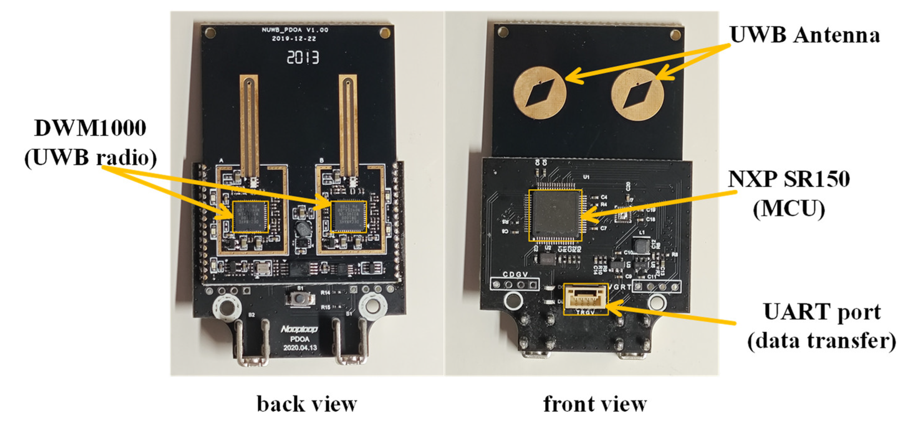
Figure 4.
Point cloud map of the underground parking garage.
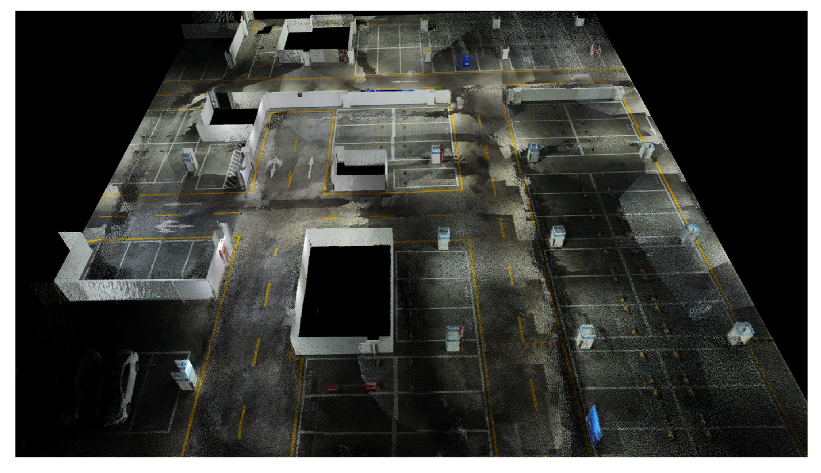
Figure 5.
Geometric model of the underground parking garage.
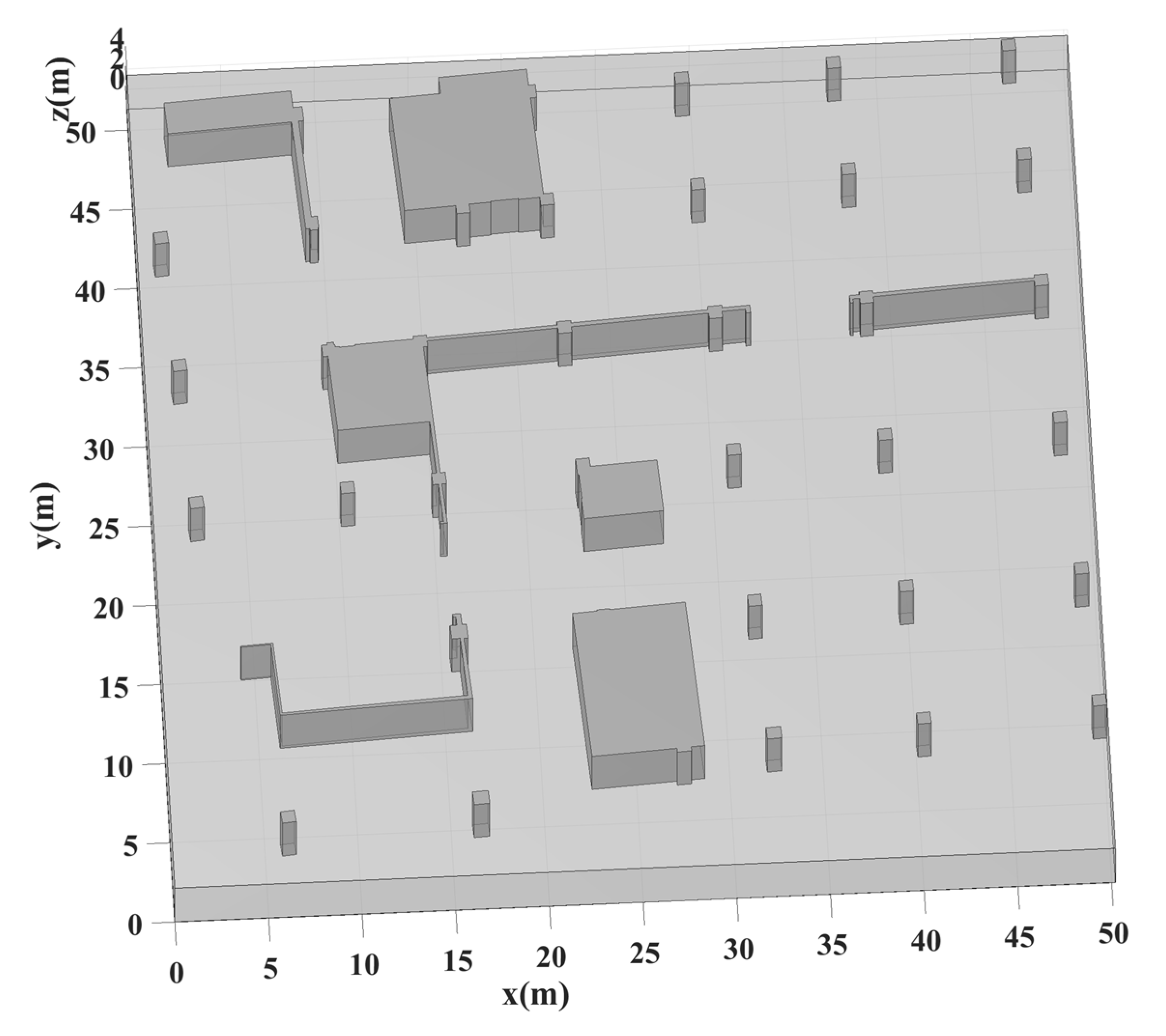
Figure 6.
The integrated system of UWB-Tag and point cloud scanning equipment. The system consists of a UWB tag, inertial measurement unit (IMU) device, and Lixel X1 LiDAR, enabling high-precision 3D positioning and mapping. The scanning equipment provides global coordinate reference while the IMU assists UWB-tag in pose estimation.
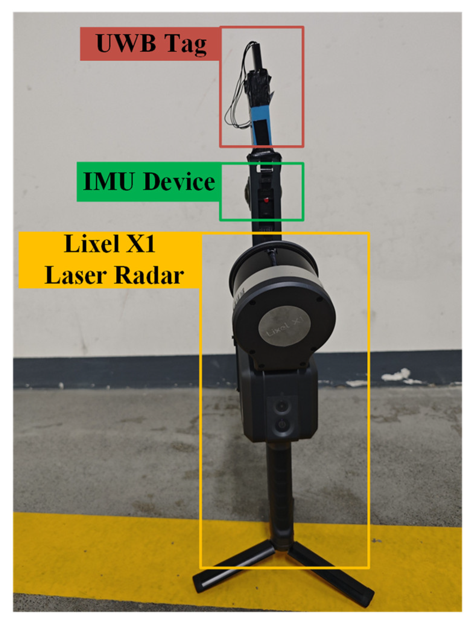
Figure 7.
Layout of UWB anchors and tag trajectory. The figure shows the spatial deployment of four UWB anchors (UWB-0 to UWB-3) in the underground parking garage, and the actual movement path of the UWB tag (from route start to route end).
Figure 7.
Layout of UWB anchors and tag trajectory. The figure shows the spatial deployment of four UWB anchors (UWB-0 to UWB-3) in the underground parking garage, and the actual movement path of the UWB tag (from route start to route end).
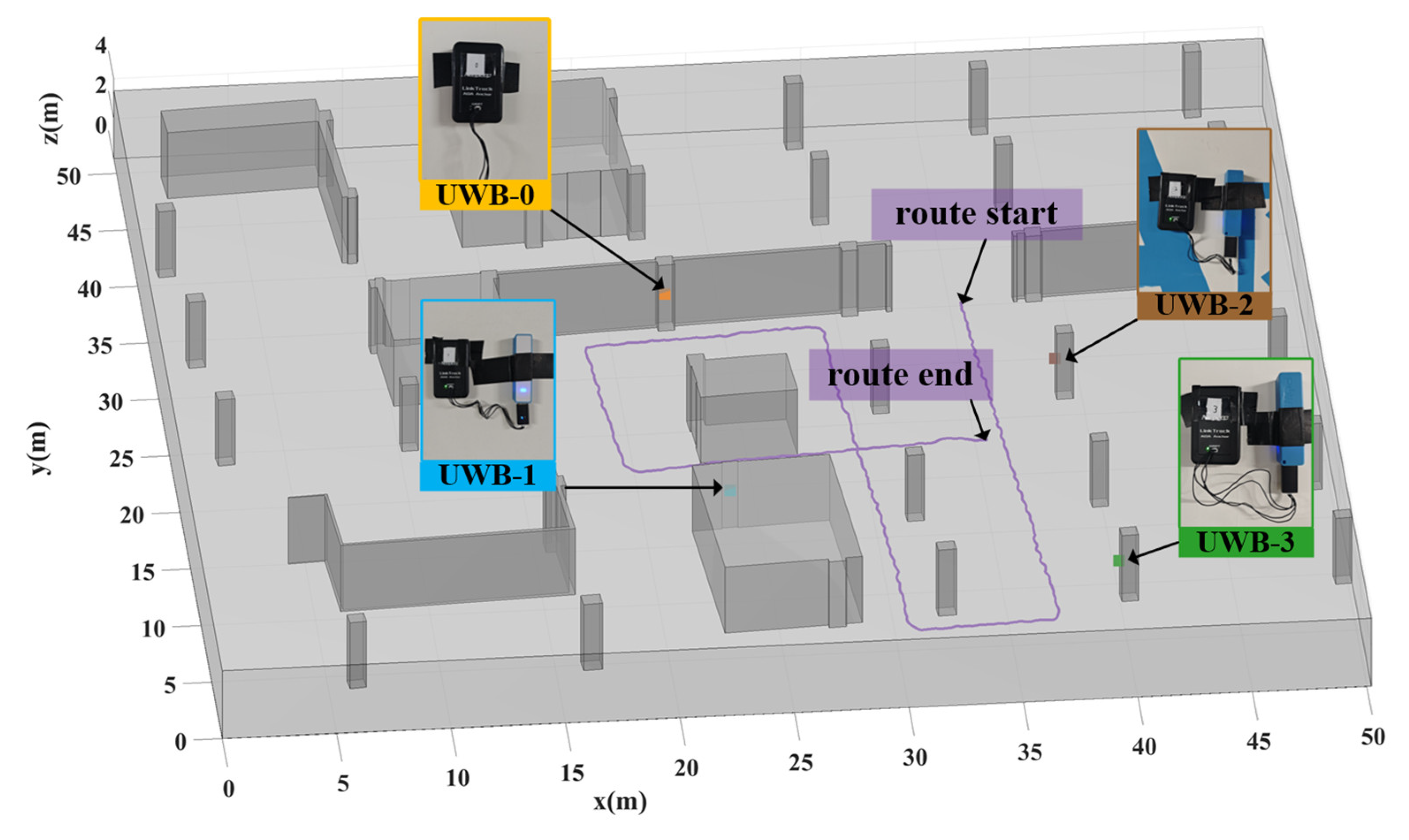
Figure 8.
Distance measurements of UWB anchors.
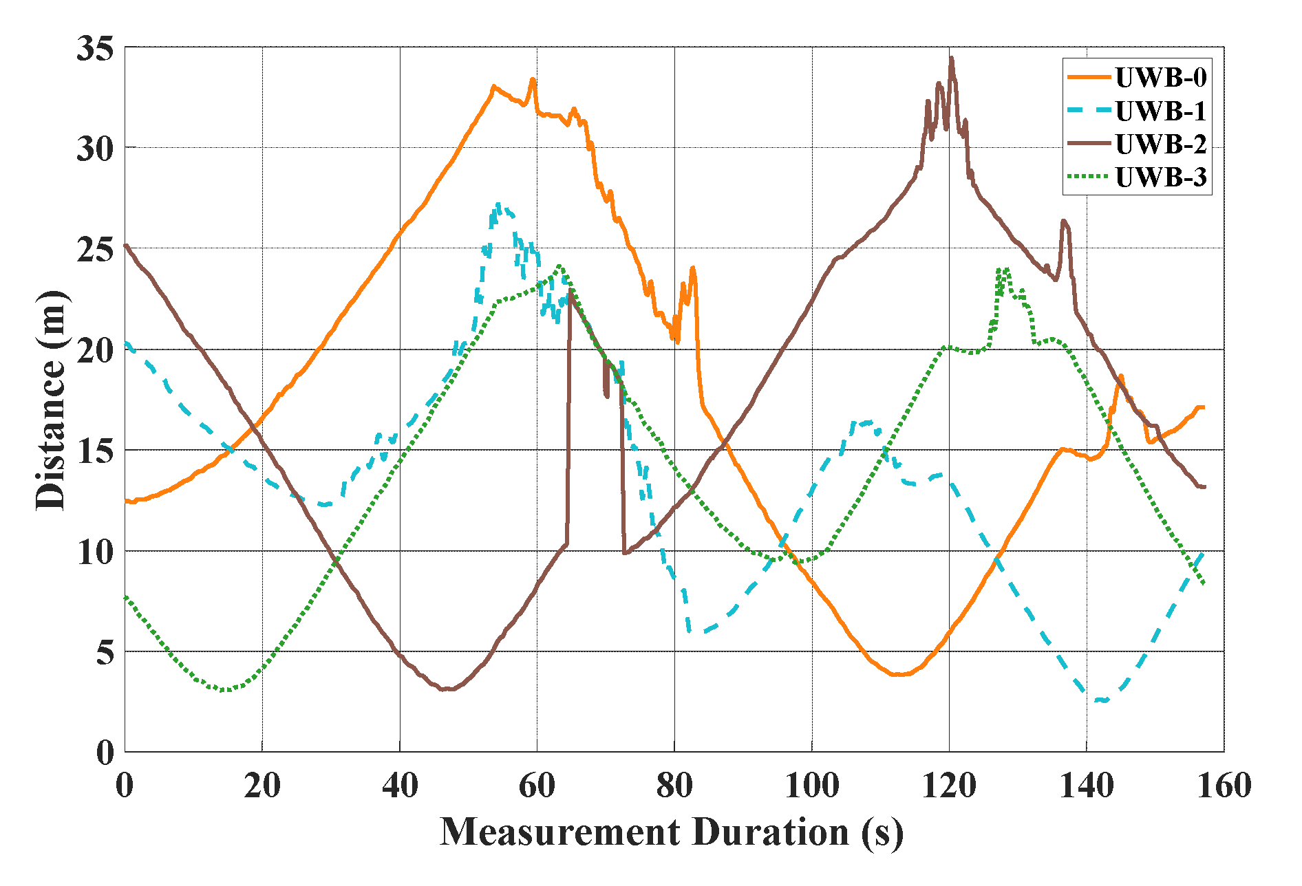
Figure 9.
Arrival of angle measurements of UWB anchors.
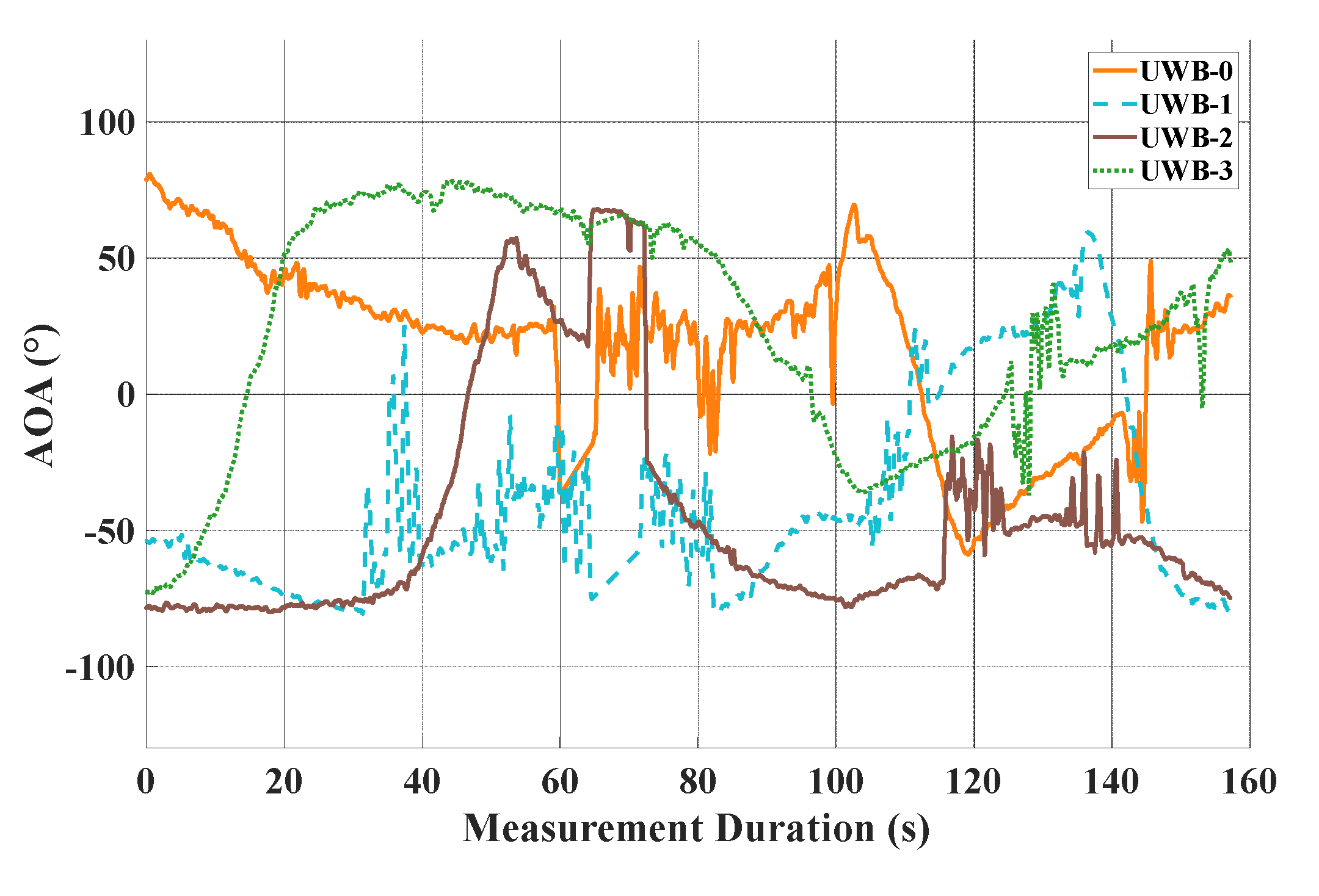
Figure 10.
Received power measurements of UWB anchors.
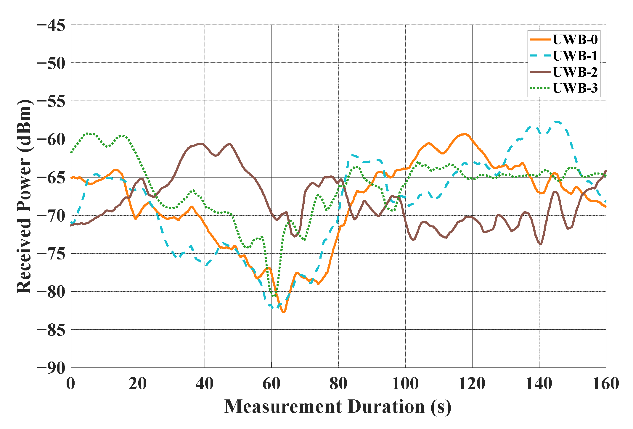
Figure 11.
Comparison of different positioning algorithms with the real trajectory in AOA localization mode.
Figure 11.
Comparison of different positioning algorithms with the real trajectory in AOA localization mode.
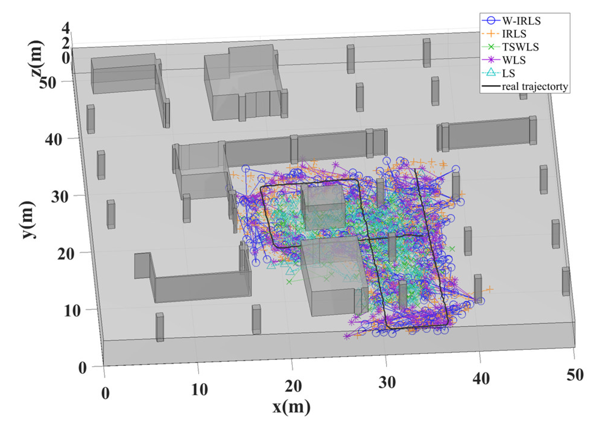
Figure 12.
Comparison of different positioning algorithms with the real trajectory in TOA localization mode.
Figure 12.
Comparison of different positioning algorithms with the real trajectory in TOA localization mode.
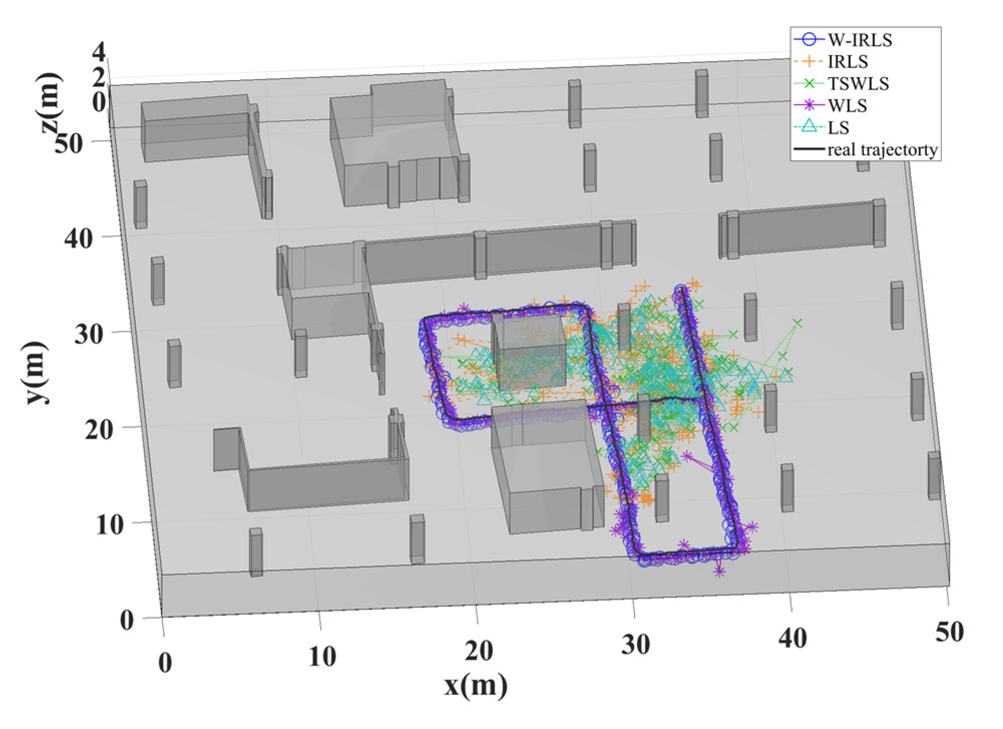
Figure 13.
Comparison of different positioning algorithms with the real trajectory in AOA/TOA hybrid localization mode.
Figure 13.
Comparison of different positioning algorithms with the real trajectory in AOA/TOA hybrid localization mode.
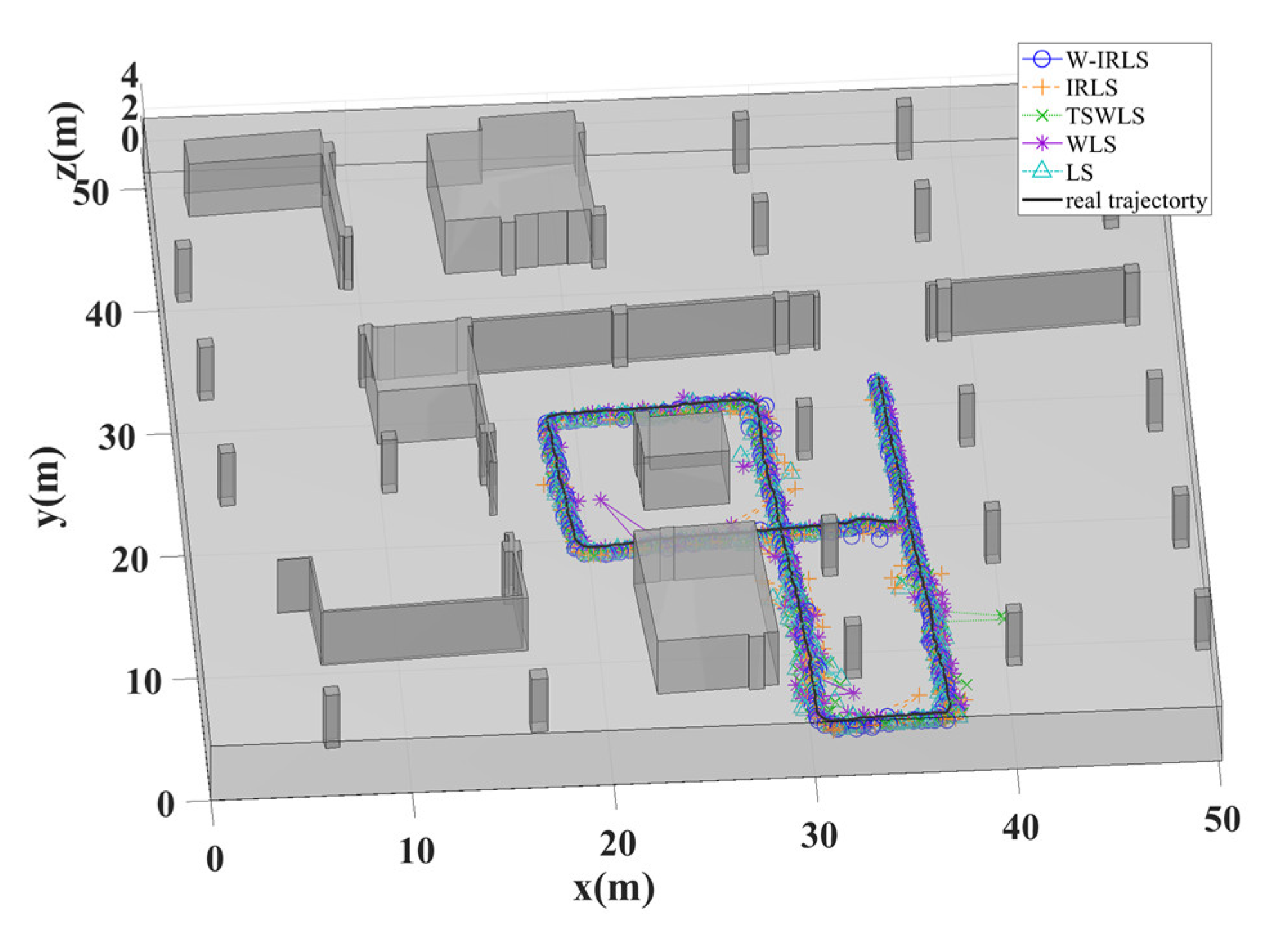
Figure 14.
Comparison of different positioning algorithms with the real trajectory in AOA/TDOA localization mode.
Figure 14.
Comparison of different positioning algorithms with the real trajectory in AOA/TDOA localization mode.
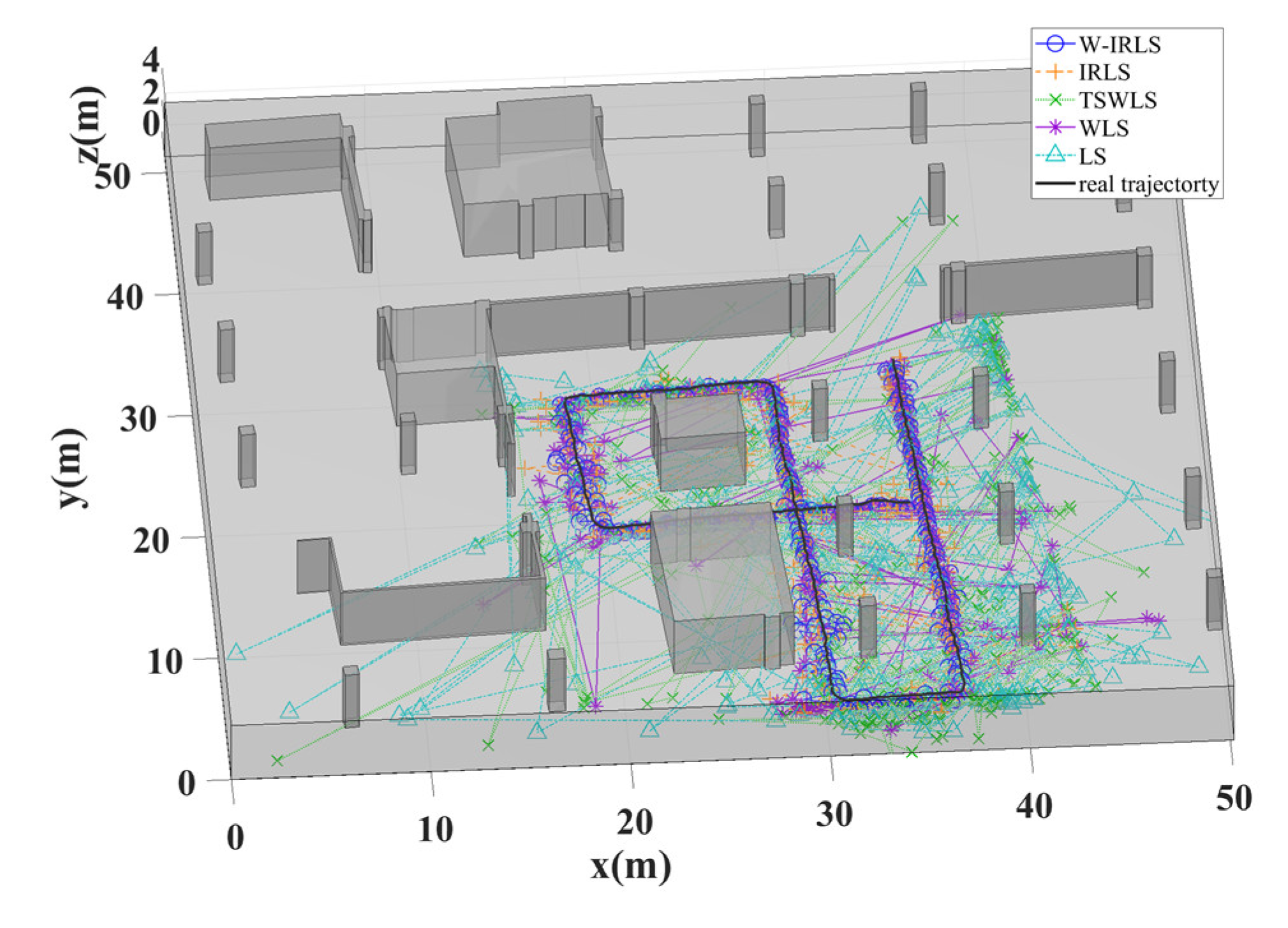
Figure 15.
The CDF of positioning error for different algorithms in AOA localization mode().
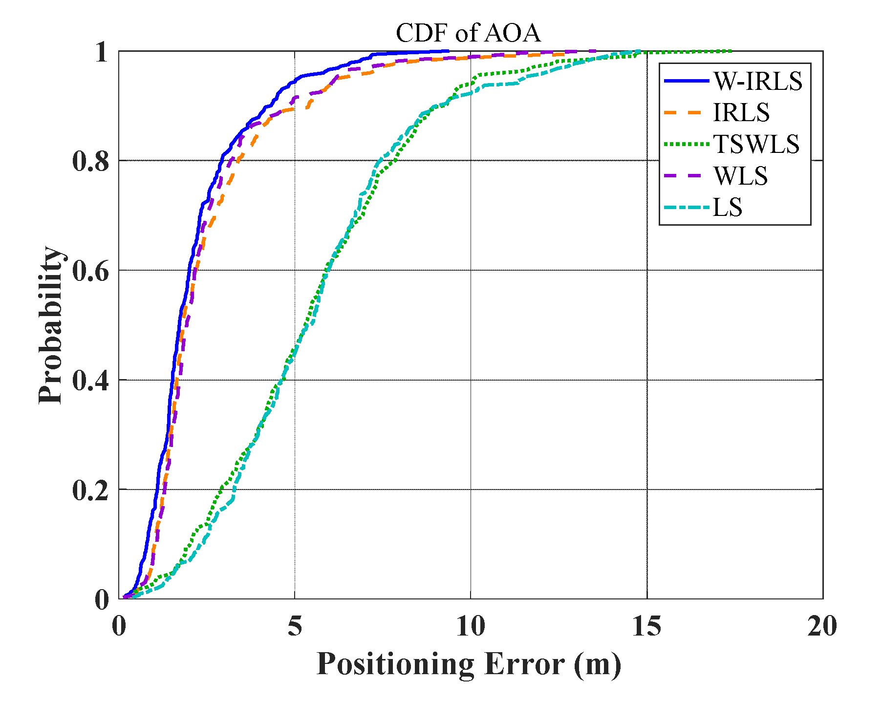
Figure 16.
The CDF of positioning error for different algorithms in TOA localization mode().
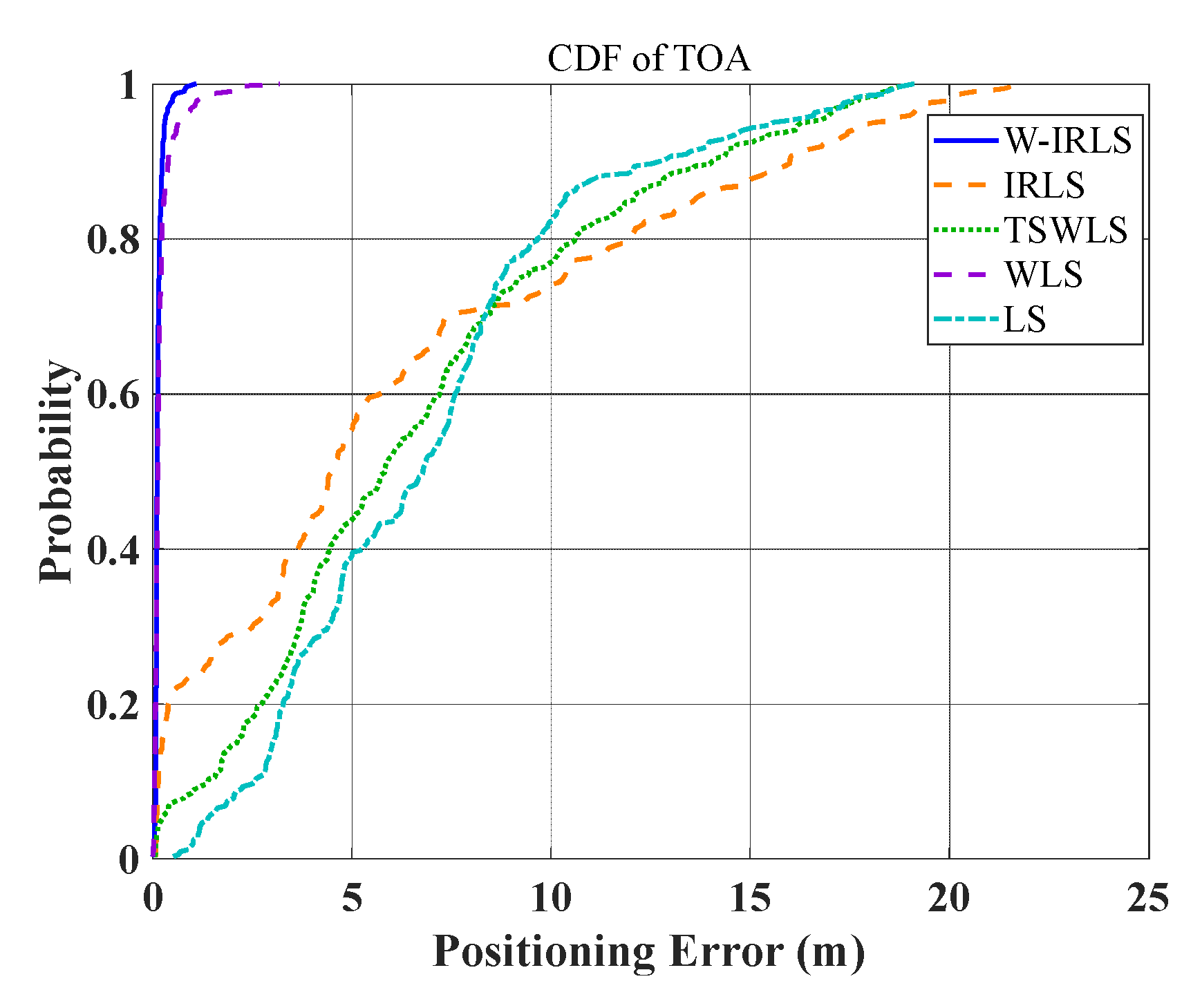
Figure 17.
The CDF of positioning error for different algorithms in AOA/TOA localization mode().
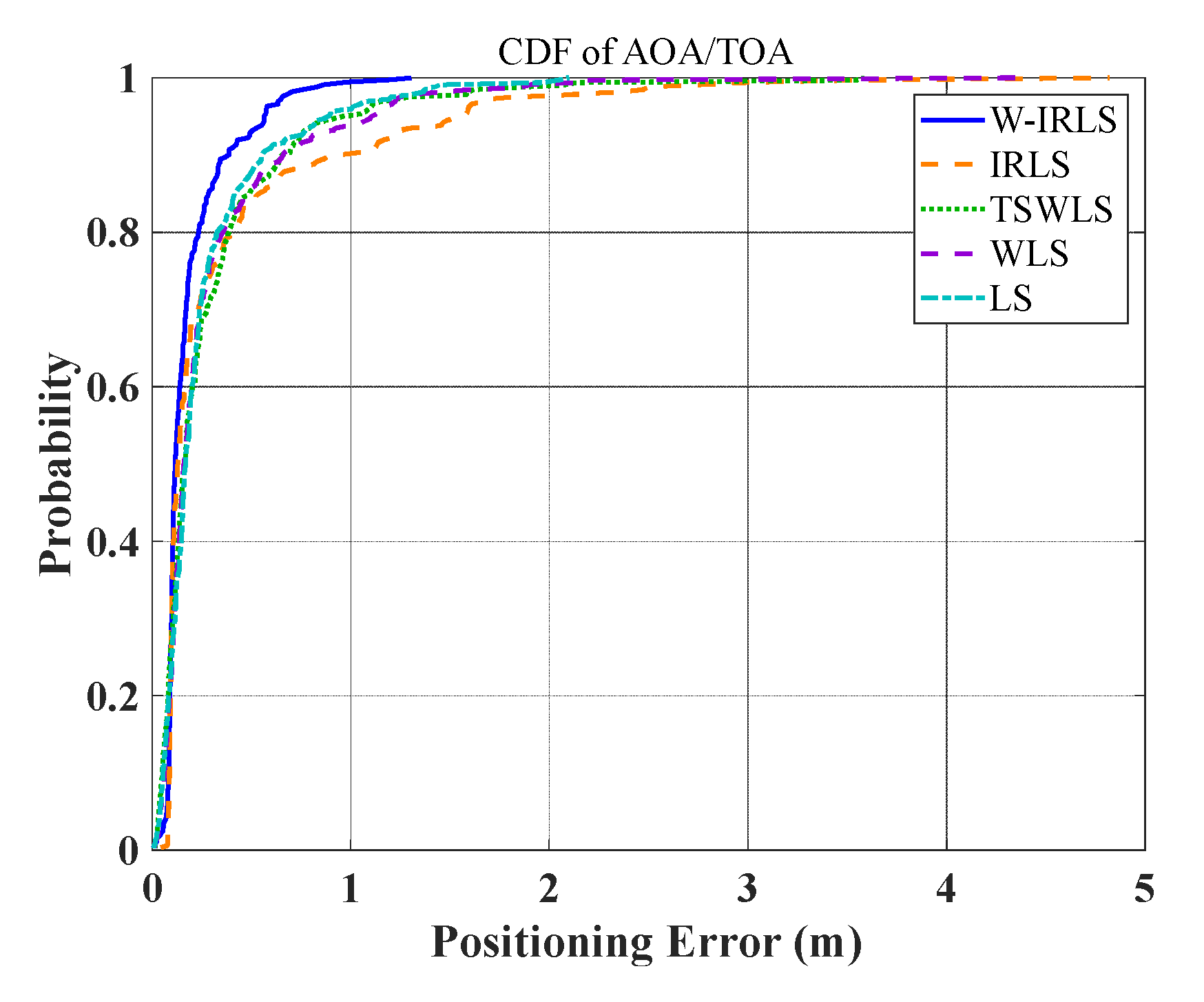
Figure 18.
The CDF of positioning error for different algorithms in AOA/TOA localization mode().
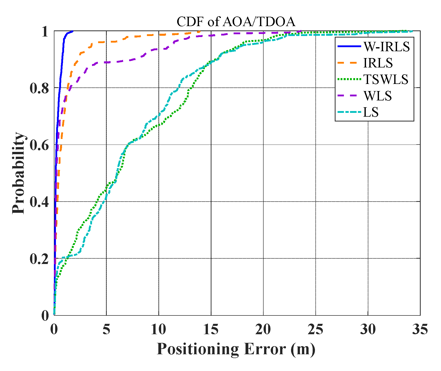
Figure 19.
Simulation environment with horizontal and vertical reflectors. , , and represent anchor positions, with tags placed at points , and .
Figure 19.
Simulation environment with horizontal and vertical reflectors. , , and represent anchor positions, with tags placed at points , and .
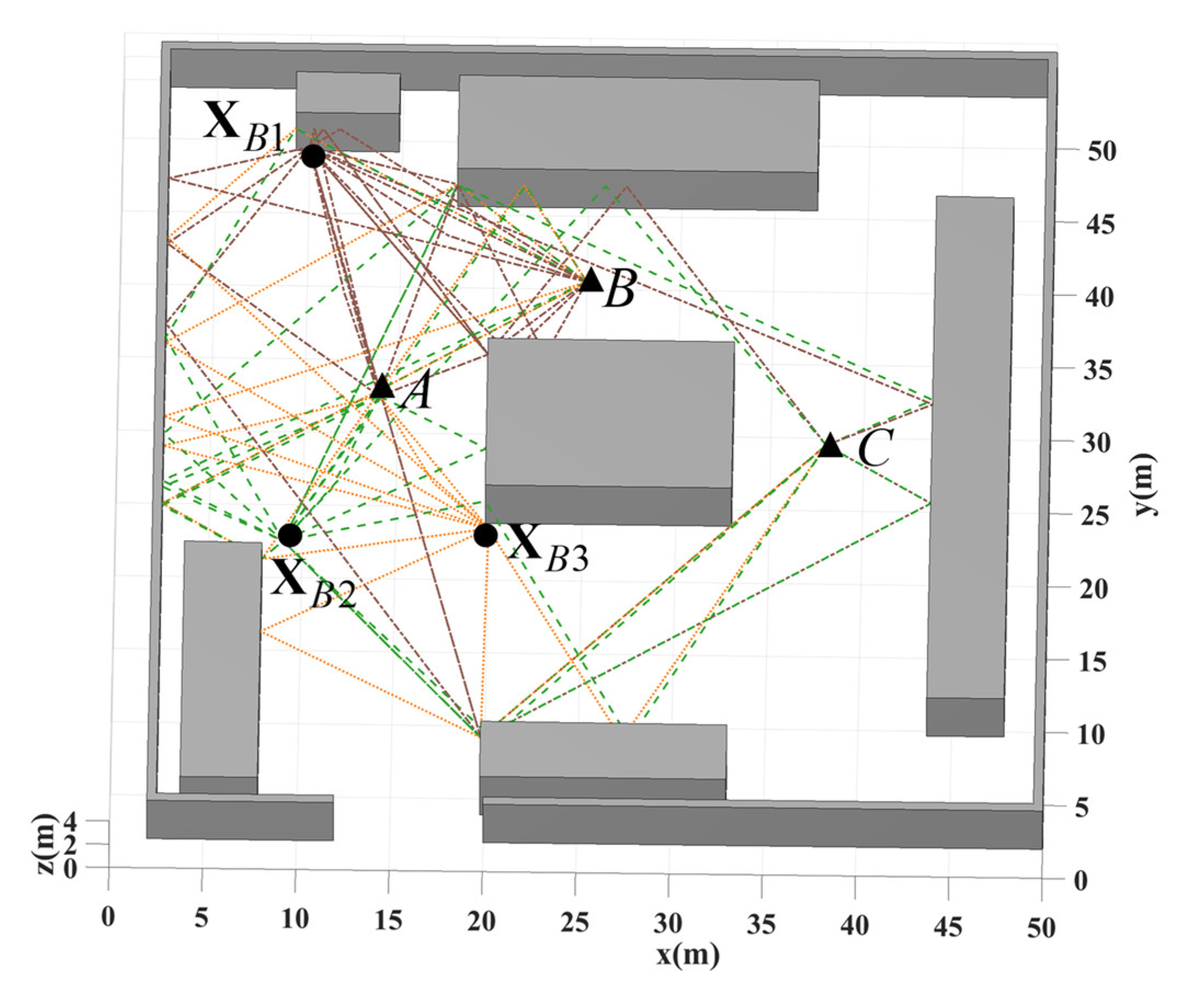
Figure 20.
RMSE performance of scenario A under different localization modes and varying angle error conditions.
Figure 20.
RMSE performance of scenario A under different localization modes and varying angle error conditions.
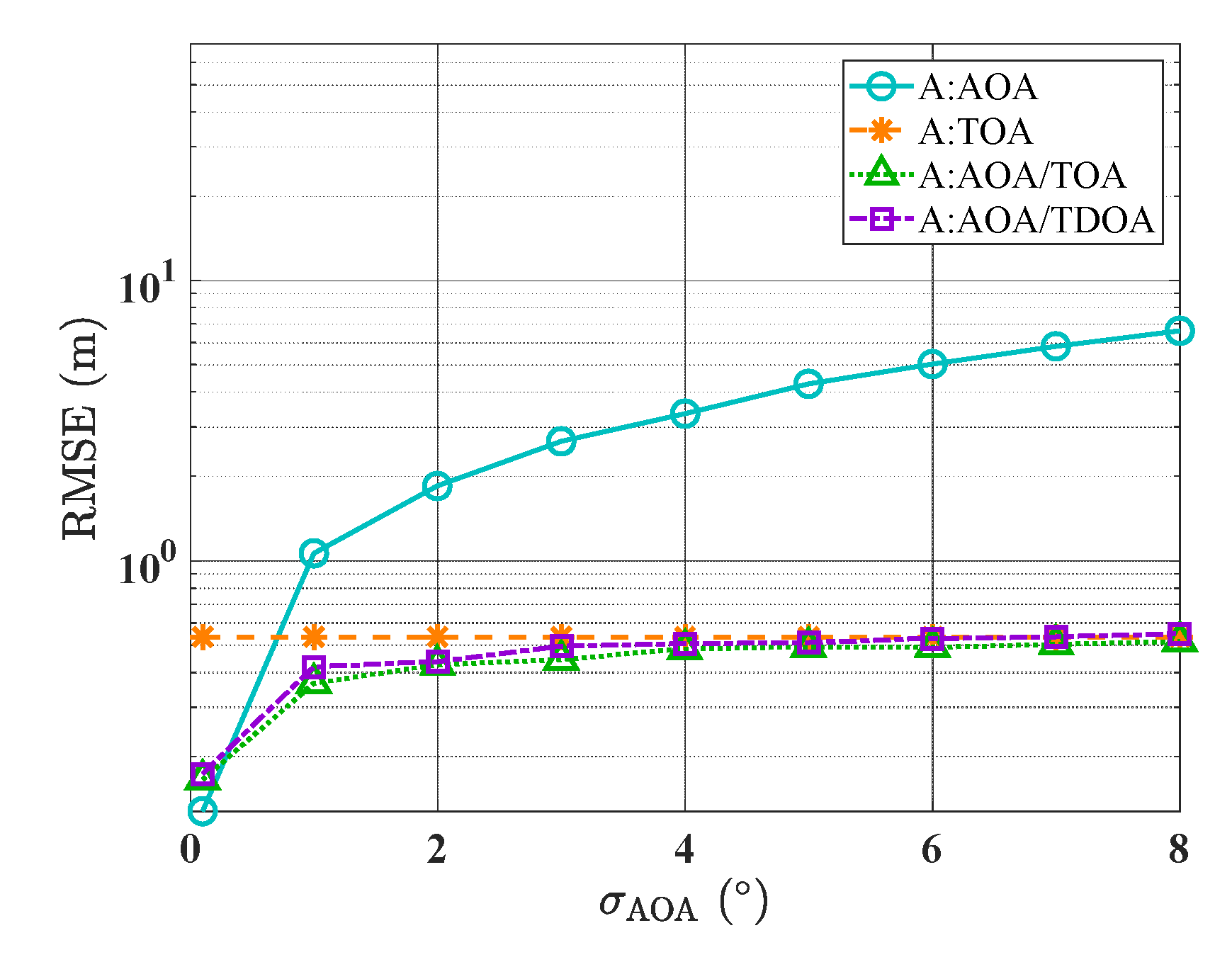
Figure 21.
RMSE performance of scenario B under different localization modes and varying angle error conditions.
Figure 21.
RMSE performance of scenario B under different localization modes and varying angle error conditions.
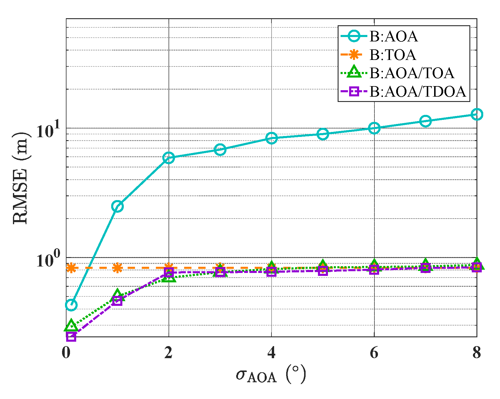
Figure 22.
RMSE performance of scenario C under different localization modes and varying angle error conditions.
Figure 22.
RMSE performance of scenario C under different localization modes and varying angle error conditions.
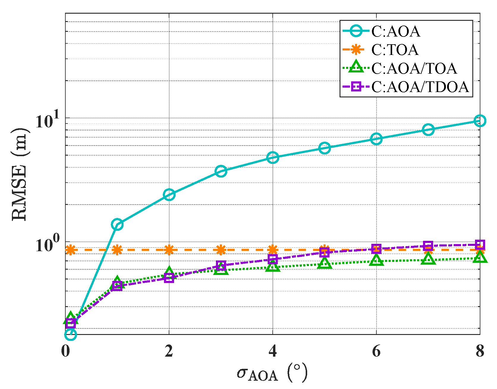
Figure 23.
Schematic diagram of building corner position error. The displacement distance follows zero-mean Gaussian distribution, and is the perturbed coordinate of .
Figure 23.
Schematic diagram of building corner position error. The displacement distance follows zero-mean Gaussian distribution, and is the perturbed coordinate of .
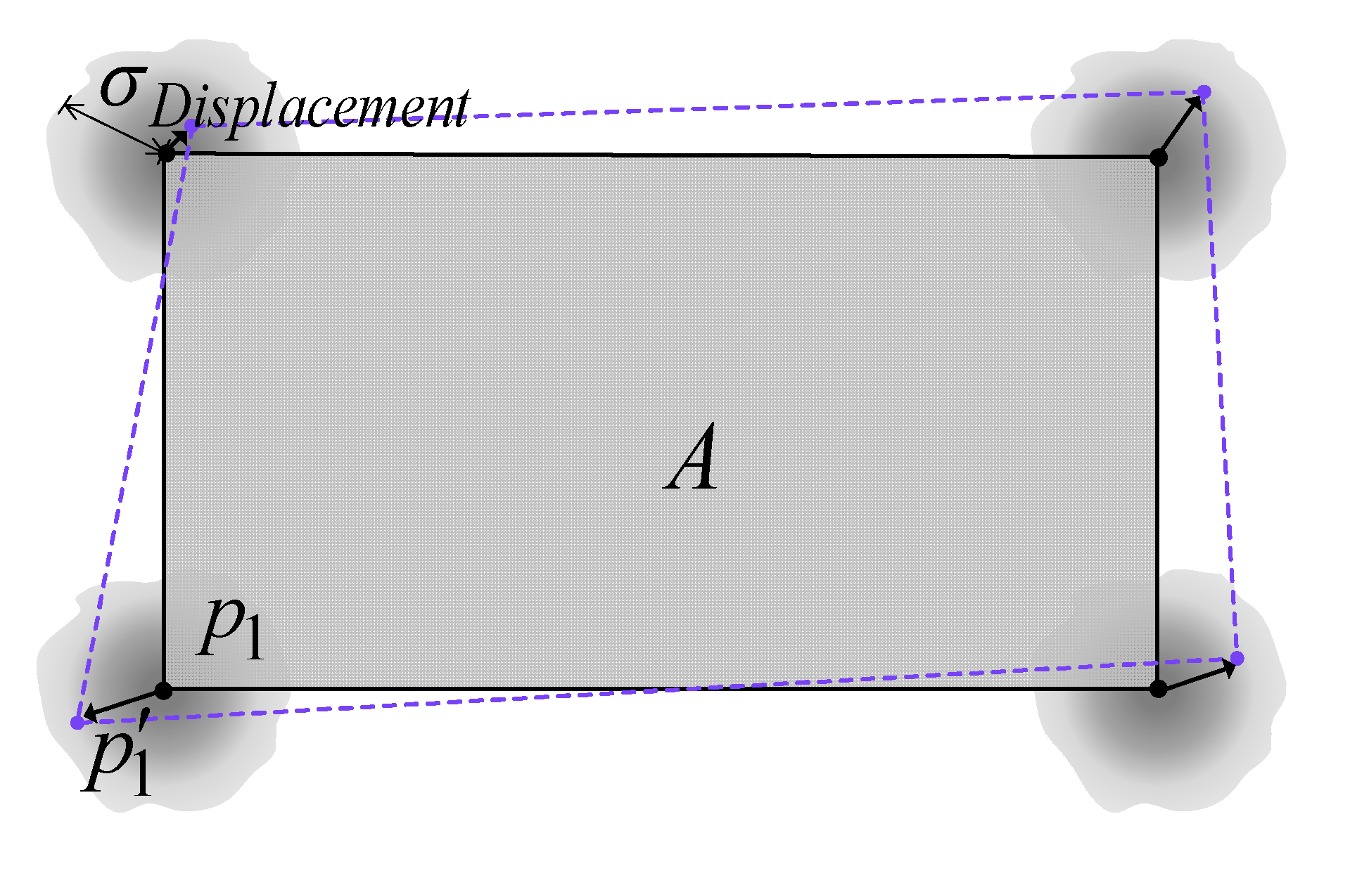
Figure 24.
RMSE performance of scenario A under different localization modes and varying geometric model error conditions.
Figure 24.
RMSE performance of scenario A under different localization modes and varying geometric model error conditions.

Figure 25.
RMSE performance of scenario B under different localization modes and varying geometric model error conditions.
Figure 25.
RMSE performance of scenario B under different localization modes and varying geometric model error conditions.
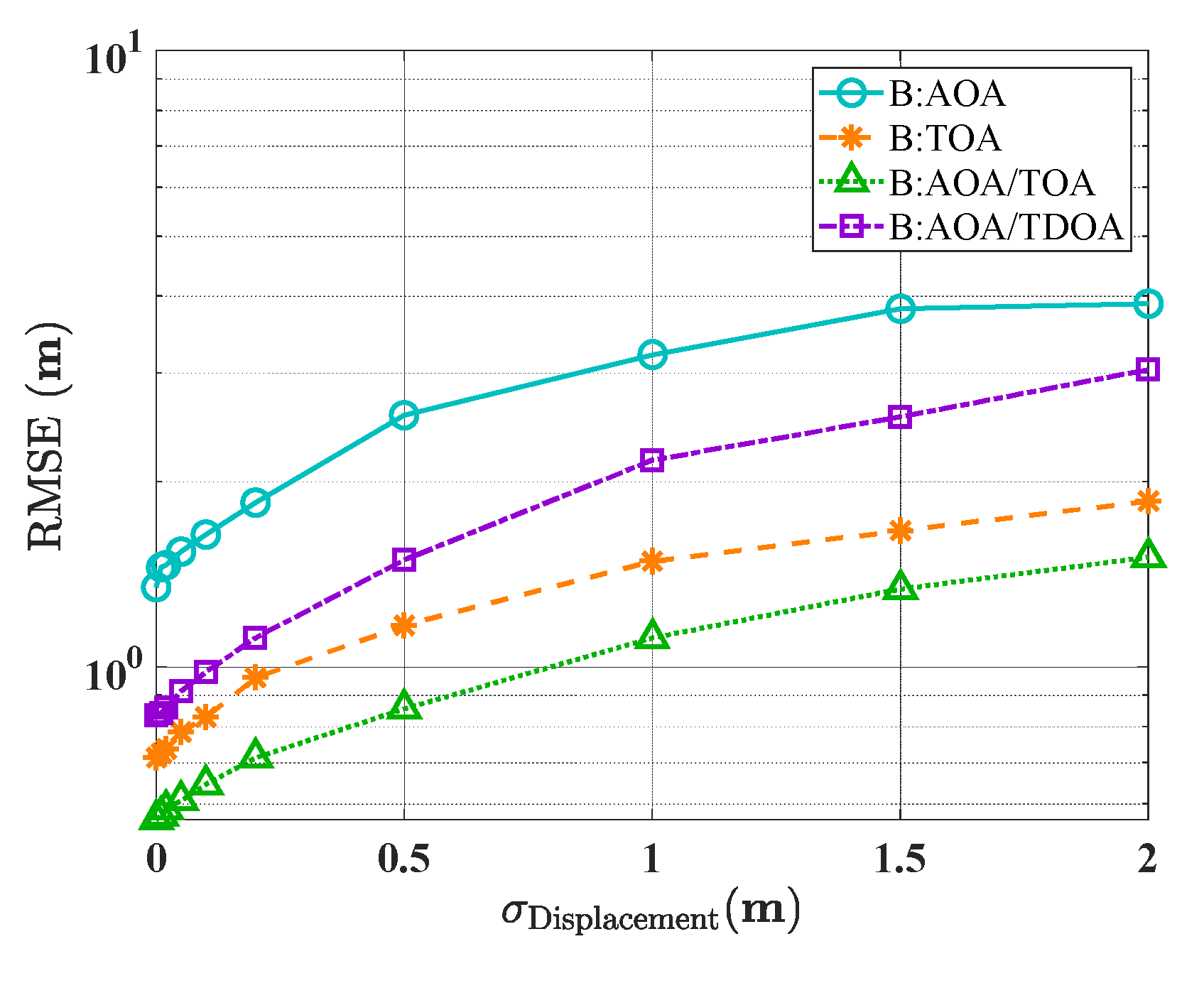
Figure 26.
RMSE performance of scenario C under different localization modes and varying geometric model error conditions.
Figure 26.
RMSE performance of scenario C under different localization modes and varying geometric model error conditions.
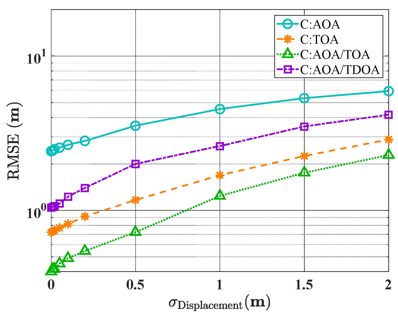

Table 1.
Mean of different algorithms’ ALEs under various localization modes.
| Algorithm | W-IRLS | IRLS | TSWLS | WLS | LS |
|---|---|---|---|---|---|
| AOA | 2.17 m | 2.56 m | 5.53 m | 2.48 m | 5.62 m |
| TOA | 0.18 m | 6.30 m | 6.71 m | 0.21 m | 6.96 m |
| AOA/TOA | 0.14 m | 0.35 m | 0.29 m | 0.29 m | 0.27 m |
| AOA/TDOA | 0.30 m | 1.07 m | 7.25 m | 1.77 m | 7.23 m |
Table 2.
Standard deviation of different algorithms’ ALEs under various localization modes.
| Algorithm | W-IRLS | IRLS | TSWLS | WLS | LS |
|---|---|---|---|---|---|
| AOA | 1.48 m | 1.97 m | 2.86 m | 1.83 m | 2.81 m |
| TOA | 0.17 m | 5.85 m | 4.68 m | 0.32 m | 4.06 m |
| AOA/TOA | 0.12 m | 0.56 m | 0.41 m | 0.41 m | 0.31 m |
| AOA/TDOA | 0.31 m | 1.97 m | 6.19 m | 3.86 m | 6.26 m |
Table 3.
Mean of different localization modes’ ALEs.
| Algorithm | AOA | TOA | AOA/TOA | AOA/TDOA |
|---|---|---|---|---|
| A | 3.23 m | 0.54 m | 0.43 m | 0.46 m |
| B | 7.44 m | 0.83 m | 0.69 m | 0.72 m |
| C | 4.72 m | 0.86 m | 0.58 m | 0.68 m |
Table 4.
Standard deviation of different localization modes’ ALEs.
| Algorithm | AOA | TOA | AOA/TOA | AOA/TDOA |
|---|---|---|---|---|
| A | 3.65 m | 0.33 m | 0.27 m | 0.29 m |
| B | 8.69 m | 0.48 m | 0.46 m | 0.55 m |
| C | 9.21 m | 0.58 m | 0.49 m | 0.51 m |
Table 5.
Mean of different localization modes’ ALEs under unit building displacement error.
| Algorithm | AOA | TOA | AOA/TOA | AOA/TDOA |
|---|---|---|---|---|
| A | 0m | 0m | 0m | 0m |
| B | 1.8m | 0.72m | 0.52m | 1.22m |
| C | 2.0m | 0.98m | 0.83m | 1.67m |
Disclaimer/Publisher’s Note: The statements, opinions and data contained in all publications are solely those of the individual author(s) and contributor(s) and not of MDPI and/or the editor(s). MDPI and/or the editor(s) disclaim responsibility for any injury to people or property resulting from any ideas, methods, instructions or products referred to in the content. |
© 2025 by the authors. Licensee MDPI, Basel, Switzerland. This article is an open access article distributed under the terms and conditions of the Creative Commons Attribution (CC BY) license (http://creativecommons.org/licenses/by/4.0/).
Copyright: This open access article is published under a Creative Commons CC BY 4.0 license, which permit the free download, distribution, and reuse, provided that the author and preprint are cited in any reuse.


