Submitted:
31 December 2024
Posted:
03 January 2025
You are already at the latest version
Abstract
The amount of non-revenue water is around 126 billion cubic meters annually worldwide mostly due to leakage. A more efficient wastewater management strategy would use a parametric design for on-demand customized pipe fittings, following the principles of distributed manufacturing. To fulfill this need, this study introduces an open-source parametric design of a 3D printable easy connect pipe fitting that offers compatibility with different dimensions and materials of the pipes available in the market. Custom pipe fittings were 3D printed using a RepRap-class fused filament 3D printer, with polylactic acid (PLA), polyethylene terephthalate glycol (PETG), acrylonitrile styrene acrylate (ASA), and thermoplastic elastomer (TPE) as filament feedstocks for the validation. The 3D-printed connectors underwent hydrostatic water pressure tests to meet standards for residential, agricultural, and renewable energy production applications. All the printed parts passed numerous hydrostatic pressure tests. PETG couplings can tolerate up to 660±20 psi of hydrostatic pressure, which is eight times larger than the highest standard water pressure for the residential sector. Based on the economic analysis, the cost of 3D printing a pipe coupling is 3 to 17 times lower cost than purchasing a commercially available pipe fitting of a similar size. The new open-source couplings demonstrate particular potential for use in developing countries and remote areas.
Keywords:
Additive Manufacturing
; Distributed Manufacturing
; Fused Filament Fabrication (FFF)
; Sustainable Development
; Design for Additive Manufacturing (DfAM)
; Water Management Systems
1. Introduction
Due to the growing world population [1,2] and the water shortage caused by the climate change crisis [3], there is an increasing demand for drinking water. Global water challenges are also compounded by staggering water loss from leaks. The amount of non-revenue water is around 126 billion cubic meters annually worldwide, which is almost 3.4 times larger than the total annual freshwater withdrawal in Canada [4]. Leakages resulting in treated water turning into wastewater are considered non-revenue water and represent serious challenges with the water management systems. Having leaks not only wastes valuable treated water, but also causes a burden on water supply infrastructures to provide extra pressure to prevent any water contamination [5]. Based on previous studies [6,7], it is well established that the piping system in the majority of developing countries is old and suffers from degradation due to corrosion and environmental conditions [8]. These conditions lead to considerable leakages in the supply system and make up 346 million cubic meters of global non-revenue water per day [9]. Due to the high cost of standard piping equipment and fittings relative to the incomes in developing countries, old components are often not replaced, or non-standard approaches are employed for repair. These choices can waste a significant amount of drinking water and lead to numerous diseases due to water contamination [7,10]. Furthermore, pipe fittings are costly, ranging from CAD$4.80 [11] for lower water pressure, such as domestic applications, to around CAD$18.50 [12] for high pressures and temperatures in industrial applications, according to the specific type of connection, and their supply chain models that are often based on traditional centralized manufacturing[13,14,15,16,17]. In addition, due to expensive maintenance services in developed countries, minor leaks are often neglected, which results in both wasting natural resources and higher pumping costs [18].
The centuries-long trend in centralized manufacturing has been reversed [19] by the introduction of low-cost distributed and localized [20] additive manufacturing (AM). In this regard, the self-replicating rapid prototype (RepRap) project [21,22,23] galvanized the entire AM industry thanks to its open-source approach [24], highlighting the potential of AM, especially fused filament fabrication (FFF), to spread non-centralized manufacturing models. Distributed AM [25] has shown to be a lower cost solution to traditional manufacturing across a wide range of applications [18], including spare parts [27] and consumer goods [28,29,30] or high-end scientific [31,32,33] and medical equipment [34,35]. AM is particularly adept at solving distributed manufacturing problems with customized parts [36,37,38], making on-demand customization affordable for small production batches, e.g., repairs. Thus, introducing 3-D printed plastic pipe fittings can be a potential application for FFF AM in water management. As open-source sharing of 3-D printable design files has been shown to facilitate sustainable development [39,40,41], the technical and economic problems associated with leakage management in water supply systems indicate a promising potential for open-source approaches to mitigate the cost of repair and maintenance in developed countries and standard equipment shortage in remote locations.
Despite this potential application, only two works have explored the capability of using FFF AM to produce piping and fluidic components. In 2018, a study investigated the technical and economic feasibility of EcoPrinting technology by recycling waste polymers and turning them into 3-D printing filaments for humanitarian aid components to prevent water leakage in a village disconnected from the grid and located in a remote jungle area [42]. According to the best practices for sustainable distributed AM [43,44,45], all the equipment used in this study was solar powered [46,47] and they used waste plastic converted via single-screw extruders (recyclebots) [48,49,50] to 3-D printing feedstock to tighten the circular economy loop [51]. During the investigations, designs were modified to reach the goal of having a near-zero carbon footprint [42], and 12 leakages were found and replaced by the 3-D printed pipe couplings designed by the authors. The leakages were fully addressed, although the testing process and the amount of pressure tolerated by the 3D printed components were not reported. Three years later, Price et al. [52] conducted an experimental study on designing and 3D printing an open-source pipe connector for the flow chemistry field. The design consists of a male nut and four connectors with different configurations 3D printed in polylactic acid (PLA), as well as a wetted 3D printed part in polyether ether ketone (PEEK) to prevent any reactions with working fluid. A ferrule is also 3D printed using polypropylene (PP) filaments to prevent leakage. Although the design can perform highly effectively under high pressures, it may not be applicable to water supply systems in residential or industrial sectors due to the difference between the size of the pipe used in the study and the standard pipe diameters for those applications [52].
Although the results in past literature are promising, further research is needed to implement 3D-printed fittings in real applications. A more efficient wastewater management strategy would be introducing an open-source parametric design for on-demand customized pipe fittings, following the principles of distributed manufacturing. This solution can be economically feasible, easy to connect, and compatible with pipes made of different materials and dimensions so that individuals with any skillset can repair their water supply system. Furthermore, these designs need to be validated with testing.
To fulfill this need, this study introduces an open-source parametric design of a 3D printable easy connect pipe fitting that offers compatibility with different dimensions and materials of the pipes available in the market. Different pipe-fitting 3D models were generated by using the new parametric design. The custom pipe fittings were then 3D printed using a RepRap-class FFF 3D printer, selecting PLA, polyethylene terephthalate glycol (PETG), acrylonitrile styrene acrylate (ASA), and thermoplastic elastomer (TPE) as filament feedstocks for the validation. The 3D-printed connectors underwent hydrostatic water pressure tests to meet standards for residential, agricultural, and renewable energy production applications. The manufacturing times and costs were then quantified, and an economic analysis of the new open-source couplings was performed to demonstrate their potential use in developing countries and remote areas. The results are discussed in the context of functional distributed manufacturing.
2. Materials and Methods
2.1. Open-Source Parametric Design
The design and implementation of the pipe fitting model program was written in OpenSCAD 2021.01 [53] and is organized into distinct modules and functions across several files, each with a specific role in constructing the final fitting. A graphical overview of the program workflow can be found in Figure 1, providing an overview of the organization, logic, and functionality of the computational engineering model. The open-source parametric design of this study is available on the Open Science Framework (OSF) under GNU General Public License 3.0 [54]. The approach used ensured that as the components are tightened down they are sealed and there are no sacrificial components.
The parametric design uses threadlib [54] to generate the standard thread types. A summary of the available thread types for the pipe fittings can be found in Table 1. In addition to the built-in thread types listed below, the library offers a method to extend it with additional thread types according to the desired thread standard. The customization interface can be accessed through the ‘pfDesigner.scad’ file, which contains the high-level input parameters accessible to the user. These parameters are fully summarized in Table 2, and the key parameters for customization are indicated in Figure 2a.
The user, at minimum, must enter the desired input diameter and the upper and lower range for the gasket thickness. As shown in Figure 2b, the design interface file will automatically render all valid input options for the input parameters, generating three 3D models for each of them: the cap nut part (on the left), the fitting part (in the middle), and the gasket part (on the right). Note: Using a large gasket thickness range may result in a large number of valid solutions, which could increase the rendering times.
2.2. Pipe Fitting Customization and 3D Printing
Two batches of pipe fitting parts were customized and 3D printed to test the validity of the parametric definition and the reliability of the customizable design and validate the approach. The pipe-fitting 3D models were customized by using the parametric design from Section 2.1. The two batches were customized to demonstrate the use of the parametric design with different kinds of pipes to be fit, which means selecting the “input_dia” parameter as the main variable. This choice led to two solutions working with different pipe diameters with a significant difference in the part dimensions, requiring different manufacturing times and material quantities. The parameters for the customization are shown in Table 3.
After the input selection and rendering, the 3D models were exported as STL files for the slicing. The customized parts for the two batches, Batch 1 (10 mm diameter) and Batch 2 (20 mm diameter), are shown in Figure 3 and are available in the OSF directory [55]. Each rendered pipe fitting solution comprises one cap nut part, one fitting part, and one gasket part, whereas each manufactured assembly includes two cap nut parts, one fitting part, and two gasket parts. Batch 1 comprises three different sets of manufactured assemblies, which differ for the feedstock materials of the cap nut and fitting parts, i.e., PLA, PETG, or ASA. Batch 2 comprises one set of manufactured assemblies using the feedstock material with the best test performances from Batch 1, which means PETG. The gasket parts were all manufactured with the same flexible material, i.e., TPE 85 Shore A, to ensure a tight seal with the pipe fitting under pressure. PLA, PETG, and ASA filaments for FFF were supplied by Polymaker (Shangai, China), whereas TPE was purchased from 3D Printing Canada (Hamilton, ON, Canada). At least three copies were manufactured for each set of assemblies to ensure repeatability, resulting in nine samples for Batch 1 and three for Batch 2 to be tested.
The sample parts were sliced with the open-source PrusaSlicer 2.8.0 (Prusa Research, Prague, Czech Republic) [56]. The gcode files were 3D printed with open-source RepRap class small-format 3D printers, i.e., Prusa XL and Prusa i3 MK3S from Prusa Research equipped with a 0.4 mm nozzle. Being a bowden extrusion system, the Prusa XL was used for the rigid filaments, whereas the direct drive extrusion MK3S was selected to manufacture TPE. The main 3D printing parameters are summarized in Table 3, and the corresponding PrusaSlicer profiles are available in the OSF directory [55].
2.3. Pipe Fitting Testing
The 3D-printed pipe fittings underwent hydrostatic water pressure tests to validate their use for residential, agricultural, and renewable energy production applications. Due to the considerable amount of energy stored in a pressurized air tank, it is prohibited by most international manufacturers and standards to test any plastic pipeline using pressurized air [57,58]. Thus, all the hydrostatic pressure tests were conducted under water pressure using a VEVOR hydraulic pressure test hand pump (Shanghai, China) capable of increasing the water pressure up to 726 PSI. The two main batches of 3D printed pipe fittings underwent at least 16 pressure test processes to ensure the reliability of the test results and the reusability of the 3-D printed fittings and TPE gaskets, comparing the different materials and pipe sizes.
The pressure test was conducted by keeping the same testing conditions for all the 3D printed fittings sizes and materials. It started with a deaeration process by installing the pipe fitting vertically and loosening the top-end nuts until any trapped air inside the test equipment was removed when water was being pumped into the pipes. Accordingly, the main pressure test was conducted in multiple steps for each coupling so that the pressure increased by 50 PSI at each step until any leakage or pressure drop in the equipment was detected. The test was repeated at different torque values, ranging from 5 to 15 Nm for Batch 1 and 7.5 to 17.5 for Batch 2. Also, the time span between the steps was 180 seconds to ensure that the fitting could maintain the pressure without noticeable leakage. The pre-installed pressure gauge on the hand pump had an accuracy of and was calibrated before conducting the experiments.
2.4. Economic Analysis
An economic analysis was performed on the two batches of 3D-printed pipe fittings to validate their suitability in real-world distributed manufacturing contexts, such as developing countries and remote areas, following the method described in [28], which includes material and fabrication electricity costs. The 3D printing times and costs were quantified for each set of samples from both batches, starting from the nominal times and weights reported from the slicing in PrusaSlicer. The nominal times were compared to the real ones, keeping the higher values for the analysis. The nominal weights were calculated using the density of PLA, PETG, ASA, and TPE provided in the datasheet, which means 1.31 g/cm3, 1.25 g/cm3, 1.15 g/cm3, and 1.15 g/cm3, respectively. The actual values were also obtained by weighing the 3D printed parts to acknowledge differences between nominal and real values. The material cost for the economic analysis is considered CAD$27.99 for PLA and PETG [59,60], CAD$38.99 for ASA [61], and CAD$41.98 for TPE per kg of filament [62]. The power consumption of the printers is considered to be 120W according to the nominal power consumption specified by the manufacturer [63]. Finally, the cost of electricity is extracted from the datasheet provided by the Ontario Energy Board from the Mid-Peak price period, which is equal to CAD$0.122/kWh [64].
3. Results and Discussion
3.1. Open-Source Parametric Pipe Fittings
Figure 4 shows the 3D printed parts for both batches obtained from the parametric design in OpenSCAD. The different components were fabricated without the need for support, optimizing the material usage, minimizing waste, and reducing postprocessing timings. As shown in Figure 4a–c, the parts can be 3D printed with different feedstock materials, ranging from more common and inexpensive filaments, e.g., PLA or PETG, to high-performing ones, such as ASA. In addition, the flexible gaskets (Figure 4d) were successfully 3D printed with a medium flexible TPE filament (85 Shore A hardness), and bigger parts can be manufactured without visible defects and the need for supports (Figure 4e). These design choices help make parametric design more accessible to entry-level users and reduce the time to produce customized parts. Furthermore, avoiding supports can contribute to obtaining smoother surfaces and reduce the number of defects due to material removal, increasing the pipe fitting lifespans.
Fluid leakages must be prevented to ensure the reliability of the pipe fitting design during use. To this end, different manufacturing strategies were combined to reduce the risk of leakages of the single parts and the assembled components, as resumed in Table 3. First, the rigid parts were 3D printed with 100% rectilinear infill, aiming to achieve solid parts without internal voids. The extrusion flow was also increased by 5-15% to reduce the risk of interlayer porosity, detachment, or delamination between the different layers and extrusion toolpaths. The overlapping between the infill and perimeters was then adjusted to 20% to achieve a homogeneous deposition within the different cross-sections of the parts. These choices are in line with FFF, as the extrudate bonding between the layers and extrusion toolpaths can be affected by inconsistencies, localized defects, or shrinkage, which may lead to interlayer porosity. In addition, fine-tuning 3D model tolerances facilitated a tight connection between the different parts, especially considering the influence of increased extrusion flow rates on the actual geometry of the components. The TPE gaskets further reduced the assembly leakages, allowing their deformation under pressure to ensure a tight seal between the pipe fitting and nut. For these reasons, the parts did not undergo further postprocessing, such as coatings or heat treatment [65]. This makes the parts easier to manufacture in distributed contexts as they require low-cost FFF 3D printers and fewer raw materials.
3.2. Pipe Fitting Testing
During the pressure test process, the effect of material and pipe dimension was investigated on the highest pressure tolerated by the 3D printed fittings. To check the influence of material on the maximum pressure tolerated by fittings, the parts were 3D printed using PLA, PETG, and ASA based on the pipe diameter of 10 mm and tested under the same working conditions (Batch 1). The fittings were tightened using a torque wrench to investigate the relationship between the tightening torque and the maximum pressure before any leakage, and the torque was raised until physical damage, such as a crack, was observed. The pressure test results for the 10 mm pipe fittings in Figure 5a show that the PETG offers the best performance by tolerating up to 660psi of water pressure, followed by ASA and PLA with 400 and 330 psi, respectively. The figure also shows that the ASA can be tightened up to 15 Nm of torque, while the highest torque for PETG and PLA parts was respectively 12.5 and 7.5 Nm before any cracks appear (refer to Figure 5b,c, and d for the corresponding broken parts). To check the effects of pipe size on the pressure tolerance of the fitting, another sample part was 3D printed using PETG based on 20mm of pipe diameter (Batch 2). Figure 6a shows that the highest pressure achieved by this coupling has been as high as 347psi under 17.5N.m of torque. The lower pressure achieved by 20 mm coupling (Batch 2) compared to the smaller version (Batch 1) can be explained by the fact that larger gaskets need a larger amount of torque to seal the coupling, which explains the crack in the body of the 3D printed coupling in Figure 6b.
3.3. Economic Analysis
The proposed design and manufacturing method for the pipe fittings offer both direct and indirect cost benefits. To show the direct economic benefit, the overall cost of a pipe fitting is calculated and presented in Table 4, which includes the weight of the couplings, material cost, printing time, and the cost of electricity in Ontario, Canada. As is shown in Table 4, the cost of a complete 3D printed pipe fitting for the outer pipe diameter of 10 mm varies from CAD$1.03 for PLA to CAD$1.15 for ASA. A comparison between the cost of a 3D printed pipe fitting and similar commercial pipe couplings (presented in Table 5) clearly shows that the price of a commercial pipe fitting for a similar pipe size and much smaller pressure range can be 4 to 17 times higher than that of for a 3D printed part. Furthermore, the ease of 3D printing a pipe fitting in remote areas where shipping services are either unavailable or expensive, as well as the fact that installing the printed parts does not require any special tools or level of expertise, emphasizes the indirect economic benefits of the proposed approach.
3.4. Impact, Application Context, and Feasibility
According to the International Residential Code (IRC), the static water pressure shall not be greater than 80 PSI. If it exceeds the mentioned limit, a pressure-reducing valve should be installed to lower the static water pressure inside the buildings [66]. Similarly, since the flow rate of the working fluid inside the photovoltaic thermal (PVT) systems is considerably lower than that of the residential sector, the hydrostatic fluid pressure in these systems usually varies between 14 to 44 psi [67,68]. In addition, most irrigation systems inside the greenhouses, such as drip irrigation systems, operate best between 20 and 30 PSI [69]. From this perspective, the new open-source pipe fitting design introduced by the current study ensures tolerating more than 8.2 times higher pressure than the maximum standard pressure in a building and considerably higher pressure than any greenhouse or PVT system requires.
3.5. Future Work
Although further optimization should be done in the future, this study introduces the concept of distributed customizable 3D-printed pipe fittings for water management system applications. Due to the flexibility of the parametric design and the compatibility of the current design with different materials and pipe diameters, the introduced fittings can be the fastest and least expensive choice to build a liquid supply system or to repair a leakage. The open-source CAD design allows for making any other types of pipe fittings with minor code modifications, e.g., three-ways or T junctions. It also allows the user to connect pipes with different outer diameters using only one pipe fitting, which is much more compact and less expensive than commercial pipe couplings.
Apart from the technical and economic advantages of the new design, the independence from the equipment provided by distributed manufacturing methods is another plus point for the current approach. Enabling everyone to design and produce equipment tailored to an existing water supply system makes the current approach capable of being used in space exploration applications, as well as in remote locations, without having access to standard commercial equipment. In addition, thanks to the current user-friendly design, people with any level of technical skill can design or repair their own water supply systems without paying excessive amounts of money for installation and maintenance services.
In addition, the environmental impacts of the current design can be considerably lower than those of commercial plumbing equipment available on the market. For instance, the current pipe coupling can also be 3D printed using recycled plastic [45,49], and the whole pieces of equipment that were used to turn the waste plastic into filaments and the 3D printers can be powered by renewable electricity, e.g., photovoltaics [42,47]. Despite the need for further tests, the 3D printed pipe fittings can also be recycled at their end-of-life through mechanical recycling, resulting in new secondary raw materials for 3D printing, e.g., flakes, pellets, or filaments [45,70]. The resulting recycled materials could then go through multiple recycling processes to keep these resources in use through time [71,72,73], reducing the need of virgin materials for this specific application. These choices can further reduce the costs from the material feedstocks, paving the way for the optimization of this application with secondary raw materials from commodity goods waste.
Although the current design offers higher pressure tolerance compared to what is required for buildings, greenhouses, and renewable energy production applications, an optimization analysis of the fitting mechanism and the dimensions of the pipe coupling can further reduce the production cost as well as the carbon footprint of the new design compared to the conventional approaches.
4. Conclusions
This study introduced an open-source parametric design for 3D printed pipe fittings compatible with waterpipes made of different materials and in various ranges of outer diameter. The parametric design adds substantial flexibility to the piping system while adhering to the existing standards for interoperability.
All the printed parts passed numerous hydrostatic pressure tests. The pressure test results show that PETG couplings can tolerate up to 660±20 psi of hydrostatic pressure, which is eight times more than the highest standard water pressure for the residential sector. Based on the economic analysis, the cost of 3D printing a pipe coupling can be up to 17 times lower than purchasing a commercially available pipe fitting of a similar size.
Future work could use waste plastic to 3D print the pipe fittings at even lower costs while producing piping and plumbing components with considerably lower carbon footprints.
Funding
This work was funded by the Thompson Endowment and The Natural Sciences and Engineering Research Council of Canada.
Conflicts of Interest
The authors declare no competing financial interests.
References
- K. D. R. R.A, “Growing Population and Climate Challenges How To Effects the Future Social Structural Changes and World Conflicts In 21st Century,” SSRN Electron. J., 2020. [CrossRef]
- An Urbanizing World, vol. 55.
- Dhawan, P.; Torre, D.D.; Zanfei, A.; Menapace, A.; Larcher, M.; Righetti, M., “Assessment of ERA5-Land Data in Medium-Term Drinking Water Demand Modelling with Deep Learning,” Water, vol. 15, no. 8, Art. no. 8, Jan. 2023. [CrossRef]
- “Sustainability Insights Research: Lost Water: Challenges And Opportunities | S&P Global Ratings.” Accessed: May 02, 2024. [Online]. Available: https://www.spglobal.com/ratings/en/research/pdf-articles/230906-sustainability-insights-research-lost-water-challenges-and-opportunities-101585883.
- “Experimental Quantification of Contaminant Ingress into a Buried Leaking Pipe during Transient Events.” Accessed: Jul. 17, 2024. [Online]. Available: https://ascelibrary.org/doi/epdf/10.1061/%28ASCE%29HY.1943-7900.0001040.
- Bishoge, O.K., “Challenges facing sustainable water supply, sanitation and hygiene achievement in urban areas in sub-Saharan Africa,” Local Environ., vol. 26, no. 7, pp. 893–907, Jul. 2021. [CrossRef]
- Dighade, R.R.; Kadu, M.S.; Pande, A.M., “Challenges in Water Loss Management of Water Distribution Systems in Developing Countries,” vol. 3, no. 6, 2007.
- Bulti, A.T.; Yutura, G.A., “Water infrastructure resilience and water supply and sanitation development challenges in developing countries,” AQUA — Water Infrastruct. Ecosyst. Soc., vol. 72, no. 6, pp. 1057–1064, Jun. 2023. [CrossRef]
- Liemberger, R.; Wyatt, A., “Quantifying the global non-revenue water problem,” Water Supply, vol. 19, no. 3, pp. 831–837, May 2019. [CrossRef]
- “Energy and Costs of Leaky Pipes: Toward Comprehensive Picture.” Accessed: Jul. 18, 2024. [Online]. Available: https://ascelibrary.org/doi/epdf/10.1061/%28ASCE%290733-9496%282002%29128%3A6%28441%29.
- “Rain Bird Easy Fit 0.5-in Drip Irrigation Compression Fitting Coupling.” Accessed: Nov. 10, 2024. [Online]. Available: https://www.rona.ca/en/product/rain-bird-easy-fit-05-in-drip-irrigation-compression-fitting-coupling-efc25-1pk-32025049.
- “SharkBite K120Z2 EvoPEX Connector x 1/2 Inch MNPT RT, Push-to-Connect, PEX, Misc, Tools & Home Improvement - Amazon Canada.” Accessed: Nov. 10, 2024. [Online]. Available: https://www.amazon.ca/SharkBite-K120Z2-Plumbing-Connector-Misc/dp/B07WRFDKZ7.
- “John Guest 1/4 in. Polypropylene Push-to-Connect Union Fitting,” The Home Depot Canada. Accessed: Nov. 10, 2024. [Online]. Available: https://www.homedepot.ca/product/john-guest-1-4-in-polypropylene-push-to-connect-union-fitting/1001830380.
- “SharkBite ProLock 1/2 inch Push-to-Connect Plastic Slip Coupling Fitting,” The Home Depot Canada. Accessed: Nov. 10, 2024. [Online]. Available: https://www.homedepot.ca/product/sharkbite-prolock-1-2-inch-push-to-connect-plastic-slip-coupling-fitting/1001833994.
- “SharkBite Max 1/2 inch Brass Push-to-Connect Straight Coupling,” The Home Depot Canada. Accessed: Nov. 10, 2024. [Online]. Available: https://www.homedepot.ca/product/sharkbite-max-1-2-inch-brass-push-to-connect-straight-coupling/1000791803.
- “Polypropylene, Philmac & Water Line Compression Fittings | IPEX Inc.,” IPEX. Accessed: Nov. 10, 2024. [Online]. Available: https://ipexna.com/solutions/municipal-solutions/water-service-systems/philmac-compression-fittings/.
- “1/2" Brass Push-Fit Coupling.” Accessed: Nov. 10, 2024. [Online]. Available: https://kent.ca/en/1-2-brass-push-fit-coupling-1006411.
- Blokus-Dziula, A.; Dziula, P.; Kamedulski, B.; Michalak, P., “Operation and Maintenance Cost of Water Management Systems: Analysis and Optimization,” Water, vol. 15, no. 17, Art. no. 17, Jan. 2023. [CrossRef]
- Gwamuri, J.; Wittbrodt, B.T.; Anzalone, N.C.; Pearce, J.M., “Reversing the Trend of Large Scale and Centralization in Manufacturing: The Case of Distributed Manufacturing of Customizable 3-D-Printable Self-Adjustable Glasses,” Chall. Sustain., vol. 2, no. 1, Art. no. 1, Dec. 2014. [CrossRef]
- Srai, J.S.; Graham, G.; Hennelly, P.; Phillips, W.; Kapletia, D.; Lorentz, H., “Distributed manufacturing: a new form of localised production?,” Int. J. Oper. Prod. Manag., vol. 40, no. 6, pp. 697–727, Jan. 2020. [CrossRef]
- Sells, E.; Bailard, S.; Smith, Z.; Bowyer, A.; Olliver, V., “RepRap: The Replicating Rapid Prototyper: Maximizing Customizability by Breeding the Means of Production,” in Handbook of Research in Mass Customization and Personalization, World Scientific Publishing Company, 2009, pp. 568–580. [CrossRef]
- Jones, R. et al., “RepRap – the replicating rapid prototyper,” Robotica, vol. 29, no. 1, pp. 177–191, Jan. 2011. [CrossRef]
- Bowyer, A., “3D Printing and Humanity’s First Imperfect Replicator,” 3D Print. Addit. Manuf., vol. 1, no. 1, pp. 4–5, Mar. 2014. [CrossRef]
- Romero, L.; Guerrero, A.; Espinosa, M.M.; Jiménez, M.; Domínguez, I.A.; Domínguez, M., “Additive Manufacturing with RepRap Methodology: Current Situation and Future Prospects,” 2014, Accessed: May 11, 2024. [Online]. Available: https://hdl.handle.net/2152/88735.
- Salmi, M., “Comparing additive manufacturing processes for distributed manufacturing,” IFAC-Pap., vol. 55, no. 10, pp. 1503–1508, Jan. 2022. [CrossRef]
- Thomas, D.S.; Gilbert, S.W., “Costs and Cost Effectiveness of Additive Manufacturing,” National Institute of Standards and Technology, NIST SP 1176, Dec. 2014. [CrossRef]
- Durão, L.F.C.S.; Christ, A.; Anderl, R.; Schützer, K.; Zancul, E., “Distributed Manufacturing of Spare Parts Based on Additive Manufacturing: Use Cases and Technical Aspects,” Procedia CIRP, vol. 57, pp. 704–709, Jan. 2016. [CrossRef]
- Wittbrodt, B.T. et al., “Life-cycle economic analysis of distributed manufacturing with open-source 3-D printers,” Mechatronics, vol. 23, no. 6, pp. 713–726, Sep. 2013. [CrossRef]
- Petersen, E.E.; Pearce, J., “Emergence of Home Manufacturing in the Developed World: Return on Investment for Open-Source 3-D Printers,” Technologies, vol. 5, no. 1, Art. no. 1, Mar. 2017. [CrossRef]
- Pearce, J.; Qian, J.-Y., “Economic Impact of DIY Home Manufacturing of Consumer Products with Low-cost 3D Printing from Free and Open Source Designs,” Eur. J. Soc. Impact Circ. Econ., vol. 3, no. 2, Art. no. 2, Jul. 2022. [CrossRef]
- Pearce, J.M., Open-Source Lab: How to Build Your Own Hardware and Reduce Research Costs. Elsevier, 2013.
- Coakley, M.; Hurt, D.E., “3D Printing in the Laboratory: Maximize Time and Funds with Customized and Open-Source Labware,” J. Lab. Autom., vol. 21, no. 4, pp. 489–495, Aug. 2016. [CrossRef]
- Pearce, J.M., “Economic savings for scientific free and open source technology: A review,” HardwareX, vol. 8, p. e00139, Sep. 2020. [CrossRef]
- Pearce, J.M., “Distributed Manufacturing of Open Source Medical Hardware for Pandemics,” J. Manuf. Mater. Process., vol. 4, no. 2, Art. no. 2, Jun. 2020. [CrossRef]
- Santos, M.L.; Zacharias, L.R.; Cota, V.R., “Open-source hardware to face COVID-19 pandemic: the need to do more and better,” Res. Biomed. Eng., vol. 38, no. 1, pp. 127–138, 2022. [CrossRef]
- Huang, S.H.; Liu, P.; Mokasdar, A.; Hou, L., “Additive manufacturing and its societal impact: a literature review,” Int. J. Adv. Manuf. Technol., vol. 67, no. 5, pp. 1191–1203, Jul. 2013. [CrossRef]
- Ko, H.; Moon, S.K.; Hwang, J., “Design for additive manufacturing in customized products,” Int. J. Precis. Eng. Manuf., vol. 16, no. 11, pp. 2369–2375, Oct. 2015. [CrossRef]
- Kumar, A.; A. K. Mohanty; Misra, M., “Additive manufacturing technology of polymeric materials for customized products: recent developments and future prospective,” RSC Adv., vol. 11, no. 58, pp. 36398–36438, 2021. [CrossRef]
- Pearce, J.; Blair, C.M.; Laciak, K.; Andrews, R.; Nosrat, A.; Zelenika-Zovko, I., “3-D Printing of Open Source Appropriate Technologies for Self-Directed Sustainable Development,” J. Sustain. Dev., vol. 3, no. 4, Art. no. 4, Nov. 2010. [CrossRef]
- ilkinson, S.; Cope, N., “Chapter 10 - 3D Printing and Sustainable Product Development,” in Green Information Technology, M. Dastbaz, C. Pattinson, and B. Akhgar, Eds., Boston: Morgan Kaufmann, 2015, pp. 161–183. [CrossRef]
- Gwamuri, J.; Pearce, J.M., “Open source 3D printers: an appropriate technology for building low cost optics labs for the developing communities,” in 14th Conference on Education and Training in Optics and Photonics: ETOP 2017, SPIE, Aug. 2017, pp. 550–563. [CrossRef]
- Mohammed, M.I.; Wilson, D.; Gomez-Kervin, E.; Rosson, L.; Long, J., “EcoPrinting: Investigation of Solar Powered Plastic Recycling and Additive Manufacturing for Enhanced Waste Management and Sustainable Manufacturing,” in 2018 IEEE Conference on Technologies for Sustainability (SusTech), Long Beach, CA, USA: IEEE, Nov. 2018, pp. 1–6. [CrossRef]
- Javaid, M.; Haleem, A.; Singh, R.P.; Suman, R.; Rab, S., “Role of additive manufacturing applications towards environmental sustainability,” Adv. Ind. Eng. Polym. Res., vol. 4, no. 4, pp. 312–322, Oct. 2021. [CrossRef]
- Muth, J.; Klunker, A.; Völlmecke, C., “Putting 3D printing to good use—Additive Manufacturing and the Sustainable Development Goals,” Front. Sustain., vol. 4, Jul. 2023. [CrossRef]
- Romani, A.; Rognoli, V.; Levi, M., “Design, materials, and extrusion-based additive manufacturing in circular economy contexts: from waste to new products,” Sustainability, vol. 13, no. 13, 2021. [CrossRef]
- King, D.L.; Babasola, A.; Rozario, J.; Pearce, J.M., “Mobile Open-Source Solar-Powered 3-D Printers for Distributed Manufacturing in Off-Grid Communities,” Chall. Sustain., vol. 2, no. 1, Art. no. 1, Oct. 2014. [CrossRef]
- Gwamuri, J.; Franco, D.; Khan, K.Y.; Gauchia, L.; Pearce, J.M., “High-Efficiency Solar-Powered 3-D Printers for Sustainable Development,” Machines, vol. 4, no. 1, Art. no. 1, Mar. 2016. [CrossRef]
- Baechler, C.; DeVuono, M.; Pearce, J.M., “Distributed recycling of waste polymer into RepRap feedstock,” Rapid Prototyp. J., vol. 19, no. 2, pp. 118–125, Jan. 2013. [CrossRef]
- Cruz, F.; Lanza, S.; Boudaoud, H.; Hoppe, S.; Camargo, M., “Polymer Recycling and Additive Manufacturing in an Open Source Context: Optimization of Processes and Methods,” 2015, Accessed: May 11, 2024. [Online]. Available: https://hdl.handle.net/2152/89441.
- Woern, A.L.; McCaslin, J.R.; Pringle, A.M.; Pearce, J.M., “RepRapable Recyclebot: Open source 3-D printable extruder for converting plastic to 3-D printing filament,” HardwareX, vol. 4, p. e00026, Oct. 2018. [CrossRef]
- Zhong, S.; Pearce, J.M., “Tightening the loop on the circular economy: Coupled distributed recycling and manufacturing with recyclebot and RepRap 3-D printing,” Resour. Conserv. Recycl., vol. 128, pp. 48–58, Jan. 2018. [CrossRef]
- Price, A.J.N.; Capel, A.J.; Lee, R.J.; Pradel, P.; Christie, S.D.R., “An open source toolkit for 3D printed fluidics,” J. Flow Chem., vol. 11, no. 1, pp. 37–51, Mar. 2021. [CrossRef]
- OpenSCAD; OpenSCAD · openscad/openscad. (Feb., 2021). C++, C. Accessed: Sep. 05, 2024. [Online]. Available: https://github.com/openscad/openscad/releases/tag/openscad-2021.01.
- Schlatter, A.; adrianschlatter/threadlib. (Aug., 2024). OpenSCAD. Accessed: Aug. 28, 2024. [Online]. Available: https://github.com/adrianschlatter/threadlib.
- “Design, manufacturing, and economic analysis of parametric open-source 3-D printed easy connect pipe fittings,” Oct. 2024, Accessed: Oct. 08, 2024. [Online]. Available: https://osf.io/fqjxe/.
- “Releases · prusa3d/PrusaSlicer,” GitHub. Accessed: Jul. 01, 2023. [Online]. Available: https://github.com/prusa3d/PrusaSlicer/releases.
- “Standard, A. S. T. M. F2164-13, Standard Practice for Field Leak Testing of Polyethylene (PE) and Crosslinked Polyethylene (PEX) Pressure Piping Systems Using Hydrostatic Pressure. Plastic Pipe Institute.”.
- “2024 Uniform Plumbing Code.” Accessed: May 10, 2024. [Online]. Available: https://epubs.iapmo.org/2024/UPC/.
- “PolyLiteTM PLA,” Polymaker CA. Accessed: Nov. 07, 2024. [Online]. Available: https://ca.polymaker.com/products/polylite-pla.
- “PolyLiteTM PETG,” Polymaker CA. Accessed: Nov. 07, 2024. [Online]. Available: https://ca.polymaker.com/products/polylite-petg.
- “PolyLiteTM ASA,” Polymaker CA. Accessed: Nov. 07, 2024. [Online]. Available: https://ca.polymaker.com/products/polylite-asa.
- “Black Standard TPE85A Filament 1.75mm,” 3D Printing Canada. Accessed: Nov. 05, 2024. [Online]. Available: https://3dprintingcanada.com/products/black-1-75mm-tpe-filament-0-5-kg.
- “Original Prusa XL Semi-assembled Single-toolhead 3D Printer | Original Prusa 3D printers directly from Josef Prusa,” Prusa3D by Josef Prusa. Accessed: Nov. 05, 2024. [Online]. Available: https://www.prusa3d.com/product/original-prusa-xl/#specs.
- “Electricity rates | Ontario Energy Board.” Accessed: Nov. 05, 2024. [Online]. Available: https://www.oeb.ca/consumer-information-and-protection/electricity-rates.
- Mayville, P.J.; Petsiuk, A.L.; Pearce, J.M., “Thermal Post-Processing of 3D Printed Polypropylene Parts for Vacuum Systems,” J. Manuf. Mater. Process., vol. 6, no. 5, Art. no. 5, Oct. 2022. [CrossRef]
- “2018 INTERNATIONAL RESIDENTIAL CODE (IRC) | ICC DIGITAL CODES.” Accessed: May 10, 2024. [Online]. Available: https://codes.iccsafe.org/content/IRC2018P7/chapter-29-water-supply-and-distribution.
- Fudholi, A.; Sopian, K.; Yazdi, M.H.; Ruslan, M.H.; Ibrahim, A.; Kazem, H.A., “Performance analysis of photovoltaic thermal (PVT) water collectors,” Energy Convers. Manag., vol. 78, pp. 641–651, Feb. 2014. [CrossRef]
- Dubey; Tay, A.A.O., “Testing of two different types of photovoltaic–thermal (PVT) modules with heat flow pattern under tropical climatic conditions,” Energy Sustain. Dev., vol. 17, no. 1, pp. 1–12, Feb. 2013. [CrossRef]
- “Drip Irrigation Design Guide-Determining Your Water Source Flow Rate & Pressure,” Irrigation Direct Canada. Accessed: May 10, 2024. [Online]. Available: https://www.irrigationdirect.ca/2008-drip-irrigation-design-guide-determining-your-water-source-flow-rate-and-pressure.html.
- Sanchez, F.A.C.; Boudaoud, H.; Camargo, M.; Pearce, J.M., “Plastic recycling in additive manufacturing: A systematic literature review and opportunities for the circular economy,” J. Clean. Prod., vol. 264, p. 121602, Aug. 2020. [CrossRef]
- Romani, A.; Perusin, L.; Ciurnelli, M.; Levi, M., “Characterization of PLA feedstock after multiple recycling processes for large-format material extrusion additive manufacturing,” Mater. Today Sustain., vol. 25, p. 100636, Mar. 2024. [CrossRef]
- Sanchez, F.A.C.; Boudaoud, H.; Hoppe, S.; Camargo, M., “Polymer recycling in an open-source additive manufacturing context: Mechanical issues,” Addit. Manuf., vol. 17, pp. 87–105, Oct. 2017. [CrossRef]
- Vidakis, N. et al., “Sustainable Additive Manufacturing: Mechanical Response of Polyethylene Terephthalate Glycol over Multiple Recycling Processes,” Materials, vol. 14, no. 5, Art. no. 5, Jan. 2021. [CrossRef]
- “Ipex Philmac 3/4-in ID Quick Disconnect Compression Coupling.” Accessed: Nov. 10, 2024. [Online]. Available: https://www.rona.ca/en/product/ipex-philmac-3-4-in-id-quick-disconnect-compression-coupling-358101-00685560.
Figure 1.
Pipe Fitting Program workflow.
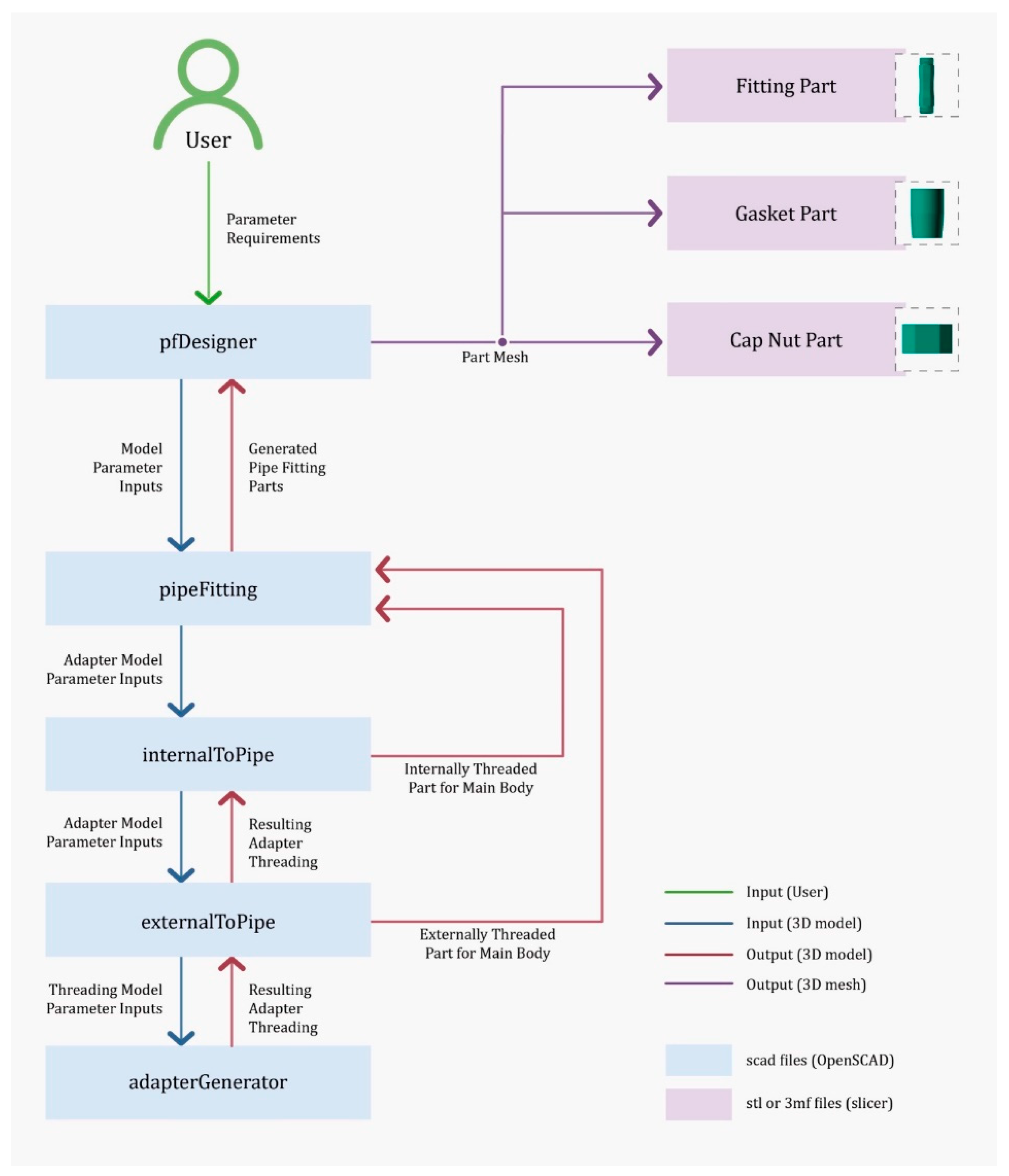
Figure 2.
Customization of the pipe fitting files: (a) List of the labeled parameters of the pfDesigner.scad file modifiable by the users, and (b) preview visualization of the pfDesigner.scad file when the user interacts with the customizable 3D model.
Figure 2.
Customization of the pipe fitting files: (a) List of the labeled parameters of the pfDesigner.scad file modifiable by the users, and (b) preview visualization of the pfDesigner.scad file when the user interacts with the customizable 3D model.
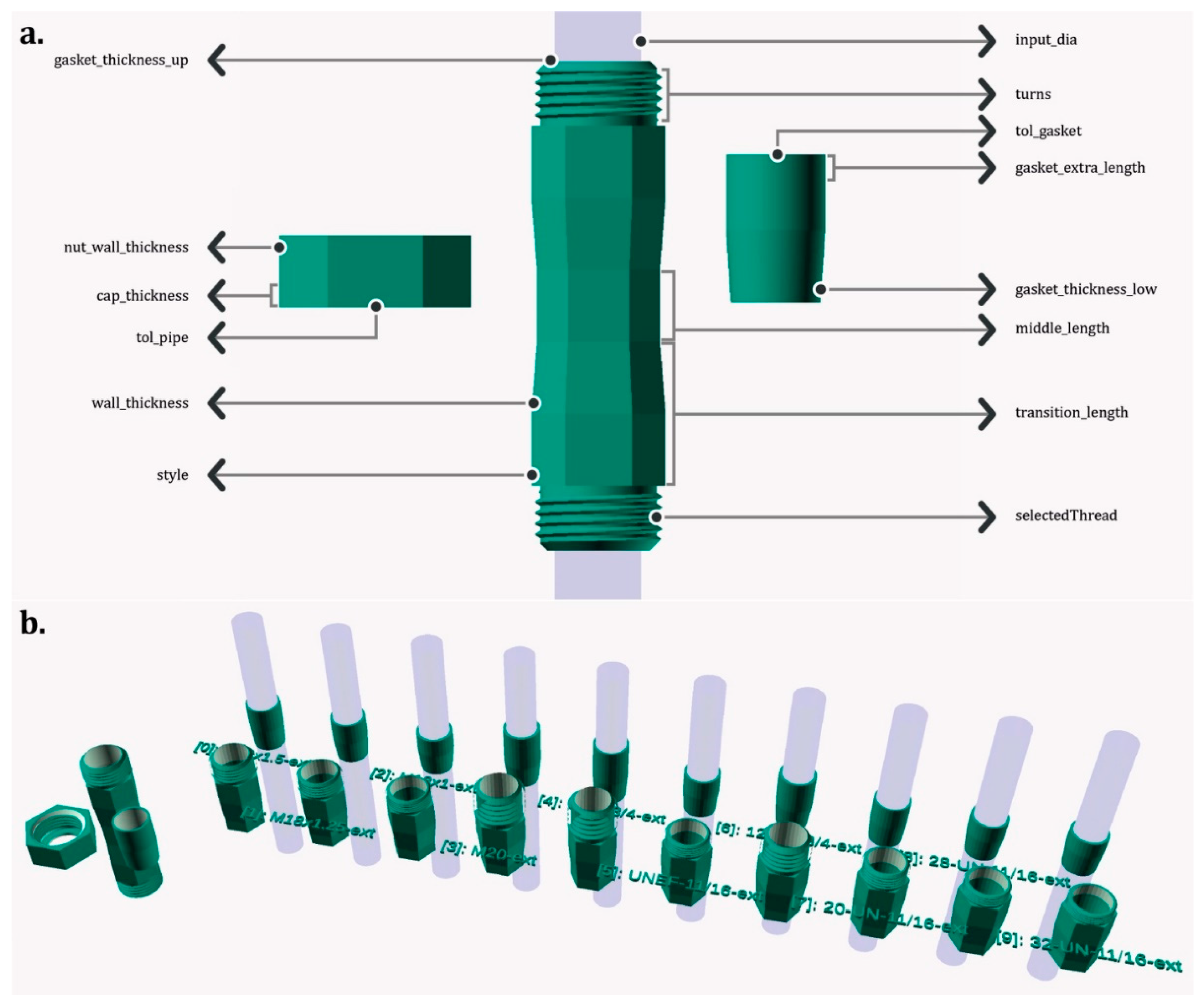
Figure 3.
Stl files of the customized pipe fittings obtained from the pfDesigner.scad file considering (a) a 10mm diameter pipe and (b) a 20mm diameter pipe (from top left to bottom right: fitting part, cap nut part, and gasket part).
Figure 3.
Stl files of the customized pipe fittings obtained from the pfDesigner.scad file considering (a) a 10mm diameter pipe and (b) a 20mm diameter pipe (from top left to bottom right: fitting part, cap nut part, and gasket part).
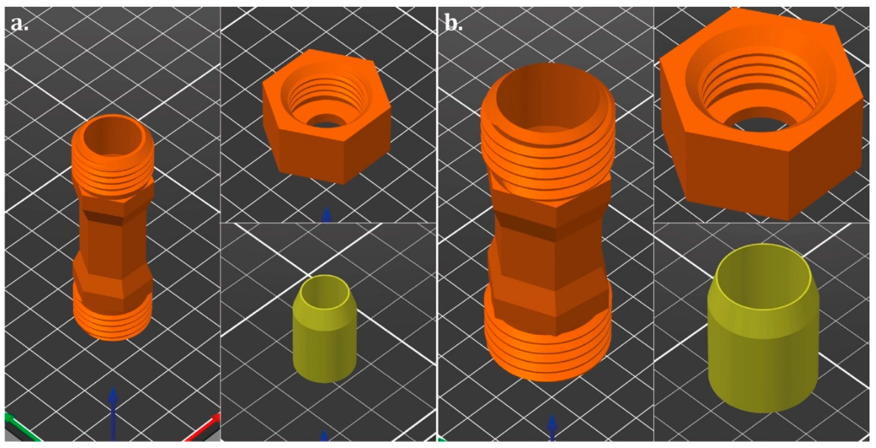
Figure 4.
3D printed pipe fitting parts for the test: (a) 10mm diameter pipe fitting parts made with PLA (from top to bottom: pipe fitting, nut, and assembled parts with the TPE gasket); (b) 10 mm diameter pipe fitting parts made with PETG (from top to bottom: pipe fitting, nut, and assembled parts with the TPE gasket); (c) 10 mm diameter pipe fittings made with ASA (from top to bottom: pipe fitting, nut, and assembled parts with the TPE gasket); (d) 10 mm (top) and 20 mm (bottom) gaskets made with TPE; and (e) 20 mm diameter fitting parts made with PETG (from top to bottom: pipe fitting, nut, and assembled parts with the TPE gasket).
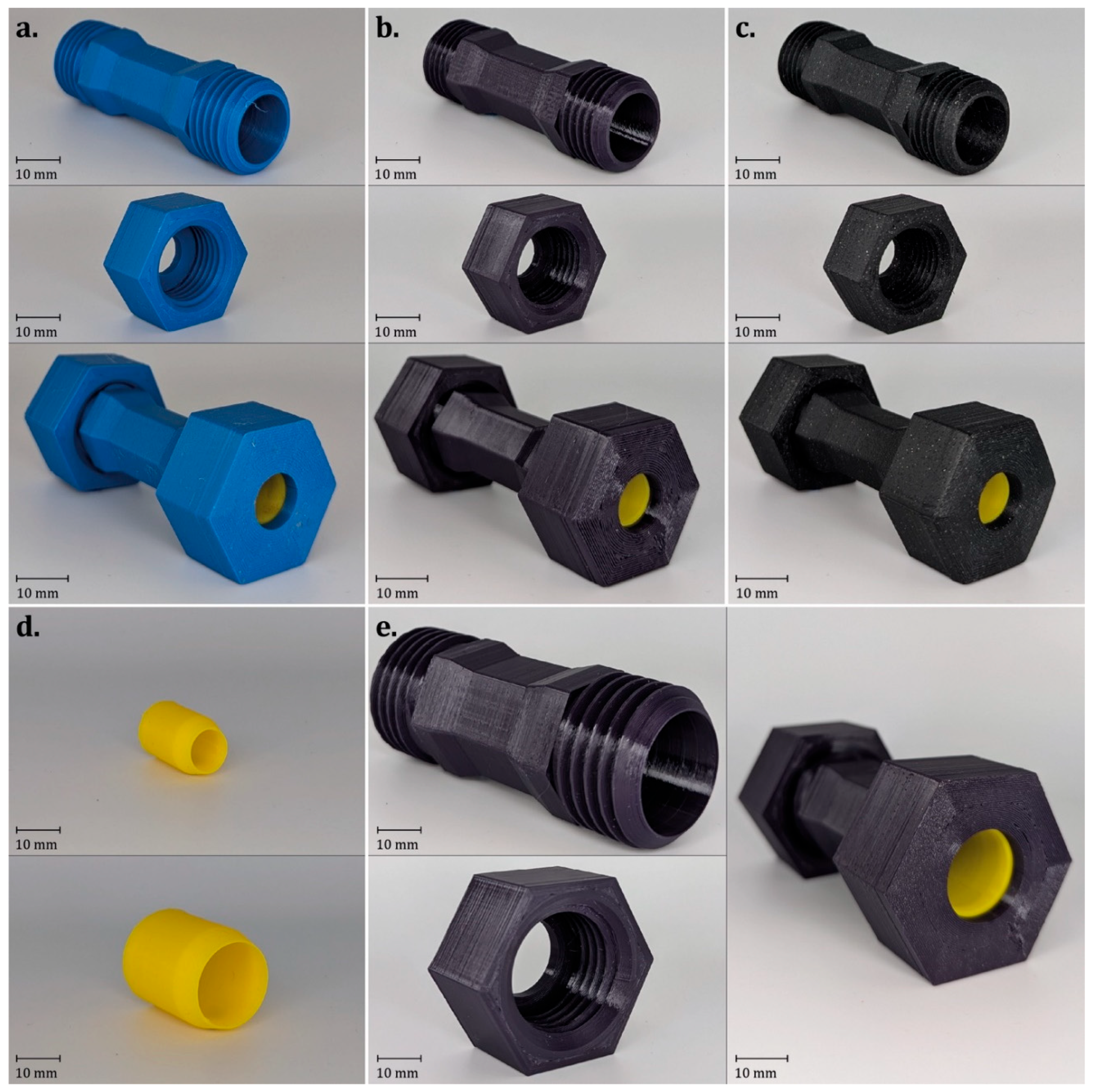
Figure 5.
Hydrostatic pressure tests on Batch 1 (10 mm diameter): (a) average results over time for PLA/TPE, PETG/TPE, and ASA/TPE pipe couplings at different torque; 3D printed parts after the test, showing the status of the components or failures (main body on the left and nut on the right) of (b) fitting parts made with PLA/TPE, (c) PETG/TPE; and (d) ASA/TPE.
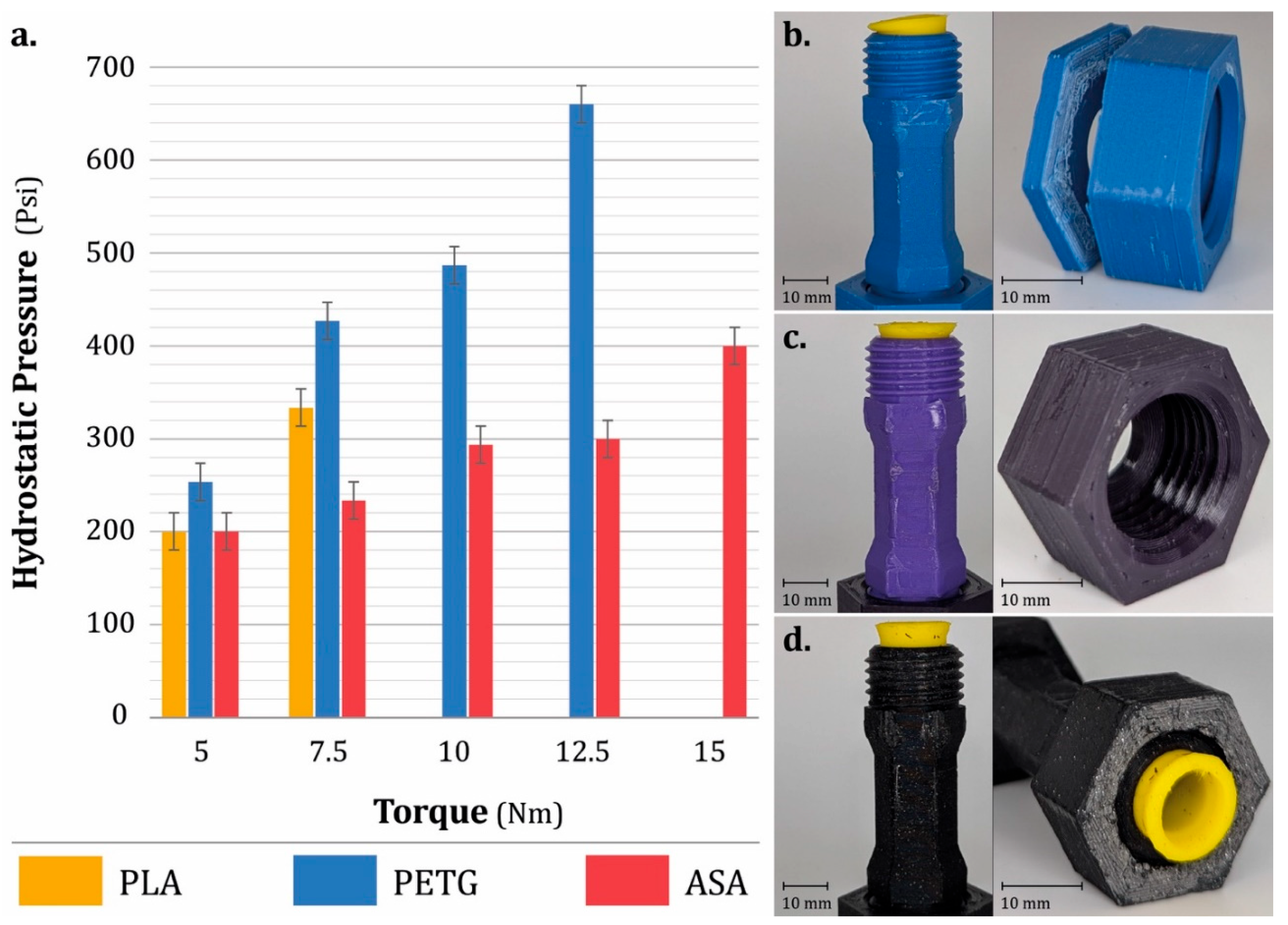
Figure 6.
Hydrostatic pressure tests on Batch 2 (20 mm diameter): (a) average results over time for PETG/TPE pipe couplings at different torque; 3D printed parts after the test, showing the status of the components or failures (main body on the left and nut on the right) of (b) fitting parts made with PETG/TPE.
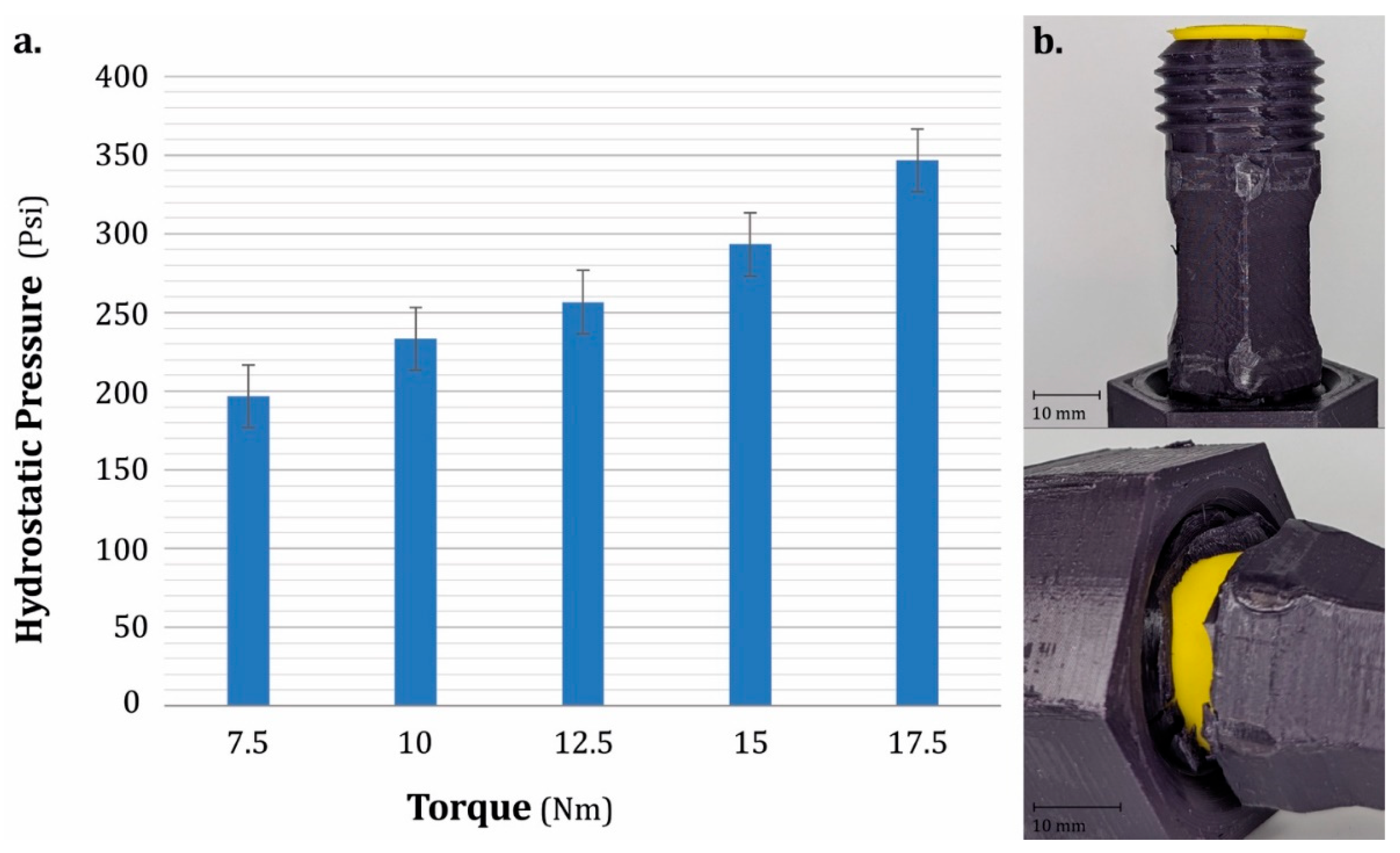

Table 1.
Thread standards available to the user during the customization.
| Thread Type | Range | Details |
|---|---|---|
| Metric Threads | M0.25 to M600 | Coarse, fine, and super-fine pitches |
| Unified Inch Screw Threads (UNC, UNF, UNEF) | Various (UNC, UNF, UNEF) including 4-UN, 6-UN, 8-UN, 12-UN, 16-UN, 20-UN, 28-UN, and 32-UN | All threads are class 2 threads |
| BSP Parallel Thread (G) | G1/16 to G6 | All threads are class A threads |
| PCO-1881 and PCO-1810 | Specific to PET-bottle threads | N / A |
| Royal Microscopical Society's Thread (RMS) | Typical RMS | N / A |
Table 2.
User accessible input parameters/variables (Primary variables define the design, secondary variables modify it, derived variables result from the primary variable combination, and utility variables aid in exporting the final design).
Table 2.
User accessible input parameters/variables (Primary variables define the design, secondary variables modify it, derived variables result from the primary variable combination, and utility variables aid in exporting the final design).
| N. | Input name | Range | Type | Description |
|---|---|---|---|---|
| 1 | input_dia | Primary | The diameter of the input pipe being fit. | |
| 2 | gasket_thickness_upper | Primary | Upper bound on desired gasket thickness. | |
| 3 | gasket_thickness_lower | Primary | Lower bound on desired gasket thickness. | |
| 4 | gasket_extra_length | Secondary | Additional length added to the end of the gasket such that the cap nut compresses it when assembled. | |
| 5 | tol_pipe | Secondary | Tolerance between the pipe and the fitting. | |
| 6 | tol_gasket | Secondary | Tolerance between the pipe and the gasket. | |
| 7 | turns | Secondary | Number of turns for the adapter threading. | |
| 8 | wall_thickness | Secondary | Thickness of the fitting walls. | |
| 9 | middle_length | Secondary | Length of the middle pipe of the fitting. | |
| 10 | transition_length | Secondary | Length of the transition from the middle pipe to the adapter threading begins. | |
| 11 | cap_thickness | Secondary | Thickness of the cover part of the cap nut. | |
| 12 | nut_wall_thickness | Secondary | Thickness of the cap nut walls. | |
| 13 | entry_chamfer | True or false | Secondary | Chamfer around the entry lip of the adapter threads. |
| 14 | style | String input | Secondary | Available options: "Hexagon", "Cone", or "Circular". |
| 15 | selectedThread | Integer | Derived | The desired adapter thread the user wishes to export, must be in range of possibilities. |
| 16 | export | True or false | Utility | Set to true to remove all design possibilities and only display the selected one. |
| 17 | selectedPart | String input | Utility | Available options: "fitting", "nut", "gasket", or "all" to select objects for export. |
Table 3.
Selected parameters used for the customization of the two sample batches and their main 3D printing parameters according to the specific part (pipe fitting, nut, gasket) and material (PETG, PLA, ASA, TPE).
Table 3.
Selected parameters used for the customization of the two sample batches and their main 3D printing parameters according to the specific part (pipe fitting, nut, gasket) and material (PETG, PLA, ASA, TPE).
| Steps | Parameters (Input Name) |
Unit | Batch 1 (10 mm Diameter) |
Batch 2 (20 mm Diameter) |
||||
|---|---|---|---|---|---|---|---|---|
| Customization (OpenSCAD) | Input diameter (input_dia) | mm | 10 | 20 | ||||
| Gasket thickness up (gasket_thickness_upper) | mm | 17 | 19 | |||||
| Gasket thickness low (gasket_thickness_lower) |
mm | 15 | 15 | |||||
| Gasket extra length (gasket_extra_length) |
mm | 6 | 8 | |||||
| Tolerance pipe (tol_pipe) | mm | 0.5 | 0.5 | |||||
| Tolerance gasket (tol_gasket) | mm | 0.1 | 0.1 | |||||
| Number of turns (turns) | // | 5 | 5 | |||||
| Wall thickness (wall_thickness) |
mm | 2 | 2 | |||||
| Lower length (middle_length) | mm | 12 | 12 | |||||
| Mid height (middle_length) | mm | 5 | 7 | |||||
| Cap thickness (cap_thickness) | mm | 3 | 4 | |||||
| Nut wall thickness (nut_wall_thickness) |
mm | 4 | 6 | |||||
| Entry chamfer (entry_chamfer) | // | enabled | Enabled | |||||
| External cross-section style (style) | // | hexagon | Hexagon | |||||
| Selected thread (selectedthread) |
// | 5 | 5 | |||||
| 3D printing (Prusa slicer) | Materials | // | PETG | PLA | ASA | TPE | PETG | TPE |
| 3D printer (Prusa) | // | XL | MK3S | XL | MK3S | |||
| Nozzle diameter | mm | 0.4 | 0.4 | |||||
| Extruder temperature | °C | 240 | 215 | 260 | 230 | 240 | 230 | |
| Bed temperature | °C | 80 | 60 | 105 | 50 | 80 | 50 | |
| Speed | mm/s | 65 | 30 | 65 | 30 | |||
| Infill (Type) | // | Rectilinear | Rectilinear | |||||
| Infill (Overlap) | % | 20 | 20 | |||||
| Infill (Percentage) | % | 100 | 100 | |||||
| Flow (Percentage)a | % | 115-110 | 115-110 | 110-100 | 10 | 110-100 | 100 | |
| Layer height | mm | 0.15 | 0.2 | 0.15 | 0.2 | |||
| Perimeters | // | 6 | 4 | 6 | 4 | |||
| Adhesiona | // | Brim - none | Brim | Brim - none | Brim | |||
a= For PETG, PLA, and ASA, the first value refers to the pipe fitting, whereas the second one refers to the nut.
Table 4.
Economic analysis of the pipe couplings produced with different materials (PLA, PETG, ASA, and TPE gaskets).
Table 4.
Economic analysis of the pipe couplings produced with different materials (PLA, PETG, ASA, and TPE gaskets).
| Custom Design | Material | Parts | Material | Weight (Nominal) | Weight (Measured) | Time | Cost |
|---|---|---|---|---|---|---|---|
| Batch | Unit | // | // | g | g | min | CAD |
| Batch 1 (10 mm diameter) | PLA | Pipe fitting (x1 main body) |
PLA | 12,2 | 10,3 | 82 | 0.31 |
| Nut (x2 parts) | PLA | 21,4 | 20,2 | 61 | 0.58 | ||
| Gasket (x2 parts) | TPE | 3,9 | 3,2 | 45 | 0.15 | ||
| Total assembly | // | 37,5 | 33,7 | 188 | 1.03 | ||
| PETG | Pipe fitting (x1 main body) |
PETG | 11,7 | 10,6 | 80 | 0.32 | |
| Nut (x2 parts) | PETG | 20,4 | 19,7 | 98 | 0.58 | ||
| Gasket (x2 parts) | TPE | 3,9 | 3,2 | 45 | 0.15 | ||
| Total assembly | // | 36,0 | 33,5 | 223 | 1.04 | ||
| ASA | Pipe fitting (x1 main body) |
ASA | 10,1 | 8,4 | 113 | 0.35 | |
| Nut (x2 parts) | ASA | 17,6 | 16,2 | 94 | 0.65 | ||
| Gasket (x2 parts) | TPE | 3,9 | 3,2 | 45 | 0.15 | ||
| Total assembly | // | 31,6 | 27,8 | 252 | 1.15 | ||
| Batch 2 (20 mm diameter) | PETG | Pipe fitting (x1 main body) |
PETG | 28,3 | 29,0 | 146 | 0.85 |
| Nut (x2 parts) | PETG | 69,8 | 71,2 | 296 | 2.07 | ||
| Gasket (x2 parts) | TPE | 11,2 | 8,4 | 125 | 0.38 | ||
| Total assembly | // | 109,3 | 108,6 | 567 | 3.30 |
Table 5.
List of commercially available water pipe couplings for price comparison and economic analysis purposes.
Table 5.
List of commercially available water pipe couplings for price comparison and economic analysis purposes.
| Specifications | Vendor | Material | Pipe Diameter | Pressure Rating [psi] | |
|---|---|---|---|---|---|
| Rain Bird Easy Fit Compression Fitting [11] | RONA | ABS | 16-17 mm | 60 | 4.79 |
| John Guest Push-to-Connect Union Fitting [13] | Home Depot | Polypropylene | 1/4 inch | 150 | 5.13 |
| SharkBite ProLock Push-to-Connect Plastic Coupling [14] | Home Depot | Polymer | 1/2 inch | 160 | 13.16 |
| SharkBite Max Brass Push Coupling [15] | Home Depot | Brass | 1/2 inch | 250 | 13.68 |
| IPEX Philmac Quick Disconnect Compression Coupling [16,74] | RONA | polypropylene | 1/2 inch | 230 | 17.49 |
| Aqua-Dynamic 3/4" Brass Push-Fit Coupling [17] | KENT | Brass | 1/2 inch | 200 | 17.99 |
| SharkBite EvoPEX Connector Push-to-Connect [12] | Amazon.ca | Stainless Steel | 1/2 inch | 200 | 18.44 |
Disclaimer/Publisher’s Note: The statements, opinions and data contained in all publications are solely those of the individual author(s) and contributor(s) and not of MDPI and/or the editor(s). MDPI and/or the editor(s) disclaim responsibility for any injury to people or property resulting from any ideas, methods, instructions or products referred to in the content. |
© 2025 by the authors. Licensee MDPI, Basel, Switzerland. This article is an open access article distributed under the terms and conditions of the Creative Commons Attribution (CC BY) license (http://creativecommons.org/licenses/by/4.0/).
Copyright: This open access article is published under a Creative Commons CC BY 4.0 license, which permit the free download, distribution, and reuse, provided that the author and preprint are cited in any reuse.


