
Submitted:
31 December 2024
Posted:
03 January 2025
You are already at the latest version
Abstract
Effective management of space and connectivity is essential in large-scale power pro-duction systems to generate adequate energy to satisfy market demand. The electric power system is segmented into smaller control zones to more effectively meet the needs of diverse populations, with each zone possessing its independent system. The study aims to design an automated control system for energy production across two interconnected domains: a reheat thermal power plant and a hydropower facility. The system employs fuzzy logic technologies alongside a 2DOF-PID controller to improve control efficacy. The bee swarm optimization approach was employed to facilitate the design and advancements of the fuzzy logic 2DOF-PID controller (FL2DPID). This technique primarily focused on modifying gain and control rules. The fuzzy logic 2DOF-PID controller (FL2DPID) exhibited enhanced performance compared to previous controllers, including fuzzy logic PID, 2DOF-PID and PID controllers. The model achieved a minimal error value of 0.1308, indicating a significant improvement. The data indicate that the new controller is operational, showing a significant improvement in overall performance and the stability of the electrical system.
Keywords:
Automatic Generation Control
; 2DOF-PID Controller
; Fuzzy Logic 2DOF-PID Con-troller
; PID Controller
; Bee Algorithm
1. Introduction
Due to the extensive and intricate nature of the power plant system [1], an area management system and effective linkages are essential for regulating energy production to satisfy current demand. Multiple sub-control regions segment the extensive power system [2]. Each region possesses a distinct control system to optimize power production and effectively address the specific demands of that area with maximum efficiency [3]. A transmission line, commonly known as a tie-line, interconnects each sector, enabling the transfer of power from regions with surplus supply to those with deficits, thereby improving efficiency [4] through optimal use of electrical resources. Integrating large power systems complicates the system's equilibrium and stability maintenance [5]. Improving stability ensures that if an issue arises in one sector, other sectors can help with the provision of electricity. The primary concerns arise from the system's stability, especially during the generation of substantial amounts of electricity. A viable power system must restore stable equilibrium following a disturbance [6]. Automatic Generation Control or AGC is a vital mechanism that improves the stability of the power system by facilitating continuous adjustments in electricity generation to align with customer demands [7]. Consequently, effective management of the electric power system necessitates frequency-load regulation. Load-frequency control (LFC) enables precise power generation adjustments to meet consumption demands while ensuring long-term stability [8]. Controlling power systems is critical to operational effectiveness. The primary goals are as follows: The adequacy of power supply involves controlling the supply to satisfy load demand and prevent interruptions. Reliability refers to the preservation of the electric power system’s equilibrium and the prevention of system fluctuations and interruptions. Quality denotes the capacity to sustain voltage and frequency levels within defined criteria [9]. The electric power system possesses properties that are evolving. Factors influencing the alterations are 1) load variations, 2) generator malfunction and 3) modifications in parameter values [10]. Frequency regulation, which regulates the generator's power output within a designated area, can resolve the stability concerns about the system. The primary goals of AGC is to ensure that, regardless of frequency variations, the system's steady-state error in the transmission line remains zero [11]. This indicates that the system will function in an equilibrium state without residual defects in the transmission line. The system effectively regulates its behavior during transitory situations [12]. The system will respond quickly and reliably to load variations and other circumstances [13]. In the steady state, the system will accurately adjust the generator's operational level according to the power transmission conditions [14-15]. The technology will modify electricity generation to align with load demand and transmission efficiency.
Historically, researchers have devised several control mechanisms to autonomously manage power generation in interconnected power systems. These solutions primarily aim to enhance responsiveness and control efficiency. Frequently used methodologies include:
1). Linear Feedback: This widely utilized classical control technique adjusts electricity generation to align with demand by utilizing data on frequency and power [16]. Despite its straightforwardness in application and understanding, this strategy's efficacy may, in certain circumstances, be inferior to that of alternative methods.
2). Optimal Control [17]: This approach uses mathematical principles to identify the system's optimal control. It can provide optimal efficiency; however, it requires extensive system information and is quite complex.
3). Variable Structure Control [18]: This approach adjusts a control framework based on the system's state. It can be highly adaptable and effective, but it is quite intricate and requires extensive system expertise.
Various alternative control methodologies are available, including intelligent control and fuzzy logic control [19]. Each of these strategies has its own advantages and disadvantages.
Investigations into the application of fuzzy logic in engineering [20] have demonstrated that, in numerous instances, fuzzy logic controllers surpass traditional controllers [21]. Fuzzy logic controllers are an exceptional design choice due to the simplicity of fine-tuning membership functions and control rules. Designers must adeptly adjust control rules and membership functions to get optimal results [22] , despite the challenges posed by design complexity in selecting these values. By examining contemporary operating systems or controllers, the architects of these values can identify efficient methods to calibrate the membership functions and control rules, thus attaining optimal outcomes regarding output error for the performance metrics without relying on trial and error.
The Bee Algorithm (BA) is an effective method for determining optimal parameter values (optimization) [23]. Consequently, diverse controllers employ it to determine their parameters. Historically, the electric power system relied on human oversight. The system will reduce power generation when it exceeds the rated value. The operator must augment power generation if the system frequency falls below the rated value. The outcome is contingent upon the operator's discretion. This approach has limitations as it does not consider the break-even point. Consequently, this issue led to the development of automatic control. The design of fuzzy logic control systems is currently more favorable due to their ability to replicate human decision-making and their flexibility in readily modifying control rules [24]. This research employed a fuzzy logic controller in conjunction with a 2DOF-PID Controller [25] to enhance efficiency. This led to enhanced system performance. Numerous control systems extensively employ fuzzy logic control due to its efficacy in managing non-linear systems without requiring intricate mathematical models. In many cases, the control system is non-linear; therefore, fuzzy logic is an appropriate choice for managing these systems [26].
This study aims to solve problems in large-scale power systems by creating an autonomous power generation control system for two connected hydropower and thermal power plants using fuzzy logic technology and a 2DOF-PID controller. The swarm approach was used to study and design this 2DOF-PID fuzzy logic controller (FL2DPID). This is a useful method for finding the best values for the PID gain, the membership function, and the control rule values, making the power system work better in both domains. This modern technology and methodology allow the power system to adapt precisely and consistently to user requirements, thereby mitigating issues related to long-term balance and stability maintenance.
2. Model of the Reheat Thermal and Hydro Power Systems
To segment the power system for energy generation regulation, each area must be interconnected via transmission lines. Each region interconnects its generators as a unified system [28]. Figure 1 depicts the interconnection between the hydroelectric power plant system and the thermal power plant sectors [29]. Figure 2 depicts the model consisting of two interrelated components: the hydroelectric power plant system and the thermal power plant employed in the operational simulation. The model consists of Area 1, identified as the thermal power plant sector [30], with the main components detailed as follows: Power System 1 utilizes a reheated steam turbine that features a fundamental speed regulator, with the load provided at and the analyzed frequency variation signal as . Area 2 includes the hydroelectric power plant sector, which consists of the following key components: The power system (Power System 2) utilizes water turbines and electrical speed controls to supply the load at [31] and the analyzed frequency variation signal is . The two locations are connected via a coupling transmitter to measure the power change signal . In a stable power supply, all three signals will display low values; high signals may cause damage to the user's electrical equipment [1].
An integrated hydro-thermal system, consisting of two areas, incorporates controllers and a reheat thermal and hydro reheat turbine unit. Figure 2 depicts a block diagram of the continuous-discrete mode technique. It shows how an integrated hydro system (equipped with an electronic governor) operates in conjunction with a thermal system that incorporates a reheat turbine, as well as other components. In the continuous-time framework, the state-space formulas describing the electric power system can be formulated as outlined below:
where matrix for system, matrix for input and matrix for distribution of disturbances, respectively and these matrices are derived from the formulas presented in Appendix A. The status vector, x(t) is formed from the vector control, u(t) vector disturbance. d(t) that represent burden changes are expressed as outlined below:
where Δ signifies a divergence from standard values, ending 1 denotes the reheat thermal area and ending 2 indicates the hydro area.
System output, dependent on the ACE shown in Figure 2, is articulated as outlined below:
where C matrix for output.
This article uses traditional PID and optimum FL2DPID controllers to govern the system in question. The following equation represents the control signal for conventional FL2DPID controllers in the discrete mode shown in equations 7-8.
3. Controller Structure
The two transfer functions in closed loops dictate the performance of the 2DOF-PID controller [32], which was found to be superior compared to the one degree of freedom controller. The FL2DPID controller [33] part about the suggested controller calculates a weighted difference among the feedback signals (measured system output) and the reference signal R(s). This difference is based on the set point weights for each proportional, integral, and derivative action. The selected gain settings assign weight to each action, and the controller output combines the outputs from all individual actions on the relevant difference signals. show in Figure 3.
Figure 4 illustrates the four essential components of a fuzzy logic controller: the fuzzifier, inference engine, regulation guideline and de-fuzzifier. Fuzzification is the process of using a fuzzifier to convert numerical data into fuzzy set values. The inference engine is the essential component that oversees the logic optimization of the fuzzy logic controller in the fuzzy logic control framework. The rule set comprises membership functions (Figure 5) and regulation guideline (Figure 6). The fuzzy set captures the outcome of the inference process. However, even after a de-fuzzifier converts the fuzzy set numerically, a process known as defuzzification, the fuzzy logic controller must generate a numerical output [34].
Figure 4.
Fuzzy logic controller components [27].
Figure 4.
Fuzzy logic controller components [27].
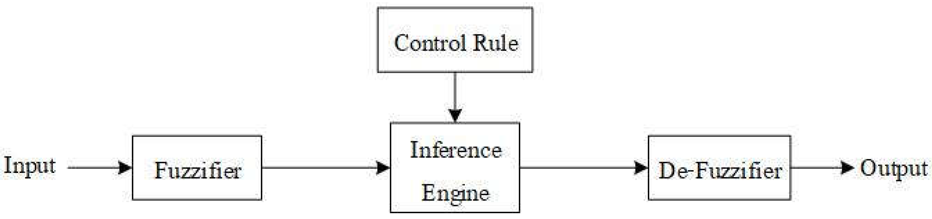
Figure 5.
Membership function of a fuzzy logic controller. [27].
Figure 5.
Membership function of a fuzzy logic controller. [27].
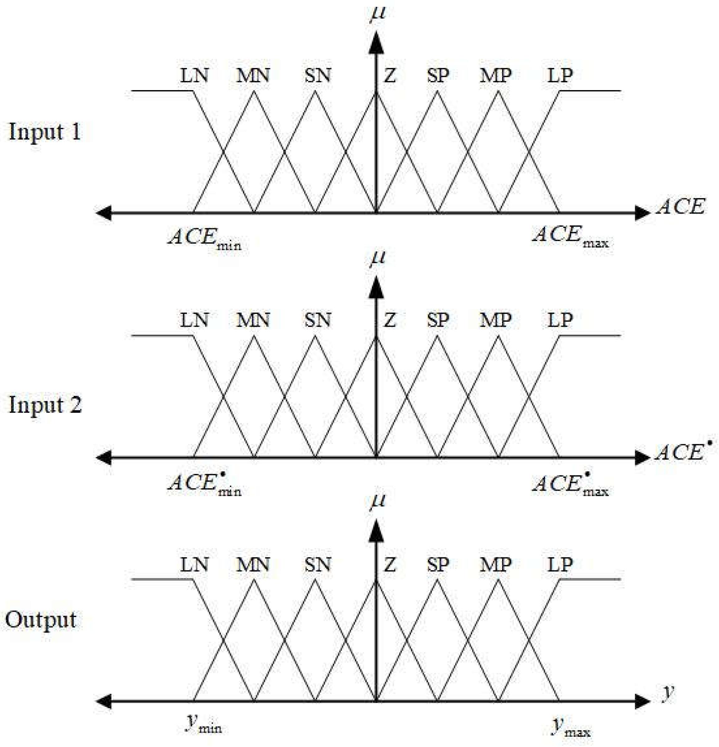
LN: Large Negative; MN: Medium Negative; SN: Small Negative; Z: Zero
SP: Small Positive; MP: Medium Positive; LP: Large Positive.
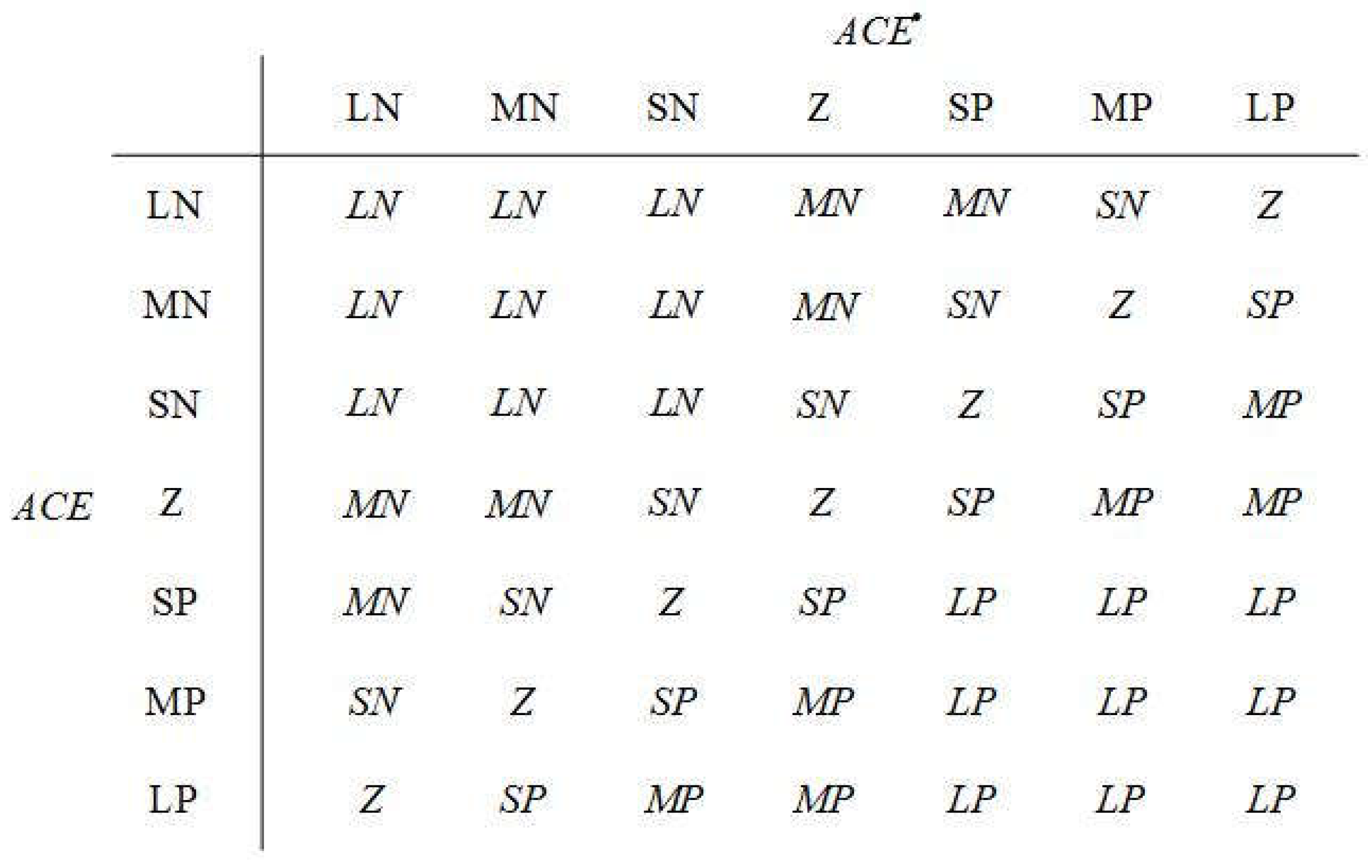
Figure 6.
Regulation guideline of the 2DOF-PID fuzzy logic controller [27].
Figure 6.
Regulation guideline of the 2DOF-PID fuzzy logic controller [27].
The output from the Integral Absolute Error (IAE) operation [35], was selected as the goal for this study. The temporal product of the absolute frequency value and tie-line power fluctuations demonstrate higher performance relative to other objective functions in the Load Frequency Control (LFC) domain [36]:
4. Bee Algorithm
The Bee Algorithm [23] is a technique for identifying optimal values that emulates the nectar foraging habit of bees. It is carried out by bees that are categorized into two types: scout bees and worker bees. To ascertain the solution, presuming it to be a nectar supply, the scout bee's responsibility is to seek a random nectar source within the spectrum of potential solutions. Upon discovering the solution, the scout bee returns to the hive to inform the others. Bees convey information through special dances that signify the quantity of nectar and the direction of the source. Subsequently, the worker bees will collect nectar from the source. The quantity of worker bees fluctuates based on the availability of nectar and the distance. Prior to outlining the operational steps of the swarm technique, the user must set the key parameters associated with the method: they are:
number of repetitions
number of scout bees
quantity of nectar sources with elevated nectar content identified by scout bees
number of nectar sources with the highest nectar content from the selected sources
quantity of scout bees designated to locate nectar sources sources
quantity of scout bees designated to locate nectar sources sources
size of the search range of each scout bee
The Bee Algorithm has the following steps:
Step 1: Assign the number of iterations = 30 and let scout bees locate an initial solution. This solution must be a feasible one, meaning it must fall within a given range and satisfy the requirements.
Step 2: Sort the search results provided by the scout bee in order of highest to lowest value.
Step 3: Select the response that has the best evaluation result.
Step 4: Divide the response into two groups: the first group should have the best responses, and the second group should contain the second-best answers.
Step 5: Specify the search parameters surrounding the responses.
Step 6: Allow worker bees to circle around answers and worker bees to circle around responses.
Step 7: Select the optimal response for each source after analyzing the worker bees' search results in each one.
Step 8: Verify the condition of halting. If the requirement is satisfied, stop searching. If not, raise the count of = + 1 iterations.
Step 9: Allow scout bees to find a different solution.
Step 10: Get a new answer from the scout bees and return to Step 2 again
5. Simulation Test Results
The simulation involves two interconnected areas between hydropower and thermal power plants was conducted using the MATLAB/SIMULATION 2021a program on a machine with a CPU: Core i5-12400F, RAM: 16.0 GB DDR4-3200 and GPU: NVIDIA GeForce RTX 4060. By establishing the controller's scope as and assigning the values = 30, = 30, = 50, and = 40, the parameter values were derived using the swarm approach and are presented in Table 1.
These observations indicate that the identical optimization method and performance objective (IAE) have been employed. The FL2DPID controller surpasses conventional controllers in transient performance parameters, including overshoot, undershoot and stall time. Table 2 presents performance indices associated with different types of controllers. Figure 7, Figure 8 and Figure 9 show comparisons of the simulation results for changes in frequency in areas 1 and 2, as well as changes in the flow of energy over the given time period. The dynamic response analysis indicates a substantial improvement in vibration reduction efficiency through the use of the BA-based FL2DPID controller, resulting in complete vibration mitigation.
Upon examining the performance comparison table, which included PID, 2DOF-PID, fuzzy PID, and FL2DPID controllers, with regard to undershoot, overshoot, and settling time, it was determined that each controller possessed its own advantages and disadvantages. The PID controller had big overshoots in parameters and and it had the biggest undershoots in parameter ,which made the system less stable than other controllers. The 2DOF-PID controller effectively reduces the overshoot in the parameter , however, it exhibits suboptimal performance for the overshoot of the frequency parameters and .
The fuzzy PID controller demonstrates a well-balanced performance. It effectively mitigates undershooting across all parameters. However, it still exhibits a significant overshoot in . This could render the system in Area 2 unreliable. Conversely, the FL2DPID controller exhibits superior performance. It exhibits a minimal undershoot and overshoot across nearly all parameters. This is applicable to and . This demonstrates its capability to regulate the system with optimal stability. The entry time about the FL2DPID controller is comparable to that of the other controllers. However, in certain instances, it still exhibits significant improvement. In order to regulate systems that necessitate exceptional stability amid load fluctuations, the FL2DPID controller is the most effective.
6. Conclusions
This study presented a unique FL2DPID controller as a supplementary controller for load frequency regulation in two interconnected areas between hydropower and thermal power plants. Two energy systems were examined, with one area having heat-generating units and the other containing hydro-generation units. In a nature-inspired, population-based bee algorithm, the integral absolute error (IAE) served as the goal function for optimizing parameters. Our new bee algorithm based FL2DPID controller was evaluated against existing controllers to highlight its advantages. Our new controller had superior performance for an identical thermal system during a 1% step load disturbance (SLP). The system reduced settling times, improved responses for both sub-minimum and over-maximum conditions and had significantly fewer fluctuations in efficiency.
Credit authorship contribution statement
Sitthisak Audomsi: Conceptualization, assessment, enhancement, initial drafting, visualization, verification, software development, resource provision, project supervision, methodology design, formal analysis, data management. Worawat Sa-ngiamvibool: Supervision, investigation, resource management, research execution, funding acquisition, and resource administration.
Declaration of Competing Interest
The authors declare that they have no known competing financial interests or personal relationships that could have appeared to influence the work reported in this paper.
Acknowledgments
This research project was financially supported by Mahasarakham University. The authors express gratitude to the Faculty of Engineering, Mahasarakham University, for providing research facilities. Gratitude is also extended to Associate Professor Supannika Wattana of Mahasarakham University for her insightful comments on the work.
Data availability
The writers lack authorization to disseminate data.
Appendix A
The following criteria were used throughout this investigation [27] : f = 60 Hz, Tr = 10.0 s, Tt = 0.3 s, Tw = 1.0 s, Tg = 0.08 s, Kr = 0.5, Kp = 1.0, Kd = 4.0, Ki = 5.0, H1 = H2 = 5, R1 = R2 = 2.4 Hz/p.u.MW, Ptie,max = 200 MW, Pr1 = 2000 MW, Pr2 = 2000 MW, D1 = D2 = 8.33 10-3 p.u.MW/Hz. When: , ,
References
- Yousef, H. Adaptive fuzzy logic load frequency control of multi-area power system. Int. J. Electr. Power Energy Syst. 2015, 68, 384–395. [Google Scholar] [CrossRef]
- Hu, X.; et al. Adaptive power flow analysis for power system operation based on graph deep learning. Int. J. Electr. Power Energy Syst. 2024, 161, 110166. [Google Scholar] [CrossRef]
- Li, L.; Zhao, W.; Wang, H.; Xu, Z.; Ding, Y. Sand cat swarm optimization based maximum power point tracking technique for photovoltaic system under partial shading conditions. Int. J. Electr. Power Energy Syst. 2024, 161, 110203. [Google Scholar] [CrossRef]
- Qayyum, F.; Jamil, H.; Iqbal, N.; Kim, D.-H. IoT-orchestrated optimal nanogrid energy management: Improving energy trading performance and efficiency via virtual operations. Int. J. Electr. Power Energy Syst. 2024, 155, 109668. [Google Scholar] [CrossRef]
- Arabzadeh, V.; Frank, R. Creating a renewable energy-powered energy system: Extreme scenarios and novel solutions for large-scale renewable power integration. Appl. Energy 2024, 374, 124088. [Google Scholar] [CrossRef]
- Wang, C.; et al. A speed-amplified tri-stable piezoelectric-electromagnetic-triboelectric hybrid energy harvester for low-frequency applications. Nano Energy 2023, 114, 108630. [Google Scholar] [CrossRef]
- Yanine, F.F.; Sauma, E.E. Review of grid-tie micro-generation systems without energy storage: Towards a new approach to sustainable hybrid energy systems linked to energy efficiency. Renew. Sustain. Energy Rev. 2013, 26, 60–95. [Google Scholar] [CrossRef]
- Syrmakesis, A.D.; Alcaraz, C.; Hatziargyriou, N.D. DAR-LFC: A data-driven attack recovery mechanism for Load Frequency Control. Int. J. Crit. Infrastruct. Prot. 2024, 45, 100678. [Google Scholar] [CrossRef]
- Sahoo, A.K.; Sahoo, A.K.; Nayak, S.; Kar, S.K. Load frequency and voltage control of two area interconnected power system using covariance matrix adaptation evolution strategy based Aquila optimization optimized fast fuzzy-fractional order tilt integral derivative controller. e-Prime - Adv. Electr. Eng. Electron. Energy 2024, 8, 100488. [Google Scholar] [CrossRef]
- Khan, I.A.; Mokhlis, H.; Mansor, N.N.; Illias, H.A.; Awalin, L.J.; Wang, L. New trends and future directions in load frequency control and flexible power system: A comprehensive review. Alex. Eng. J. 2023, 71, 263–308. [Google Scholar] [CrossRef]
- Biyya, I.; Oubrahim, Z.; Abbou, A. Frequency and ROCOF estimation under steady-state and dynamic conditions for three-phase grid-connected converters. Electr. Power Syst. Res. 2023, 224, 109723. [Google Scholar] [CrossRef]
- Saha, A.; Bhaskar, M.S.; Almakhles, D.; Elmorshedy, M.F. Optimization of dual-stage controllers in renewable energy sources-based interconnected power systems through refinement of the African Vultures Optimization Algorithm. Ain Shams Eng. J. 2024, 103039. [Google Scholar] [CrossRef]
- An, Z.; Liu, X.; Xiao, G.; Song, G. ; Wang, Tube-based MPC strategy for load frequency control of multi-area interconnected power system with HESS. J. Energy Storage 2024, 99, 113340. [Google Scholar] [CrossRef]
- Jarso, G.C.; Nallamothu, R.B.; Gopal, R.; Jin, G.G. Investigation on steady state performance of hydrodynamic automatic transmission vehicle. Energy Convers. Manag. : X 2024, 23, 100602. [Google Scholar] [CrossRef]
- Pasiopoulou, I.D.; Kontis, E.O.; Papadopoulos, T.A.; Papagiannis, G.K. Derivation of aggregated equivalent models for the steady-state analysis of active distribution networks operated under voltage control schemes. Electr. Power Syst. Res. 2024, 237, 111023. [Google Scholar] [CrossRef]
- Ji, W.; et al. Applications of flywheel energy storage system on load frequency regulation combined with various power generations: A review. Renew. Energy 2024, 223, 119975. [Google Scholar] [CrossRef]
- Yihunie, D.T.; Mugisha, J.Y.T.; Gebru, D.M.; Alemneh, H.T. Optimal control and cost-effectiveness analysis of Fasciola hepatica model. Heliyon 2024, 10, e38540. [Google Scholar] [CrossRef]
- Yao, Y.; et al. Parametric investigation of the effects of variables controlling thermal characteristics during continuous and high-speed cold stamping processes with active cooling structures. Appl. Therm. Eng. 2024, 250, 123488. [Google Scholar] [CrossRef]
- Nishanth, F.P.; Dash, S.K.; Mahapatro, S.R. Critical Study of Type-2 Fuzzy Logic Control from Theory to Applications: A State-of-the-Art Comprehensive Survey. e-Prime - Adv. Electr. Eng. Electron. Energy, 0077. [Google Scholar] [CrossRef]
- Alateeq, M.; Pedrycz, W. Logic-oriented fuzzy neural networks: A survey. Expert Syst. Appl. 2024, 257, 125120. [Google Scholar] [CrossRef]
- Cabral, I.M.; Pereira, J.S.; Ribeiro, J.B. Performance evaluation of PID and Fuzzy Logic controllers for residential ORC-based cogeneration systems. Energy Convers. Manag. : X 2024, 23, 100622. [Google Scholar] [CrossRef]
- Mashaleh, A.S.; Ibrahim, N.F.B.; Alauthman, M.; Almseidin, M.; Gawanmeh, A. IoT Smart Devices Risk Assessment Model Using Fuzzy Logic and PSO. Comput. Mater. Contin. 2024, 78, 2245–2267. [Google Scholar] [CrossRef]
- Zhang, Z.; Fu, Y.; Gao, K.; Pan, Q.; Huang, M. A learning-driven multi-objective cooperative artificial bee colony algorithm for distributed flexible job shop scheduling problems with preventive maintenance and transportation operations. Comput. Ind. Eng. 2024, 196, 110484. [Google Scholar] [CrossRef]
- Zervoudakis, K.; Tsafarakis, S. Fuzzy Self-tuning Bees Algorithm for designing optimal product lines. Appl. Soft Comput. 2024, 167, 112228. [Google Scholar] [CrossRef]
- Nayak, J.R.; Shaw, B.; Sahu, B.K.; Naidu, K.A. Application of optimized adaptive crow search algorithm based two degree of freedom optimal fuzzy PID controller for AGC system. Eng. Sci. Technol. Int. J. 2022, 32, 101061. [Google Scholar] [CrossRef]
- Dalal, S.; Kumar, A.; Lilhore, U.K.; Dahiya, N.; Jaglan, V.; Rani, U. Optimizing cloud service provider selection with firefly-guided fuzzy decision support system for smart cities. Meas. : Sens. 2024, 35, 101294. [Google Scholar] [CrossRef]
- Sa-ngiamvibool, W. Optimal Fuzzy Logic Proportional Integral Derivative Controller Design by Bee Algorithm for Hydro-Thermal System. IEEE Trans. Ind. Inform. 2017, 1–1. [Google Scholar] [CrossRef]
- Meena, V.P.; Singh, V.P.; Guerrero, J.M. Investigation of reciprocal rank method for automatic generation control in two-area interconnected power system. Math. Comput. Simul. 2024, 225, 760–778. [Google Scholar] [CrossRef]
- Zhang, J.; Cheng, C.; Yu, S.; Wu, H.; Gao, M. Sharing hydropower flexibility in interconnected power systems: A case study for the China Southern power grid. Appl. Energy 2021, 288, 116645. [Google Scholar] [CrossRef]
- Liu, P.; Trieb, F. Transformation of the electricity sector with thermal storage power plants and PV – A first conceptual approach. J. Energy Storage 2021, 44, 103444. [Google Scholar] [CrossRef]
- Montazerinejad, H.; Eicker, U. ; Ahmadi, Renewable fuel-powered micro-gas turbine and hydrogen fuel cell systems: Exploring scenarios of technology, control, and operation. Energy Convers. Manag. 2024, 319, 118944. [Google Scholar] [CrossRef]
- Sariki, M.; Shankar, R. Optimal CC-2DOF(PI)-PDF controller for LFC of restructured multi-area power system with IES-based modified HVDC tie-line and electric vehicles. Eng. Sci. Technol. Int. J. 2022, 32, 101058. [Google Scholar] [CrossRef]
- Ahmadnia, M.; Hajipour, A.; Tavakoli, H. Robust variable-order fractional PID-LP fuzzy controller for Automatic Voltage Regulator systems. Appl. Soft Comput. 2024, 167, 112268. [Google Scholar] [CrossRef]
- Alika, R.; Mellouli, E.M.; Tissir, E.H. A modified sliding mode controller based on fuzzy logic to control the longitudinal dynamics of the autonomous vehicle. Results Eng. 2024, 22, 102120. [Google Scholar] [CrossRef]
- Siva Krishna and, V. Gopi Krishna Rao Fractional-order PID controller for blood pressure regulation using genetic algorithm. Biomed. Signal Process. Control 2024, 88, 105564. [Google Scholar] [CrossRef]
- Audomsi, S.; et al. The development of pid controller by chess algorithm. Eng. Access 2024, 10, 46–50. [Google Scholar]
Figure 1.
Interconnected power in two areas [27].
Figure 1.
Interconnected power in two areas [27].
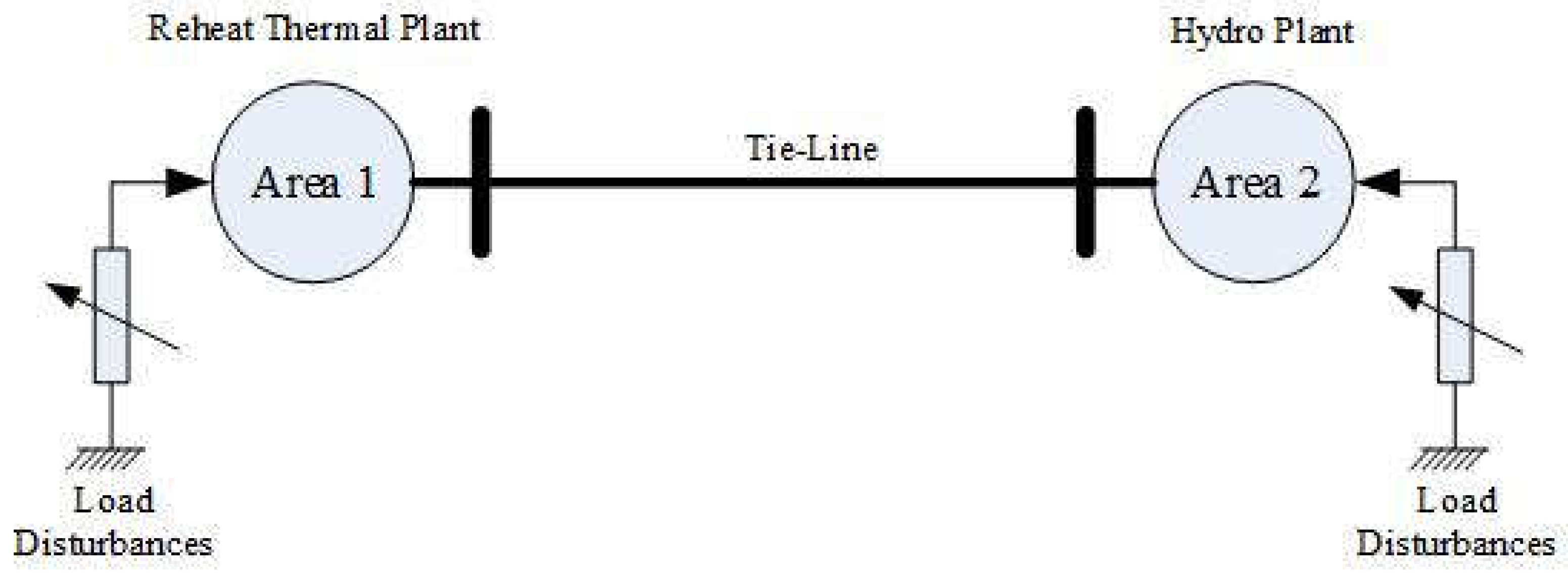
Figure 2.
Model of two interconnected areas between hydropower and thermal power plants [27].
Figure 2.
Model of two interconnected areas between hydropower and thermal power plants [27].
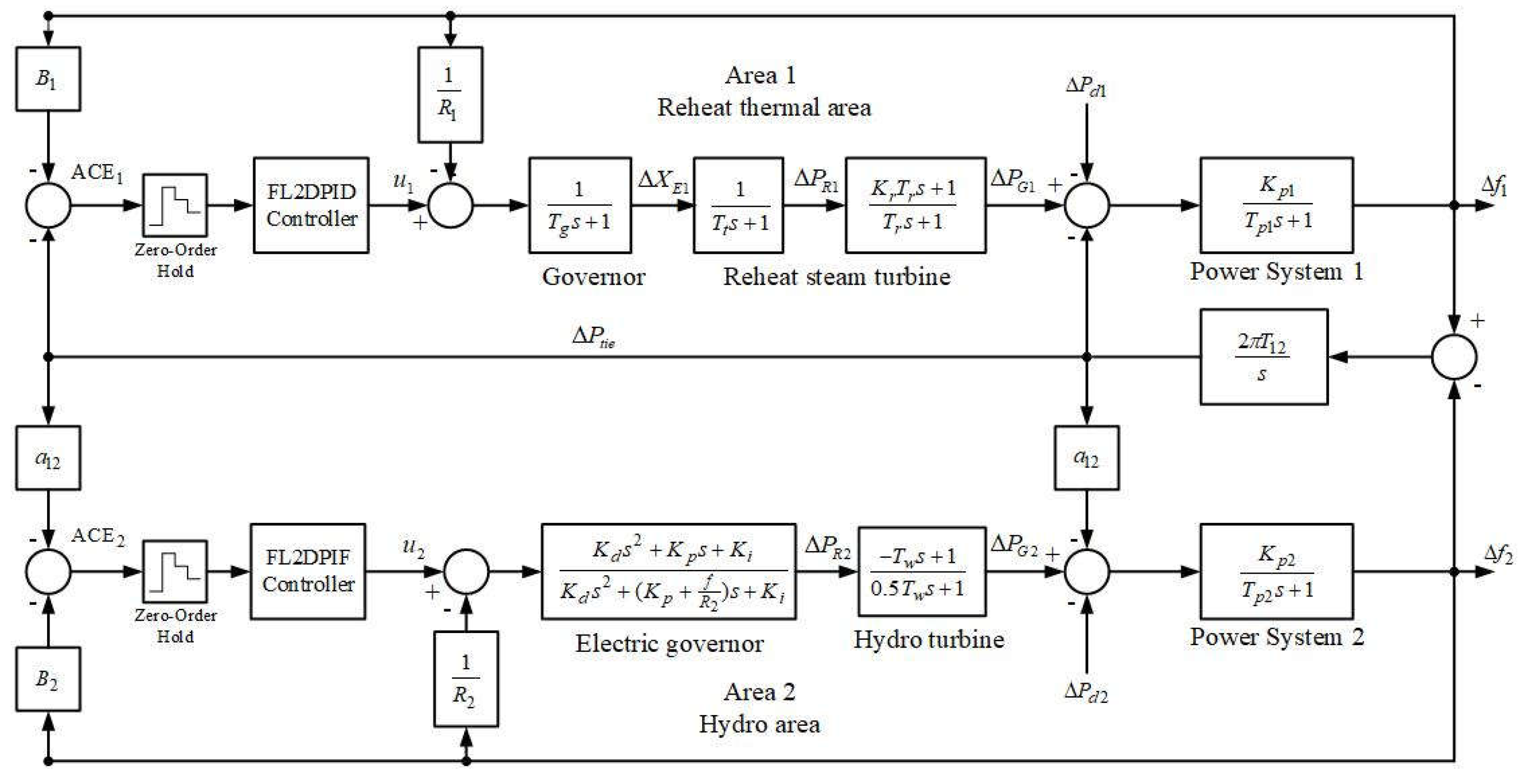
Figure 3.
Block diagram representation of the fuzzy logic 2DOF-PID Controller, adapted from [27].
Figure 3.
Block diagram representation of the fuzzy logic 2DOF-PID Controller, adapted from [27].
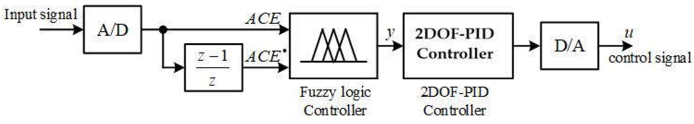
Figure 7.
The frequency diversification of several controller categories in the reheat thermal zone.
Figure 7.
The frequency diversification of several controller categories in the reheat thermal zone.
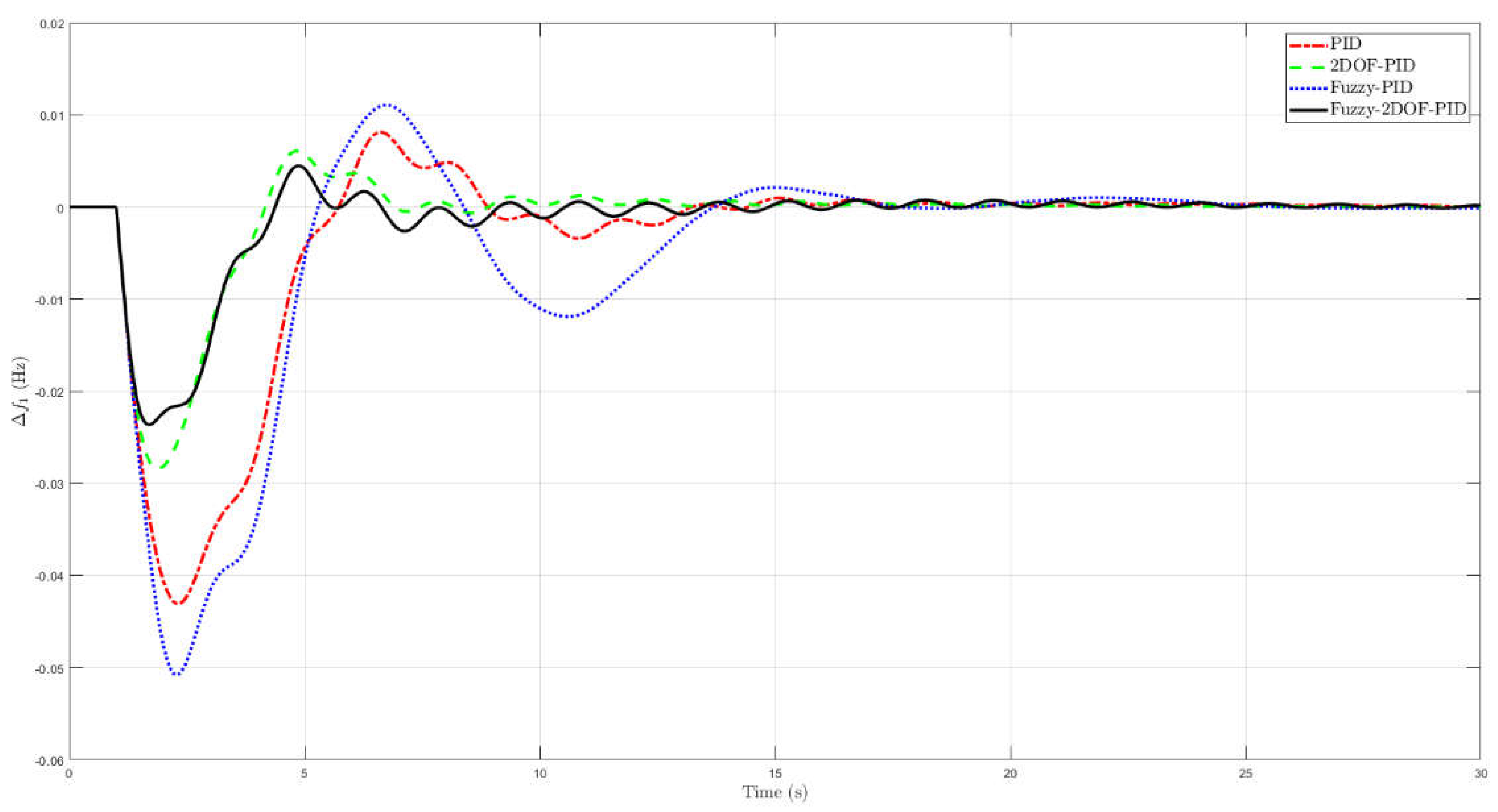
Figure 8.
The frequency diversification of various controller systems in the hydroelectric zone.
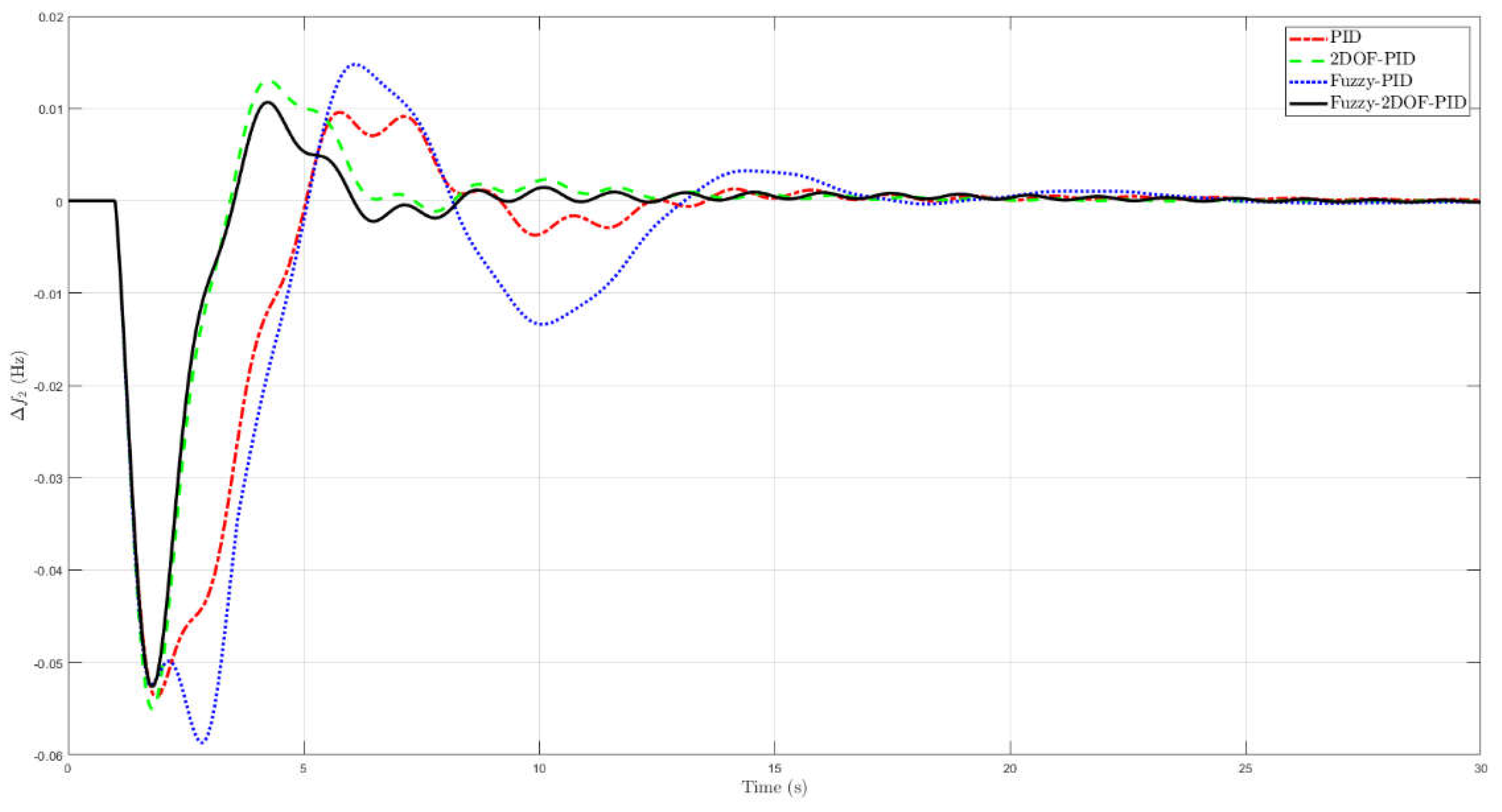
Figure 9.
The frequency diversification of various controller categories for both areas.
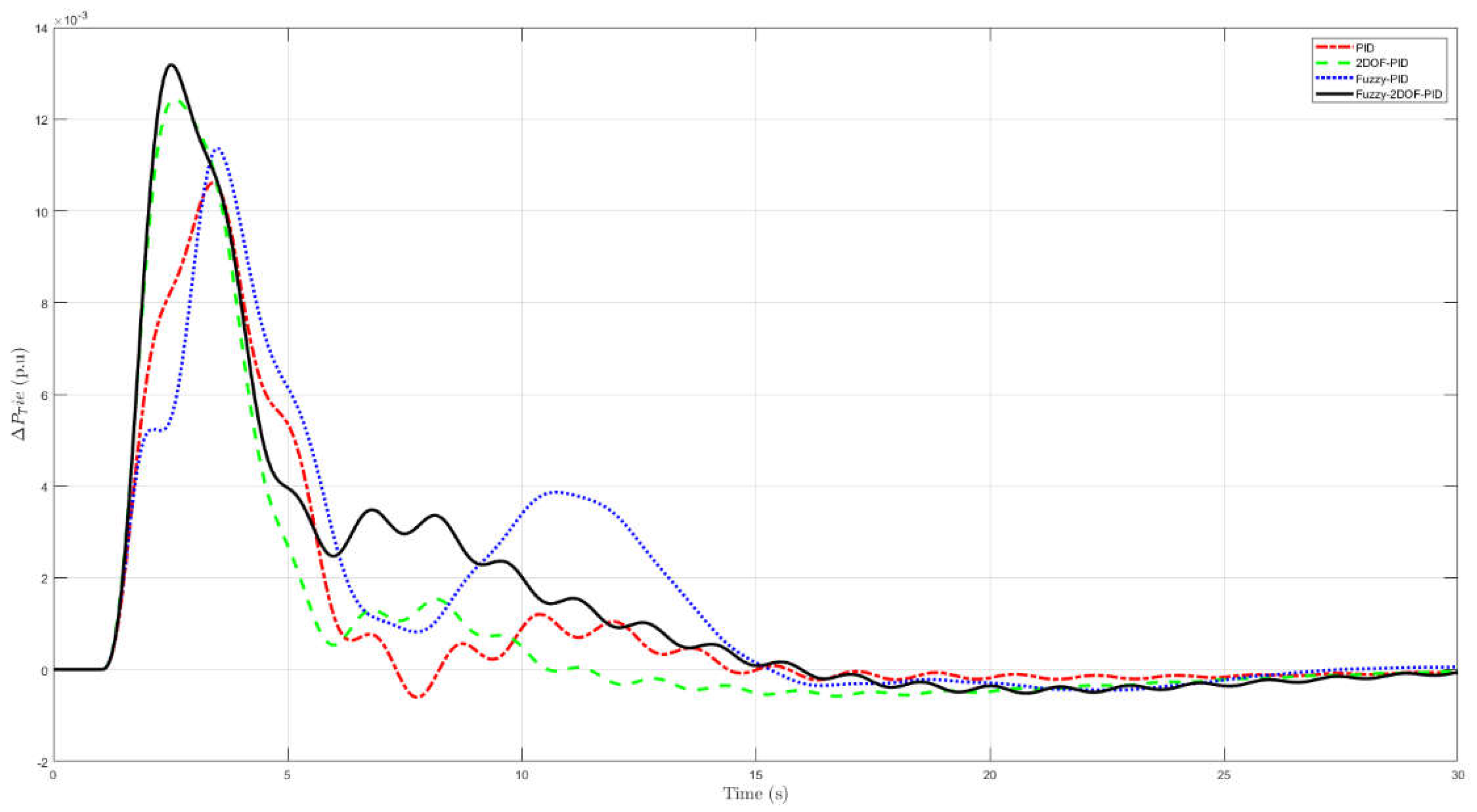

Table 1.
Optimum values of the controller gains.
| Controller Gain |
Reheat Thermal Area | Hydro Area | ||||||
|---|---|---|---|---|---|---|---|---|
| PID | 2DPID | FLPID | FL2DPID | PID | 2DPID | FLPID | FL2DPID | |
| KPW | - | 0.8049 | - | 0.9086 | - | 0.0292 | - | 0.0000 |
| KDW | - | 0.5169 | - | 0.6604 | - | 0.1266 | - | 0.1201 |
| KP | 0.9828 | 0.5856 | 1.0000 | 0.3506 | 0.0231 | 0.2823 | 0.0000 | 0.2503 |
| KI | 0.9981 | 0.2121 | 0.9253 | 0.7175 | 0.1326 | 0.5869 | 0.2363 | 0.2694 |
| KD | 0.5533 | 0.5296 | 0.9095 | 0.4055 | 0.1626 | 0.8937 | 0.4609 | 0.5818 |
| IAE Error | 0.2560 | 0.1504 | 0.3906 | 0.1308 | - | - | - | - |
Table 2.
USH, OSH and Ts of the different controllers.
| Controller | |||||||||
|---|---|---|---|---|---|---|---|---|---|
| Ts | Ts | Ts | |||||||
| PID | 1.3272 | 7.0301 | 5.1330 | 4.8038 | 2.6942 | 5.1366 | 1.8064 | 3.1667 | 5.1500 |
| 2DOF-PID | 2.6401 | 1.2375 | 5.1478 | 1.6920 | 4.0130 | 5.1503 | 7.5531 | 1.6272 | 5.1479 |
| Fuzzy PID | 1.6869 | 7.7342 | 5.1404 | 2.0475 | 8.1416 | 5.1458 | 2.0465 | 5.2067 | 4.4647 |
| FL2DPID | 1.1632 | 2.1964 | 5.1528 | 1.0766 | 2.1820 | 5.1529 | 0.7826 | 2.9880 | 5.1409 |
Disclaimer/Publisher’s Note: The statements, opinions and data contained in all publications are solely those of the individual author(s) and contributor(s) and not of MDPI and/or the editor(s). MDPI and/or the editor(s) disclaim responsibility for any injury to people or property resulting from any ideas, methods, instructions or products referred to in the content. |
© 2025 by the authors. Licensee MDPI, Basel, Switzerland. This article is an open access article distributed under the terms and conditions of the Creative Commons Attribution (CC BY) license (http://creativecommons.org/licenses/by/4.0/).
Copyright: This open access article is published under a Creative Commons CC BY 4.0 license, which permit the free download, distribution, and reuse, provided that the author and preprint are cited in any reuse.


