Submitted:
31 December 2024
Posted:
31 December 2024
You are already at the latest version
Abstract
The field of smart textiles is increasingly growing, producing a variety of new textile materials and fabric functionalities. Yet, significant challenges in areas such as washing, durability, electronic interfacing, and sustainability prevail. To gain widespread adoption, electronically integrated garments will need to rely on robust, fully integrated, and lightweight fiber-based conductive systems. In this paper, we propose the use of Ultralong Carbon Nanotube (UCNT) yarns, as a potential solution to some of the challenges mentioned above. In UCNT, the fibers’ ratio between width and length is orders of magnitude larger than typical carbon nanotube fibers. Amongst other advantages, this enables the manufacturing of stable, workable yarns, made of a network of twisted fibers (tows), which are suitable for integration in fabrics. Our research includes the creation of textile prototype demonstrators integrated with UCNT yarns, which were tested under military-grade textile standards for both mechanical durability and electric functionality. The demonstrators were surveyed before, during and after the various tests, including washability, abrasion, and weathering. The results provide some encouraging results, especially in instances where the UCNT yarns were enhanced by a polymer coating, which provided improved mechanical properties and electrical durability. After washing, tests of the washing residue revealed the presence of UCNT nanofibers, which are banned by the World Health Organization. The paper discusses the possible source of the nanofibers in the washing residue and proposes future improvements to the coating and the testing method. A detailed account of the prototype demonstrators is provided including the weaving pattern, the electronic circuitry, and the component configuration, which enables functionalities of heating, haptic alert, fabric tear detection, touch sensing and moisture detection.
Keywords:
Smart textiles
; e-texiles
; weaving
; nanofibers
; carbon nanotubes
1. Introduction
There is a renewed interest in recent years in the development of smart textiles (aka e-textiles), specifically for the area of wearable garments, for multiple applications of both civil and military uses [1,2,3,4]. This interest is fueled by the miniaturization and prevalence of electronic components, coupled with the development of new flexible material systems. In addition, advancements in wireless networks, cloud computing, energy harvesting, sensors and battery power all contribute to the growing research in this field. Several different conductive yarns are currently being explored for smart textile applications, they differ from one another in their electrical and mechanical properties, production process and cost.
Amongst them, the most typical is the use of copper wires and stainless-steel threads. Despite their optimal electrical properties (typically low resistance of considerably less than 1 ohm/m), these wires are characterized as relatively inflexible, typically high in weight, and due to their mechanical properties usually unsuitable for smooth integration in industrial textile manufacturing processes. Some other notable fibers are Intrinsically Conductive Polymers (ICPs), and extrinsically conductive fibers, which are made of nonconductive thread materials either filled or coated with conductive properties [5]. Typical conductive fillers include, for example: metallic powder, metallic nanowires, or ICPs, which are added into or onto nonconductive commonly used polymer threads. Their disadvantage is that they might suffer from high manufacturing cost, stiffness, brittleness, high weight, low durability and limited signal capacity [6].
Other types of conductive yarns used in recent years are based on carbon. Either in the form of carbon fibers (CF) or in the form of Carbon nanotubes (CNT) fibers, which are tubular fibrous structures composed entirely of graphitic carbon planes. CNTs have the potential mechanical properties to perform better than any commercially available conductive yarn [7]. In comparison to CF, CNT has higher electrical and thermal conductivities and higher strength and flexibility. CNT is thus considered a promising type of conductive yarn for wearable and stretchable smart textiles.
The diameter of CNT can vary, usually from 1-50 nanometers [8]. Most CNTs have lengths in the 1–10 micron range. Because of the short length of these nanotubes, bulk nanotube material is usually produced as a fine black powder which is extremely difficult to apply or use. These CNT powders are grown in a typical Chemical Vapor Deposition (CVD) process and are then harvested [9]. There are substantial drawbacks to using a nano-powder such as a CNT powder for wearable textile applications:
- Nano Powders are a health hazard
- It is not a continuous material
- They are extremely hard to disperse in a solution
- Due to the CNT's short length, their electrical, thermal, and mechanical properties are relatively poor.
Conductive fibers can be integrated into an e-textile by using either knitting or weaving [10]. In addition to the integration of conductive fibers and textiles in wearable garments, they are also being used in applications such as electrostatic dissipation, EMI shielding, signal and power transfer, and as thermal regulation elements. In parallel with the effort to develop new and relevant materials and applications for smart textiles, new standardization protocols are currently proposed, setting the stage for regulations which will further define the requirements and limitations of smart textile products in the future [11]. Therefore, it is of importance for any research in this field to take into consideration the applied nature of smart textiles, and in particular their scenario of use over long periods of time, from inception to end of use.
In our research, Ultra-long Carbon NanoTubes-based smart textiles were developed with the aim of integrating them into uniforms for future soldiers. Smart textile uniforms are mainly intended to provide information about the soldier’s physical condition, especially in operational situations. The goal is to enable the future uniform to collect information relating to a particular wearer, a respective group of wearers and their interaction, and their environmental context. UCNT conductive yarns were integrated into the textile both as the electric infrastructure (i.e., the wiring which interconnects the disparate electronic parts of the system) and as activation sites for different functionalities of sensing and actuation located across the garment. The UCNT yarns that were used in this research were produced by a manufacturer specifically for this project [12]. Previous research shows that UCNT has the potential to be applied as electrodes, and to be integrated as textile-based wearable sensors for cardiac and other medical real-time gauging systems [13].
The research presented in this paper focuses on using UCNT yarns as the principal conductive infrastructure for a wearable smart system, with additional integrated electronic components for added functionalities. This research contributes to the existing knowledge mostly on four aspects: material-wise, the UCNT fibers used here are long and have relatively high electrical conductivity. Detailed description of the patented yarn fabrication process, and characterization, are provided below. Structure-wise, the UCNT is weaved, rather than knitted, into fabric in a standardized textile manufacturing method, a double plain weave structure. Other weaving structures were integrated utilizing a multilayer approach to achieve multiple sensing and actuation capabilities. A detailed account of the weaving process used here is provided. Application-wise, several textile demonstrators are described in detail. Finally, durability-wise, the results of standard abrasion, washability and durability tests, and some respective assessments, are provided.
The goal of the textile demonstrators was to show relevant properties of UCNT for smart textile; in particular: high conductivity, fast heating and cooling rate, high durability and chemical stability. Due to its novelty, there are some unknowns about UCNT and its specific suitability for wearable smart textiles [14,15]. The assumption was that by defining a specific scenario of use for the soldier uniform, and through a series of tests that adhere to strict textile standardization specifications, we would be able to better assess the suitability of the material for this purpose and point to its potential appropriateness and the efforts needed for future research and development of UCNT for smart wearable applications.
2. Materials and Methods
The scenario of the future soldier provided the rationale for developing our work method, which was based on producing a series of textile demonstrators. The demonstrators were comprised of a woven fabric, which is normally the type of textile used in uniforms. Additionally, in comparison to other textile fabrication methods, such as knitting, weaving was identified as better suited for the mechanical attributes of UCNT yarns, considering properties such as yarn curvature requirement, yarn elongation and strength [16]. The weaving pattern consisted of a recurring grid of functional “pixels”, measuring 4 x 5 cm, in which UCNT yarn was integrated. Each pixel was designed to have a specific sensing or actuation function (and could contain multiple concurrent functionalities). Pixel functionality was defined according to the location of each pixel in relation to the wearer’s body, the weaving pattern (circuitry configuration), and the microcontroller code activating the system.
The demonstrators included a rigid-to-flexible multilayer construction which enabled to connect of necessary rigid electronic components (such as, e.g., circuit boards and buzzers) to the conducting UCNT yarns. The flexible layer which was added to the fabric after its production, was made of Pyralux® (DuPont), a clad of laminated composites made of a flexible copper layer with a bonding film of dielectric materials made with Teflon® and Kapton® (polyimide) films [17]. Special connecting points, formed on the Pyralux® substrate, allow for manually sewing the UCNT yarns directly onto the substrate, creating a reliable and consistent electrical connection between the fabric-integrated UCNT yarns and rigid electronics.
The sensing and actuation functionalities of the prototype demonstrators included tear detection, resistive touch, wetness detection, and pressure sensing. Initial actuation capability included heating and haptic alert (by integrating an off-the-shelf electronic buzzer). Future demonstrators may further include functionalities such as pH and temperature sensing.
The communication and data transfer were based on multiple “hubs” consisting of a rigid printed circuit board (PCB), based on Arduino Nano microcontroller unit (MCU) and NanoRF v1.5 Breakout Board for radio frequency (RF) wireless communication. The smart garment is designed to store information locally (vs. cloud) and transmit data via RF for privacy and security reasons, analytics take place remotely, away from the wearable garment. Some of the rigid components were designed to be removable, which facilitates future interchangeability, software updates and reconfiguration which typically needs to be done away from the garment. Furthermore, it will allow for component removal before washing if needed.
The UCNT used in this research is a continuous CNT material in the form of fibers that can also be manufactured as mats [18] The core technology of the production process for these nanofibers is based on a novel patented process [19,20]. The process is a continuous gas phase catalytic reaction via Floating Catalyst Chemical Vapor Deposition (FC-CVD) between a floating catalyst and a hydrocarbon source. The result of this catalytic reaction is a dense cloud of very long CNTs (in the range of 1 mm and longer) that create a continuous network of UCNT. This UCNT cloud can be drawn out of the reactor and spun on a drum to create a non-woven mat or spun on a bobbin to create UCNT yarns. The wire reactor operated by the manufacturer generates continuous UCNT yarns with a diameter of 50-200 microns (see Figure 1).
This process of producing UCNT yarns utilizes inexpensive precursors, which can lead to a relatively inexpensive final product in a fully industrialized process. This technology enables the production of UCNTs with material properties that reach extremely high electrical, thermal, and mechanical properties (17), which are relevant for applications of e-textile and smart clothing, such as:
- High electrical conductivity – values of up to 1.3 × 10⁶ S/m. For comparison, Copper (Cu), which is one of the most abundant and commonly used conducting metal, has a conductivity value of 5.9 × 10⁷ S/m,
- Low density – UCNT yarns have a typical density of 0.25-0.6 g cm-3. In comparison, copper has density of 8.96 g cm–3.
- High chemical and thermal stability – the yarns are stable up to 400°C and can easily withstand harsh chemical environments, including acids and other oxidizers
- High mechanical strength – single yarns show mechanical strength of 0.2 up to 1.2 N/tex depending on the manufacturing configuration. For reference, cotton yarns’ tenacity is 0.17 N/tex, and high-tenacity nylon yarns can reach up to 0.68 N/tex [21].
Despite showing promise in wire applications, UCNT have one clear disadvantage with regards to the possibility to achieve good electrical contact with copper wires, which are abundant in all electronic devices. Copper to copper contact is typically implemented by soldering. However, connection of UCNT fibers to copper usually results in high resistance and limited stability, therefore, electrical signal transfer is inefficient. Note that the electron transport mechanism in UCNT is different from that of metal-based wires. This problem can be partly overcome by the deposition or soldering of metal around the edges of UCNT fibers, such as Ti, Cr or Fe. Another solution is to deposit amorphous carbon between the UCNTs that will effectively solder its edges, without compromising its mechanical or electrical performance [22]. In this project soldering was accompanied by forming mechanical connections, based on sewing between flexible and semi-rigid interfaces. In the future this solution will need to be further developed since it is a labor-intensive manual process.
2.1. UCNT Consisting of 6 Tows
The produced UCNT fibers have sub-mm estimated length, at an average diameter of . The average measured resistance per unit length of the single tow UCNT bundles is and the Tenacity is 0.2 N/tex. Considering this diameter, and assuming fibers with a circular cross-section, the above average value of resistance translates to an electrical conductivity as follows:
For the 6 tow UCNT, coated with PVDF, the respective value is (see Table 1 below)
Reference [23] provides a review of available CNT yarns produced by various spinning methods. Note, in particular, that the above calculated conductivity values of the UCNT are high, compared to the respective values in Table 1 in [23], which span the range . Initial experiments with a single CNT filament showed its tenacity is insufficient for processability due to the fiber’s fragility under tension. Therefore, a twisting unit was engineered to allow the combination of filaments arranged in a tow formation, to increase the mechanical integrity of the yarn. Each tow is composed of an untwisted bundle of continuous filaments, that are formed into a yarn by a winding process, where several tows are wound together. In this research each yarn is composed of 6 tows of UCNT filaments, showing higher strength and better robustness.
The 6-tow fiber’s initial properties were further enhanced using a simple post-processing technique of coating with polyvinyl fluoride (PVDF, 400K, Sigma-Aldrich) for reasons of safety, processability, robustness and abrasion resistance. PVDF is a highly non-reactive thermoplastic fluoropolymer, with low density (1.78 g/cm3) and resistance to solvents, acids, and hydrocarbons, and was found to be suitable for this application by previous research work [24] . Table 1 Coating Types - 61-V1E shows the entire range of coating materials that were initially considered and tested. Of them, PVDF 400K showed the most promising performance in terms of workability and compatibility with the CNT yarn. 400K refers to the average weight of the polymer chains; higher molecular weight increases toughness and strength, enhances heat resistance, and impacts viscosity and processing. The impregnation with thermosetting resins was aimed to reduce the yarn’s resistance and further increase its strength (see Table 2).
2.2. PVDF Coating Application
The UCNT yarns are coated with PVDF, using the setup described below (see Figure 2). In addition to the reasons mentioned above, PVDF was chosen due to its low cost and ease of application. During initial testing it was clear that many different parameters affect the coating quality, such as polymer and solvent type, polymer concentration, drying temperature, mechanical set-up, bath residence time and tow twisting. Therefore, although full uniform coverage of the CNT surface was achieved (see Figure 3), coating optimization should be further continued. For the test samples provided, UCNT yarns were coated with a single (Figure 4a) and a double layer of PVDF (Figure 4b). Scanning Electron Microscopy (SEM) images of the UCNT yarn cross-section show that double coating provides a more substantial overall coating, with non-uniform thickness along the circumference of the yarn (Figure 4b). Weaved test samples were integrated with both yarn types, of single and double coating, and tested comparatively. Although reducing yarn’s overall resistance, the PVDF coating provides some insulation to the outer layer of the fiber. Therefore, yarn edges that needed to be connected to the electronic testing device with a reliable low-resistance connection were exposed using a solvent that locally removed the coating from the yarn edges [25]. The exposed yarn tips were used to measure the electrical properties of specimens before and after the mechanical impact tests. The ability to entirely remove the coating upon choice is important for future potential applications of the project, which will be further discussed.
Figure 2 shows a SEM image enlargement x1500, of the PVDF coating penetrating into the outer circumference of the UCNT 6 tow yarn, with instances of deeper penetration in between filaments. Empty gaps can be detected in the inner core of the yarn, especially where the different tows are intertwined (See also Figure ). Complete penetration of the coating to the entire core of the yarn will likely improve yarn properties, in line with previous research [24] and with the results shown in Table 2.
2.3. Weaving Structure
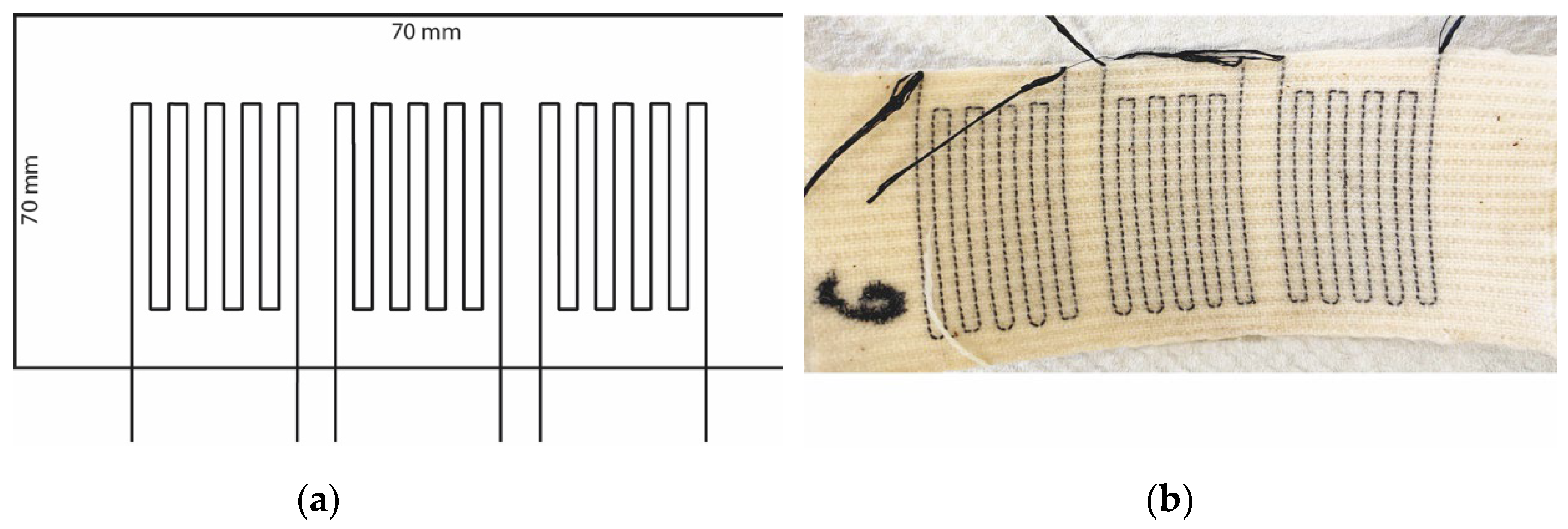
The demonstrators and the test samples were weaved on an ARM manual loom. The basic fabric is constructed from two weaved interconnected layers, creating a double-face fabric. The front face contains the conductive fiber, and is the active layer, the back face is a non-active face functioning as an insulating layer between the wearer’s body and the outer layer fabric. The layers are interconnected by an interlacing stitch occurring in each repeat, which contains 4 thread counts on the weft and 12 thread counts on the warp. Both weft and warp threads are of cotton 20/2 ne (ne=English cotton count signifying 2 ply yarn with 20 yarn count per ply). In every 1 cm fabric width the weft thread count is 14. The textile is weaved in a double plain weave structure. Plain weave is a basic geometric structure where the first weft yarn is passing below the first warp yarn and then above the second warp yarn and continues in an alternating manner. The second weft yarn starts in the opposite direction: above the first warp yarn and below the second one and continues to alternate. On each repeat there are 12 warp yarns and 4 weft yarns, so that each layer receives 6 warp yarns and 2 weft yarns. The first and third weft yarns construct the upper layer and the second and fourth yarns construct the bottom layer. On its way, the fourth yarn grabs the first warp yarn of the upper layer, creating an interlacing stitch connecting between the two layers. This sequence repeats throughout the fabric (Figure 6).
A conductive UCNT coated 6-tow yarn is integrated together with each fourth weft yarn of the repeat sequence. The conductive yarn does not go through the entire width of the fabric, like the rest of the weft yarns, but is integrated in designated positions planned in advance (Figure 7). The UCNT yarn can do one of two things: it can either join the weft yarn, in parallel to the width of the fabric, or it can join one of the warp yarns at 90° (within the plain of the fabric), in the weft direction, in parallel to the length of the fabric (Figure 7). The integration of the conductive yarns is administered during the weaving process continuously, as the fabric is forming, without obstructing the progression of the manufacturing process. Under the requirement of continuous production, the conductive yarn cannot be weaved in the opposite direction of the manufactured fabric, meaning its pattern needs to take into consideration the progression of manufacturing and the directionality of the weft and warp yarns.
Additional to the double-layer weave described above, a triple-layer weave was developed, creating a double-face fabric with three interconnected layers, all in a plain weave structure. The front face contains the conductive fiber, and is an active layer, the middle layer is a non-active insulating layer, and the back face contains conductive fiber, and is an active layer interacting with the wearer’s skin. On each repeat there is a total of 12 warp yarns and 6 weft yarns, therefore each layer receives 4 warp yarns and 2 weft yarns. The first and fourth weft yarns construct the upper layer, the third and sixth yarns construct the bottom layer, and the second and fifth weft yarns construct the middle layer. On its way, the fifth yarn grabs the first warp yarn of the upper layer and the fourth warp yarn of the bottom layer, creating interlacing stitches connecting between the three layers. This sequence repeats throughout the fabric. (See Figure 8).
A conductive UCNT coated 6-tow yarn is integrated together with the six weft yarns of the repeat. It does not go through the entire width on the fabric like the rest of the weft yarns but is integrated in designated areas which were planned beforehand, as explained previously.
2.4. Multi-Layer Conductive Fabric
The abovementioned weaved fabric structures, a double and triple weave, integrated with a coated non-insulated conductive UCNT yarn can be assembled into multiple configurations for a variety of smart applications (see Figure 10). Multiple-layer woven structures for electronic textiles can solve some of the challenges associated with single-layer fabrics [26]. In multi-layer fabrics, single yarns can be moved between layers, away or towards each other, according to the desired configuration. In addition, an intermediate insulating layer can be woven in the fabric, providing the necessary division between non-insulated sensing/conductive elements, creating different usable faces to the fabric which can be positioned towards or away from the body in the case of wearable applications. Double, triple, and multiple-layer woven structures can be produced on readily available weaving machines with very little modifications [27].
Another option to incorporate electronic circuit elements in woven textiles is by integrating a pocket by splitting the fabric into a double-layer structure (Figure 11). This method allows for integration of electronic circuitry, in this example a layer of piezo-resistive non-woven off-the-shelve mat (EeonTexTM). Pockets can be integrated along the width and length of the fabric and their edges can be kept either open or closed.
2.5. Printed Circuit Board (PCB)
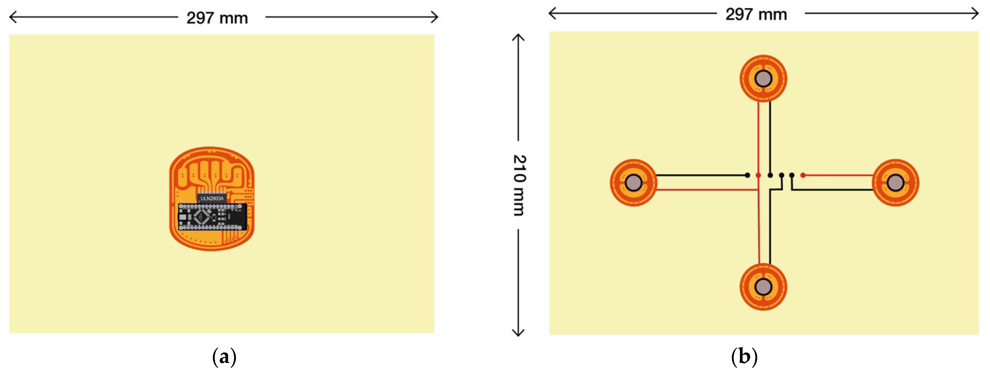
A Printed Circuit board (PCB) was engraved on a Pyralux® (DuPont) tape. The base material is a Kapton® film with a 70 µm single-sided copper layer on the top, with a maximum thickness of 150 µm. 2 mm diameter holes were created, positioned according to the design of the system (Figure a). The holes enable a connection point between the fabric and the flexible substrate containing the circuit board. This is an essential connection point that would need to be further tested in future models for durability and stability. In this current prototype the UCNT yarn was sewn tightly into the surface with a manual stitch which provided the respective eletrical signal (Figure 12b).
2.6. Standard Textile Testing
All the standard textile tests were conducted on weaved fabric samples containing the UCNT, without the flexible PCB. Abrasion tests were divided into two types of tests, raising the intensity of the abrasive counterpart material, wool fabric in the first test and abrasive paper in the second. Abrasion resistance tests were based on EN-ISO 12947-3-d for test 1 and DIN 5363-2 for test 2, reflecting the two counterpart materials respectively. The tests were conducted using a Martindale machine with a 12 kPa weight. The woven samples measured 70 mm2 and contain a “pixel” pattern integrated with UCNT yarn coated with either a single or double layers of PVDF.
Washability tests were divided into industrial and domestic according to EN-ISO 105-C06 and EN-ISO 105-C12 standards. Samples measuring 100x40 mm2 contained three consecutive pixels integrated with UCNT yarn coated with either a single or double layer of PVDF. The domestic test is comprised of 5 washing cycles at 60 °C for 45 minutes with 50 steel beads. The industrial test is comprised of a single wash at 75 °C for 60 minutes with 25 steel beads. Residual washing water was then filtered with an 800 nm nuclear pore filter followed by a 200 nm filter. The filter was analyzed by SEM inspection to search for CNT residual. The following samples were tested: 4 samples of cotton only as control, 4 samples of cotton and PVDF, 4 samples of cotton with CNT coated with PVDF, wash solution without fabric, and demineralized water. In order to obtain a solution which can be filtered more easily, 10 ml of each wash liquor was diluted in a measuring flask with demineralized water to a total volume of 50 ml (dilution 1:5). Each measuring flask was rinsed with a small amount of water and the solutions thus obtained were passed through the corresponding filter. Filters were dried in a drying oven at a temperature of 50 °C and subjected to a SEM analysis.
In order to identify the source of fibrous structures a semiquantitative analysis for the presence of the carbon elements, oxygen and fluorine, was performed on several fibers using energy-dispersive X-ray spectroscopy (EDX). Apart from the actual wash trials, blanks were run to ensure that any fiber material found could be clearly traced either to the CNT material or to another source.
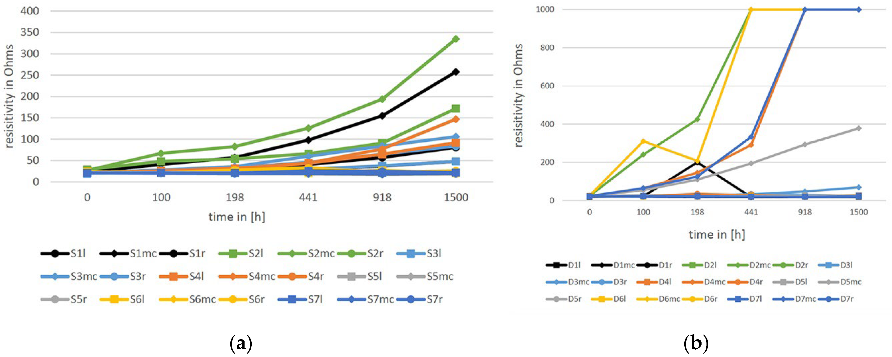
Artificial weathering tests were conducted according to EN- ISO 105-B10-A standard. Samples provided were of 140x150 mm2 and contained three 6-towed UCNT yarns. Samples were taken out from the designated weathering chamber at incremental times and were measured for their visual appearance and resistivity.
3. Results
3.1. Demonstrator
The working prototype operates in two ways, both as a sensor and actuator, containing a field of 4 pixels; however, the intention is to increase the number of pixels in the future, so that the fabric is eventually entirely integrated with active units.
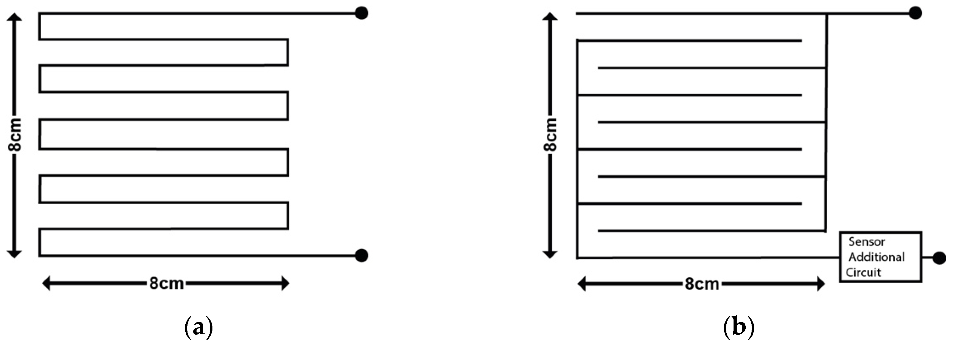
The two patterns of pixel electrodes are: (1) A digital switch electrode, comprised of a continuous UCNT tow (Figure a), and (2) an analog resistive touch electrode comprised of two separate UCNT tows that are weaved in parallel (Figure b). The first type of electrode serves as a rupture detector, and as a heating element. When the yarn is interrupted along its continuum, the electronic signal is detected by the system and interpreted as rupture. As a heating element, the continuous yarn is heated by a low current which is controlled with a thermostat in the range of 24-60 ℃.
Figure 13.
(a) Rupture/Disconnection Electrode; (b) Resistive Touch/Wetness Electrode.
UCNT fibers coated with PVDF respond well to heat, and cool down relatively quickly after heating, reaching original temperature after 1 to 2 minutes. In a preliminary study, different woven configurations were tested, with a goal to achieve a homogenous heat distribution on the fabric surface, tested using a heat camera (Pocket Thermographic Camera Flir C2). Heating temperatures were determined between 24-60 °C, which represents a relevant range for the required functionality of human activity in low temperatures. The yarn resistance was measured to be 81.82-82.76 Ω. Thus, A relatively low current (0.061-0.1 A) was sufficient to raise the yarn temperature in the range indicated above. The tests included using different levels of voltage (3-9 V) and changing the distances between the yarns, resulting in pixels of varying sizes and configurations. The chosen configuration is model 3 (Figure 14).
Analog resistive touch pixels in the demonstrators operate as touch and wetness sensors, initially integrated as binary sensors indicating the presence of touch and/or wetness. When the two separated yarns in the pixel are bridged through touch or wetness, the effective resistance is changes, and a respective electrical signal is detected by the system. When the fabric is wet, charged particles (ions) in the water carry some electrical current through the fabric. Human touch activates the circuit by creating a parallel current path through the body. The current is low enough (~0.043 Ampere) to be undetected by the person. Resistive pixels can also be integrated with EeonTexTM as a double layer weaved structure (Figure 15). EeonTexTM sheet is a pressure-sensitive conductive nonwoven microfiber textile made using a proprietary coating technology, based on doped polypyrrole (PPY), an inherently conducting polymer. EeonTexTM is piezo-resistive and is commonly used in dynamic sensors to map and measure pressure, bend, angle stretch and torsion (surface resistivity tunable from 8-105 Ω/sq). In this configuration the changing resistivity of the EeonTexTM is registered by the adjacent UCNT yarns.
The pixels are arranged as a network grid of active cells, which can operate both as receivers and transmitters of data. Figure shows an overview of the principal wireless communication of a proposed scenario, in which certain cells receive information and activate other cells accordingly. The activated cells can be situated on the same garment or can be located on a different fabric segment (possibly on a different person) providing infrastructure for group communication. In parallel, any cross communication can be simultaneously sent to a main computer for display, registration and/or analysis. The scenario presented in Figure contains Node 0, which is the display monitor, Node 1 is connected to a pixel array of resistive touch sensors (which function as transmitters), Node 2 is a receiving textile integrated with a haptic navigation system which activates 4 vibration motors arranged like a compass, indicating to the wearer the directions of left, right, front, and back (See Figure ). The resistive touch pixels which are arranged in a grid layout, remotely operate the motors according to their position in the grid. Touching each one of the four resistive touch pixels transmits a signal to both the master node, and to the haptic navigation receiver. This wireless communication network is designed to eventually allow for multiple communication systems, on body or between wearers.
Figure 16.
Wireless communication network (2.4GHz RF transceiver Module, Operating Voltage: 3.3V, Nominal current: 50mA, Range: 50 – 200 feet, Operating current: 250mA (maximum), Communication Protocol: SPI).
Figure 16.
Wireless communication network (2.4GHz RF transceiver Module, Operating Voltage: 3.3V, Nominal current: 50mA, Range: 50 – 200 feet, Operating current: 250mA (maximum), Communication Protocol: SPI).
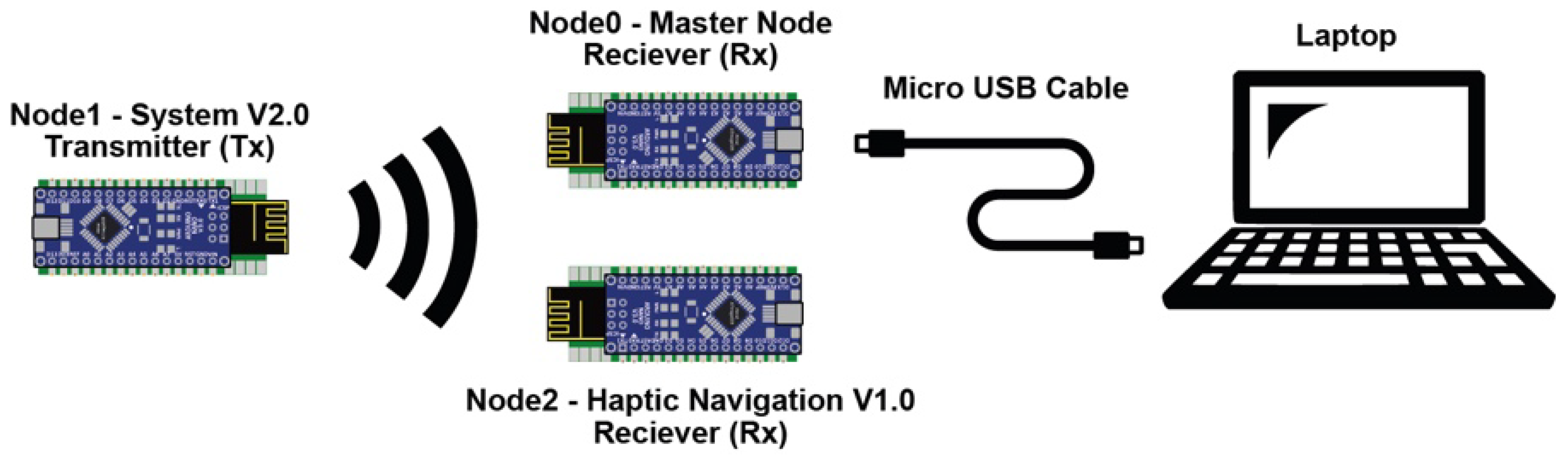
Figure 17.
Haptic Navigation System (a) Top view; (b) Bottom view.
3.2. Textile Testing Results
Textile standardization tests are the backbone of industrial production and are required for integration in any real-life application. Standardization will promote the acceptance of new technology. Therefore, in parallel to developing functionalities and application scenarios via the prototype demonstrator, we produced identical textile samples which contained all the configurations mentioned above for the purpose of conducting an ensemble of mechanical and electronic tests. The standardization of smart textiles or smart textile products and systems is not straightforward because it involves an overlap between the standardization of the “traditional” textile product and the standardization of the additional intrinsic functional properties of the smart product [11]. In addition, due to the integration of nanomaterials, standardization tests also include the World Health Organization (WHO) standardization for the integration of nanomaterials.
In order to test electronic functionality, we followed the “traditional” textile standardization tests and added a component of resistivity measurement before and after the test cycles. We also conducted washing water filtration tests and SEM inspection analyses to detect residue of nanoparticles. The WHO definition of dangerous fibers in terms of their dimensions is a length of > 5 μm, diameter < 3 nm and length-to-diameter ratio of > 3:1.
3.3. Abrasion Resistance I
The results of the abrasion resistance tests using wool as counterpart (EN-ISO 12947-3-d) were conducted until UCNT fibers were visually pulverized (See Figure 18). Resistivity remained steady until pulverization. Single coated fibers pulverized after 20,000-40,000 cycles and the double coated fibers withstood 55,000 cycles. On average, the target point with standard uniform garments is between 30,000-40,000 cycles, which situates the samples’ performance within the required range, especially for the double-coated samples (see Table 3).
3.4. Abrasion Resistance II
The results of the abrasion resistance tests using sandpaper as counterpart (DIN 5363-2) (See Figure 19) show single coated fibers pulverized after 300-500 cycles. Resistivity remained steady until pulverization. Double coated fibers produced similar results. While the double coating improved the fiber protection against the wool fabric, it did not offer any advantage against the sandpaper abrasion (see Table 4).
3.5. Washability
Washability test results (EN-ISO 105-C06 and EN-ISO 105-C12) showed similar fabric deformation results for single and double coated samples (See Figure, example of a sample after washing). Both single and double coated fibers showed a 20 Ω increase in resistance after the washing cycle, a 25% drop in the conductivity. For the domestic wash, however, double coating showed improved durability: whereas single-coated fibers showed a 15 % increase in resistivity, double-coated fibers showed only a 9.27% change (Table 5).
The residual washing water was filtered in a double process, as previously described, and analyzed by SEM in search for CNT residuals. The filtration provided evidence of residual structures, most likely originating from the UCNT fibers, with a length to width ration of 5 µm to 200 nm.
Figure 20.
(a) Sample for Washability test under EN- ISO 105-C06 Commercial Laundry and EN- ISO 105-C12 Industrial Laundry; (b) Image of the sample after testing.
Figure 20.
(a) Sample for Washability test under EN- ISO 105-C06 Commercial Laundry and EN- ISO 105-C12 Industrial Laundry; (b) Image of the sample after testing.
3.6. Artificial Weathering
Weathering test results (following EN- ISO 105-B10-A, see sample configuration (Figure ) indicate that over time, the double coated fibers gave better protection to the fibers than the single coated ones. However, there is a relative high inconsistency in the tests, with a high percentage of specimens failing the process (Figure ).
Figure 21.
Sample of Artificial weathering test under EN- ISO 105-B10-A.
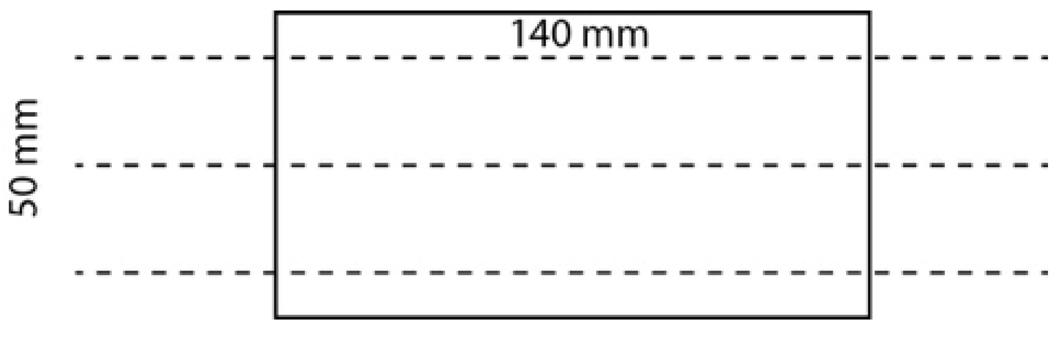
Figure 22.
Artificial Weathering CNT yarns (a) Single coated; (b) Double coated.
3.7. Further Procedures
Testing of wash liquors for the presence of CNTs with the WHO fiber structure (See Figure ) was conducted by examination of the residual wash liquors to determine whether the mechanical action of the washing process had released particles from the CNT yarn which are considered as bio-persistent and fall under the definition of the WHO fibers in terms of their dimension. The tests involved SEM scans which followed VDI 3866 Paper 5, the standards of the Association of German Engineers, relating to scanning electron microscopy methods for determination of nano-scale particles in technical products.
Figure 23.
Scheme of the residue test method for qualitative hazardous WHO nano particles.
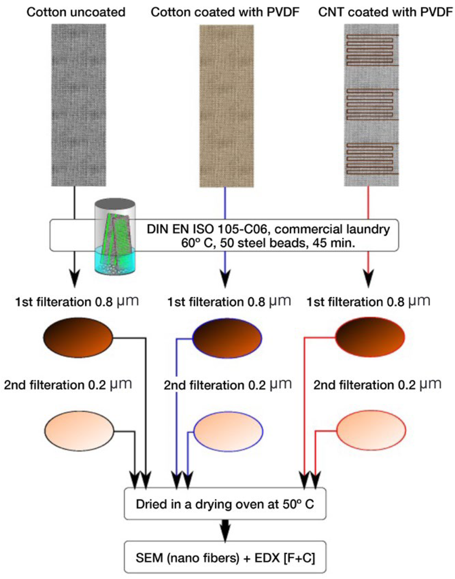
The 800 nm nuclear pore filters, used for collecting residue, were covered densely making it impossible to find and identify CNT structures. The filter cake was so thick that the filter pores are no longer visible. 200 nm nuclear pore filters, which were used subsequently, were densely covered with residue, however empty spaces on the filter were detected, enabling to visually examine the filter material. Fibrous structures were found, with comparably little search effort (see Figure ).
Figure 24.
is an overview picture of 200 nm nuclear pore filter with examples of fibrous structures (highlighted in circles).
Figure 24.
is an overview picture of 200 nm nuclear pore filter with examples of fibrous structures (highlighted in circles).
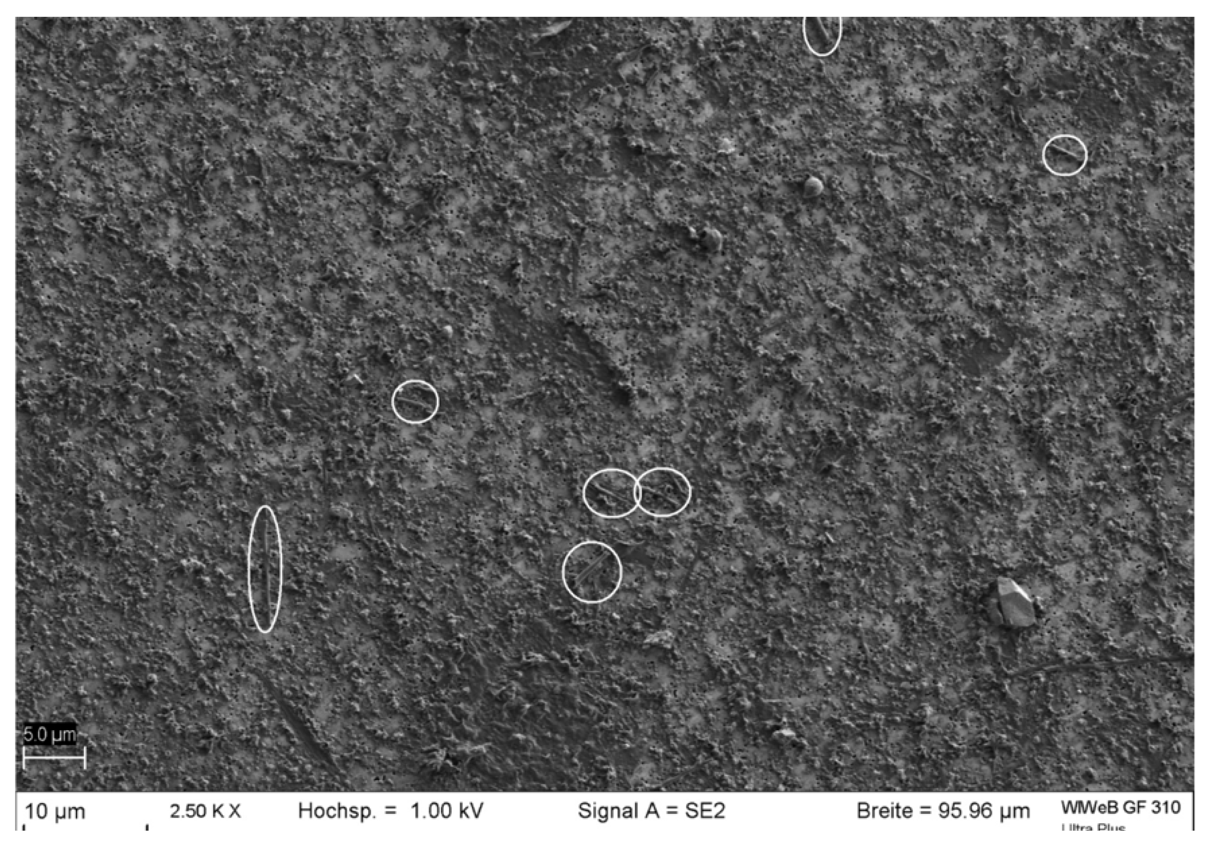
The structures have a mean diameter of around 270 nm, but the diameters vary in a range from around 200 nm to 450 nm. A considerable proportion of these structures have a length of more than 5 μm (Figure 25). Therefore, these structures fall under the definition of the WHO fibers in terms of their dimensions. Overall, it is interesting to note the very smooth surface of the structures is markedly different from natural cotton fibers.
Figure 26 shows a fiber structure from a sample that possesses the geometry of the WHO dimensions. The section of the SEM image marked in red was subjected to EDX spectroscopy. Figure 27 depicts the resulting EDX spectrum. The image is dominated by a carbon peak on the left and a significantly smaller oxygen peak to its adjacent right. It is not possible to clearly distinguish between the section chosen for EDX analysis and its surroundings. Therefore, the image shows the presence of oxygen in the fiber, although the fiber only consists of carbon. More important, however, is the absence of fluorine, which shows that the fibrous structure does not originate from the fluoropolymer coating of the yarn.
4. Discussion
The need for special military-grade textiles, which on the one hand can conduct electrical current and on the other hand show above average tenacity led to the research presented in this paper. The structure and properties of Carbon nanotubes (CNT) give rise to a considerable number of applications for conductive textiles, which are robust enough to be used in future soldier uniforms. The Ultra-Long Carbon Nanotube (UCNT) yarns used in this work were produced especially for this project and were found to be evenly distributed and of roughly uniform shape and thickness, which shows that the manufacturing process can be well controlled. Knowing the exceptional material attributes of UCNT, we were able to generate different demonstrators, showing that this new material can essentially be used for sensing touch, wetness, and ruptures, as well as carrying current for the purpose of heating. In order to maintain the resemblance to the intended use case, the military cloth, which is usually a woven fabric, the fibers were processed as yarns and woven in a standardized textile manufacturing method, a double plain weave structure. For different applications, other weaving structures were integrated as can be seen in section 2, utilizing a multilayer approach to achieve multiple sensing and actuation capabilities.
A recurring grid pattern was created, designating the pixelated cells with special sensing and actuation functions. Additional applications could be implemented by integrating microcontrollers, weaving the electronic circuitry, and integration of a flexible substrate for the purpose of mounting additional electronic components. For example, an ergonomic textile-based haptic navigation prototype, which is based on vibration motors. This flexible e-textile system can be worn in-mission, potentially enhancing wearing comfort and usability by allowing for silent communication between individuals. Additionally, some combination of tear detection, resistive touch sensing, wetness detection and pressure sensing could be used in the field e.g., to detect an injury. Such multi-sensing combination on each soldier will facilitate first combat responders to be immediately informed regarding the location of the injury on the human body by interpreting the data obtained from the pixel array. This may also help identify trauma injuries and provide deeper insight for medical staff, since the pressure sensing functionality provides access to potentially high-resolution information concerning the diameter and force of an impact on the body. Future efforts shall include the addition of pH, temperature sensing and hazardous material detection which can provide the medical personnel with a broader range of data. In order to realize this type of triage system a telemedicinal information transmission system will be needed, capable of sending all the important data from an injured individual to a team of first combat responders if an incident has been detected. It is clear that this kind of system has to include a GPS tracking system and additional communication functionalities which are currently beyond the scope of this research. However, thought has been given to creating a system capable of interconnectivity with additional, non-textile wearable devices worn by soldiers.
The high conductivity and low density of the UNCT material led to the development of a heating application which has been shown to produce very fast rates of heating and after-use cooling. This opens an opportunity for soldiers to use heated undergarments in the field, in harsh and cold conditions. In case of an injury or a need to rest in the cold, the heating system could be turned on automatically depending on the body core temperature which, in the future, may be sensed through interconnected wearable systems. For certain situations a heating system such as this could in fact be lifesaving, beyond being comfort-enhancing. The communication and data transfer currently integrated in the study was demonstrated through multiple “hubs” consisting of rigid printed circuit boards. The information is stored locally instead of a cloud-based storage and transmitted via RF for privacy and security reasons. In order for the textile to be washable, as well as for interchangeability and cost consideration, removable hardware parts were integrated.
The UNCT fibers used in the research were treated with a polyvinyl fluoride (PVDF) coating, which protects the fibers from abrasion and enhances their resistance to impact without hampering their electrical properties. The goal is to achieve improved safety, processability, robustness and abrasion resistance which is reflected in the standardized textile tests that have been performed and are described in section 3. Comparative results between single and double-layer coating show that double-layer coating better contributed to the resistance of fabrics to abrasion, washing, and weathering and prevented some of the degradation in electrical conductivity. Electrical resistivity testing necessitated exposing the edges of the UCNT yarns in order to conduct the tests with the available electrical testing equipment. The removal of the coating did not affect the abrasion tests but may have impacted weathering and washing as exposed edges of the fabrics participated in the procedure (See Figure ).
Tests conducted after washing were aimed at determining the presence of CNT residue (or any other nanoscale material) in the washing solution in order to identify possible health risks according to the WHO criteria for fibrous structures in new products and use cases. A combination of standardized test methods for measuring nano-scale particles via SEM and EDX spectroscopy were conducted to test chemical elements produced by a washing test, which simulates the everyday usage of the product (DIN EN ISO 105-C06). This combination of methods is intended to identify the source of the particles, whether they originated from the fabric, the coating, or the new nanofiber material. The results show that at this stage CNT residue was detected and originated from the UCNT yarns. The results reveal the challenge of creating a reliable electrical reading when standard electrical equipment, such as electrical alligator clips, are attempted to be connected to the UCNT fibers, as well as in cases where soldering is commonly used. Attempts to locally remove the PVDF with a solvent to facilitate a copper-CNT electrical contact proved to be challenging and may have contributed to leakage of CNT residue into the washing solution. In addition, inconsistency in the coating as well as limited penetration of the coating to the inner layers of the yarn may have had an impact as well. In the future, optimizing of the coating will enable to use UCNT to its full capacity and promise.
5. Conclusions
There is an abundance of conductive yarns and fabrics currently available in the market, originating from different base materials. This proliferation is a positive sign for the field of smart textiles: it will contribute to its further development and help surmount current challenges. That said, each material may have advantages and disadvantages in terms of electrical functionality, mechanical properties, available production methods, standards and regulations, price, environmental impact etc. A comprehensive comparison between the various materials is needed in order to evaluate the specific contribution of each material/technology. In particular, a comparison is required with the most commonly used yarns in the market such as metallic fibers, intrinsically conductive polymers, and conductive filled or coated fibers (such as silver-coated nylon). This comparison may also include solutions of printed electronics on standard textile substrates in contrast to the integration of conductive yarns as proposed in this work. In this space of proliferation UCNT yarns hold a special category because of their promising properties, of outstanding mechanical and electrical properties. However, as nanomaterials, they are challenging, especially in terms of regulation, as they are a new category of industrialized materials with uncertainty related to their impact on health and the environment. In order to fully utilize their potential advantage and promise, current regulations will need to adapt and enable the integration of nanomaterials, including the implementation of specific testing standards for textile-based nanomaterials as well as integrated electronic components with textiles.
Author Contributions
Conceptualization, Ayelet Karmon and Ori Topaz; Formal analysis, Zeev Weissman; Funding acquisition, Sheizaf Rafaeli; Investigation, Ayelet Karmon, Ori Topaz and Ortal Tiurin; Methodology, Ayelet Karmon; Project administration, Ori Topaz and Sheizaf Rafaeli; Resources, Ayelet Karmon, Ori Topaz and Ortal Tiurin; Supervision, Ayelet Karmon, Raman Tandon and Sheizaf Rafaeli; Validation, Andy Weck; Visualization, Ori Topaz and Andy Weck; Writing – original draft, Ayelet Karmon; Writing – review & editing, Ori Topaz and Zeev Weissman.
Funding
Co-funded by the Israel Ministry of Defense, Science and Technology, Directorate of Defense Research and Development, and Research Institute for Materials Fuels and Lubricants (WIWeB).
Acknowledgments
The authors would like to thank Amit El-Ad for weaving multi-layer samples and Zohar Messeca-Fara for designing and implementing the electronic demonstrators. The Authors would like to thank David and Barbara Blumenthal for their ongoing support.
Data Availability Statement
Data is contained within the article.
Conflicts of Interest
Authors declare no conflict of interest.
References
- Park, S.; Jayaraman, S. Smart Textiles: Wearable Electronic Systems. MRS bulletin 2003, 28, 585–591. [CrossRef]
- Diana Marculescu; Radu Marculescu; Pradeep K. Khosla Challenges and Opportunities in Electronic Textiles Modeling and Optimization. Presented at the Proceedings of the 39th annual Design Automation Conference, New Orleans, Louisiana, USA, 2002.
- Nørstebø, C. Intelligent Textiles, Soft Products. Journal of Future Materials 2003.
- Syduzzaman, M.D.; Patwary, S.U.; Farhana, K.; Ahmed, S. Smart Textiles and Nano-Technology: A General Overview. J. Text. Sci. Eng 2015, 5.
- Castano, L.M.; Flatau, A.B. Smart Fabric Sensors and E-Textile Technologies: A Review. Smart Materials and structures 2014, 23, 053001. [CrossRef]
- Ghahremani Honarvar, M.; Latifi, M. Overview of Wearable Electronics and Smart Textiles. The Journal of The Textile Institute 2017, 108, 631–652. [CrossRef]
- Koziol, K.; Vilatela, J.; Moisala, A.; Motta, M.; Cunniff, P.; Sennett, M.; Windle, A. High-Performance Carbon Nanotube Fiber. Science 2007, 318, 1892–1895. [CrossRef]
- Conroy, D.; Moisala, A.; Cardoso, S.; Windle, A.; Davidson, J. Carbon Nanotube Reactor: Ferrocene Decomposition, Iron Particle Growth, Nanotube Aggregation and Scale-Up. Chemical Engineering Science 2010, 65, 2965–2977. [CrossRef]
- Monthioux, M.; Serp, P.; Flahaut, E.; Razafinimanana, M.; Laurent, C.; Peigney, A.; Bacsa, W.; Broto, J.-M. Introduction to Carbon Nanotubes. In Springer handbook of nanotechnology; Springer, 2010; pp. 47–118.
- Hossain, Md.M.; Lubna, M.M.; Bradford, P.D. Multifunctional and Washable Carbon Nanotube-Wrapped Textile Yarns for Wearable E-Textiles. ACS Appl. Mater. Interfaces 2023, 15, 3365–3376. [CrossRef]
- ISO/TR23383 Textiles and Textile Products - Smart (Intelligent) Textiles - Definition, Categorization, Applications and Standardization Needs; Switzerland, 2020;
- Tortech Nano Fibers.
- Xu, T.; Qiu, Q.; Lu, S.; Ma, K.; Wang, X. Multi-Direction Health Monitoring with Carbon Nanotube Film Strain Sensor. International Journal of Distributed Sensor Networks 2019, 15, 1550147719829683. [CrossRef]
- Kubley, A.; Chauhan, D.; Kanakaraj, S.N.; Shanov, V.; Xu, C.; Chen, R.; Ng, V.; Bell, G.; Verma, P.; Hou, X. Smart Textiles and Wearable Technology Innovation with Carbon Nanotube Technology. In Nanotube Superfiber Materials; Elsevier, 2019; pp. 263–311.
- Lekawa-Raus, A.; Patmore, J.; Kurzepa, L.; Bulmer, J.; Koziol, K. Electrical Properties of Carbon Nanotube Based Fibers and Their Future Use in Electrical Wiring. Advanced Functional Materials 2014, 24, 3661–3682. [CrossRef]
- Di, J.; Zhang, X.; Yong, Z.; Zhang, Y.; Li, D.; Li, R.; Li, Q. Carbon-nanotube Fibers for Wearable Devices and Smart Textiles. Advanced materials 2016, 28, 10529–10538. [CrossRef]
- Dupont.
- Stallard, J.C.; Tan, W.; Smail, F.R.; Gspann, T.S.; Boies, A.M.; Fleck, N.A. The Mechanical and Electrical Properties of Direct-Spun Carbon Nanotube Mats. Extreme Mechanics Letters 2018, 21, 65–75. [CrossRef]
- Li, Y.-L.; Kinloch, I.A.; Windle, A.H. Direct Spinning of Carbon Nanotube Fibers from Chemical Vapor Deposition Synthesis. Science 2004, 304, 276–278. [CrossRef]
- Kinloch, I.A. at el; Cambridge University Technical Services Limited Production of Agglomerates from Gas Phase 2005.
- Gandhi KL Woven Textiles: Principles, Technologies and Applications; 2019;
- Zou, J.; Zhang, X.; Xu, C.; Zhao, J.; Zhu, Y.T.; Li, Q. Soldering Carbon Nanotube Fibers by Targeted Electrothermal-Induced Carbon Deposition. Carbon 2017, 121, 242–247. [CrossRef]
- Watanabe, T.; Yamazaki, S.; Yamashita, S.; Inaba, T.; Muroga, S.; Morimoto, T.; Kobashi, K.; Okazaki, T. Comprehensive Characterization of Structural, Electrical, and Mechanical Properties of Carbon Nanotube Yarns Produced by Various Spinning Methods. Nanomaterials 2022, 12, 593. [CrossRef]
- Levi, N.; Czerw, R.; Xing, S.; Iyer, P.; Carroll, D.L. Properties of Polyvinylidene Difluoride− Carbon Nanotube Blends. Nano letters 2004, 4, 1267–1271. [CrossRef]
- Marshall, J.E.; Zhenova, A.; Roberts, S.; Petchey, T.; Zhu, P.; Dancer, C.E.J.; McElroy, C.R.; Kendrick, E.; Goodship, V. On the Solubility and Stability of Polyvinylidene Fluoride. Polymers 2021, 13, 1354. [CrossRef]
- Govindaraj, M.; Brookstein, D. Multi-Component Multiple-Layer Woven Textiles for Electronic Applications. Proceedings of the Ambience 2008, 8, 72–78.
- Eriksson, S.; Berglin, L.; Gunnarsson, E.; Guo, L.; Lindholm, H.; Sandsjö, L. Three-Dimensional Multilayer Fabric Structures for Interactive Textiles.; 2011.
Figure 1.
(a) High-resolution scanning electron microscope of CNT fiber; (b) A bobbin of a typical CNT spun fiber.
Figure 1.
(a) High-resolution scanning electron microscope of CNT fiber; (b) A bobbin of a typical CNT spun fiber.
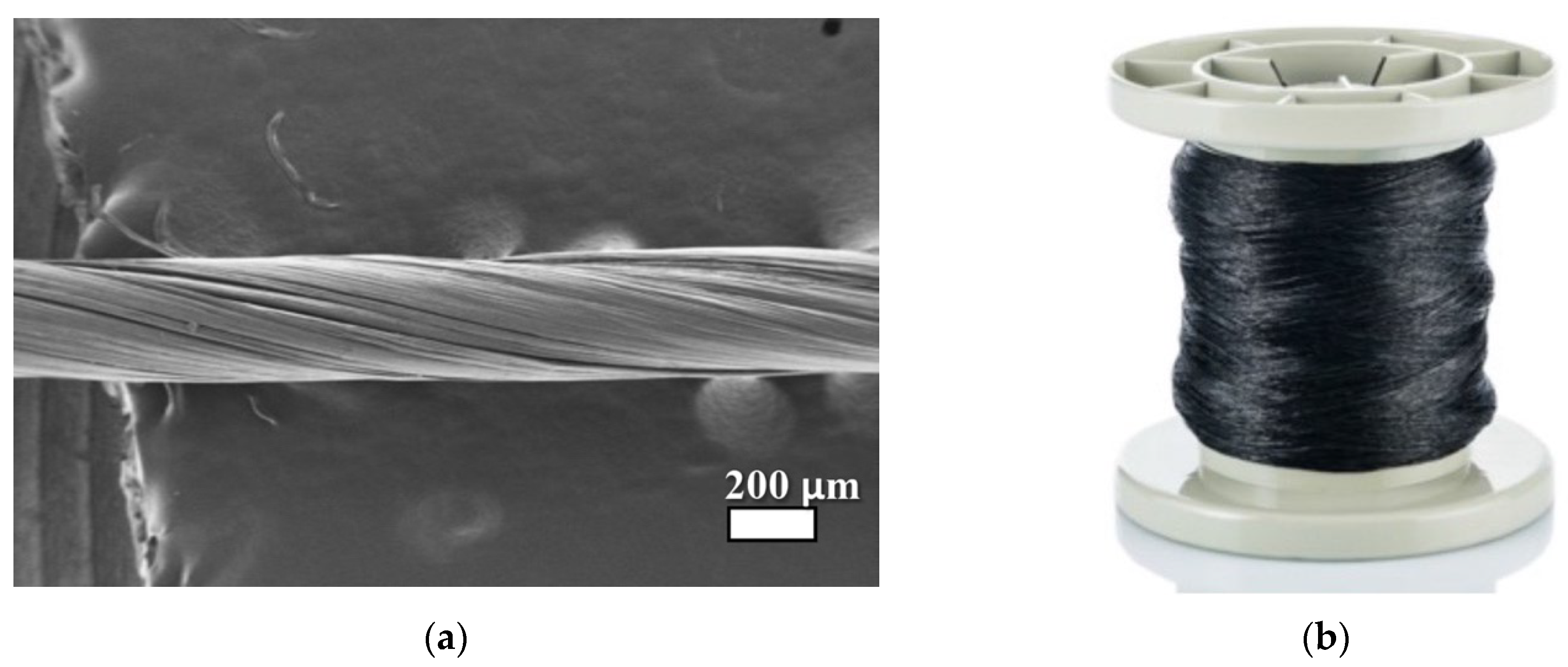
Figure 2.
Configuration of tow and coating scheme of the fiber.
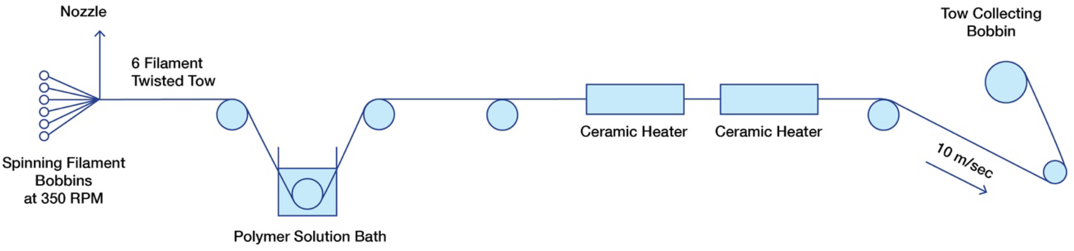
Figure 3.
HRSEM (High Resolution Scanning Electron Microscopy) images of CNT fiber (a) Pristine; (b) Coated with PVDF.
Figure 3.
HRSEM (High Resolution Scanning Electron Microscopy) images of CNT fiber (a) Pristine; (b) Coated with PVDF.
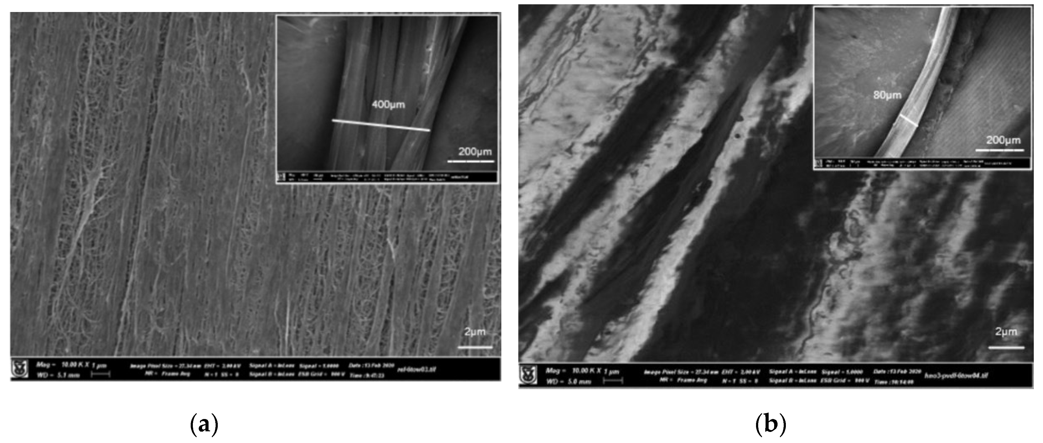
Figure 4.
HRSEM images (x500) scale bar 20µm. UCNT 6-tow yarns coated with (a) single layer; (b) Double layer of PVDF coating.
Figure 4.
HRSEM images (x500) scale bar 20µm. UCNT 6-tow yarns coated with (a) single layer; (b) Double layer of PVDF coating.
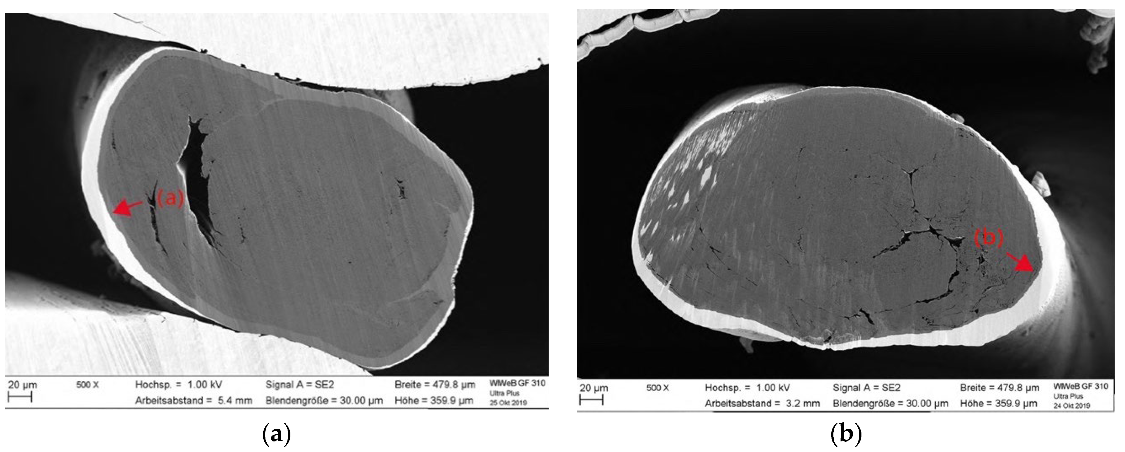
Figure 5.
HRSEM image (x2000) scale bar 10µm. PVDF coating penetrating into the outer circumference of the UCNT 6 tow yarn.
Figure 5.
HRSEM image (x2000) scale bar 10µm. PVDF coating penetrating into the outer circumference of the UCNT 6 tow yarn.
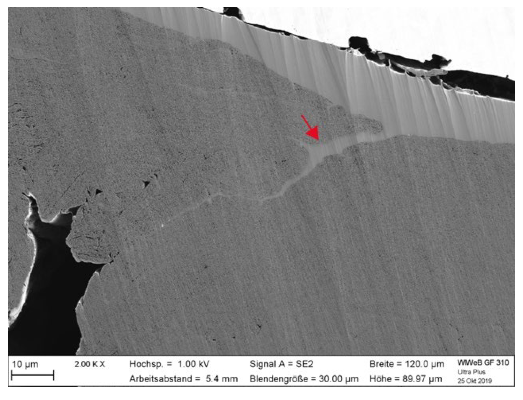
Figure 6.
Plain double weaving design (Pointcarre Textile Software).
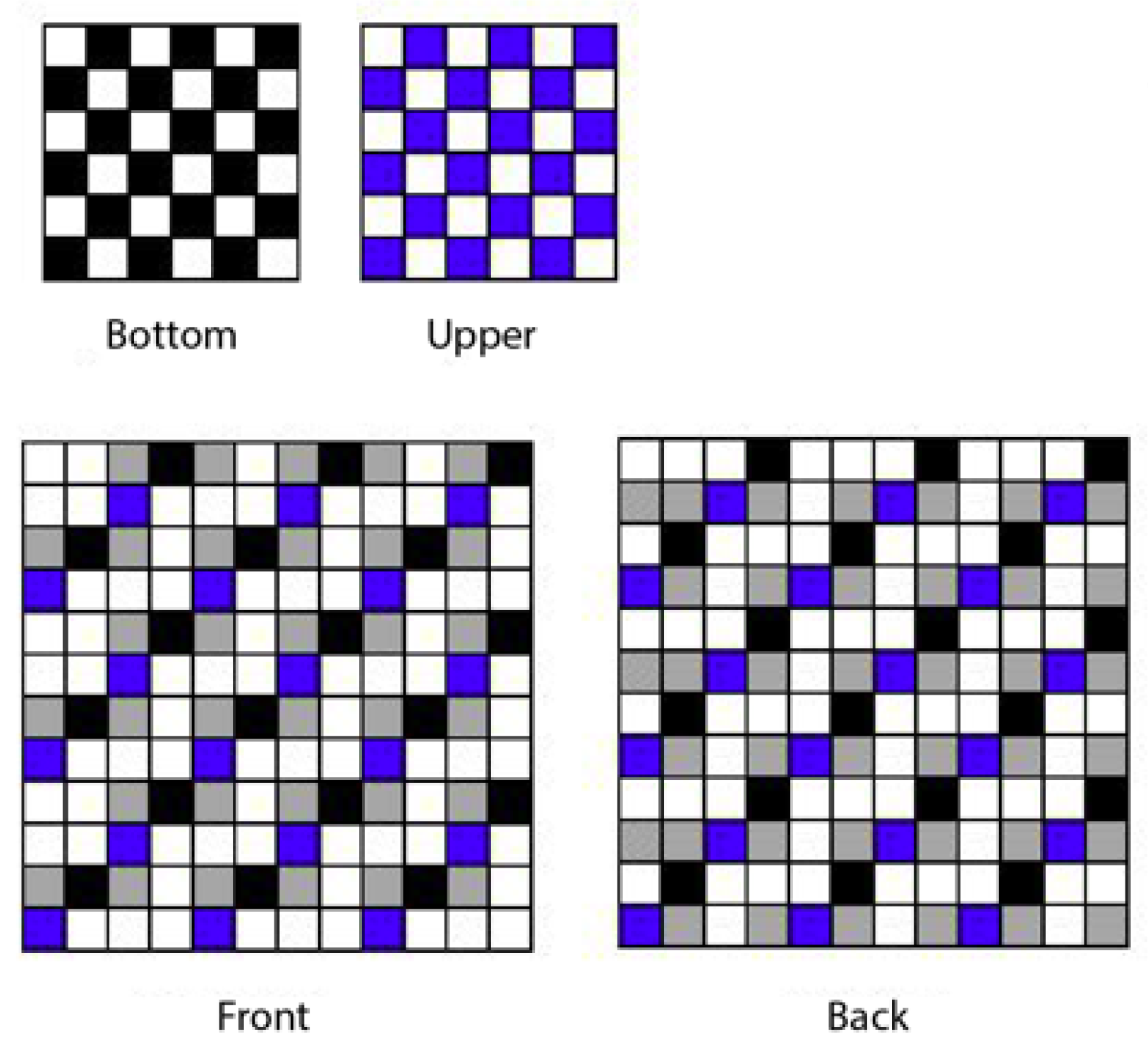
Figure 7.
Plain double-weaved diagram with conductive CNT yarn represented in red: (a) Top view; (b) Cross section view: blue and green lines represent weft alternating yarns, black cross-section circles represent warp yarns, red line represents conductive yarn.
Figure 7.
Plain double-weaved diagram with conductive CNT yarn represented in red: (a) Top view; (b) Cross section view: blue and green lines represent weft alternating yarns, black cross-section circles represent warp yarns, red line represents conductive yarn.
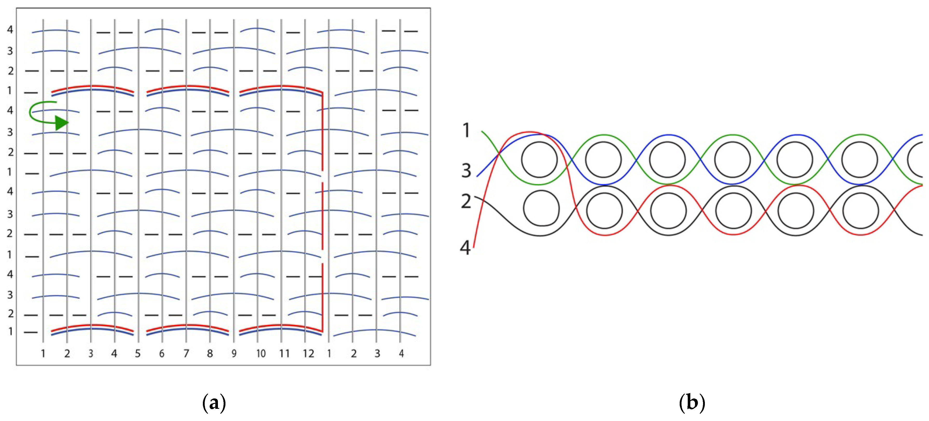
Figure 8.
Plain triple weave design (Pointcarre Textile Software).
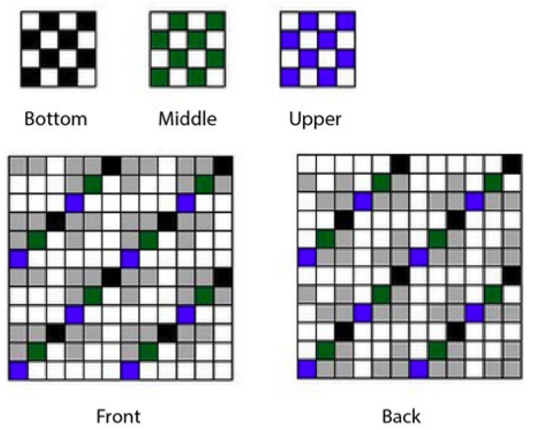
Figure 9.
Plain triple-weaved diagram with conductive CNT yarn (a) Top view; (b) Cross-section view green, blue, and yellow lines represent weft alternating yarns, black cross-section circles represent warp yarns, red line represents conductive yarn (marked as C).
Figure 9.
Plain triple-weaved diagram with conductive CNT yarn (a) Top view; (b) Cross-section view green, blue, and yellow lines represent weft alternating yarns, black cross-section circles represent warp yarns, red line represents conductive yarn (marked as C).
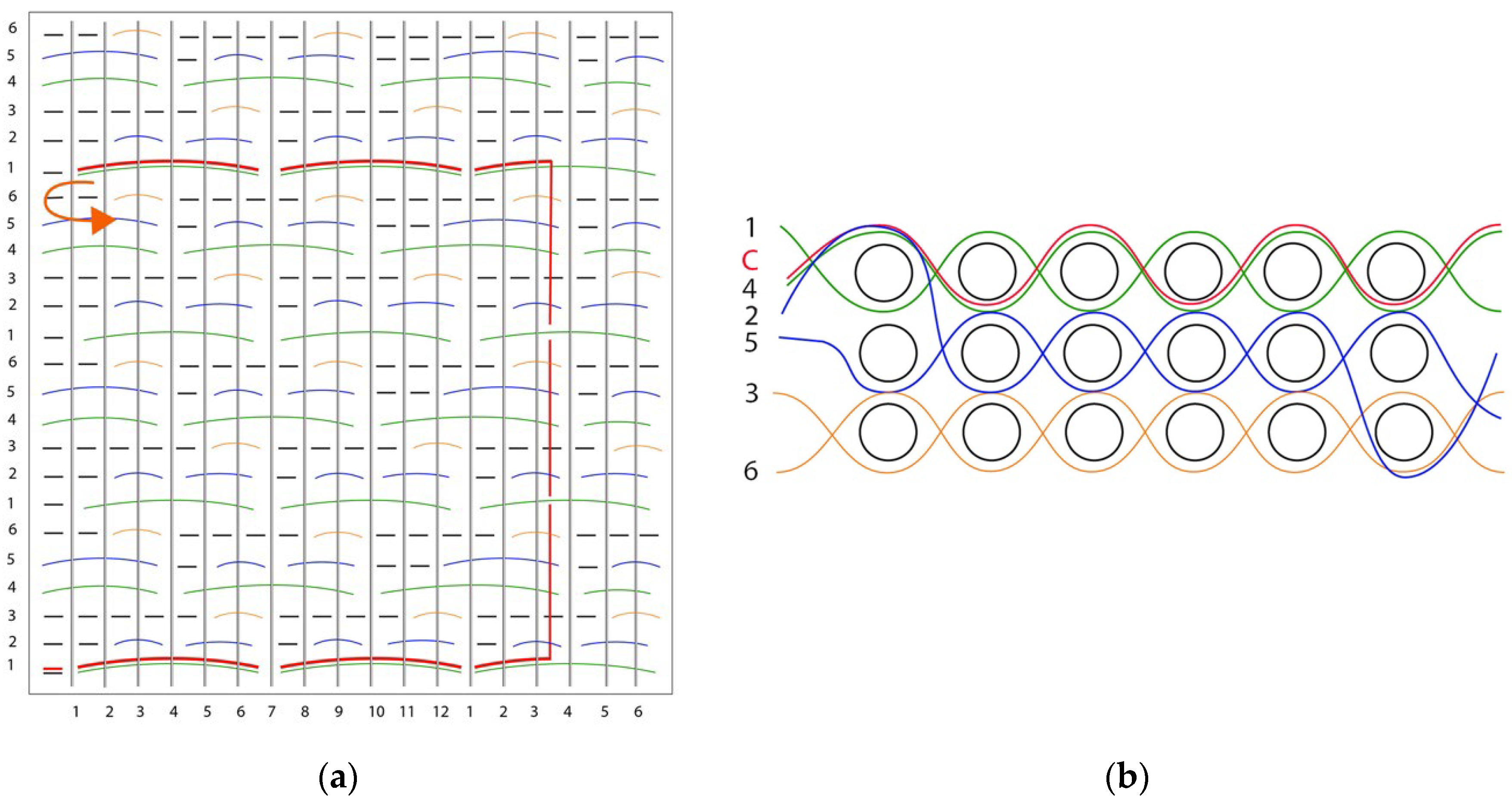
Figure 10.
Multi-layer configuration: Single layer without (1a) and with (2a) conductive yarn. Double layer with insulating back (1b) and Triple layer with insulating middle layer (2b), Multilayer configuration with EeonTexTM, conductive yarn layer and two insulating layer (1c), and multilayer configuration with 4 conductive yarn layers, two insulating layers and EeonTexTM (2c).
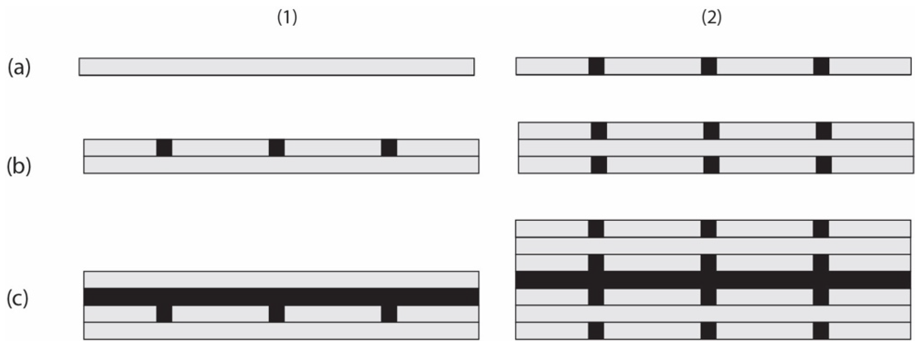
Figure 11.
Multilayer configuration with a pocket for EeonTexTM nonwoven pressure sensor.
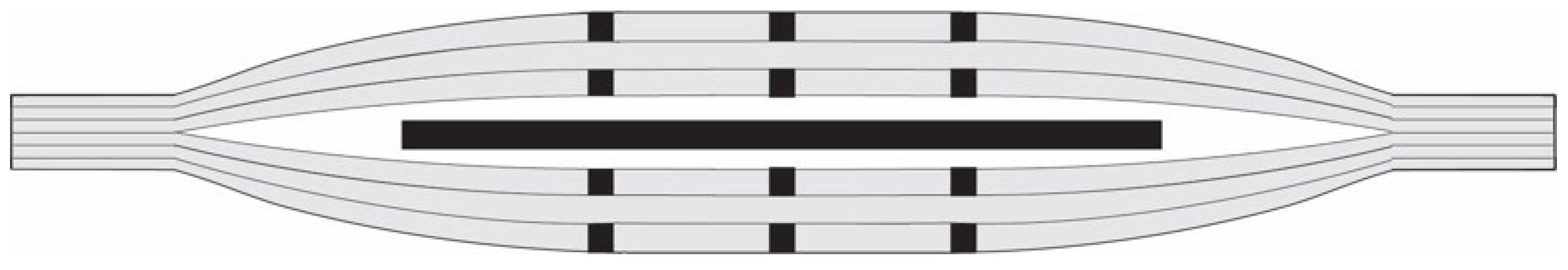
Figure 12.
(a) CNT to Flexible PCB – Soft Connections; (b) Flexible PCB design Soft to rigid connections interface, points achieved by a manual stitch.
Figure 12.
(a) CNT to Flexible PCB – Soft Connections; (b) Flexible PCB design Soft to rigid connections interface, points achieved by a manual stitch.
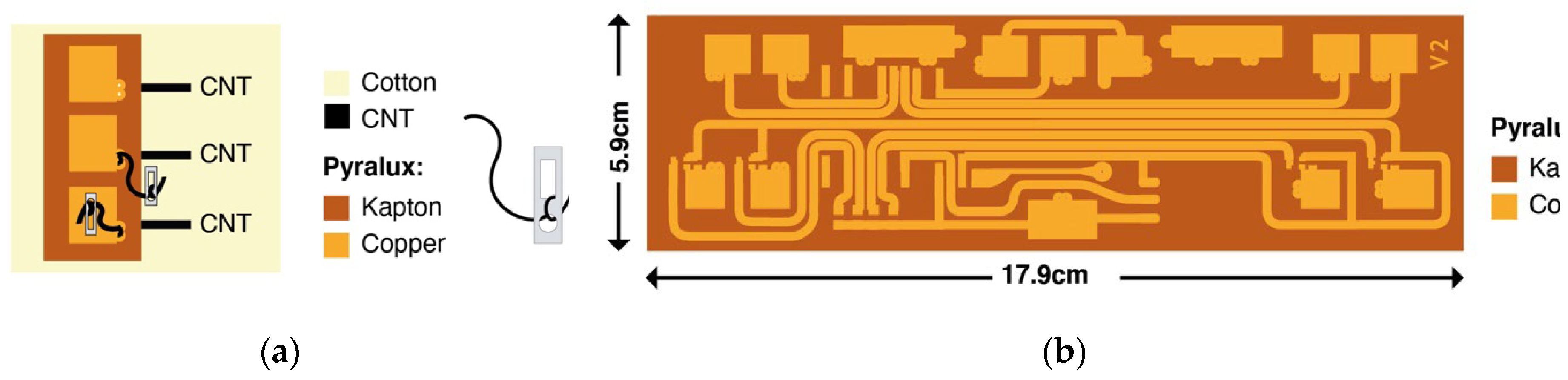
Figure 14.
(a) Different UCNT weave configuration; (b) Heating demonstrator using FLIR pocket camera.
Figure 14.
(a) Different UCNT weave configuration; (b) Heating demonstrator using FLIR pocket camera.
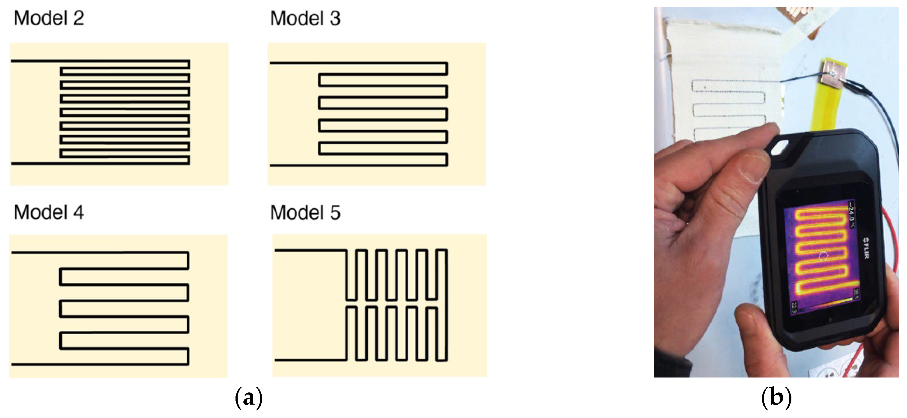
Figure 15.
EeonTexTM multi-layer structure (a) Top view of the 3 layers; (b) Side view.
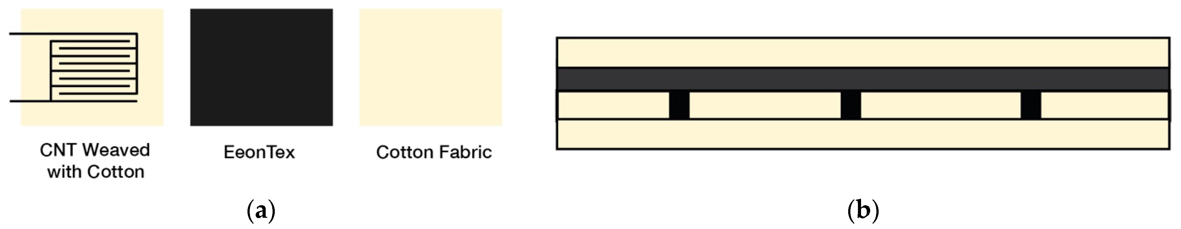
Figure 18.
(a) Sample for Abrasion Resistance test under EN-ISO 12947-3-d; (b) Image of sample after testing.
Figure 18.
(a) Sample for Abrasion Resistance test under EN-ISO 12947-3-d; (b) Image of sample after testing.
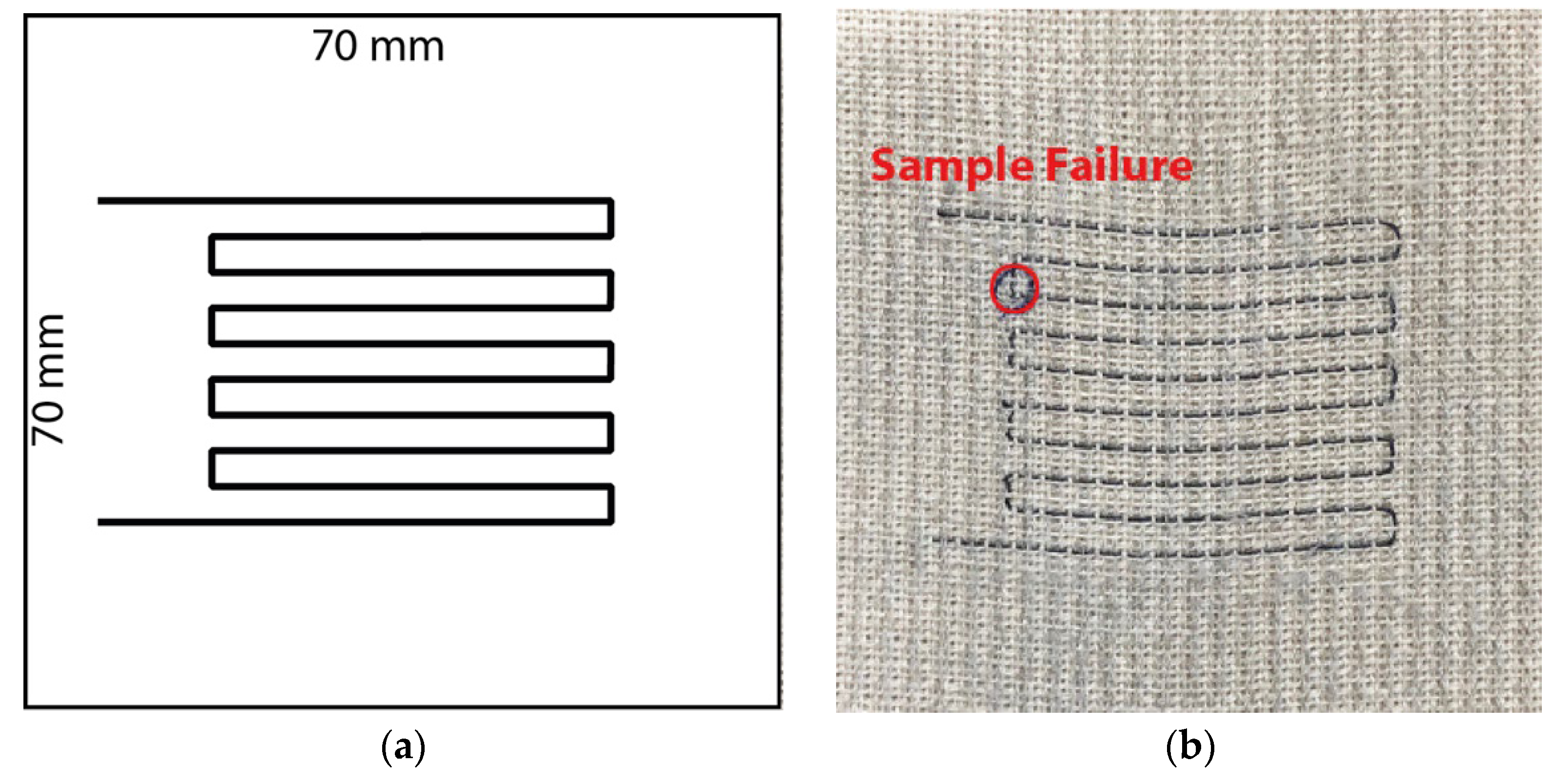
Figure 19.
(a) Sample for Abrasion Resistance test under DIN 5363-2 with sandpaper; (b) Image of sample after testing.
Figure 19.
(a) Sample for Abrasion Resistance test under DIN 5363-2 with sandpaper; (b) Image of sample after testing.
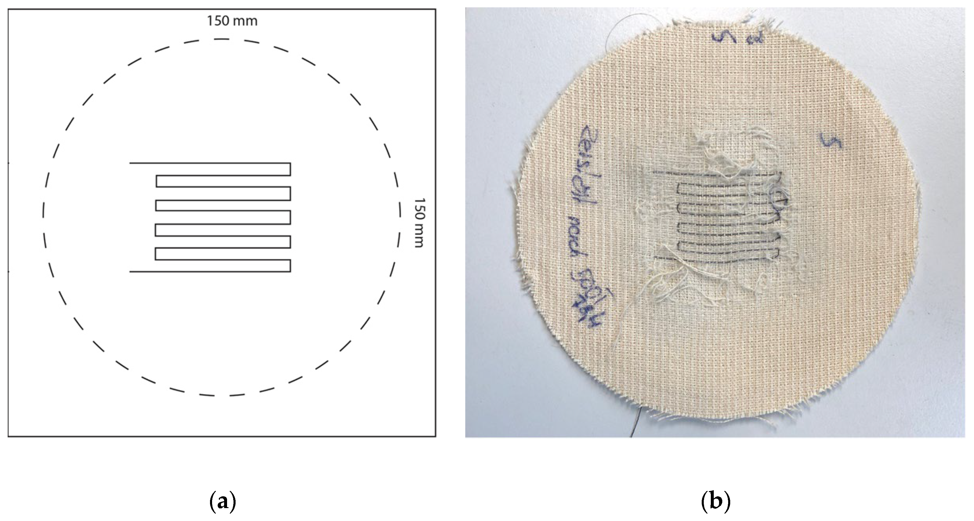
Figure 25.
Structures fall under the definition of WHO fiber dimensions (length > 5 μm, diameter < 3 nm and length-to-diameter ratio of > 3:1).
Figure 25.
Structures fall under the definition of WHO fiber dimensions (length > 5 μm, diameter < 3 nm and length-to-diameter ratio of > 3:1).
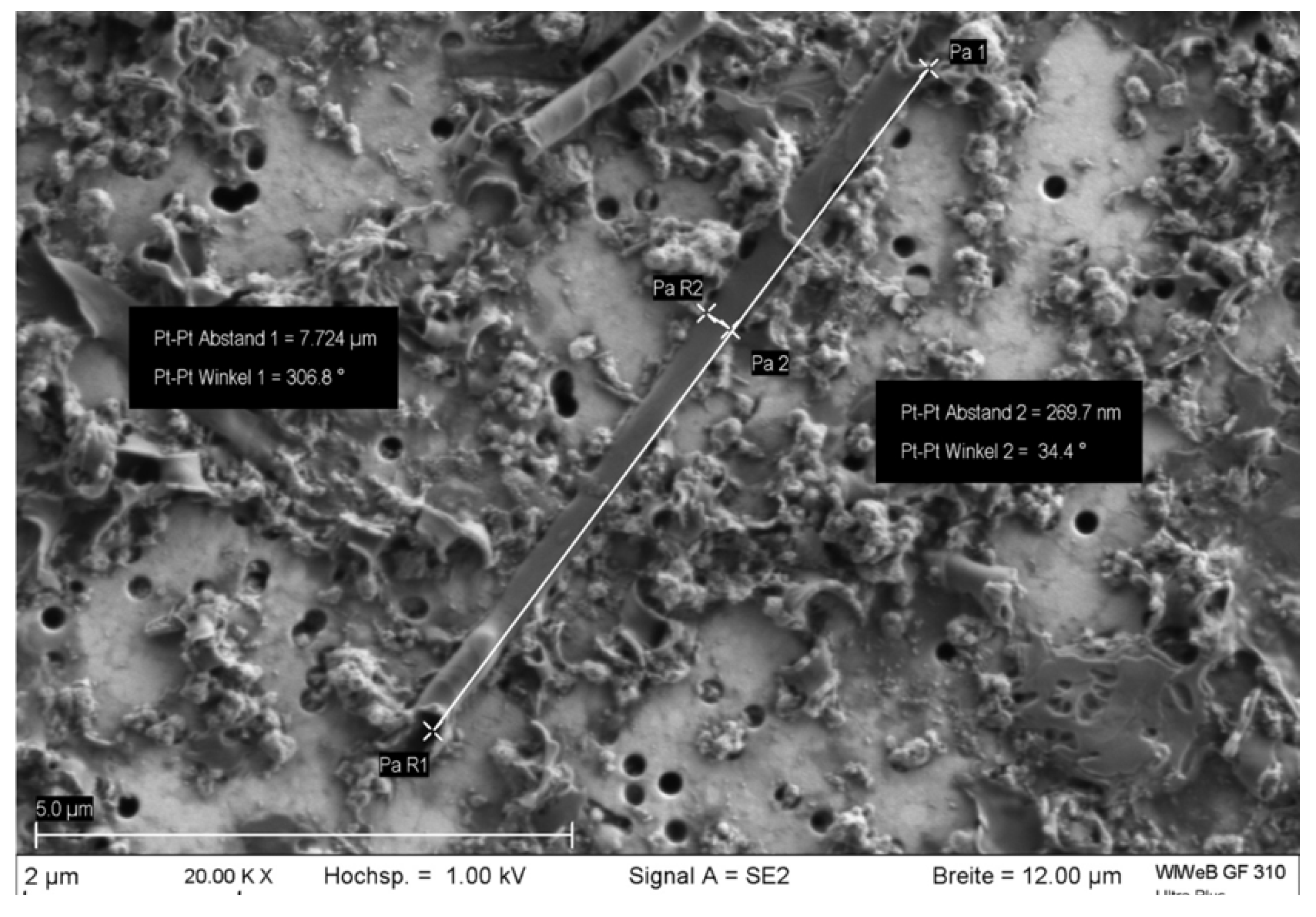
Figure 26.
Fiber structure with WHO fiber geometry. The section subjected to EDX analysis is marked in red.
Figure 26.
Fiber structure with WHO fiber geometry. The section subjected to EDX analysis is marked in red.
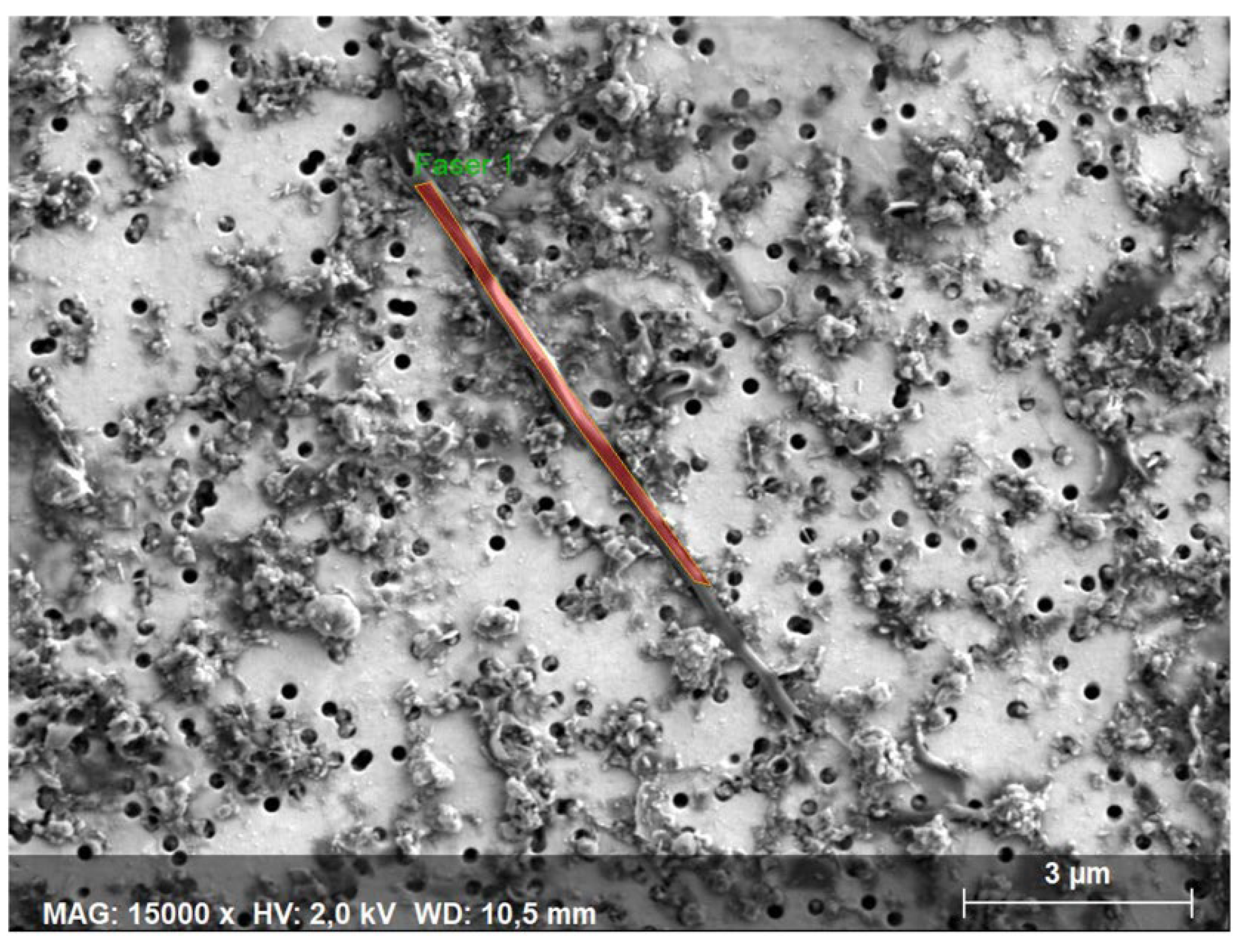
Figure 27.
EDX spectrum of the red section from Figure 26.
Figure 27.
EDX spectrum of the red section from Figure 26.
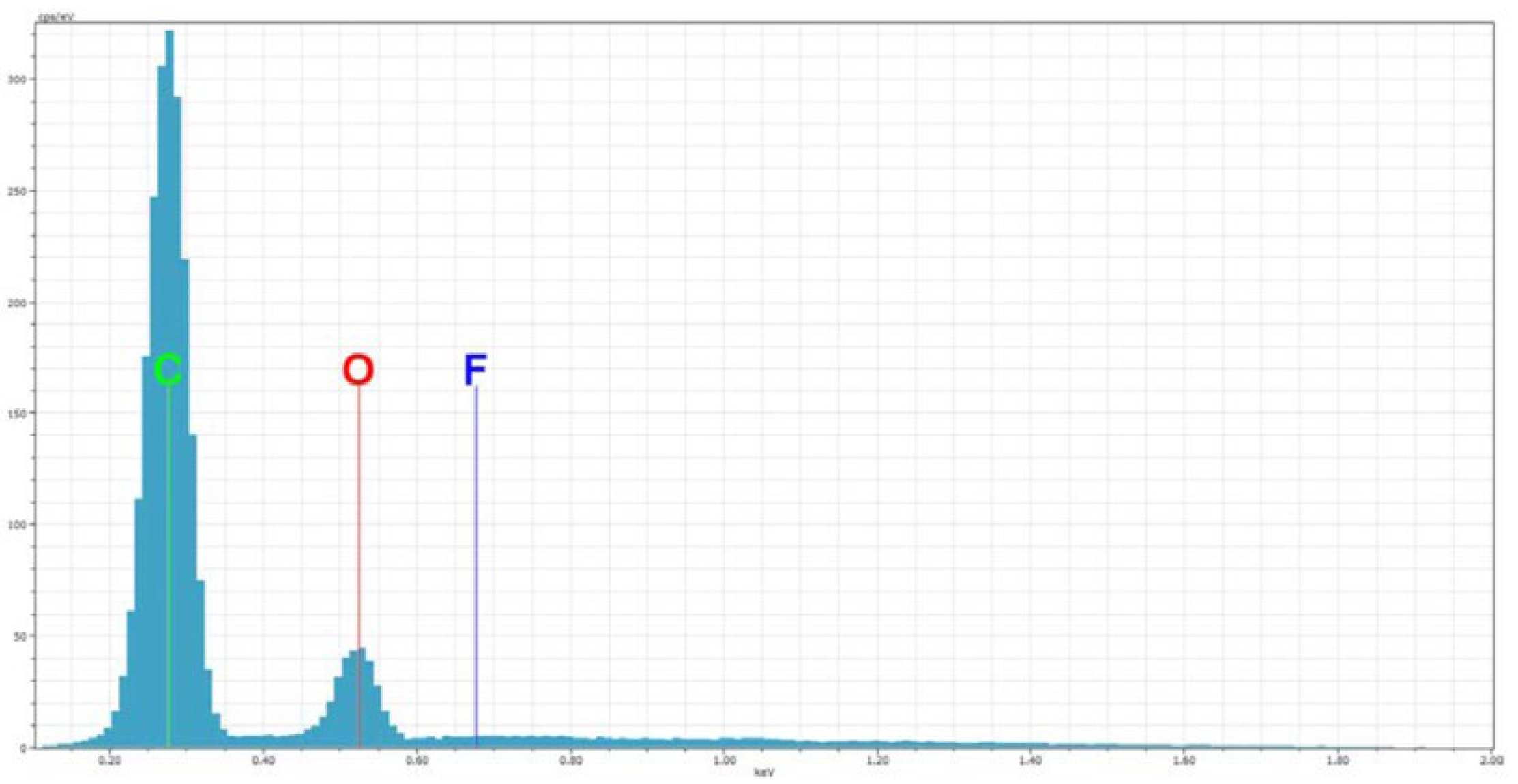

Table 1.
Coating Types - 61-V1E.
| Polyurethane (WBPU) | Epoxy | PVDF |
|---|---|---|
| UD-104 75% (25% Water) | RIMR 135+137 100% | PVDF 1000K 15% (85% Acetone) |
| UD-108 100% | RIMR 135+137 90% (10% Acetone) |
PVDF 400K 15% (85% Acetone) |
| UD-108 75% (25% Water) | RIMR 135+137 70% (30% Acetone) |
- |
| UD-375 50% (50% Water) | RIMR 135+137 50% (50% Acetone) |
- |
| UD-302 25% (75% Water) | RIMR 135+137 30% (70% Acetone) |
- |
| UD-215 100% | RIMR 135+137 10% (90% Acetone) |
- |
Table 2.
Comparative properties of CNT yarns.
| Tow | Linear density [g/km] | Diameter [µm] | Resistivity [Ohm/m] | Tenacity [N/tex] | Tensile Stress [MPa] |
|---|---|---|---|---|---|
| 1 | 4 | 200 | 880 | 0.22 | 28 |
| 6 | 27 | 400 | 120 | 0.25 | 55 |
| 6 coated with PVDF |
28 | 80 | 50 | 0.30 | 1604 |
Table 3.
Abrasion cycle tests: Single and Double-coated yarns.
| Number of Rubbing Cycles | Single-Coated Yarn - Sample 1 | Single-Coated Yarn - Sample 2 | Single-Coated Yarn - Sample 3 | Double-Coated Yarn - Sample 1 | Double-Coated Yarn - Sample 2 | Double-Coated Yarn - Sample 3 |
|---|---|---|---|---|---|---|
| 0 | - | 79.1 | 80.2 | 85.4 | 87.0 | 87.0 |
| 5,000 | 76.8 | 80.7 | 81.5 | 86.2 | 87.5 | 88.4 |
| 7,500 | 78.3 | - | - | - | - | - |
| 10,000 | 79.3 | 81.5 | 84.2 | 88.4 | 88.1 | 91.7 |
| 15,000 | 85.6 | 83.1 | 88.0 | - | - | - |
| 20,000 | - | 86.1 | Destroyed | 107.9 | 92.0 | 128.9 |
| 25,000 | Destroyed | 90.2 | - | - | - | - |
| 30,000 | 96.3 | - | - | 138.7 | 98.5 | 137.3 |
| 35,000 | 118.7 | - | - | - | - | - |
| 40,000 | Destroyed | - | - | 168.3 | 120.2 | Destroyed |
| 50,000 | - | - | - | 197.7 | 240.0 | - |
| 55,000 | - | - | - | Destroyed | Destroyed | - |
Table 4.
Combined Abrasion cycle tests: Single and Double coated yarns.
| Number of Rubbing Cycles | Single-Coated Yarn - Sample 1 | Single-Coated Yarn - Sample 2 | Single-Coated Yarn - Sample 3 | Double-Coated Yarn - Sample 1 | Double-Coated Yarn - Sample 2 | Double-Coated Yarn - Sample 3 |
|---|---|---|---|---|---|---|
| 0 | 78.4 | 81.9 | 78.7 | 89.1 | 91.3 | 87.4 |
| 100 | 79.7 | 83.8 | 80.9 | 90.9 | 95.2 | 90.2 |
| 200 | 82.1 | 87.5 | 86.0 | 94.5 | 103.2 | 95.2 |
| 300 | 86.3 | 99.0 | Destroyed | 99.5 | Destroyed | 140.2 |
| 400 | 91.0 | 116.2 | - | 106.5 | Destroyed | - |
| 500 | Destroyed | Destroyed | - | 115.7 | - | - |
| 600 | - | - | - | Destroyed | - | - |
Table 5.
Washing Test Data (Ohms).
| Test Type | Condition | Value 1 | Value 2 | Difference | Percentage Difference |
|---|---|---|---|---|---|
| 105-C12-2S (Industrial Washing) | Single coated | 58.67 | 73.83 | 15.17 | 25.85% |
| Double coated | 59.33 | 74.17 | 14.83 | 25.00% | |
| 105-C06-C1M (Domestic Washing) | Single coated | 58.25 | 67.17 | 8.92 | 15.31% |
| Double coated | 59.33 | 64.83 | 5.50 | 9.27% | |
| Sealed Test | 58.50 | 65.00 | 6.50 | 11.11% |
Disclaimer/Publisher’s Note: The statements, opinions and data contained in all publications are solely those of the individual author(s) and contributor(s) and not of MDPI and/or the editor(s). MDPI and/or the editor(s) disclaim responsibility for any injury to people or property resulting from any ideas, methods, instructions or products referred to in the content. |
© 2024 by the authors. Licensee MDPI, Basel, Switzerland. This article is an open access article distributed under the terms and conditions of the Creative Commons Attribution (CC BY) license (http://creativecommons.org/licenses/by/4.0/).
Copyright: This open access article is published under a Creative Commons CC BY 4.0 license, which permit the free download, distribution, and reuse, provided that the author and preprint are cited in any reuse.


