
Submitted:
31 December 2024
Posted:
31 December 2024
You are already at the latest version
Abstract
In this paper, a decentralized robust direct model reference adaptive controller (MRAC) is suggested for the pose control of a quadrotor unmanned aerial vehicle (UAV) in order to prevent parameter drift. The governing equations of motion referred to the rotational system of the quadrotor UAV are parameterized, in terms of a matched uncertainty by the control input, in a decentralized way from the angles of motion, where bounded perturbations are also considered. An error-dependent damping term in the update law is added to enforce robustness. Uniform ultimate boundedness of the tracking error signal is ensured. The translational dynamics are governed through a linear PID control. The performance of the decentralized robust MRAC scheme here proposed is assessed via simulation results.
Keywords:
adaptive control
; decentralized control
; e-modification
; parametric drift
; model reference control
; parametric identification
; robust control
; unmanned aerial vehicles
1. Introduction
When the system output is influenced by uncontrolled inputs, and not only by the control input, such inputs create disturbances which may affect the system in unpredictable ways. In general, external perturbations may influence the output persistently although these may be present for a limited time.
In this work, in order to assure stability and to improve the performance when considering presence of external perturbations and modeling errors in the adaptive control of the pose for a quadrotor UAV, a modification to the parametric estimation algorithm is examined, which can leads to what is known as robust learning algorithms. A robust learning algorithm is characterized by preserving, within some specifications of design, stability properties under external perturbations and modeling errors [1,2,3]. It is well known that conventional adaptive (update) laws show parameter drift in presence of external perturbations, unmodeled dynamics, measurement noise and time variations. The parameter drift is a phenomenon in which the parametric estimates drift from their ideal values, possibly to infinity . As a result of the on-line parametric estimator, when any value for the parameters does not exist from a matching condition, in the attempt to find for a function an exact matching, it brings parameter drift. Two alternatives can be addressed in order to evade parameter drift. When the training error is too small, the first one, the so-called dead-zone modification [4], consists into indirectly not performing parametric adaptation. In the last one, whether the well-known e-modification [5,6], -modification [7], also known as leakage factor [1,8], and projection algorithms [1,8,9,10,11], the on-line parametric estimator is modified such that the parametric estimates are constrained from the drift to infinity.
The design of stable adaptive controllers is the main issue when trying with asymptotic model following. Unbounded solutions could emerge when trying with unmodeled dynamics and time-varying parameters as perturbations. From systems under the effects of the presence of perturbations, exact model following is no longer possible [12]. To this last eventuality, certain performance conditions must be satisfied through the controller design task having as the main goal the boundedness for all the signals from the closed-loop system.
It is well known that in the presence of measurement noise the parametric estimates do not converge to their ideal values if the input signal does not satisfy the persistency of excitation property, in other words, if it is not sufficiently rich, which could originate that these may also drift. The use of sufficiently rich inputs can prevent the parameter drift, although when such input signal is not available then update law modifications, namely, dead-zone modification, -modification, and e-modification, could be an alternative option.
The e-modification has been developed [5] in order to overcome a limitation with the -modification in that it can achieve asymptotic tracking under certain conditions while improving robustness. The aim of the e-modification is to reduce the damping term proportionally to the tracking error norm. The damping term is reduced to zero as the tracking error tends to zero, giving back the asymptotic tracking property of the ideal case with MRAC. Nevertheless, the e-modification only achieves bounded tracking in accordance with the stability analysis, so, the ideal property of the MRAC is not preserved. Moreover, asymptotic tracking is not attained in general with increased robustness.
An adaptive controller is said to be robust if it guarantees signal boundedness in the presence of bounded perturbations, unmodeled dynamics, and time delay [1,2,4,7,13].
In this work, a decentralized direct MRAC for the pose of a quadrotor UAV with e-modification in the update law, in order to evade parameter drift, here is proposed. The rotational dynamics from the quadrotor UAV is parameterized in the form of a decentralized model with matched uncertainties via control channels. This parametrization is preferred due to the matched uncertainties supply an extra realism to the ideal system. Also, MRACs are designed from each subsystem that constitutes the whole rotational system. Simulation results validate the proposal.
The manuscript is organized as follows. In Section 2 is described the nonlinear dynamic model of the quadrotor. The parameterized model for the quadrotor is given in Section 3. In Section 4, the design of the decentralized robust MRAC is developed. In Section 5, simulation results about the validation of the proposal are discussed. The conclusion is drawn in Section 6.
2. Quadrotor’s Dynamics
In this work, a four-rotor helicopter having one pair of rotors rotating clockwise and the remaining pair of rotors rotating counterclockwise is considered. Each rotor comprises a DC motor, a rotor blade and a drive gear. By increasing the speed of the rear rotor while simultaneously reducing the forward rotor by the same amount the forward motion is fulfilled. Backward, leftward, and rightward motion are fulfilled in the same manner. By accelerating the two clockwise turning rotors while decelerating the counterclockwise ones is performed the yaw motion.
The dynamics from a quadrotor is described through the equations of motion derived from the rigid body theory with six degrees of freedom [14], which can be decoupled into kinematic and dynamic equations [15]. The dynamic equations
are derived from the center of mass, with denoting the quadrotor mass, is for the velocity in the body frame, is the angular rate of the quadrotor, is the inertia matrix, the external force takes into account the total thrust, the quadrotor weight, and the aerodynamic force, whereas the external torque considers the aerodynamic moment vector and the difference of torque and thrust wielded by the two pairs of rotors. From a Z-Y-X sequence, consider the rotation matrix
with , , and the Euler angles denoting yaw, pitch, and roll, respectively, where the and functions are abbreviated by and , respectively. The angular velocity vector and the vector of Euler angles are related by
where , and
is nonsingular inside the region where the Euler angles are allowed to take values.
The propeller dynamics is reduced to linear relationships between the force and moment of the propellers and the squared rotor angular rate given as
with the rotor angular rate, and b denoting drag and thrust coefficients, respectively, where i is the motor index. All the motors are aligned with the vertical axis of the body frame, so, force and moments arise in the z-direction of the body frame, where is negative being consistent with the downward z-axis convention. The motor torque inputs are linked to the rigid body forces and moments through the mapping
where l denotes the distance between the center of mass (center of gravity) and the rotors from the quadrotor. The resultant gyroscopic moment is determined by the rotational velocity of the quadrotor and the sum of angular velocity of the rotors . denotes the inertia of the rotating rotors, having the same parametric value for each one of the four rotors.
Asumming low speeds, the equations of motion for a quadrotor in terms of the Euler angles are then given by [16]
where z is for the translational vertical (altitude) dynamics. , , and are moments of inertia in the direction of the three-dimensional Cartesian coordinates.
It can be seen that the rotational dynamics is intrinsically highly coupled by the angles of motion.
3. Decentralized Robust MRAC Design
3.1. Quadrotor’s Parametric Model
In this work, a decentralized robust MRAC for the pose of a quadrotor UAV is proposed.
Consider the set of state variables as given by
The description of the model (9)-(12) from the quadrotor in state–variable equations then takes the form
Under the assumption that Euler angles change slightly during flying, the gyroscopic torques are neglected and the rotational subsystem can be partitioned in the form
with and .
In order to achieve the goal of pose control task for the quadrotor UAV via a decentralized MRAC design approach, (15) is parameterized in the form
with , , , , , , , and
From the decentralized parametric model for the rotational dynamics of the quadrotor, it must be noticed that since the rotational dynamics is intrinsically highly coupled (interconnected) by the angles of motion, an interconnection matrix here is not defined in contrast with the decentralized adaptive control methodology from [7].
3.2. Robust MRAC Design from Unmatched External Perturbations
Consider a nonlinear MIMO system of the form [2]
where is the system state, is the known control matrix, is the control input, and are unknown constant matrices. The pair () is controllable with a diagonal matrix with elements strictly positive. The uncertainty is introduced for modeling errors or to model control failures. The unknown vector–function represents the system matched uncertainty. is a linear combination of N known locally Lipschitz–continuous basis functions with unknown constant coefficients. So,
with a constant matrix of the unknown coefficients and is the measurable signals (regressor) vector [3]. From (21), it is said that the uncertainties are matched in the sense that these enter to the system dynamics through control channels. So, the system controllability property is not affected as long as is invertible. More even, the matched uncertainty assumption implies existence of at least one control solution capable of steering the system state along the desired trajectories [2]. The quantity (22) is called a parametric matched uncertainty since it appears in the range space of the control input matrix B. When a parametric uncertainty is matched, the control input can cancel out the uncertainty completely when the adaptation is perfect [13].
This study is centered in the design of a MIMO state feedback adaptive controller such that the system state x globally uniformly asymptotically follows the state of the reference model
where is Hurwitz, , and is the bounded command vector. It is also required that during tracking, all signals in the closed–loop system remain uniformly bounded.
In general, there is no guarantee that ideal gains and satisfy the matching conditions
given . Anyway, the pair ( can be selected such that (24)-() have one solution pair from the premise that the structure of A may be known.
Thus, given any bounded command, the control input needs to be chosen such that the tracking error
globally uniformly asymptotically tends to zero, i.e.,
From every subsystem (18),(19),(20) it is desirable that the closed-loop dynamics takes the form
with a perturbation term. Thus, selecting the control input
and substituting (29) in (28) results
with
the parametric estimation error, and
the tracking error equation.
To guarantee uniform ultimate boundedness (UUB) of all signals in the closed-loop system consider the Lyapunov function candidate
with the adaptation gain matrix and the symmetric positive-definite solution from the Lyapunov equation. Its time derivative along the tracking error dynamics (33) results
which can be rewritten as
So, selecting the adaptive law
the time derivative (36) is then simplified to
and, consequently, outside of the set
The trajectories of the error dynamics (33) enter a compact set in finite time and remain there for all future times [17]. Nevertheless, is not compact in the space. Certainly, because the parametric estimation error is not constrained at all, is unbounded. Consequently, can become positive inside and the parametric error may diverge, even though the tracking error norm stays finite at all times [2]. This phenomenon is known as parameter drift induced by the perturbation . Hence, this argument claims that the update law (37) is not robust to bounded perturbations.
3.3. Robust MRAC Design via e-Modification
To gain robustness, from (37) the update law
is selected, which includes an extra term adding a tracking error-dependent damping, which will tends to zero as the tracking error signal decreases, to the adaptive dynamics with , a design parameter, strictly positive constant.
By definition,
with and the minimum diagonal element of and the Frobenius norm, respectively. From the Schwarz inequality,
By completion of squares, the first terms can be written as
Also, the remaining terms, by completion of squares, can be written as
Then, (45) can be rewritten as
Consequently, if
or
Hence, outside of the compact set
closed and bounded, so, .
Thus, (51) proves UUB tracking of the external command r by the output . So, in the presence of bounded time-varying perturbations and parametric uncertainties , command tracking is accomplished. Moreover, the command tracking problem for the MIMO system dynamics (28) is solved, which can be formulated as is shown next.
Theorem 1. Given the MIMO dynamics (18) with control uncertainty and matched unknown function , the MRAC subsystem (29), (31), (32), (40) imposes uniform ultimate bounded tracking of the reference model (23), driven by any bounded time–varying command . Also, all signals from the respective closed–loop subsystem are UUB in time.
4. Simulation Results
Simulation results about the performance of the decentralized robust MRAC are argued. Both absence and presence of perturbations are considered when evaluating the proposal. A Gaussian noise source is considered as the source of perturbations. The command signal to be tracked is exacting and the simulation time is extended in order to search for the parameter drift. From [18,19], with , , , , and selecting and , the matching conditions (Eqs. (24), ()) are then satisfied to ideal gains and [20].
The symmetric positive-definite matrix
results from solving the Lyapunov equation
for
The adaptation gain for the update law (40) is chosen as . The same design procedure is followed for pitch and yaw angles subsystems, so, only the design procedure for roll angle stabilization is given. The same P matrix is obtained when considering the same values for , , and Q matrix. However, the remaining adaptation rates are chosen as and .
Simulation results from Figure 1, Figure 2, Figure 3, Figure 4 and Figure 5 show the performance of the decentralized robust MRAC in absence of perturbations when performing model reference tracking to the pose of the quadrotor UAV. In this work, it has been corroborated that in absence of perturbations the parametric estimates tend to their ideal values in contrast with that proposal in [23], where the parametric estimates from the adaptive law with -modification tend to the origin. Simulation results from Figure 6, Figure 7, Figure 8, Figure 9, Figure 10, Figure 11, Figure 12 and Figure 13 show that the decentralized robust MRAC is capable to confronting the perturbations when performing the task of model reference following to the quadrotor UAV’s pose. Figure 14 and Figure 15 show the parametric estimates dynamics from the adaptive law with e-modification (40) but from different values for when the quadrotor UAV is under the influence of external perturbations. It should be noticed that the results about the model reference following by the decentralized direct MRAC for these latter cases are not included since these are very similar to those shown from Figure 7, Figure 8, Figure 9, Figure 10, Figure 11, Figure 12 and Figure 13.
The norms and bounds of the error signal from the decentralized system are exhibited from Table 1, Table 2 and Table 3 for different values of in the update law (40). So, from Table 1, Table 2 and Table 3, it can be seen that the inequality (49) is satisfied. Then, from Theorem 1, the robust model reference tracking problem under external unmatched perturbations for the MIMO system is solved.
5. Conclusions
It can be seen that, from simulation results, the parametric estimates from the adaptive laws converge to their ideal values in absence of perturbations. By the contrary, in the presence of external perturbations the parametric estimates tend to the origin, i.e., the parametric estimates from the adaptive laws do not drift to infinity when the decentralized MRAC for the pose of the quadrotor UAV has to confronting external perturbations. From the above, it can be concluded that the decentralized MRAC is robust. Also, the parametric estimation errors (31) do not converge to the origin when the decentralized MRAC is under the influence of external perturbations. Moreover, it must be noticed that the quadrotor UAV arrives to the reference for the altitude in both scenarios.
Author Contributions
Conceptualization, F.J.; investigation, F.J. and E.J.O.V.; methodology, F.J.; formal analysis, F.J. and E.J.O.V.; validation, F.J. and E.J.O.V.; software, F.J.; data curation, F.J. and E.J.O.V.; visualization, F.J. and E.J.O.V.; writing–original draft preparation, F.J.; writing–review and editing, F.J.; supervision, F.J.; funding acquisition, F.J.; resources, F.J.; project administration, F.J. The authors have read and agreed to the published version of the manuscript.
Funding
This research was funded by Tecnológico Nacional de México (TecNM) through project 20496.24-P and, partially, under a grant 43433 from the EDD 2023 program.
Conflicts of Interest
The author declares no conflict of interest.
Abbreviations
The following abbreviations are used in this manuscript:
| DC | Direct current |
| MIMO | Multiple-input multiple-output |
| MRAC | Model reference adaptive control |
| PID | Proportional-integral-derivative |
| UAV | Unmanned aerial vehicle |
| UUB | Uniform ultimate boundedness |
References
- Ioannou, P.A.; Sun, J. Robust Adaptive Control; Prentice Hall PTR: Upper Saddle River, NJ, USA, 1995.
- Lavretsky, E.; Wise, K.A. Robust and Adaptive Control with Aerospace Applications; Springer–Verlag: London, 2013.
- Ioannou, P.; Fidan, B. Adaptive Control Tutorial; SIAM: Philadelphia, PA, USA, 2006.
- Peterson, B.B.; Narendra, K.S. Bounded error adaptive control. IEEE Trans. Automat. Contr. 1982, 27, 1161-1168.
- Narendra, K.S.; Annaswamy, A.M. A new adaptive law for robust adaptive control without persistency of excitation. IEEE Trans. Automat. Contr. 1987, 32, 134-145.
- Narendra, K.S.; Annaswamy, A.M. Stable Adaptive Systems; Prentice Hall: Englewood Cliffs, NJ, USA, 1989.
- Ioannou, P.A.; Kokotovic, P.V. Adaptive Systems with Reduced Models; Springer: New York, NY, USA, 1983.
- Åström, K.J.; Wittenmark, B. Adaptive Control, 2nd ed.; Addison-Wesley: New York, NY, USA, 1995.
- Slotine, J.J.E.; Coetsee, J.A. Adaptive sliding controller synthesis for nonlinear systems. Int. J. Contr., 1986, 43, 1639-1651.
- Farrell, J.A.; Polycarpou, M.M. Adaptive Approximation Based Control; Wiley: Hoboken, NJ, USA, 2006.
- Bodson, M. Adaptive Estimation and Control; Independently published: Coppell, TX, USA, 2020.
- Slotine, J.J.E.; Li, W. Applied Nonlinear Control; Prentice Hall: Englewood Cliffs, NJ, USA, 1991.
- Nguyen, N.T. Model-Reference Adaptive Control A Primer; Springer International Publishing AG: Switzerland, 2018.
- Etkin, B.; Reid, Ll.D. Dynamics of Flight, Stability and Control, Third Edition; John Wiley & Sons: New York, NY, USA, 1996.
- Nijmeijer, H.; van der Schaft, A. Nonlinear Dynamical Control Systems; Springer–Verlag: New York, NY, USA, 1990.
- Bouabdallah, S.; Murrieri, P.; Siegwart, R. Design and Control of an Indoor Micro Quadrotor. Proceedings of the IEEE Int. Conf. on Robotics & Automation, New Orleans, LA, USA, 2004.
- Khalil, H.K. Nonlinear Systems. Third ed.; Prentice Hall: Upper Saddle River, NJ, USA, 2002.
- User Manual QBall 2 for QUARC, Quanser Inc., Ontario, Canada, 2014.
- Jurado, F.; Lopez, S. A wavelet neural control scheme for a quadrotor unmanned aerial vehicle. Phil. Trans. R. Soc. A., 2018, 376:20170248.
- Jurado, F.; Lopez, S.; Dzul, A.; Rodríguez-Cortés, H. Decentralized control of the quadrotor’s 6-DOF. Proceedings of the 2017 Int. Conf. on Mechatronics, Electronics and Automotive Engineering (ICMEAE), Cuernavaca, Mexico, 2017.
- Jurado, F.; Hernández, R. Decentralized MRAC with integral action for attitude control of a quadrotor UAV. Proceedings of the 2018 IEEE Int. Autumn Meeting on Power, Electronics and Computing (ROPEC), Ixtapa, Mexico, 2018.
- Åström, K.; Hagglund, T. PID Controllers: Theory, Design, and Tuning, 2nd ed; ISA - The Instrumentation, Systems and Automation Society, 1995.
- Jurado, F. Decentralized Robust Direct MRAC for the Attitude of a Quadrotor UAV. In Adaptive Control Theory and Applications; Ioannou, P., Ed.; IntechOpen Limited: London, United Kingdom, 2024; pp. 73–88.
Figure 1.
Parametric estimates and under absent perturbations.
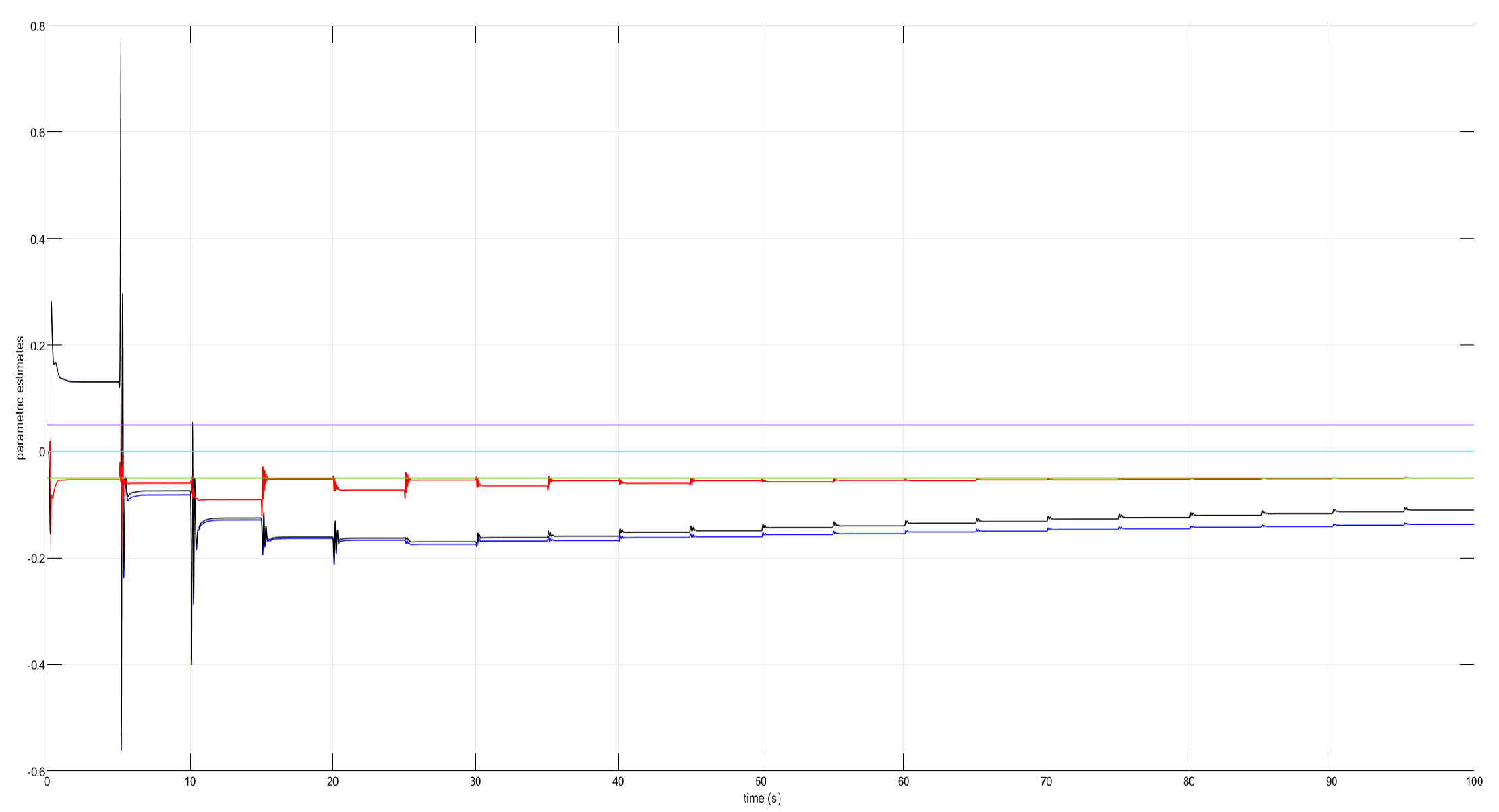
Figure 2.
Command signal tracking from the roll angle under absent perturbations.
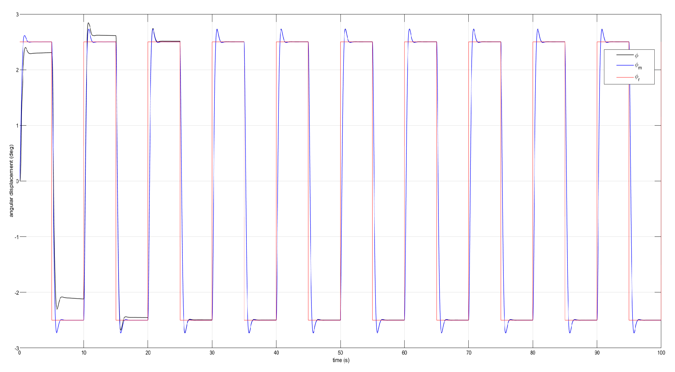
Figure 3.
Command signal tracking from the pitch angle under absent perturbations.
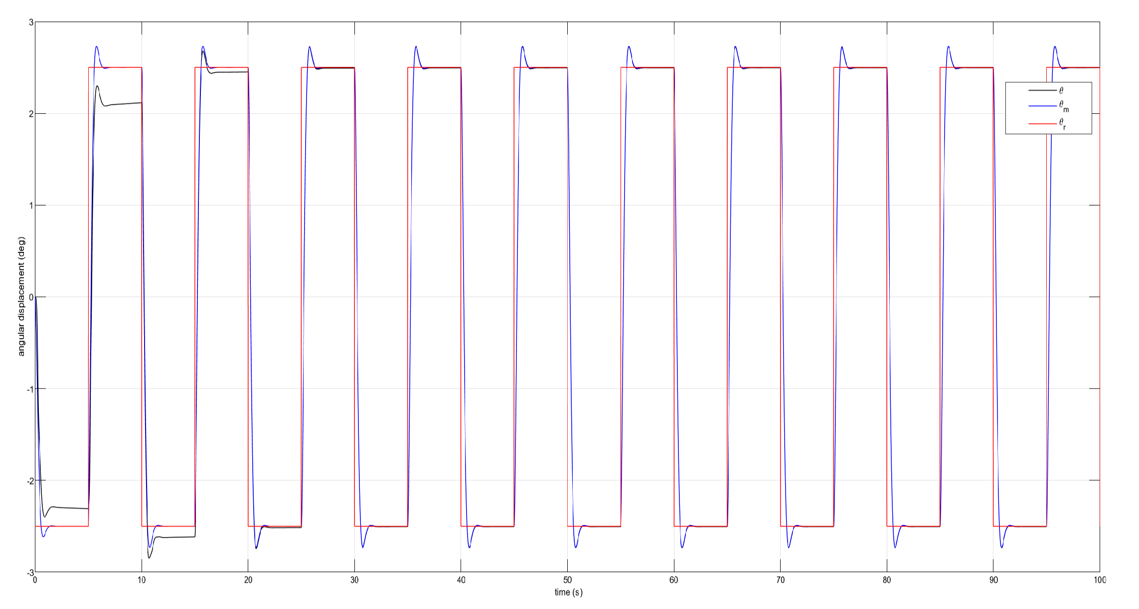
Figure 4.
Reference model following by the yaw angle under absent perturbation.
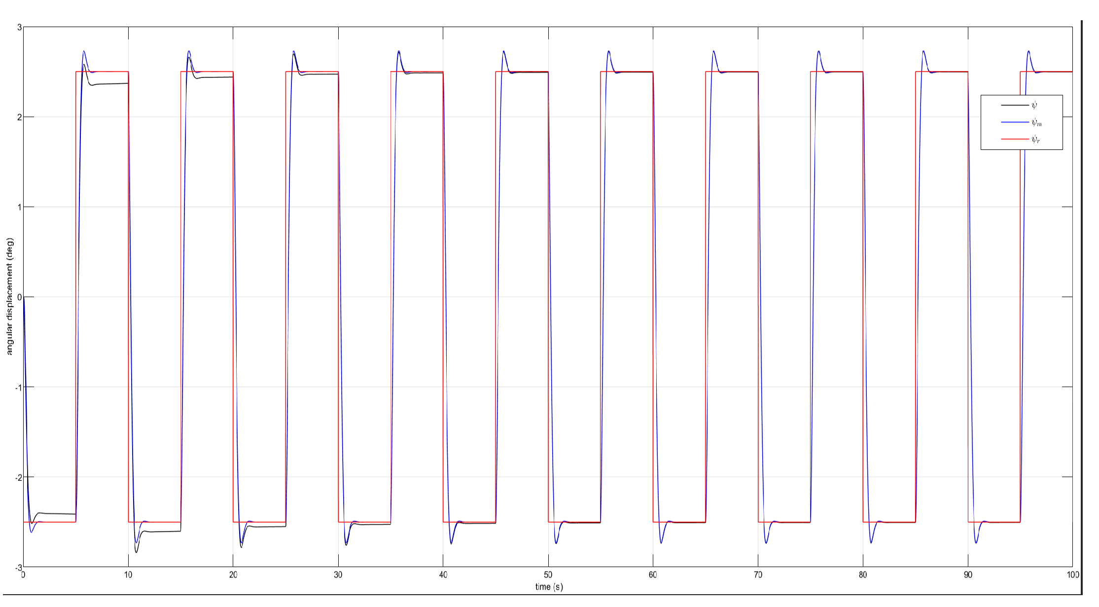
Figure 5.
Torque signals and in absence of perturbations.
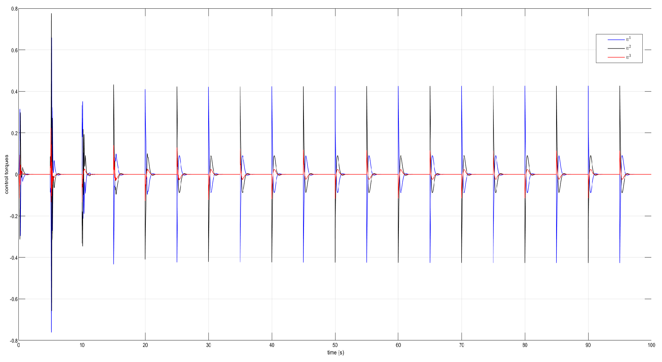
Figure 6.
Parametric estimates and in the appearance of perturbations.
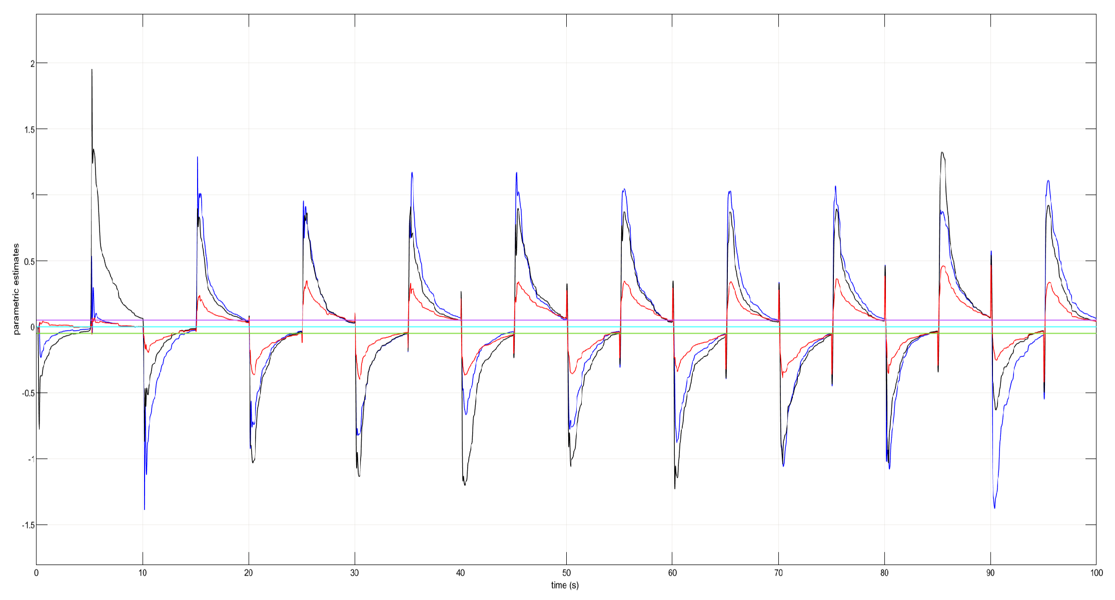
Figure 7.
Command signal tracking by the roll angle under perturbations.
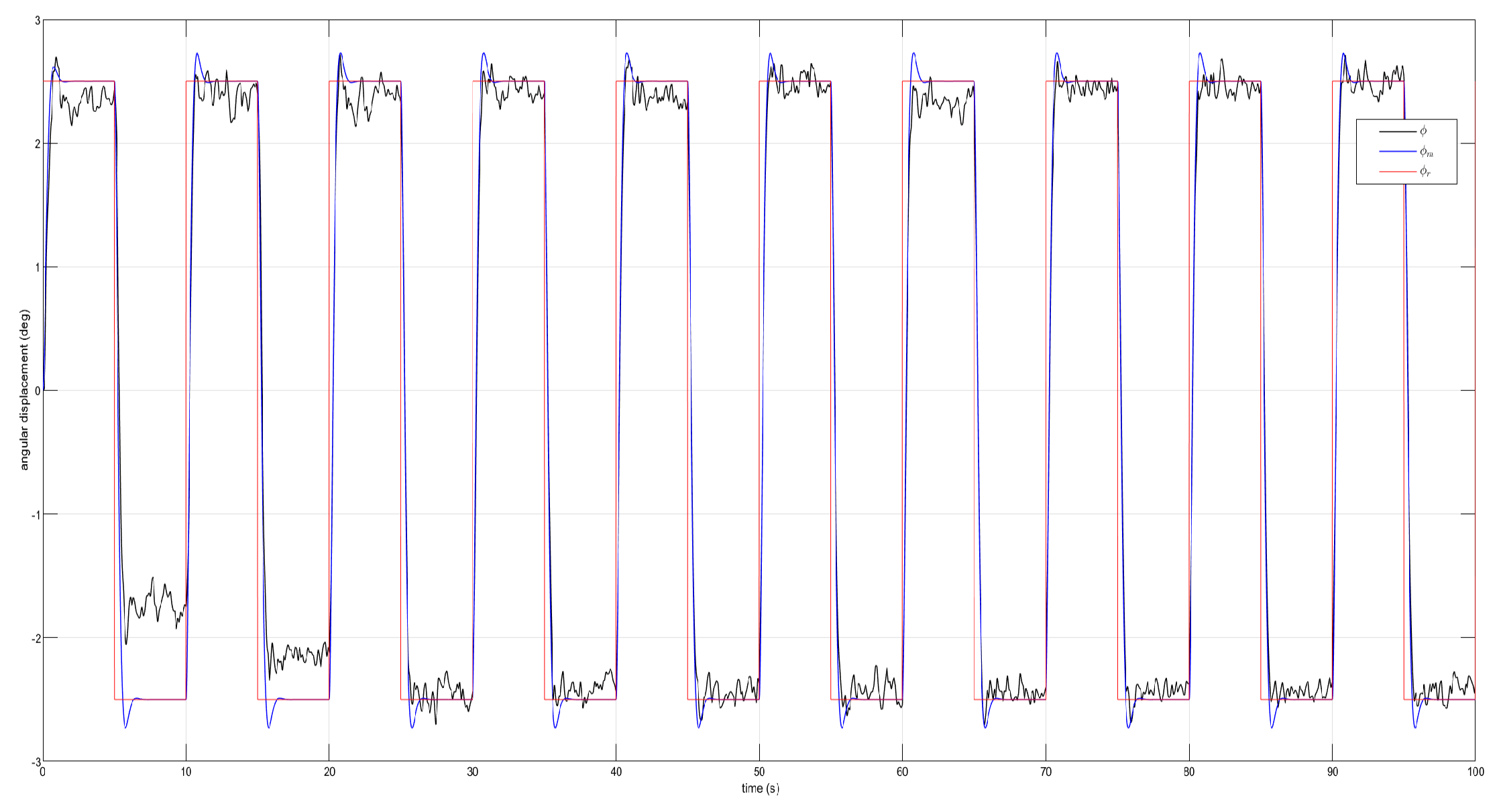
Figure 8.
Command signal tracking by the pitch angle under perturbations.
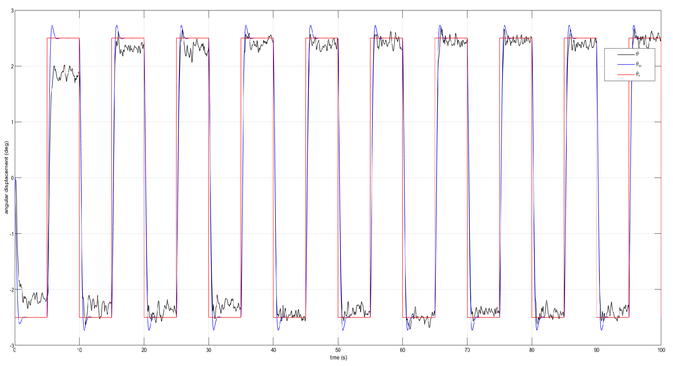
Figure 9.
Reference model following by the yaw angle under external perturbations.
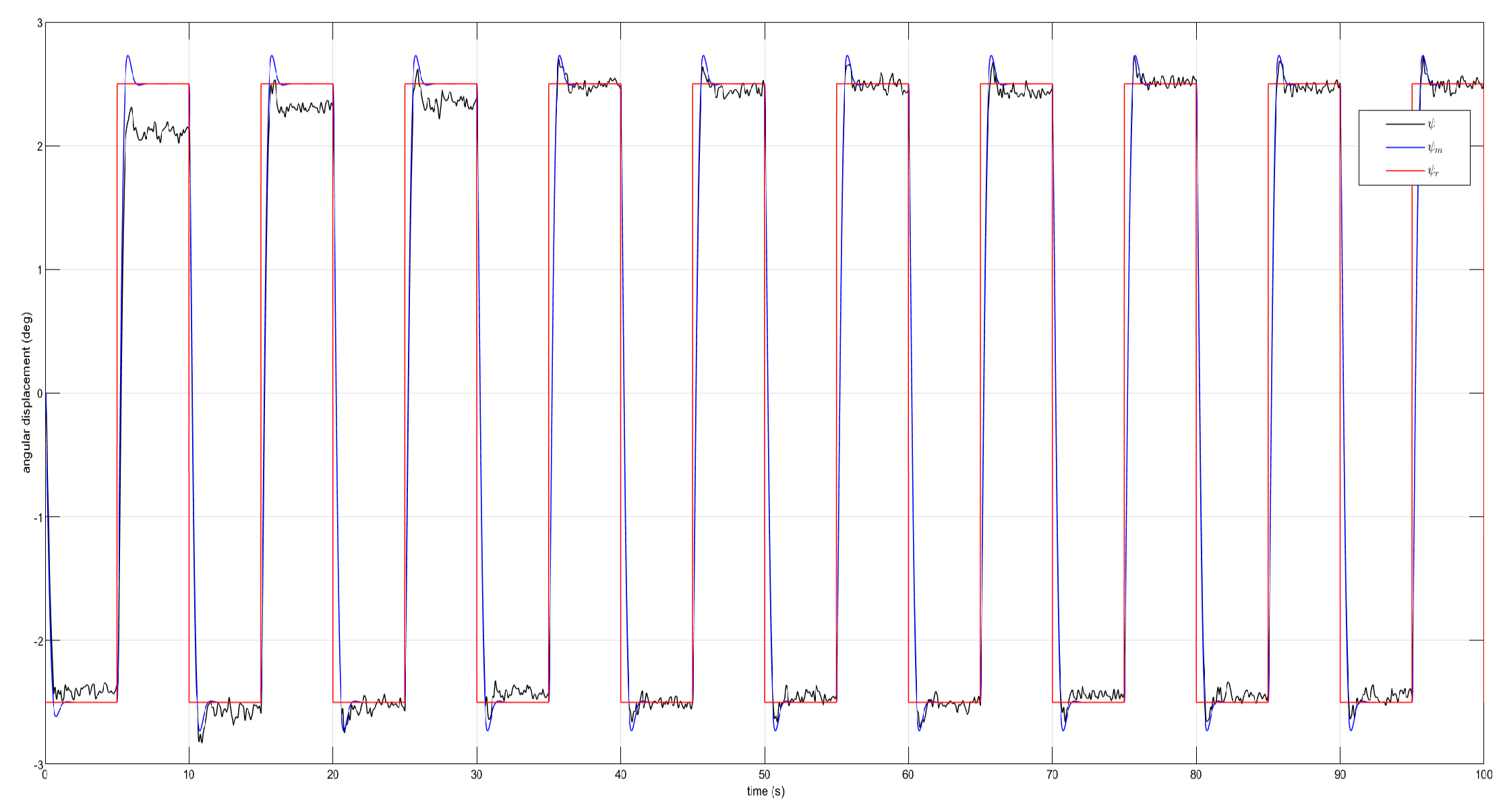
Figure 10.
Tracking error from the dynamics of the roll angle.
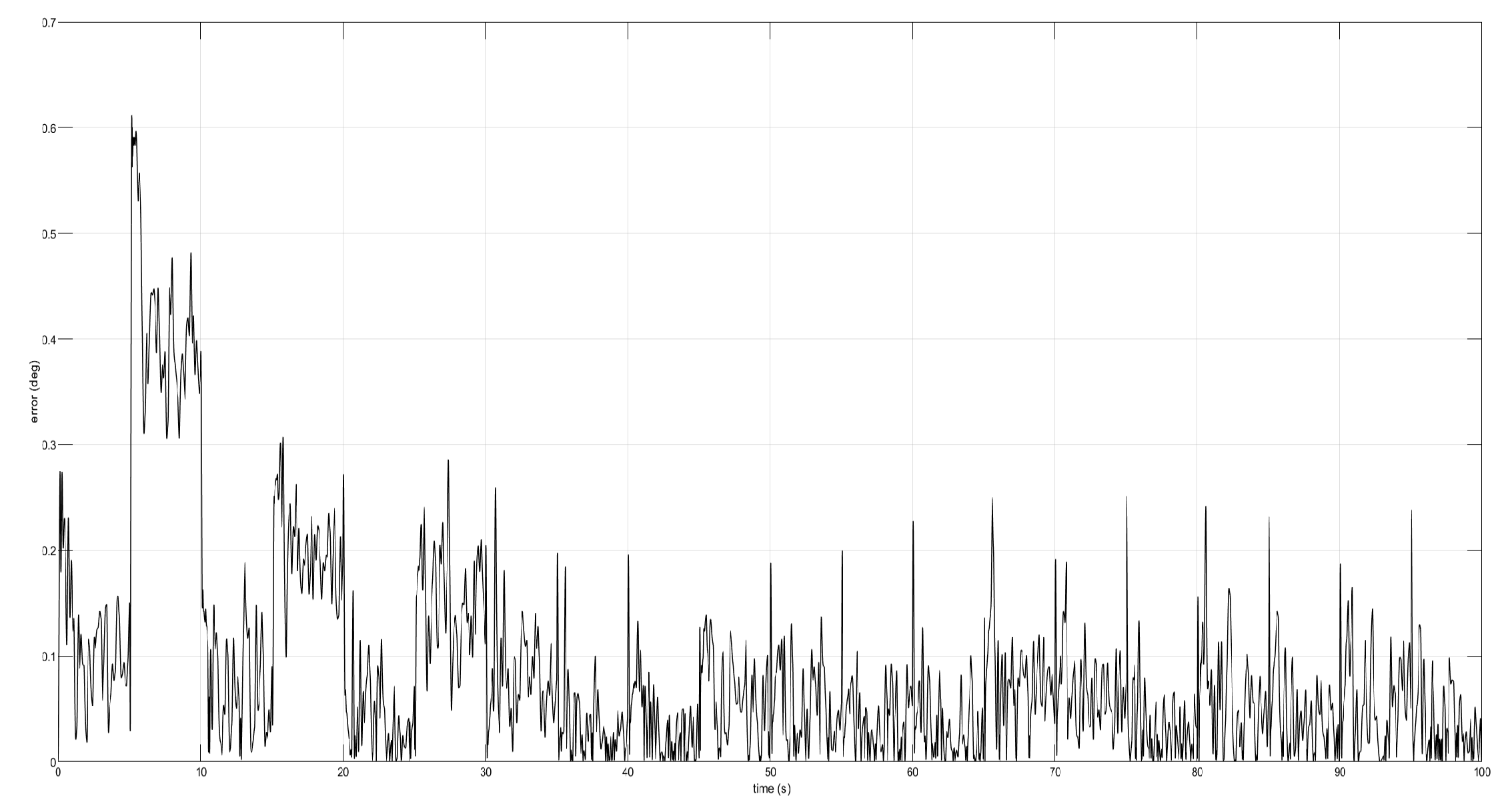
Figure 11.
Tracking error from the dynamics of the pitch angle.
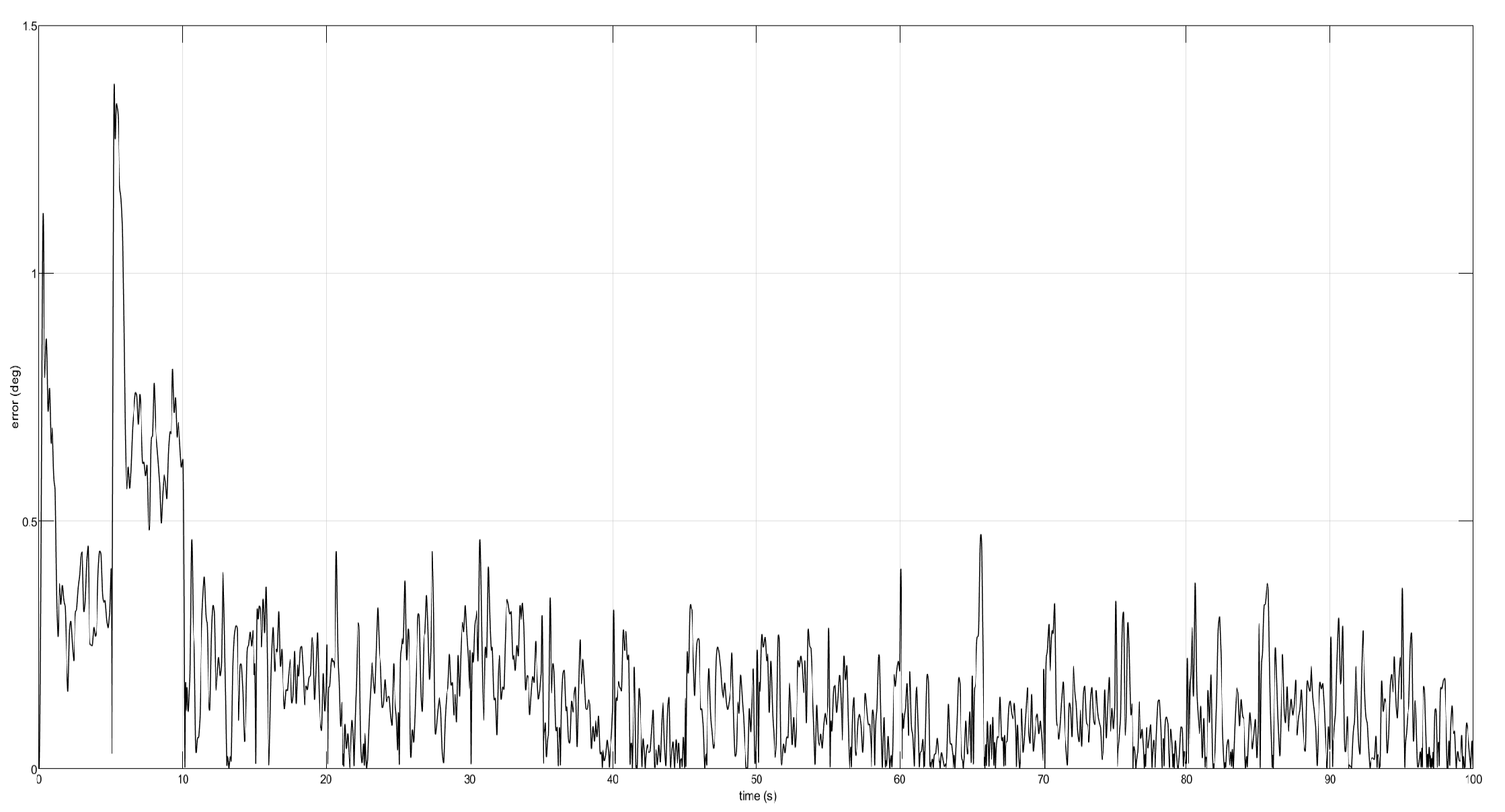
Figure 12.
Tracking error from the dynamics of the yaw angle.
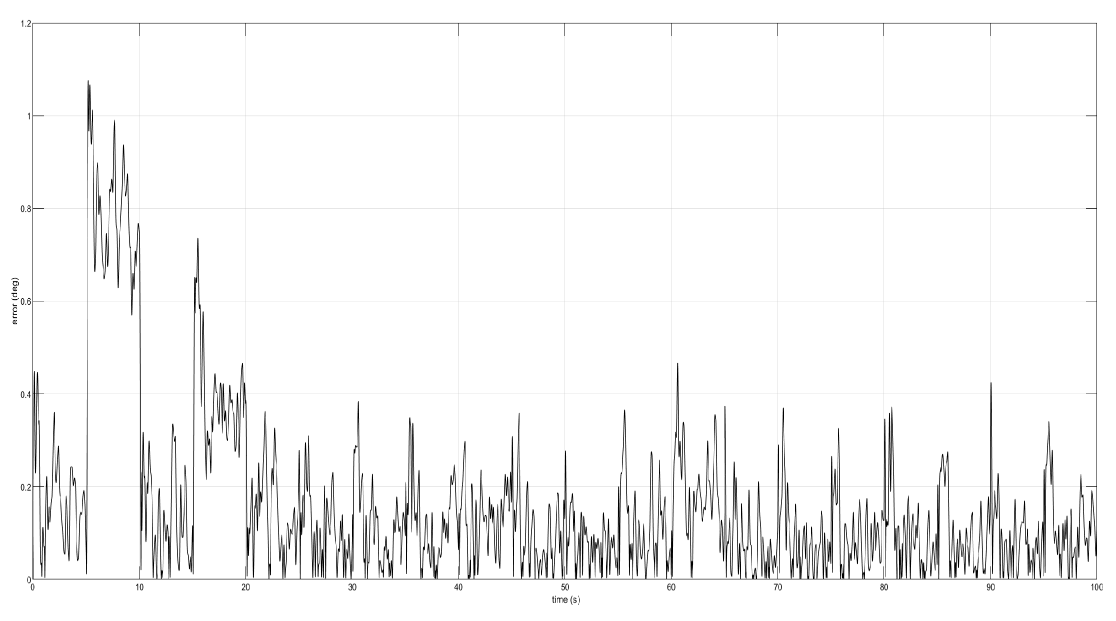
Figure 13.
Torque signals and when confronting perturbations.
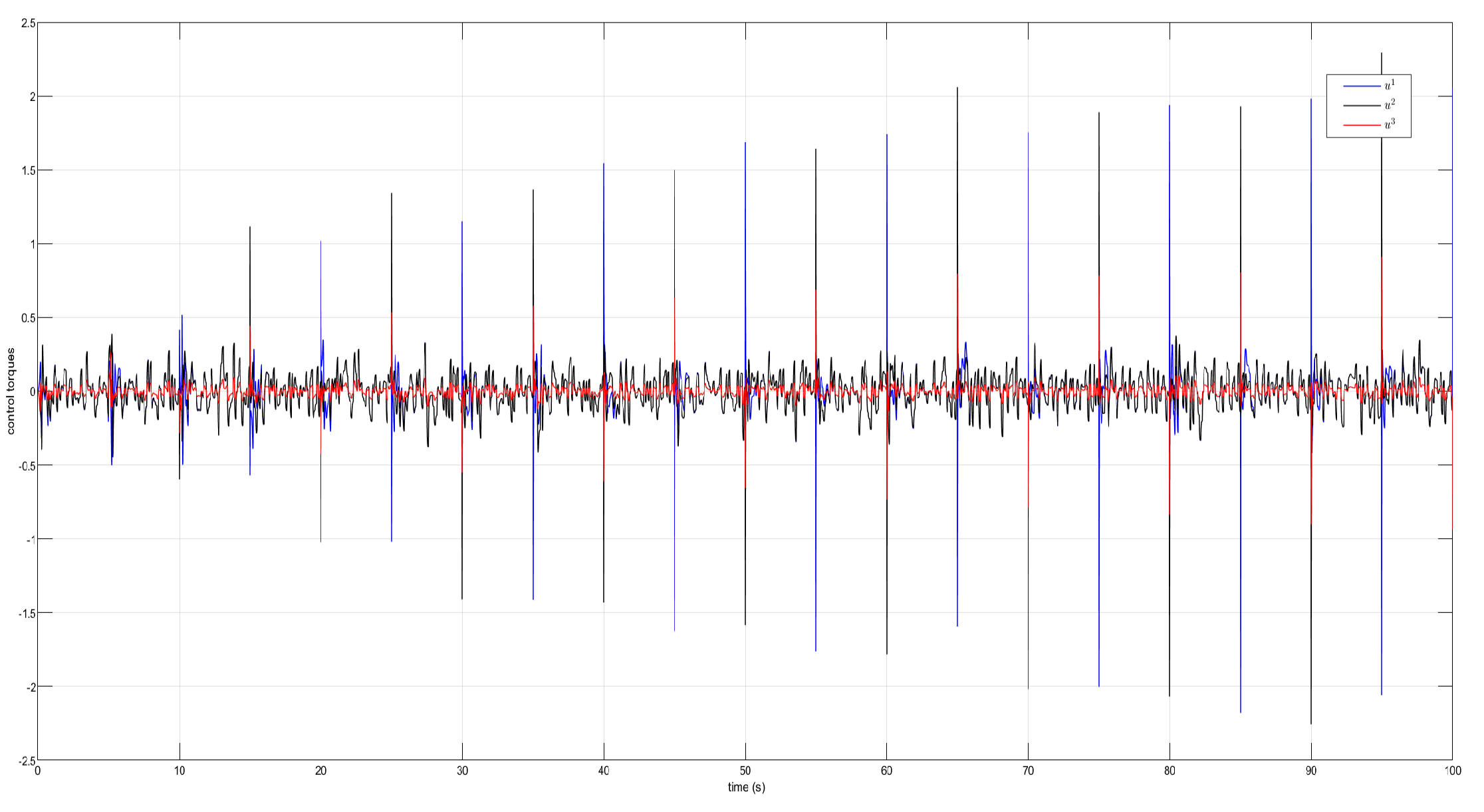
Figure 14.
Parametric estimates and under perturbations for .
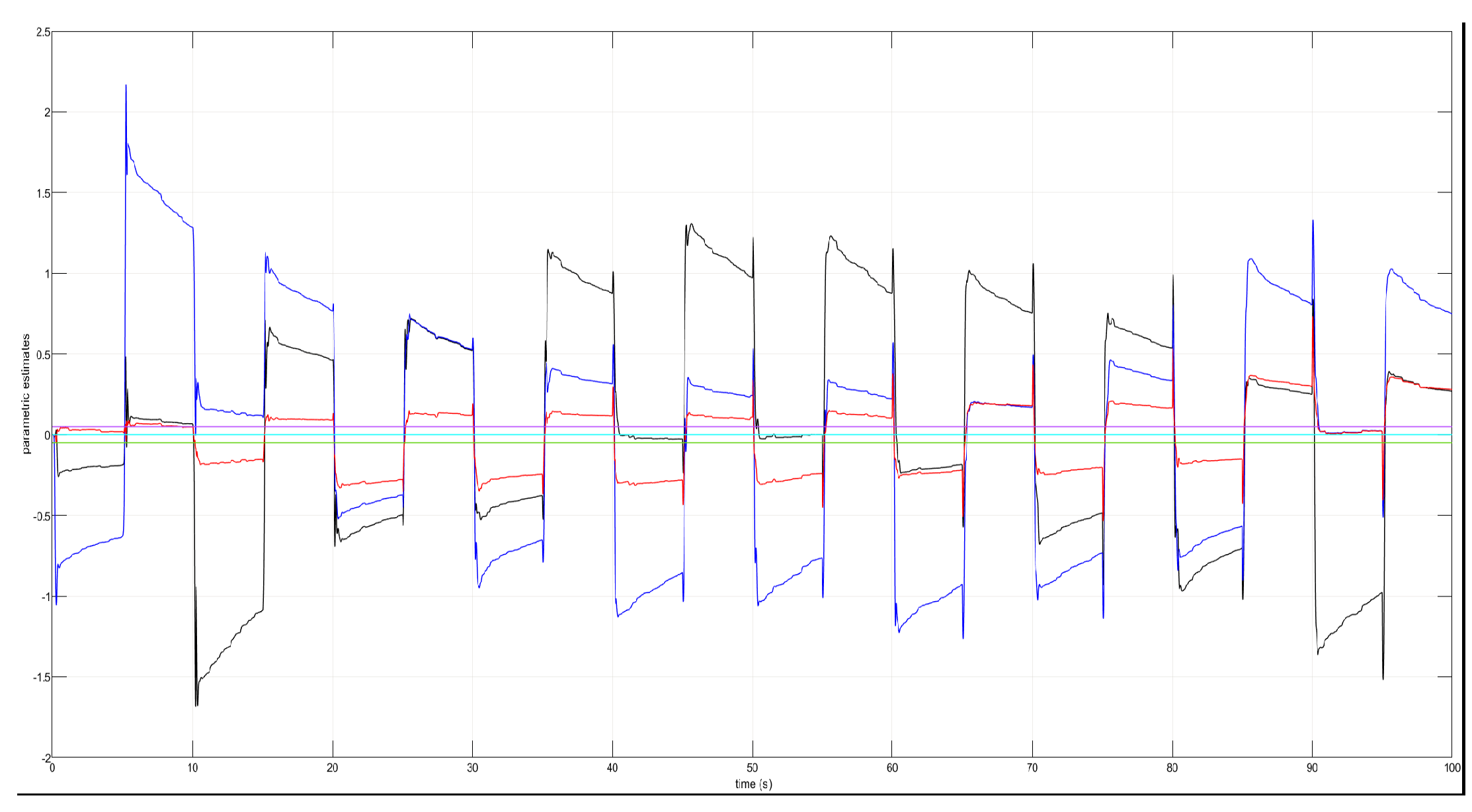
Figure 15.
Parametric estimates and in the appearance of perturbations for .
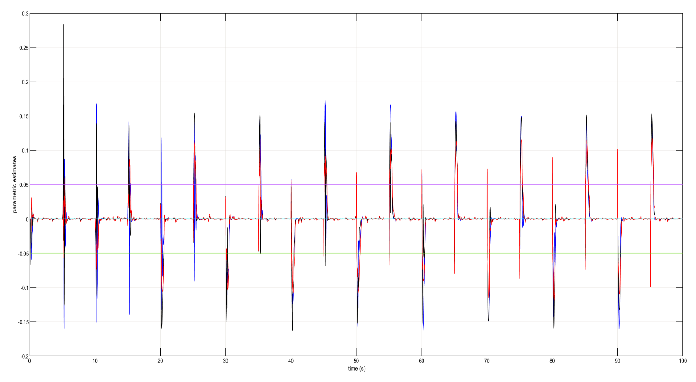

Table 1.
Norms and bounds of the error signals from the decentralized system for .
| Subsystem | ||||
|---|---|---|---|---|
| Roll motion | 24.1751 | 10.2967 | 39.4648 | 14.0219 |
| Pitch motion | 25.0046 | 10.2967 | 39.8284 | 14.0219 |
| Yaw motion | 12.8993 | 10.2965 | 15.7432 | 7.2366 |
Table 2.
Norms and bounds from the error signals for .
| Subsystem | ||||
|---|---|---|---|---|
| Roll motion | 24.3014 | 10.2966 | 70.7051 | 44.3231 |
| Pitch motion | 25.1058 | 10.2966 | 73.2932 | 44.3231 |
| Yaw motion | 12.9161 | 10.2965 | 20.4076 | 22.8841 |
Table 3.
Norms and bounds of the error signals for .
| Subsystem | ||||
|---|---|---|---|---|
| Roll motion | 24.2511 | 10.3014 | 5.7475 | 2.5669 |
| Pitch motion | 25.2279 | 10.3014 | 5.7229 | 2.5699 |
| Yaw motion | 12.9068 | 10.2965 | 2.3928 | 1.3212 |
Disclaimer/Publisher’s Note: The statements, opinions and data contained in all publications are solely those of the individual author(s) and contributor(s) and not of MDPI and/or the editor(s). MDPI and/or the editor(s) disclaim responsibility for any injury to people or property resulting from any ideas, methods, instructions or products referred to in the content. |
© 2024 by the authors. Licensee MDPI, Basel, Switzerland. This article is an open access article distributed under the terms and conditions of the Creative Commons Attribution (CC BY) license (http://creativecommons.org/licenses/by/4.0/).
Copyright: This open access article is published under a Creative Commons CC BY 4.0 license, which permit the free download, distribution, and reuse, provided that the author and preprint are cited in any reuse.


