Submitted:
27 December 2024
Posted:
27 December 2024
You are already at the latest version
Abstract
High entropy alloys are being increasingly investigated for their excellent combination of properties like strength, ductility, and significant low temperature fracture toughness. In the present work, the quinary equiatomic FeNiCoCrCu alloy is studied for its sputter deposition over a [001] nickel substrate using molecular dynamics simulations, described by the embedded atom method. The influence of annealing on the mechanical properties of the HEA coating is studied using nanoindentation with a virtual spherical indenter of diameter 25Å to an indentation depth of 25Å. The alloy is observed to undergo Transformation Induced Plasticity (TRIP) deformation – with activation and annihilation of stacking faults.
Keywords:
High Entropy Alloys
; Molecular Dynamics
; Sputter deposition
; Thin-Film coatings
; Mechanical coatings
1. Introduction
Alloying has been used to tailor material properties to suit several applications and service conditions. Predominantly alloying has been the addition of small amounts of secondary elements onto a principal element, however, this strategy restricts the combinatorial expanse of alloy design. High entropy alloys are a class of materials with five or more principal elements in equiatomic or near-equiatomic compositions [1,2]. More accurately called compositionally complex alloys, the crystallization of these alloys results in a solid solution rather than an alloy-intermetallic phase field. Additionally, the presence of multiple principal elements makes ascertaining specific solvent and solute phases near impossible.
In about two decades of research, single phase solid solution HEAs have been observed to conform to FCC, BCC, HCP, and orthorhombic structures [1]. Several of the properties of HEAs are attributed to the sluggish diffusion of the constituent atoms, micro/nano-twinning, and the severe lattice distortion by virtue of the multiple principal elements present. The latter results in a residual strain field present contributing to the strengthening of the alloy. Since realization, the Cantor alloy – Equiatomic FeMnCoCrNi, has been extensively studied for its mechanical properties and thermodynamics, crystallizing in a primary FCC and a secondary FCC+HCP phase-fields[3]. Subsequently, several such alloys were realized, with Cantor-like alloys garnering attention for their enhanced physical properties[1,4]. The lattice strain and low diffusivity, owing to the multiple principal elements, allow for a high hardness along with high strength and ductility [1,5], improving alloy design beyond the traditional strength-ductility tradeoff.
It has been observed that plasticity is mediated through TRIP in the dual phase Cantor alloy, with FCP↔HCP transformations resulting in enhanced ductility[6]. In this study, we analyse the characteristics of a thin film of the alloy at room temperature conditions. The FeNiCoCrCu, a modified Cantor alloy, hasn’t been studied extensively for its mechanical properties, to the knowledge of the authors. The mechanical properties of the Cantor alloy and the AlCoCrFeNi alloy serve as a good analogy and reference.[7]
Fang et. al. study the phase transformation and the evolution of dislocations in dual phase HEAs, in the dual-phase nanocrystalline FeMnCoCrNi alloy and report a 10% FCC phase in the HCP solid solution indicating the FCC to HCP and the reverse phase transformation which correlates to an increased plasticity in the HCP grains, the addition of HCP phase increases the ductility of the alloy. The AlCoCrCuFeNi alloy has a primary BCC phase and a secondary FCC phase and it’s hardness increases with increasing Al content [6,7]. The alloy’s mechanical response is also better with increasing Cr content [8]. The presence of Ni, Co and Cu stabilises the minor FCC phase in a largely BCC bulk stabilised by Al and Cr [9]. The BCC phase solid solution of alloy B has been reported to be of higher strength and hardness. Being the strongest BCC forming element, the larger atomic size of Al induces increased lattice distortion and hence strengthening [9]. Furthermore, the alloy has been reported to contain Ni-Al precipitates which contribute to the strengthening [10]. The less explored mechanical behaviour of the FeNiCoCrCu is hence an intriguing prospective study.
The onset of plasticity in nanostructures and the dislocation nucleation mechanisms in nanostructures, such as thin films, laminates, and composites, are studied primarily using nanoindentation [11,12], more so in the case of HEAs [13,14], as a way to better guage mechanical properties of films, nanocomposites and the origin of their mechanical behaviour. One of the most important advantages that nanoindentation tests offer is the measurement of film properties without removing the film from the substrate, and additionally it allows for the measurement of the spatial distribution of these properties across the sample bulk – lateral and depth directions.
Sputter deposition is a widely employed physical vapour deposition method for the fabrication of thin-films. Target atoms are ejected from a bulk sample in an inert environment by bombarding it with ions and the ejected atoms are directed towards a substrate either using external fields or with directed angles of ion-bombardment. Magnetron sputtering has been a primary sputtering technique used in fabricating HEA thin-films given the general nature of most of the transition metals in these alloys [14,15].
Given the laborious and delicate nature of the sputtering processes, the natural alternative to study HEAs (and most materials in general) is with computer experiments. In this study we employ classical molecular dynamics, an increasingly powerful tool to analyse the mechanism of these phenomena at an atomic scale. Classical MD simulations have been used in several areas of study and offer atomistic insights into simulated processes. MD simulations have been previously employed in the study of the mechanical properties of HEAs [16,17].
2. Materials and Methods
The large-scale Molecular Dynamics simulation code LAMMPS was used for the purpose of the simulation [18]. In the present study, two processes were simulated (i) Sputter Deposition and annealing of HEA thin-film (ii) Nanoindentation test. The interatomic interactions were defined using the tabulated Embedded Atom Method interatomic potential [19]. The EAM potential is a multi-particle interaction model developed by Daw and Baskes to describe pair-wise interactions in metals and alloys. The potential energy surfaces is defined as in Eq. 1.
Where Ei is the energy of atom i, F is the embedding energy function of the electronic density , ϕ is a pair potential and α and β are the element types of atoms i and j. The embedding term is responsible for describing the multi-body nature of the EAM potential. A nickel substrate is chosen so as to minimize lattice mismatch with the HEA coating. The lattice constants of bulk Ni and the FeNiCoCrCu alloys are 3.52 and 3.56 Ǻ respectively [19] resulting in a mismatch of 0.85%.
2.1. Sputter Deposition and Recrystallisation
A nickel substrate of size 100 Å x 100 Å x 90 Å and 82849 atoms was generated with a face centred cubic structure of lattice constant 3.52 Å. A Nose-Hoover thermostat was applied to the system at 300K. The simulation box is made non-periodic along the cartesian z axis and the deposition of the HEA is done by inserting equal amounts of the constituent elements. The atoms are sputtered with a thermal velocity along the negative z-axis in the range of 5-10Å /ps, onto the (001) face of the Ni substrate. The atoms were deposited at a rate of 1 atom per timestep, i.e., 1 atom per fs, and relaxed. The obtained as-deposited was subjected to the Ackland Jones structure analysis [20,21] using both the in-built functionality in LAMMPS and the open source post-processing tool Ovito [22] and the common neighbour analysis implemented in the latter. Based on the observed lack of long range ordering, the coating was then subjected to recrystallisation at 900K.
An average of 9300 atoms of each element (Fe, Co, Cr, Cu and Ni) were deposited for a coating around 70Å thick. A 10Å interface was provided between the substrate and the coating. The deposited atoms were inserted into the defined coating region at randomly chosen co-ordinates, which is in keeping with the alloy.
Prior works studied the heat treatment of the Cantor alloy with recrystallisation in the range of 600 to 900˚C [23,24,25,26,27], in analogy with the same, the film was heated to a temperature of 900 K (623ºC). The heating and cooling processes of the annealing were applied to the coating alone and not the substrate. The equilibrated atomic velocities at 300 K were scaled to 900 K, and a Nose-Hoover thermostat was applied. For the quenching process, a Nose-Hoover thermostat was set at 300 K on the coating layers for a specific time. The atomic coordinates were minimized at the end of each step in the process and were allowed to cool down to room temperature, essentially, an air-quenching of the coating was performed. The primary change applied here were to the soaking and cooling time of the recrystallization process. The coating sample was taken after removing the surface layer to achieve a good finish for the nanoindentation test. Three such specimen were generated to be analyzed by nanoindentation. Figure 1 shows the atomic snapshots of as-deposited, annealed, and specimen after removing the surface layers of the HEA film that is used for mechanical characterization using nanoindentation.
2.2. Nanoindentation
The generated specimen were subjected to nanoindentation by a virtual spherical indenter of diameter 25Å to an indent depth of 25Å. The indenter-particle interaction is defined by a repulsive force given by the following Eq. 2.
Where r is the distance between the atom and the indenter’s centre and R is the radius of the spherical indenter, and F(r) = 0 for r > R. The force constant K was given a value of 7.8904 eV/Å (100/xlat/xlat)[18] conforming to a virtual diamond indenter. The indenter was loaded onto the {001} plane of the alloy coating. The alloy coating and the 10Å interface were set to be mobile, and the remaining substrate was made rigid. The indenter was loaded and unloaded at five different velocities – 0.1, 0.2, 0.3, 0.4, and 0.5 Å/ps giving respective strain rates of 1.43 x 10⁹, 2.86 x 10⁹, 4.29 x 10⁹, 5.714 x 10⁹ and 7.413 x 10⁹ s-1 to ascertain the strain rate sensitivity of the alloy. Throughout the course of the nanoindentation, the dislocation extraction algorithm DXA [22,28] in Ovito was employed to study the evolution of dislocations.
3. Results and Discussion
3.1 Sputter Deposition
The simulated deposition of the alloy as described in Section 2.1, results in an amorphous thin-film seen through common neighbour analyses. The lack of immediate crystallization despite high incident velocities of the atoms is indicative of ineffective deposition, we hypothesize that the deposition being carried out on a low temperature substrate (300 K) prevents any significant rearrangement of the atoms. As such the obtained specimen are amorphous and of low density – poor crystallization and consolidation/cohesion of the film. This is in contrast to EB PVD of the alloy on heated substrates [29] where the alloy crystalized to a single FCC crystal, indicating the requirement of higher processing temperature(s).
3.2. Microstructural Investigations During Annealing: Effect of Annealing Time
The as-deposited thin film did not possess any discernible lattice ordering, as observed from both the common neighbor analysis and the Ackland-Jones analysis, as discussed earlier. To recover and recrystallize, the generated specimen were subjected to annealing. Upon annealing the thin film region at 900 ºC, the HEA crystal conformed with that of the nickel base and resulted in a predominantly FCC phase single crystal (Table 1 shows the structure composition of the mobile region). The present HCP phases in the alloy coating are stacking faults a few atomic layers thick.
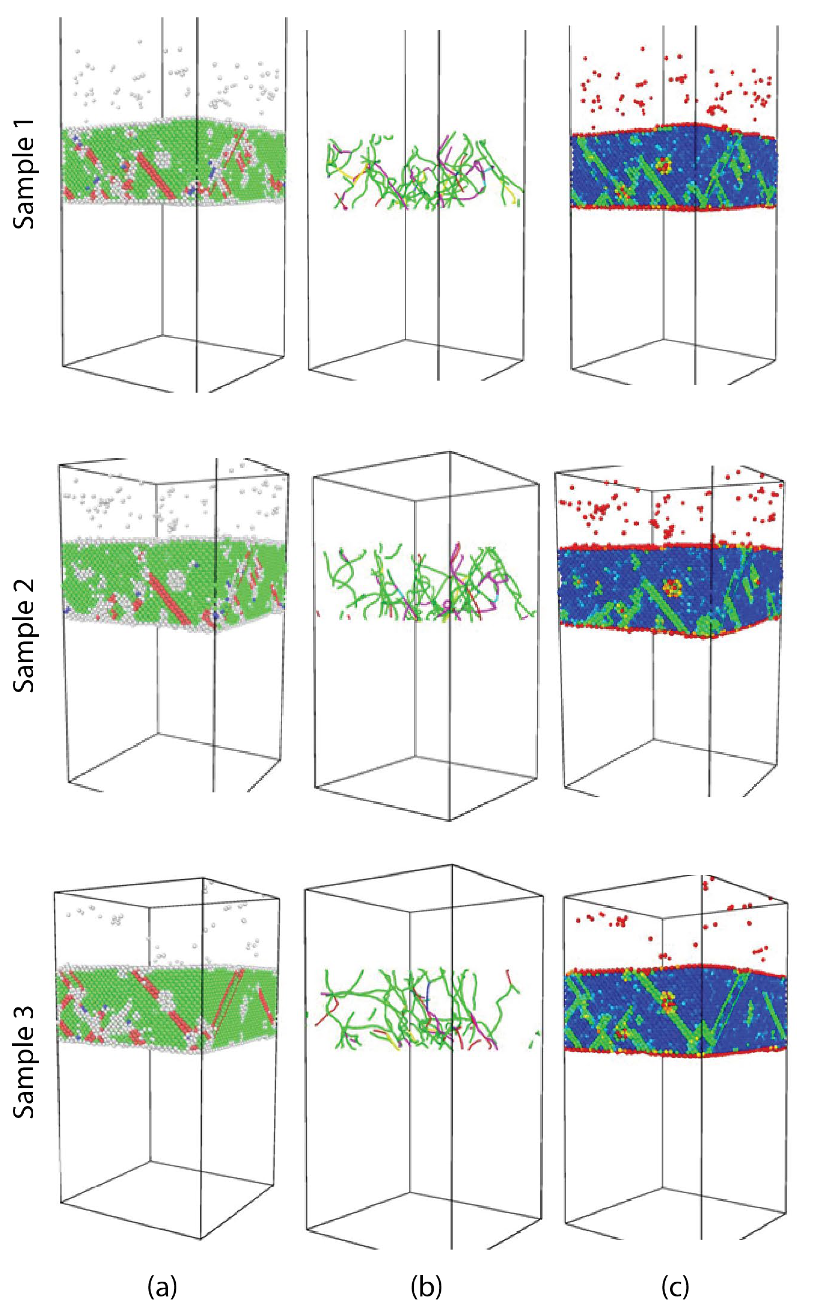
The HEA thin film specimen 1, 2, and 3 possess significantly high dislocation densities. Longer annealing times, allowing more time with increased mobility, allows relieving stresses and result in reduced dislocation densities. The CoCrFeNi system [30], the FeMnCoCr, and the Cantor alloy have also been observed to exhibit such stacking faults and annealing twins, i.e. a low stacking fault energy [31]. The dependence of SFE on the alloy composition and the valence electrons-atoms ratio, would indicate that the SFE of the FeCoCuCrNi HEA would be of the same order or lesser than these alloys. Confirming which the stacking faults were formed in the alloy despite the extreme kinetics of the quenching. Further, analogous alloys like the Al0.5CrCoFeCuNi and Al1.5CrCoFeCuNi have been observed to have negative SFE that decrease further with the addition Al [16]. Though annealed and force optimized, multiple voids of few atomic radii were present in all three specimen in the present study.
We see in Figure 3 that the stacking faults and dislocations present in the substrate play a role in the resulting microstructure of the film. We note that the stacking faults in the substrate near the interface extend into the HEA film, indicating the influence of the local crystal structure when the thin film crystallizes. Combined with the low stacking fault energy of the alloy, through the course of annealing, we see that these faults persist, indicating a highly unstable fault energy (barrier to the stacking fault). We see this observation irrespective of varying annealing parameters.
The pre-existing faults act as nucleating sites for the faults in the deposited thin film this observation is further supported by the extension of the stacking fault with longer soaking times as seen in Figure 3.
Figure 4.
Microstructure evolution with respect to different annealing parameters – different specimen (parameters detailed in Table 1. (a) Crystal structure based on CNA (green – FCC, red – HCP, blue – BCC and white – amorphous), (b) Dislocations and (c) Centrosymmetry parameter distribution.
Figure 4.
Microstructure evolution with respect to different annealing parameters – different specimen (parameters detailed in Table 1. (a) Crystal structure based on CNA (green – FCC, red – HCP, blue – BCC and white – amorphous), (b) Dislocations and (c) Centrosymmetry parameter distribution.
3.2. Load-Displacement Behavior: Annealing Time and Strain-Rate Effects
The yielding and the onset of plasticity in the thin-film can be observed in the load-displacement plots as a pop-in or a dip in the load response (Figure 5). The yielding load does not change with a particular trend with respect to the annealing conditions. In comparison with the dual phase cantor alloy – increased HCP phase fraction translates to an improved yield strength[6]. Other than the case of specimen 1, the yielding load decreases with increasing strain-rates, however the response for the highest of the applied strain rates does not suit this trend. Throughout the different strain rates, the specimen yielded in the range of 80-90 nN, however no specific trend is discernible with respect to the annealing time. Though the yielding loads were similar, the indent depths required to induce yield or plasticity increased with increasing strain-rate.
The formed SFs dissolve into the FCC solid solution after loading. The plasticity is evidently mediated by the transformation of the present phases into FCC, i.e. annihilation of Shockley partials, along with the generally observed twinning i.e. nucleation of a twinning partial and dislocation motion. On the other hand, the maximum load experienced by the film samples increases with increasing annealing time or the phase composition of the alloy (%FCC). These results are in sharp contrast with the deformation behaviour of the two-phase Cantor alloy system, wherein the alloy with the lower FCC content had increased plasticity[6].
3.3. Microstructures After Indentation
After indentation (Figure 7), the specimen had a reduced dislocation density and an increased FCC fraction. In specimen 2 and 3, the other phases present diminished into the FCC structure, however, in the case of sample 1, the trace amounts of BCC and the other phases rearrange resulting in a 10.5% HCP (increased HCP fraction) and a 81.4% FCC structure (increased). (Figure 6) i.e. three phase transformations could be said to occur, HCP → FCC, BCC → FCC and BCC → HCP, the latter was observable only in specimen 1. i.e. local plastic flow is mediated by phase transformation as observed in the Cantor and several other Cantor-like alloys [5,16,32,33]. The dense dislocation bin generally observed around the indent pit in nanoindentation studies, is not observed, nevertheless the decreased dislocation density is comparable with that reported for the cantor alloy [34]. Also, as reported by Zhang et al the thin film has arrested or pinned dislocations [35].
Very few dislocation loops were present in the film, unlike the of the Cantor alloy, though not of the same magnitude/lengths. At the loaded states (Figure 7), the dislocation density of the FeCoCrCuNi alloy sample 1 was higher than that of the Cantor alloy [34]. However specimen 2 and 3 had lower dislocation densities (Figure 6), as their initial dislocation densities were drastically lesser than that of sample 1. As is the nature of the characterization method, the Ni substrate and its dislocations remain unchanged while the defects in the film evolve.
Unlike the AlCoCrCuFeNi HEA, the alloy is homogenous and does not result in the formation of phases rich in elemental components or lesser alloy systems, nor did the deformation cause the same [36]. The plastic zone of the alloy is continually dominated by Shockley partials, as seen in Figure 5, like most FCC systems and the Cantor alloy[34]. However, it is also important to note that the CrCoNi medium entropy alloy, has a higher yield strength.
During the plastic deformation, the voids present in the thin film, act as sources of dislocations. The applied deformation resulted in the reduction of several of the voids initially present, and the reduction of their volumes, similar to the results reported for the Cantor alloy [32,37] p. 20. The observations of Lin et al, of the deformation of the FeCoCrNi HEA and the TWIP mechanism wherein the phase transformation occurring is FCC -> HCP [38]. In this specific context, the presence of Cu stabilizes the FCC phase, enhancing the plasticity.
One interesting aspect is that the phase transformations observed in the alloy thin film continued for a few picoseconds even after the indent load was removed. This could be attributed to the renormalization of the stresses and the diminished diffusivity, a characteristic of high entropy alloys. While a study of the diffusion behavior of a few High entropy alloys concluded that the sluggish diffusion is an effect of the presence of Mn in the system and not conclusively because of the number of elements present [39], the effect of Cu on the diffusion has not been explored so far and presents an interesting future prospect in understanding the mechanical properties of HEAs.
4. Conclusions
We demonstrate the sputter deposition of the FeNiCoCrCu HEA. We discover that a simple and straightforward deposition along the z axis with a velocity distribution applied on the sputtered atoms, results in an amorphous thin film of the alloy. As the alloy is known to crystalize as an FCC single crystal the deposited film is then annealed at 900K at different soaking times and subsequently cooled at different rates. As such the effect of the annealing parameters on the mechanical properties of the alloy are explored. We conclude that apart from slightly better structural conformations, longer soaking times for annealing does not systematically affect the mechanical properties. Annealing the films to allow for recrystallization and drive the formation of the single-phase FCC, we obtain films that conform with the FCC and more so with the defects present at and near the substrate interface. However, we do observe that the alloy exhibits the TRIP behavior with predominantly the annihilation of stacking faults, upon applying the indentation load. With the described alloy, we hence see transitions from other phases to the FCC upon deformation. As expected, we also see that the defects and voids act as stress concentration sites and nucleate dislocations. More studies are needed into optimizing the deposition parameters to obtain the FCC crystal from the get-go. Further, the effect of composition on the mechanical properties of this alloy is another potential avenue yet to be explored and would enable better alloy design.
Supplementary Materials
Not Applicable.
Author Contributions
Conceptualization, methodology, SA and VK.; software, validation, formal analysis, investigation, resources, data curation, SA; writing—original draft preparation, SA; writing—review and editing, VK, NY; visualization, SA, NY and VK; supervision, NY and VK; All authors have read and agreed to the published version of the manuscript.”.
Funding
This research received no external funding.
Institutional Review Board Statement
Not applicable.
Informed Consent Statement
Not applicable.
Data Availability Statement
Dataset available on request from the authors.
Acknowledgments
Not Applicable.
Conflicts of Interest
The authors declare no conflicts of interest.
References
- EP. George, D. Raabe, and R. O. Ritchie. “High-entropy alloys. Nat. Rev. Mater., 2019, 4, 515–534. [Google Scholar] [CrossRef]
- JW. Yeh. et al., “Nanostructured high-entropy alloys with multiple principal elements: Novel alloy design concepts and outcomes. Adv. Eng. Mater., 2004, 6, 299–303. [Google Scholar] [CrossRef]
- BCantor, I. T. H. Chang, P. Knight, and A. J. B. Vincent, Microstructural development in equiatomic multicomponent alloys. Mater. Sci. Eng. -Struct. Mater. Prop. Microstruct. Process., 2004, 375, 213–218. [Google Scholar] [CrossRef]
- Kumar and, M. Gupta, An Insight into Evolution of Light Weight High Entropy Alloys: A Review. Metals 2016. [Google Scholar] [CrossRef]
- ZLi, K. G. Pradeep, Y. Deng, D. Raabe, and C. C. Tasan. Metastable high-entropy dual-phase alloys overcome the strength–ductility trade-off. Nature, 2016, 534, 227–230. [Google Scholar] [CrossRef]
- Q Fang. et al., Probing the phase transformation and dislocation evolution in dual-phase high-entropy alloys. Int. J. Plast., 2019, 114, 161–173. [Google Scholar] [CrossRef]
- J. Tong et al., Mechanical performance of the AlxCoCrCuFeNi high-entropy alloy system with multiprincipal elements. in Metallurgical and Materials Transactions A: Physical Metallurgy and Materials Science, Minerals, Metals and Materials Society, 2005, 1263–1271. [CrossRef]
- TT. Shun and W. J. Hung. Effects of Cr Content on Microstructure and Mechanical Properties of AlCoCrxFeNi High-Entropy Alloy. Adv. Mater. Sci. Eng., 2018, 2018. [Google Scholar] [CrossRef]
- CTung, J. W. Yeh, T. tsung Shun, S. K. Chen, Y. S. Huang, and H. C. Chen. , On the elemental effect of AlCoCrCuFeNi high-entropy alloy system. Mater. Lett., 2007, 61, 1–5. [Google Scholar] [CrossRef]
- YP. Wang, B. S. Li, and H. Z. Fu. , Solid solution or intermetallics in a high-entropy alloy. Adv. Eng. Mater., 2009, 11, 641–644. [Google Scholar] [CrossRef]
- SSuresh, T.-G. Nieh, and B. W. Choi. , Nano-indentation of copper thin films on silicon substrates. Scr. Mater., 1999, 41, 951–957. [Google Scholar] [CrossRef]
- FBahr, D. E. Kramer, and W. W. Gerberich. , Non-linear deformation mechanisms during nanoindentation. Acta Mater., 1998, 46, 3605–3617. [Google Scholar] [CrossRef]
- Wu, J. S. C. Jang, and T. G. Nieh. Elastic and plastic deformations in a high entropy alloy investigated using a nanoindentation method. Intermetallics, 2016, 68, 118–127. [Google Scholar] [CrossRef]
- S-Y. Lin, S.-Y. Chang, C.-J. Chang, and Y.-C. Huang. , Nanomechanical Properties and Deformation Behaviors of Multi-Component (AlCrTaTiZr)NxSiy High-Entropy Coatings. Entropy, 2013, 16, 405–417. [Google Scholar] [CrossRef]
- W-B. Liao. et al., High Strength and Deformation Mechanisms of Al0.3CoCrFeNi High-Entropy Alloy Thin Films Fabricated by Magnetron Sputtering. Entropy, 2019, 21, 146–146. [Google Scholar] [CrossRef] [PubMed]
- MBahramyan, R. T. Mousavian, and D. Brabazon. , Study of the plastic deformation mechanism of TRIP–TWIP high entropy alloys at the atomic level. Int. J. Plast., 2020, 127, 102649–102649. [Google Scholar] [CrossRef]
- WM. Choi, Y. H. Jo, S. S. Sohn, S. Lee, and B. J. Lee. Understanding the physical metallurgy of the CoCrFeMnNi high-entropy alloy: An atomistic simulation study. Npj Comput. Mater., 2018, 4, 1–9. [Google Scholar] [CrossRef]
- S Plimpton. , Fast parallel algorithms for short-range molecular dynamics. J. Comput. Phys., 1995, 117, 1–19. [Google Scholar] [CrossRef]
- D Farkas and A. Caro. Model interatomic potentials and lattice strain in a high-entropy alloy. J. Mater. Res., 2018, 33, 3218–3225. [Google Scholar] [CrossRef]
- J Ackland and A. P. Jones. Applications of local crystal structure measures in experiment and simulation. Phys. Rev. B - Condens. Matter Mater. Phys., 2006, 73, 054104–054104. [Google Scholar] [CrossRef]
- J Ackland, M. I. Mendelev, D. J. Srolovitz, S. Han, and A. V. Barashev. , Development of an interatomic potential for phosphorus impurities in α-iron. J. Phys. Condens. Matter, 2004, 16, S2629–S2629. [Google Scholar] [CrossRef]
- Stukowski, Visualization and analysis of atomistic simulation data with OVITO-the Open Visualization Tool. Model. Simul. Mater. Sci. Eng., 2010, 18, 015012–015012. [CrossRef]
- Shahmir, J. He, Z. Lu, M. Kawasaki, and T. G. Langdon. Effect of annealing on mechanical properties of a nanocrystalline CoCrFeNiMn high-entropy alloy processed by high-pressure torsion, Elsevier 2016, 676, 303. [CrossRef]
- N D. Stepanov, N. Y. Yurchenko, M. A. Tikhonovsky, and G. A. . Salishchev, Effect of carbon content and annealing on structure and hardness of the CoCrFeNiMn-based high entropy alloys. J. Alloys Compd., 2016, 687, 59–71. [Google Scholar] [CrossRef]
- N D. Stepanov, D. G. Shaysultanov, M. S. Ozerov, S. V. Zherebtsov, and G. A. Salishchev, Second phase formation in the CoCrFeNiMn high entropy alloy after recrystallization annealing. Mater. Lett., 2016, 185, 1–4. [Google Scholar] [CrossRef]
- F Otto. et al., Decomposition of the single-phase high-entropy alloy CrMnFeCoNi after prolonged anneals at intermediate temperatures. Acta Mater., 2016, 112, 40–52. [Google Scholar] [CrossRef]
- P P. Bhattacharjee. et al., Microstructure and texture evolution during annealing of equiatomic CoCrFeMnNi high-entropy alloy. J. Alloys Compd., 2014, 587, 544–552. [Google Scholar] [CrossRef]
- Stukowski and, K. Albe. , Extracting dislocations and non-dislocation crystal defects from atomistic simulation data. Model. Simul. Mater. Sci. Eng., 2010, 18, 085001–085001. [Google Scholar] [CrossRef]
- I Ustinov, S. A. Demchenkov, T. V. Melnychenko, V. S. Skorodzievskii, and S. S. Polishchuk. , Effect of structure of high entropy CrFeCoNiCu alloys produced by EB PVD on their strength and dissipative properties. J. Alloys Compd., 2021, 887, 161408. [Google Scholar] [CrossRef]
- F He. et al., Solid solubility, precipitates, and stacking fault energy of micro-alloyed CoCrFeNi high entropy alloys. J. Alloys Compd., 2018, 769, 490–502. [Google Scholar] [CrossRef]
- J Zaddach, C. Niu, C. C. Koch, and D. L. Irving. , Mechanical Properties and Stacking Fault Energies of NiFeCrCoMn High-Entropy Alloy. JOM, 2013, 65, 1780–1789. [Google Scholar] [CrossRef]
- S Chen. et al., Real-time observations of TRIP-induced ultrahigh strain hardening in a dual-phase CrMnFeCoNi high-entropy alloy. Nat. Commun., 2020, 11, 826–826. [Google Scholar] [CrossRef] [PubMed]
- S Sinha. et al., Nanoindentation behavior of high entropy alloys with transformation-induced plasticity. Sci. Rep., 2019, 9, 1–11. [Google Scholar] [CrossRef]
- Alabd Alhafez, C. J. Ruestes, E. M. Bringa. , Nanoindentation into a high-entropy alloy – An atomistic study. J. Alloys Compd., 2019, 803, 618–624. [Google Scholar] [CrossRef]
- Zhang, J. Han, J. Meng, B. Su, and P. Li, Rapid preparation of AlCoCrFeNi high entropy alloy by spark plasma sintering from elemental powder mixture. Mater. Lett., 2016, 181, 82–85. [Google Scholar] [CrossRef]
- D G. Shaysultanov, N. Stepanov, A. V. Kuznetsov, G. A. Salishchev, and O. N. Senkov. G. Shaysultanov, N. Stepanov, A. V. Kuznetsov, G. A. Salishchev, and O. N. Senkov, Phase Composition and Superplastic Behavior of a Wrought AlCoCrCuFeNi High-Entropy Alloy. JOM, 2013, 65, 1815–1828. [Google Scholar] [CrossRef]
- Y Qi, X. Chen, and M. Feng. , Molecular dynamics-based analysis of the effect of voids and HCP-Phase inclusion on deformation of single-crystal CoCrFeMnNi high-entropy alloy. Mater. Sci. Eng. A, 2020, 791, 139444–139444. [Google Scholar] [CrossRef]
- Q Lin, J. Liu, X. An, H. Wang, Y. Zhang, and X. Liao. , Cryogenic-deformation-induced phase transformation in an FeCoCrNi high-entropy alloy. Mater. Res. Lett., 2018, 6, 236–243. [Google Scholar] [CrossRef]
- Dąbrowa. , Demystifying the sluggish diffusion effect in high entropy alloys. J. Alloys Compd., 2019, 783, 193–207. [Google Scholar] [CrossRef]
Figure 1.
Snapshots of the (a) as-deposited sample (b) the sample after annealing and (c) sample after removing the surface layers of the HEA film for mechanical characterization. A 70Å thick.
Figure 1.
Snapshots of the (a) as-deposited sample (b) the sample after annealing and (c) sample after removing the surface layers of the HEA film for mechanical characterization. A 70Å thick.
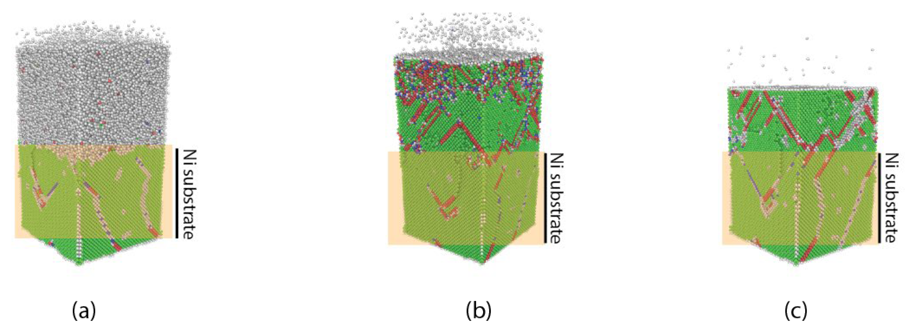
Figure 2.
Schematic illustration of the annealing cycles for each of the specimen.

Figure 3.
Evolution of the microsstructure of the substrate and film at (a) before deposition, (b) the end of deposition (c) during the annealing steps (d) after annealing, in specimen 3.
Figure 3.
Evolution of the microsstructure of the substrate and film at (a) before deposition, (b) the end of deposition (c) during the annealing steps (d) after annealing, in specimen 3.
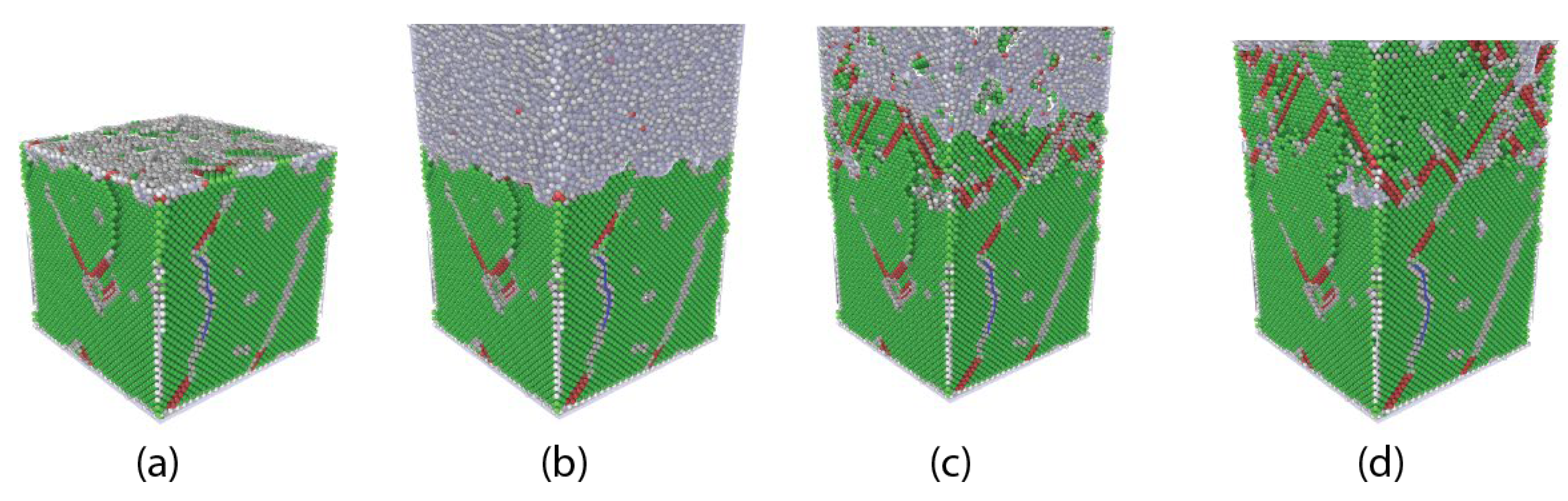
Figure 5.
Load-displacement curves for different specimen (a) specimen-1 (b)specimen- 2 and (c) specimen-3, at different strain rates.
Figure 5.
Load-displacement curves for different specimen (a) specimen-1 (b)specimen- 2 and (c) specimen-3, at different strain rates.
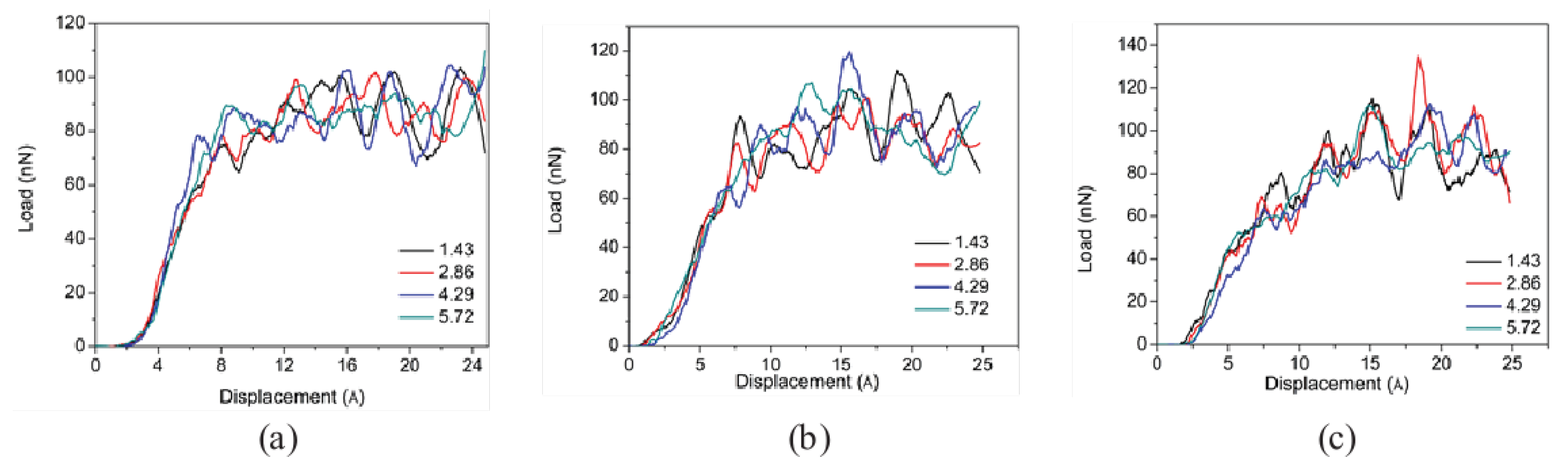
Figure 6.
Local crystal ordering in the three specimen at Yield point and at full indent.
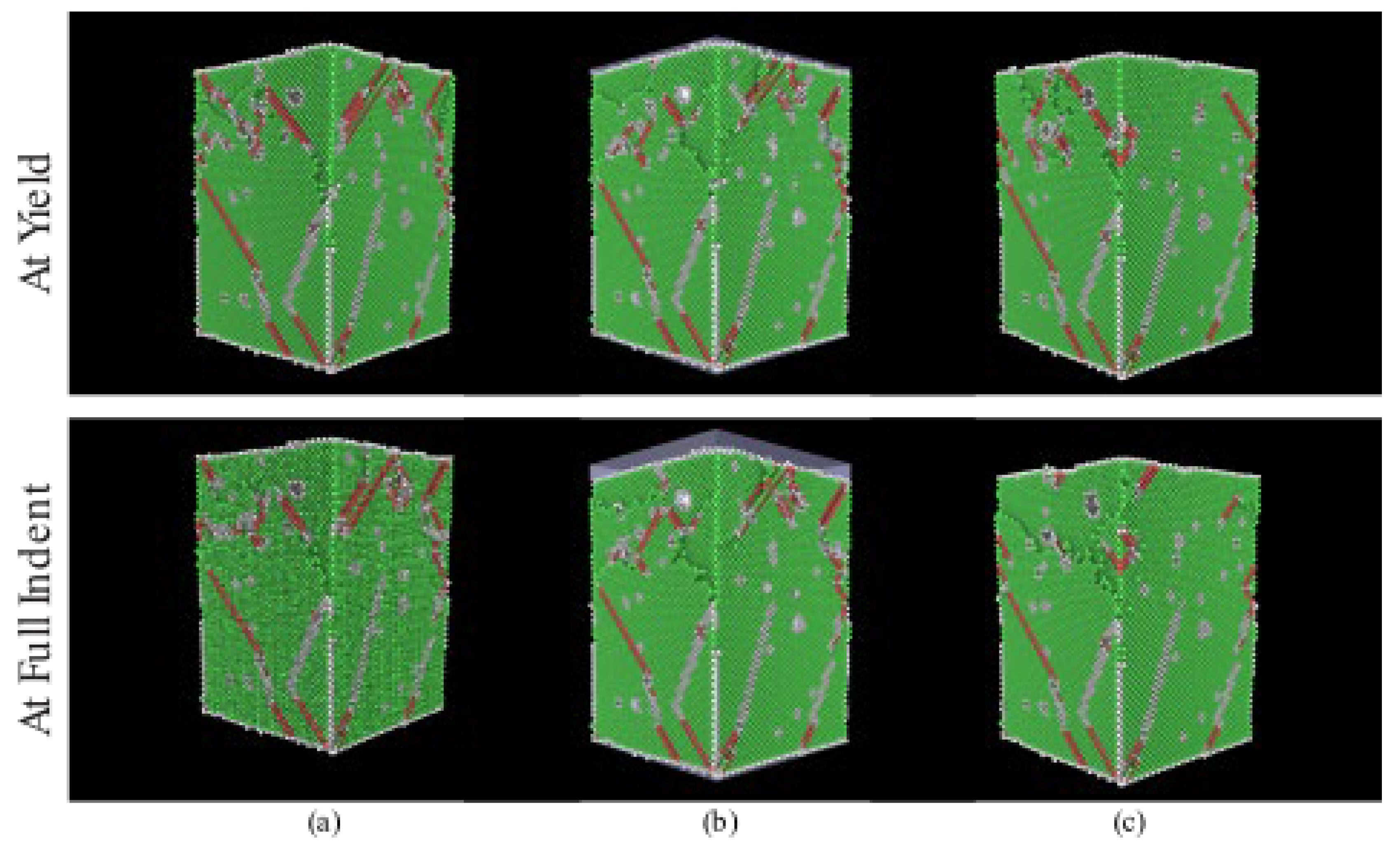
Figure 7.
Partial dislocations in the annealed thin-film specimen at yield point as seen in Figure 4 and at full indent in different specimen (a) specimen-1, (b)specimen- 2 and (c) specimen-3.
Figure 7.
Partial dislocations in the annealed thin-film specimen at yield point as seen in Figure 4 and at full indent in different specimen (a) specimen-1, (b)specimen- 2 and (c) specimen-3.
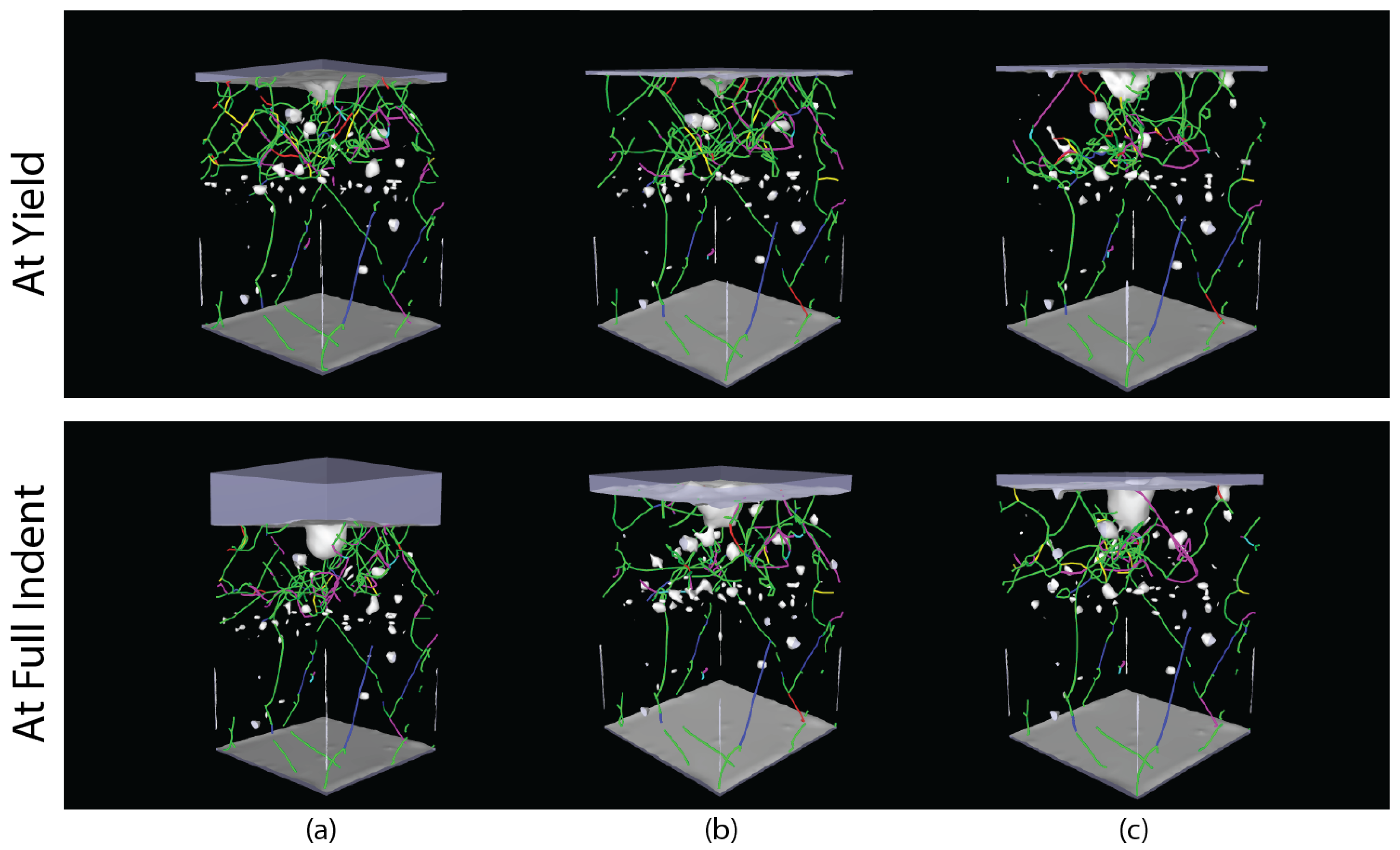

Table 1.
Effect of soaking and cooling times on the crystal structures and dislocation density in the coated thin films.
Table 1.
Effect of soaking and cooling times on the crystal structures and dislocation density in the coated thin films.
| Specimen | Annealing soaking time (ps) | Cooling time (ps) | % FCC | %HCP | Dislocation density (1017 m-2) |
|---|---|---|---|---|---|
| 1 | 20 | 50 | 79.5 | 10.1 | 5.051 |
| 2 | 20 | 60 | 80.9 | 9.1 | 4.740 |
| 3 | 30 | 70 | 81.6 | 8.8 | 4.065 |
Disclaimer/Publisher’s Note: The statements, opinions and data contained in all publications are solely those of the individual author(s) and contributor(s) and not of MDPI and/or the editor(s). MDPI and/or the editor(s) disclaim responsibility for any injury to people or property resulting from any ideas, methods, instructions or products referred to in the content. |
© 2024 by the authors. Licensee MDPI, Basel, Switzerland. This article is an open access article distributed under the terms and conditions of the Creative Commons Attribution (CC BY) license (http://creativecommons.org/licenses/by/4.0/).
Copyright: This open access article is published under a Creative Commons CC BY 4.0 license, which permit the free download, distribution, and reuse, provided that the author and preprint are cited in any reuse.


