1. Introduction
In machining, numerical control, also known as Computer Numerical Control (CNC) refers to the automated control of tools using a computer.
CNC is a manufacturing method that uses preprogrammed computer software to automate the operation, movement, and precision of machine tools. This software is integrated into machinery. It can automate the functions of various cutting tools, including mills, lathes, routers, drills, grinders, water jets, and lasers.
The optimization of G-code for machining time is a critical aspect of enhancing the efficiency and performance of CNC (Computer Numerical Control) machining processes.
This paper presents an optimization of machining time resulting from variations in speed, feed rate, and tool path strategy. Advanced Computer Aided Manufacturing (CAM) software can enhance tool path strategies to boost both efficiency and quality. Through optimization, machining time can be shortened, surface finish improved, and tool wear reduced. The machining time of each variation was obtained by simulation using CAM software and CNC simulation software. CAM software makes it possible to achieve and simulate manufacturing processes to check the correctness of a project before it is implemented [
1].
The machining strategy affects the overall machining time [
2]. The implementation and selection of cutting path strategies with appropriate cutting parameters have significant effect on surface [
3]. Nowadays, programmable automated CNC machine tools rely upon CAM software as opposed to manual programs. This has led to a decrease in program time requirements, coupled with a reduction in the potential for human error [
4].
In the world of CNC machining, achieving optimal performance in terms of precision, efficiency, and cost-effectiveness is essential for modern manufacturing. One of the critical factors driving this optimization is the toolpath strategy, which refers to the pre-programmed route the cutting tool follows to shape a workpiece. The toolpath strategy is a methodology developed to address the complexities of toolpath generation, with a focus on improving machining processes across different materials and machine configurations.
The tool path strategy emphasizes the importance of efficient tool movement, minimized cycle times, reduced tool wear, and superior surface finishes. By leveraging advanced algorithms and optimization techniques, the strategy ensures that tools move in the most effective and economical way, without compromising on accuracy or quality [
5]. With the rise of advanced CNC systems and the increasing demand for high-precision, low-waste manufacturing, the tool path strategy has become a cornerstone of modern CNC programming [
6].
The primary goal of toolpath is to optimize the entire machining process from minimizing the path distance to enhancing material removal rates, thereby increasing overall productivity and reducing costs. This strategy is particularly valuable for industries such as aerospace, automotive, and medical device manufacturing, where the precision of each part is paramount [
7]. Furthermore, with the continuous advancement of CNC technology, the tool path strategy is evolving to incorporate real-time machine feedback and adaptive learning algorithms, ensuring even greater levels of optimization and performance [
8].
The structure of this paper is as follows:
Section 2 presents an overview of research on toolpath planning on CNC machine performance about time-efficient machining.
Section 3 introduces the materials and methods used of different toolpath strategies and their effect on machining time during the processing.
Section 4 reports the obtained results of three projects that have been considered in the analysis.
Section 5 covers the discussion of data collected from both simulation results of the CNC program and real-time CNC operations. Finally,
Section 6 summarizes our conclusions.
2. Related Work
Nowadays, programmable automated CNC machine tools rely upon CAM software as opposed to manual programs. This has led to a decrease in program time requirements, coupled with a reduction in the potential for human error [
9].
In general, tool path generation methods must be selected from the set of ordinary toolpath options available, for example, Zig Zag, Radial, Zig, and Spiral toolpaths [
10]. The significant benefits associated with CNC machining are that it can ensure high machining accuracy through simple programming, as well as repeatability in complex parts machining [
11].
In the fast-paced world of CNC machining, the toolpath strategy is a critical approach to optimizing toolpath generation, enhancing machining efficiency, and ensuring precision. Whether used in metalworking, plastic fabrication, or other materials, optimizing toolpaths can yield significant improvements in production time, cost efficiency, and part quality. Below are the key benefits of employing a toolpath strategy in CNC machining.
2.1. Improved Precision and Accuracy
An optimized tool path strategy ensures that the CNC machine follows the most efficient and precise route to shape a part. By minimizing unnecessary movements and ensuring accurate tool engagements, the risk of dimensional errors is significantly reduced [
12]. This is especially crucial for industries requiring high-precision components such as aerospace and medical device manufacturing.
2.2. Reduced Cycle Times and Increased Productivity
By reducing idle movements and avoiding unnecessary tool changes, an optimized tool path can lead to much shorter cycle times. This means more parts can be produced in less time, driving higher throughput in a factory setting [
13]. The time saved from optimizing the path directly contributes to better resource utilization and increased production capacity.
2.3. Extended Tool Life and Reduced Wear
A key benefit of the tool path strategy is its ability to reduce tool wear. By selecting optimal cutting paths and strategies such as controlling cutting speeds, feed rates, and depths of cut the tool is exposed to less stress and strain, which leads to longer tool life [
14]. This reduces the frequency of tool replacements, saving costs on consumables.
2.4. Improved Surface Finish and Quality
Using an efficient tool path strategy results in smoother, more accurate cuts, which directly contributes to better surface finishes. Fewer adjustments and corrections are needed by post machining, which minimizes the need for secondary operations such as polishing or deburring [
15]. For industries producing high-quality components, this benefit is especially important.
2.5. Material and Cost Efficiency
The tool path strategy can help reduce material waste by ensuring that the tool path is optimized for minimal cutting airtime and waste. Whether it’s improving the nesting of parts on a sheet of metal or efficiently removing material from a block, the toolpath can maximize material usage while keeping costs down [
16]. This leads to a more sustainable production process.
2.6. Risk Reduction and Safety
A well-designed tool path strategy reduces the chances of machine crashes, tool collisions, or workpiece damage. By simulating the toolpath before physical machining begins, operators can identify and correct any potential problems [
17]. This not only saves time and money but also improves safety in the workshop environment.
2.7. Flexibility Across Materials and Applications
One of the significant advantages of an effective tool path strategy is its adaptability to different materials. Whether working with metals, plastics, or composites, the tool path can be adjusted to optimize machining parameters based on the material's specific properties, ensuring optimal cutting conditions [
18].
From the theoretical frameworks for toolpath generation, several aspects from the literature on CAM software algorithms can be considered:
2.8. Freeform Features Recognition
In complex geometries, freeform feature recognition algorithms play a crucial role in automatically generating toolpaths. These algorithms analyze part geometry and suggest machining strategies that minimize tool wear and machining time, a feature applicable to industrial CAM tools like ICAM3D. Discussing how ICAM3D incorporates such algorithms can provide deeper insights into its adaptability and automation capabilities [
19].
2.9. 3. D Model-Based Toolpath Generation
Contemporary methods incorporate 3D point cloud data to design toolpaths dynamically, a practice that significantly enhances precision and adaptability for intricate components. Exploring whether ICAM3D employs similar data-driven methodologies can underline its technological robustness [
20].
2.10. Adaptive Algorithms for Efficiency
Many CAM software algorithms now include adaptive techniques that modify toolpaths in real-time based on factors like material properties and cutting dynamics. Highlighting ICAM3D's position regarding adaptive machining strategies could add value to the study.
Optimizing toolpath planning plays a vital role in enhancing the overall efficiency of CNC machines, especially when prioritizing time-efficient machining. This study explores the assessment of various toolpath strategies and their impact on machining time when processing projects with differing levels of geometric complexity.
3. Materials and Methods
This study utilizes simulation and optimization methods to analyse machining processes. It involves using CAM and CNC simulation software to analyse program efficiency and machining time. ICAM3D software is utilized to create CNC programs by defining parameters such as speed and toolpath strategy based on the workpiece's cross-sectional variations.
3.1. Description of Toolpath Strategies
In this paper, we used four toolpath strategies, which have been described below.
In the Spiral In strategy, the tool starts at the outer edge of the pocket or shape and gradually moves inward in a spiral pattern toward the centre. This toolpath is typically used for pocket milling, engraving, or contouring tasks where the cutting tool needs to remove material in a smooth, continuous manner.
Equation for Spiral In for TP1, is described as follows:
Where:
The Spiral Out strategy for TP2 is the reverse of the Spiral In. The tool begins at the centre of the pocket or shape and spirals outward toward the perimeter. This method is often used when the goal is to start from the centre and work outward, such as in engraving or shallow pocketing operations.
Equations for strategies spiral Out for TP2, are described as follows:
Where:
In the One Way strategy for TP3, the cutting tool moves in a single direction along the workpiece, typically following a linear path. This toolpath is most used for simple pocketing or contouring tasks and is characterized by tool movement in one direction (either left to right or right to left) for each pass, followed by retraction and a new pass in the same direction.
With 20 flutes, the tool engages with the material at multiple points simultaneously. The cutting path for one pass is determined by flute spacing with equation:
Where:
Seffective = s/20 - Reduced step-overdue to 20 flutes
x0, y0 – Start position
n – Number of passes in X
i – Number of steps in Y.
The Zig Zag toolpath for TP4, also known as back-and-forth milling, alternates between two directions (left to right and right to left), creating a zig-zag pattern. This strategy is often used for pocket milling, profile cuts, and other operations where the material removal needs to be uniform and fast.
In a Zig-Zag strategy for TP4, the tool alternates directions, and the 20 flutes reduce the effective cutting step-over distance. The equation becomes:
Where:
Seffective=s/20 – Reduced step-over distance for the 20 flutes
x0, y0 - Starting position
w – Pocket width (adjusted for tool diameter)
n – Zig Zag pass number
i – Row index (alternating directions with (-1)^i.
With 20 flutes, the tool maximizes material removal efficiency while maintaining high cutting accuracy.
Material Removal Rate (MRR) for each strategy, we need to consider the following formulas:
and,
Where:
f – Total feed rate (mm/min)
ft – Feed per tooth (mm/tooth)
N – Number of teeth (flutes) on the tool
D – Diameter of the tool (mm)
W – Width of cut or step-over (mm)
DOC – Depth of cut (mm).
3.2. Description of Projects
The first project, titled P1, is a square geometry with dimensions of 1200 x 900 mm. The material used is natural stone. The stone was processed using the T0050 tool, with the pocketing procedure performed at a depth of 3 mm in a single step. Project P1 was completed using four toolpath strategies, labelled TP1 (Toolpath Strategy 1) through TP4 (Toolpath Strategy 4). The results are presented in a table, and the time required to complete the project is provided in minutes.
In the second project, titled P2, the geometry is a square with dimensions of 1600 x 750 mm. The material used is natural stone, and the pocketing procedure was carried out with the T0050 tool at a depth of 2 mm. The work process is the same as in the P1 project, and the same tool has been used. The simulation of the project was performed using ICAM 3D software.
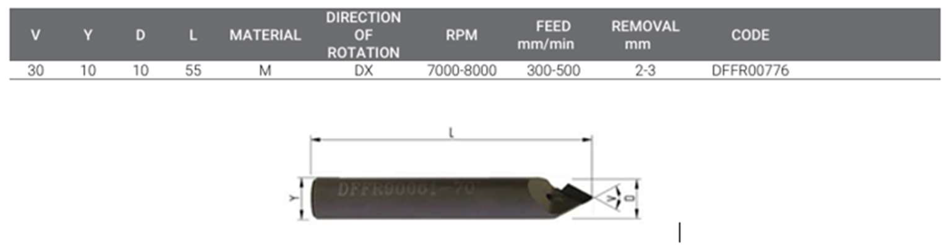
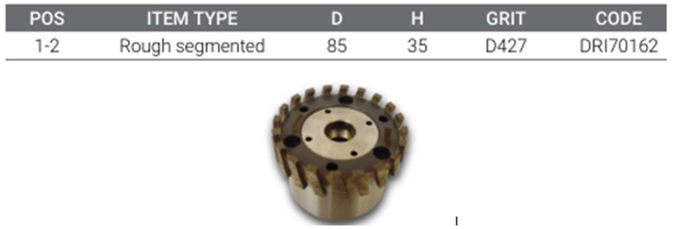
In the third project, titled P3, a 100x50 square geometry trench has been studied. The trench was finished in natural stone material using the side of the T503 tool at a depth of 2 mm in a single pass. The plowing was performed with four different toolpath strategies, labelled TP1 to TP4. The simulation was conducted using ICAM 3D software, and the final product was created with the Intermac Master 33.3 CNC. The results are presented on a table, showing the time required to complete the work with each of the four strategies, given in minutes. The tools used for the study are described in the following figures.
In
Figure 1 and
Figure 2, the tools used to complete the work with the four toolpath strategies have been presented. The tool shown in the first picture, T503, has been used in the third project to complete the trench. The tool shown in the second picture, T0050, has been used for the first two projects, titled P1 and P2.
For the analysis of the work, an Intermac Master 33.3 CNC machine has been used. Three projects were considered in the analysis. For the first two projects, the simulation has been performed using the T0050 tool. In the third project (P3), the simulation has been done with the T503 tool.
The
Table 1 presents the geometry of the projects as well as the tools used for each geometry.
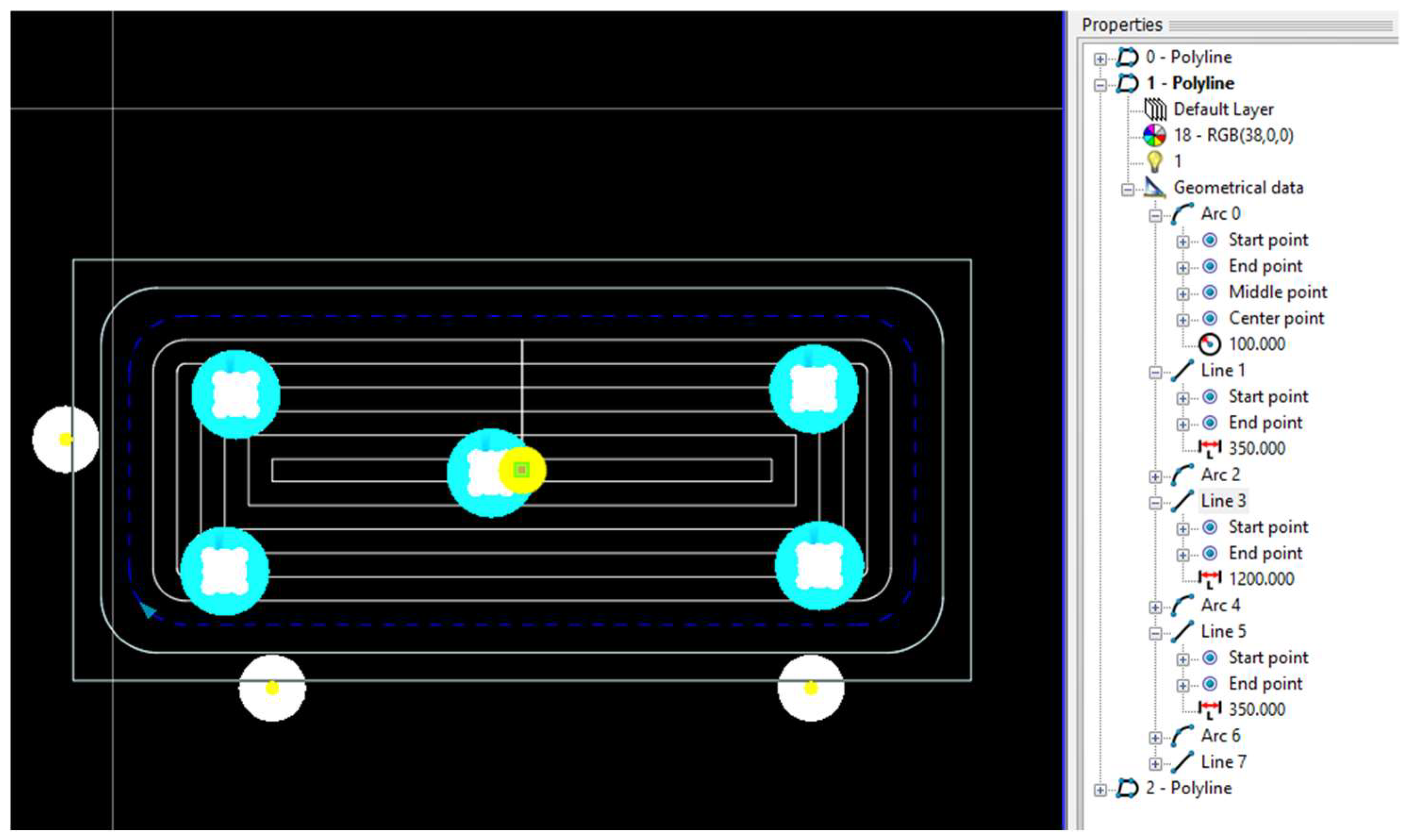
A tool path describes the specific route that a cutting tool takes during a machining process, such as milling or turning. Created by using ICAM3D software, it outlines the movement of the tool over the workpiece to achieve the desired shape. Proper management of toolpaths is crucial for achieving high-quality machining results, including precise dimensions and a smooth surface finish.
In addition, toolpaths consider factors like the properties of the cutting tool, machining parameters, and constraints related to the process, such as limitations of the tool holder, ensuring efficient material removal.
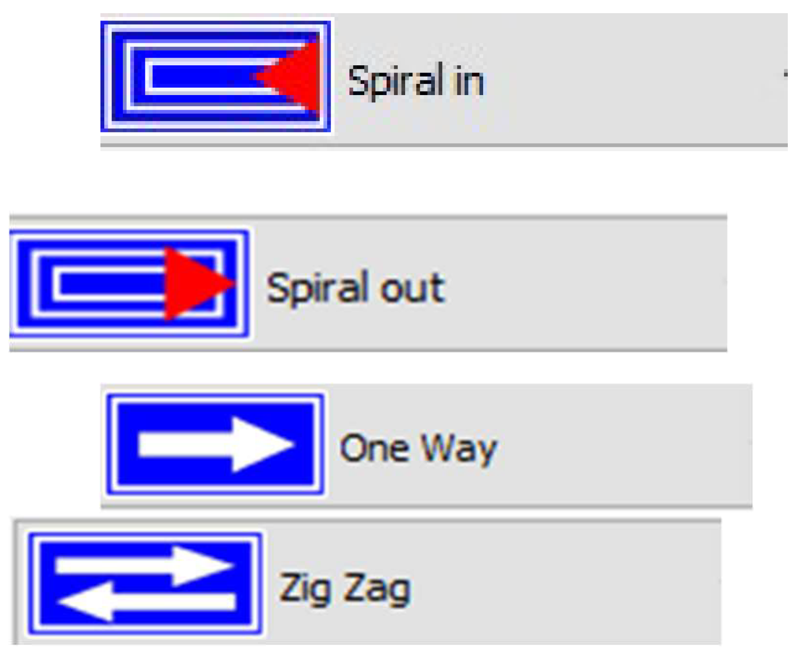
There are four variations of toolpath strategies in ICAM3D software: Spiral in, Spiral out, One Way, and Zig Zag. These strategies are labelled TP1 to TP4. The toolpath strategy parameter has been used in pocketing operations.
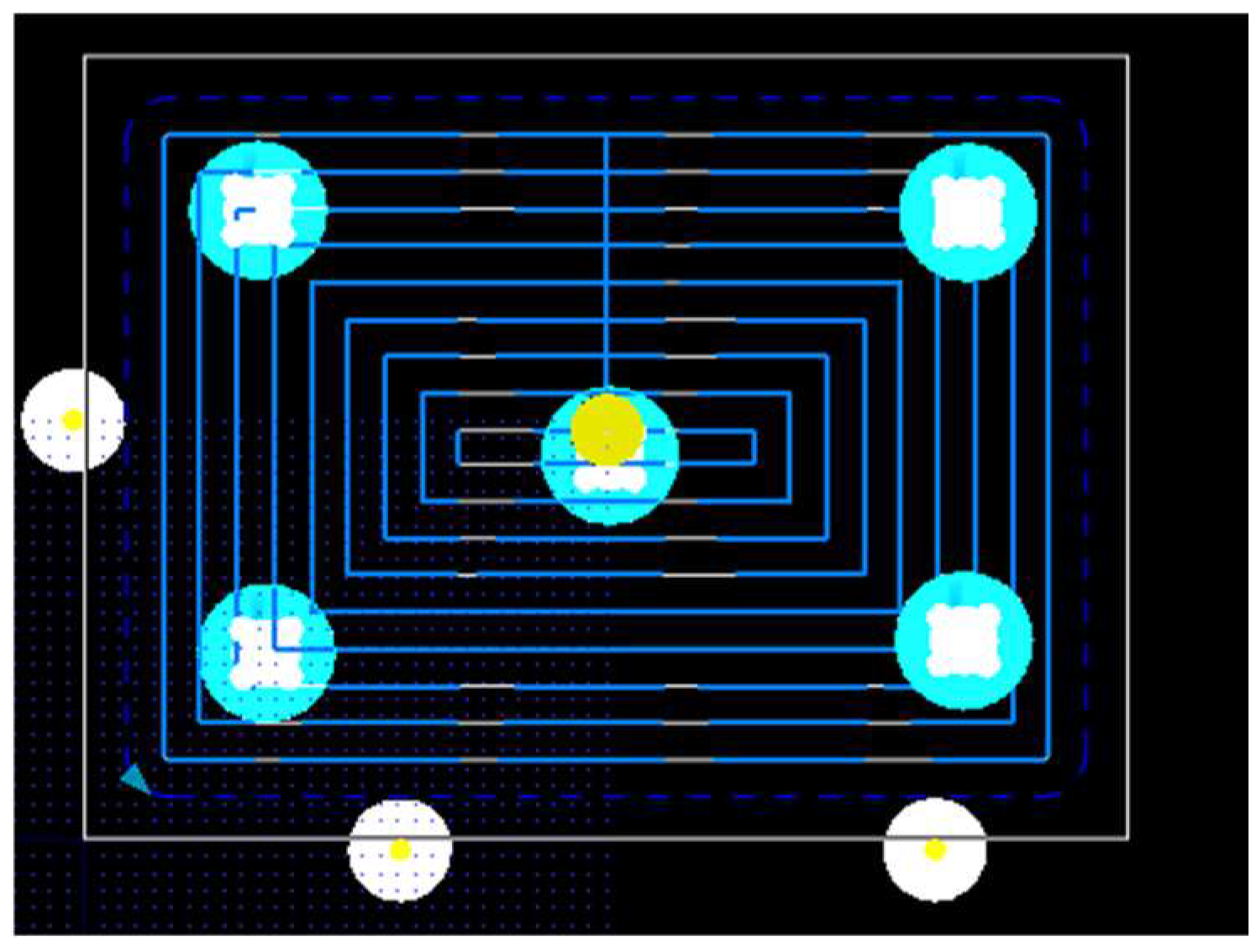
The
Figure 3 shows the toolpath strategies used in the projects. As seen in the
Figure 3, four toolpath strategies have been applied: Spiral In, Spiral Out, Zig Zag, and One Way. Based on these strategies, we will analyse which one is the most efficient for completing the work in the shortest time possible.
4. Results
Three projects have been considered in the analysis (P1 to P3). A variety of toolpath strategies (TP1 to TP4) in sequence are Spiral in, Spiral out, One Way and Zig Zag have been used including cutting speed, feed rate, and cut width have been considered.
4.1. Machining time of Workpiece P1
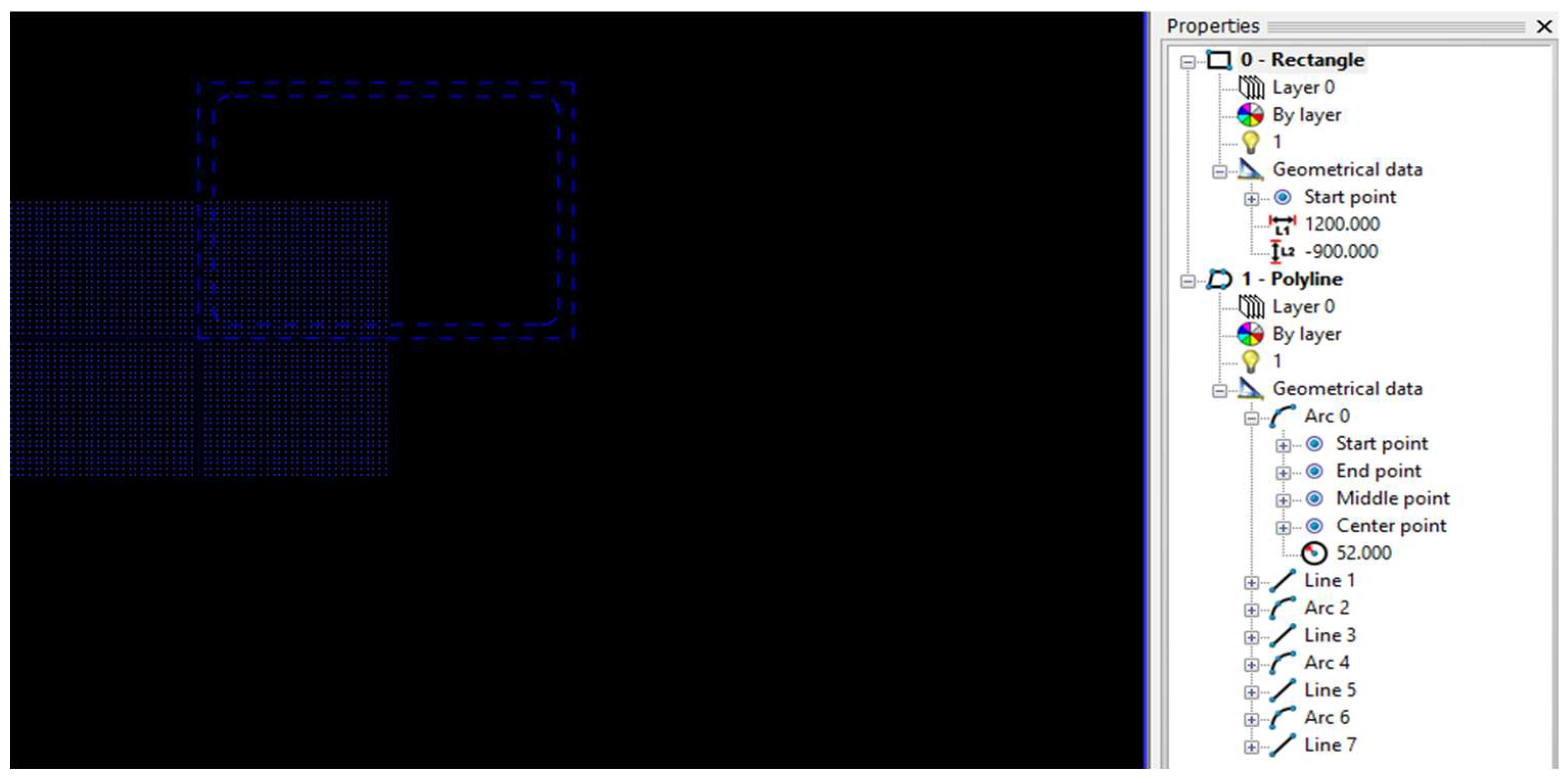
In the first project, a geometry with dimensions of 1200x900 has been used. The pocketing of the geometry has been performed with the T0050 tool. For the analysis, the total pocketing completion time has been recorded for the required dimensions, using four different tool path models.
Figure 4 shows the geometry used for the study. On the right side, the dimensions of the geometry have been displayed, including the 1200x900 dimensions and the arc of the geometry. The geometry has been created using ICAM3D software.
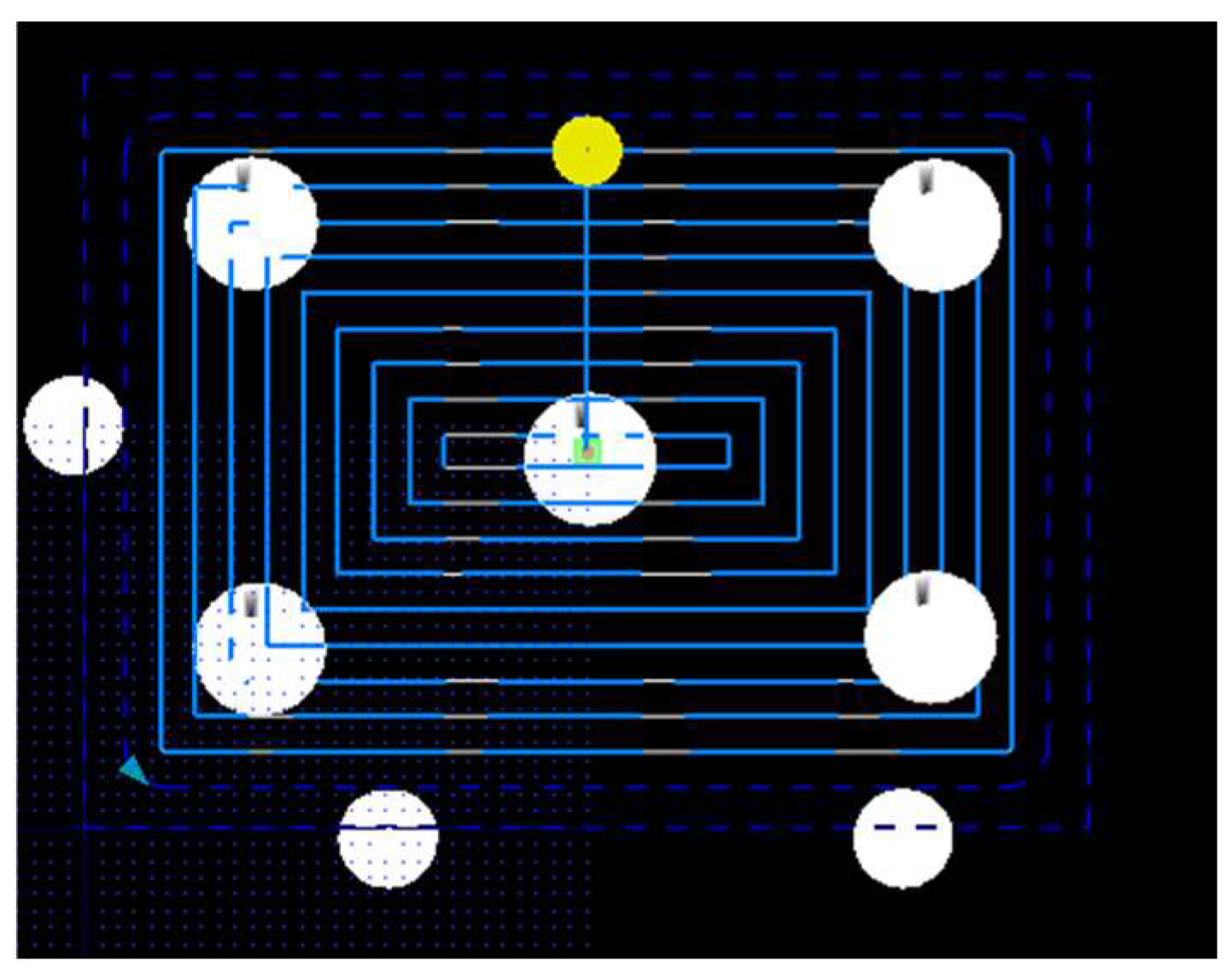
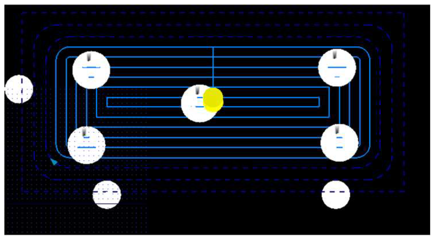
In the following pictures, one can see the types of toolpaths that have been used.
Figure 5,
Figure 6,
Figure 7 and
Figure 8 show the toolpath views after the completion of the P1 project. The project is first simulated in ICAM3D software and then processed on the CNC machine. The simulation helps determine whether the geometry and tool choice are suitable and can be completed successfully.
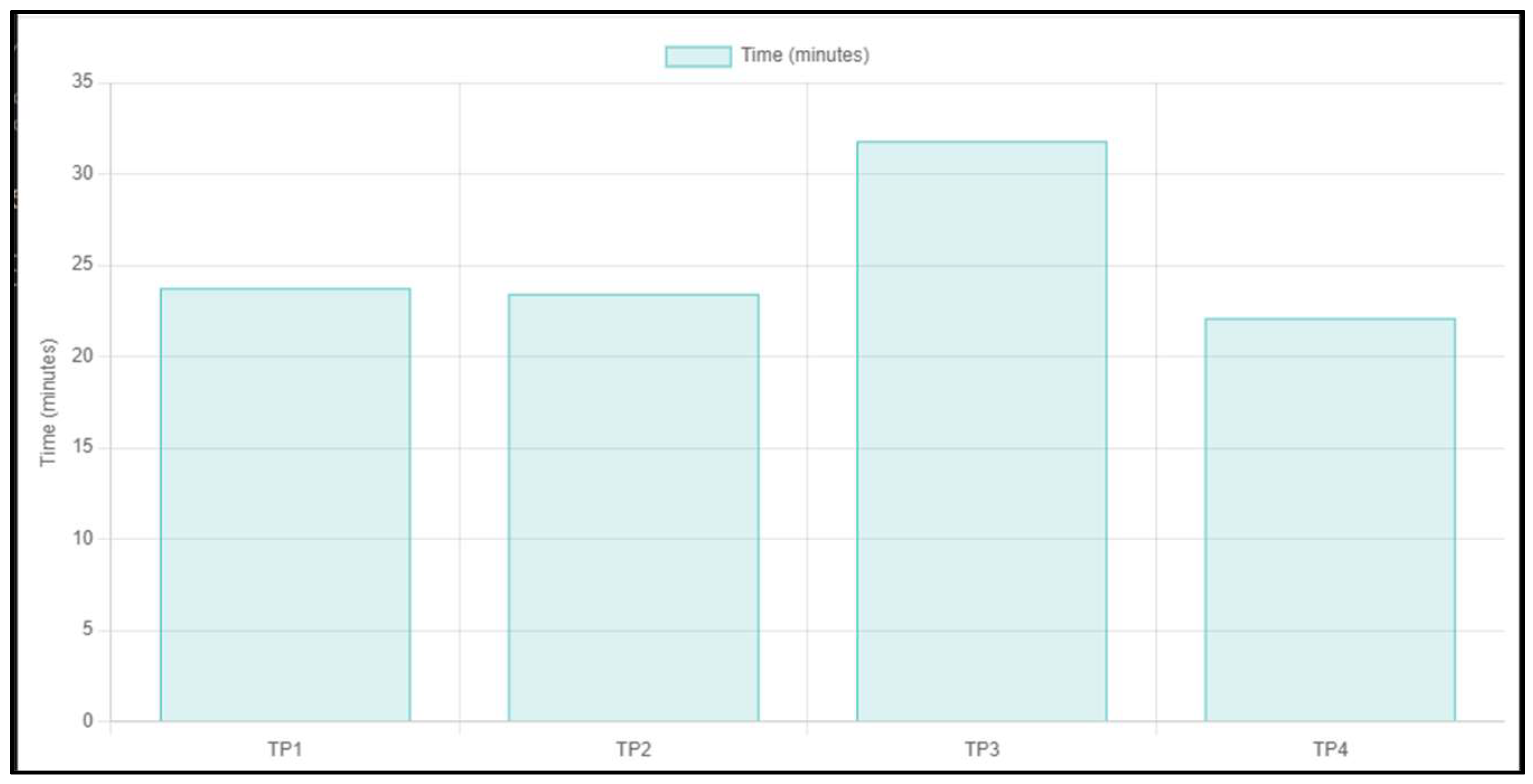
Table 2 shows the time taken for the project implementation using four strategies. The toolpath types are labelled TP1 to TP4. The results presented in the table have been given in minutes for each strategy. Here, the minimum machining time has been achieved with TP4 (Zig Zag) and is 26:37 minutes.
4.2. Machining time of Workpiece P2
In the second project (P2), the 160x750 geometry has been used. The pocketing procedure is the same as in the first case and has been carried out with the same T0050 tool. Pocketing has been performed using four variants of toolpaths, and the results have been presented on the side of the table.
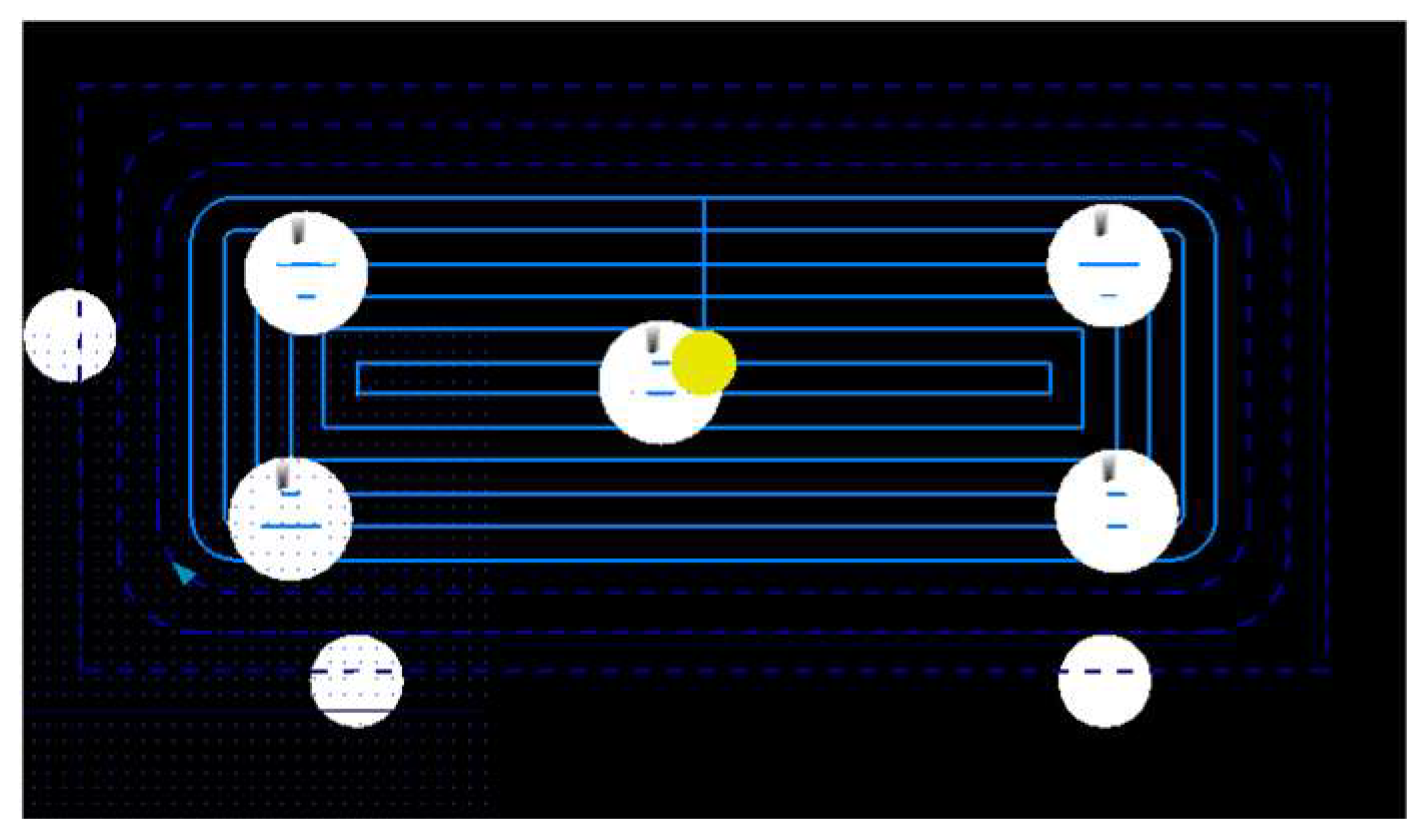
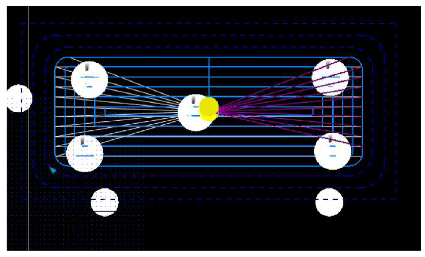
In
Figure 9, the second project, which we used as a case study for welding toolpaths has been presented. The geometry has been analysed using ICAM 3D software, and its dimensions were 1600x750. The geometry data has been displayed on the right side of the figure. After the geometry procedure, pocketing will be performed using the toolpath strategies from TP1 to TP4.
In
Table 3, the results obtained from the toolpath strategies TP1 to TP4 for the second project, along with the corresponding time results in minutes have been presented. Here, the minimum machining time has been achieved with TP4 (Zig Zag) and is 22:06 minutes.
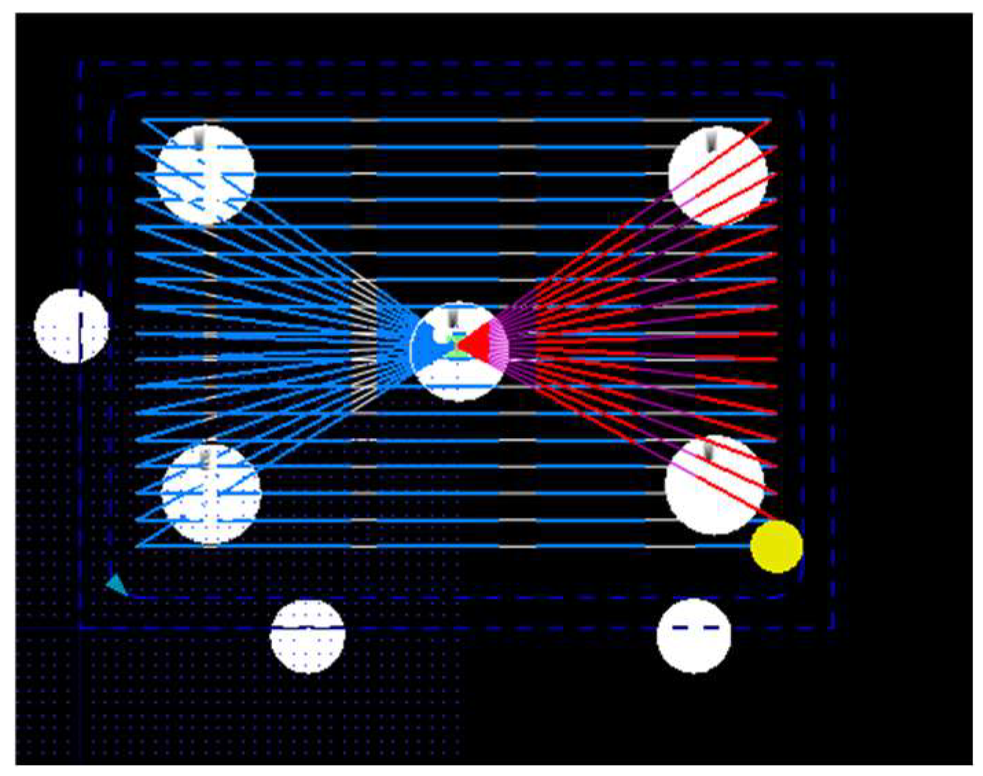
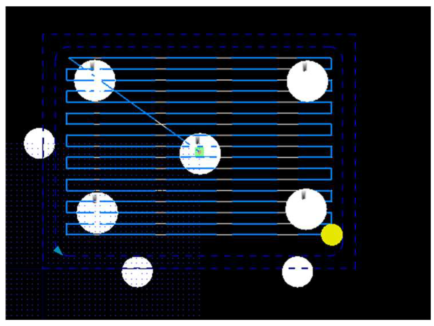
The following figures show the types of toolpaths used for the analysis.
In
Figure 10,
Figure 11,
Figure 12 and
Figure 13, the simulations for the second project (P2) have been presented. The simulation process, along with the CNC operations and toolpaths of the project, has been analysed in four ways, as described previously.
From the simulation, the direction of the CNC movement during each strategy of the studied toolpaths can be observed.
4.3. Machining time of Workpiece P3
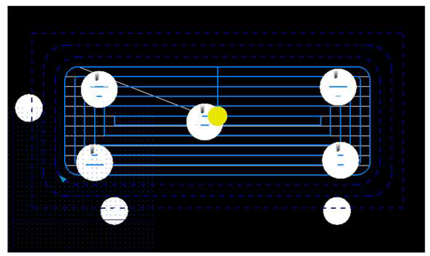
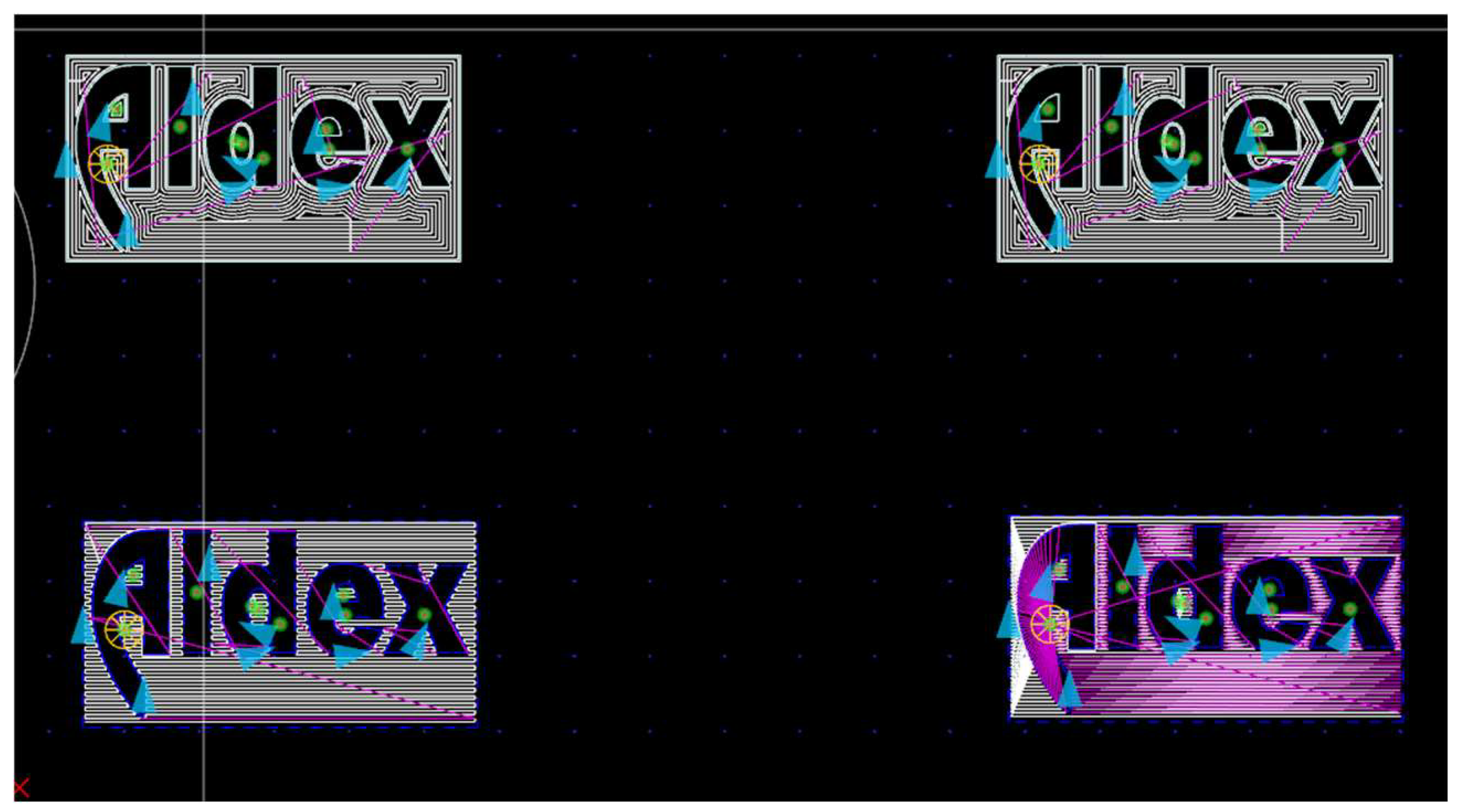
In the third project, a 100x50 logo has been used as the basis for the toolpath design. To achieve the pocketing of the geometry, the tool with the code T503 has been used. The time taken for pocketing with each tool path model is shown on the side of the table.
Figure 14 shows the logo used for the analysis in the third project, identified as P3. The P3 project has been completed using four toolpath strategies, and the results in terms of time have been presented in a table. From the image, one can see the paths of the toolpaths.
Figure 14 illustrates all four strategies in one image. The trench pocketing procedure has been performed with the T503 tool.
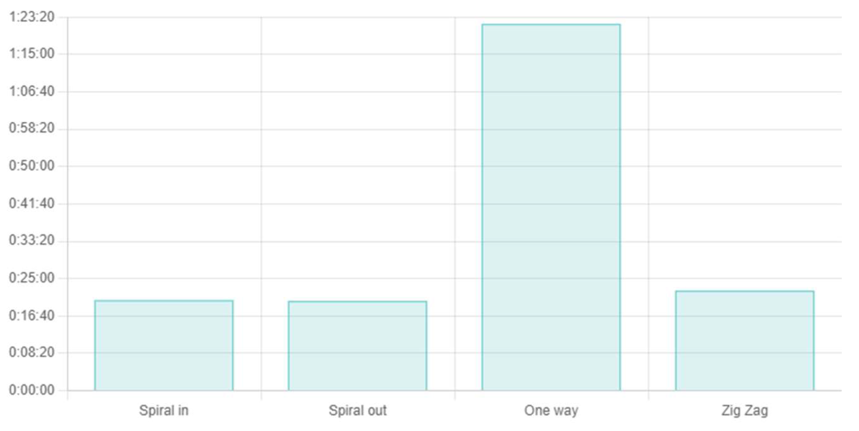
The
Table 4 shows the time taken to complete the trench project using the T503 tool. Here, the minimum machining time has been achieved with TP2 (Spiral out) and is 20:02 minutes.
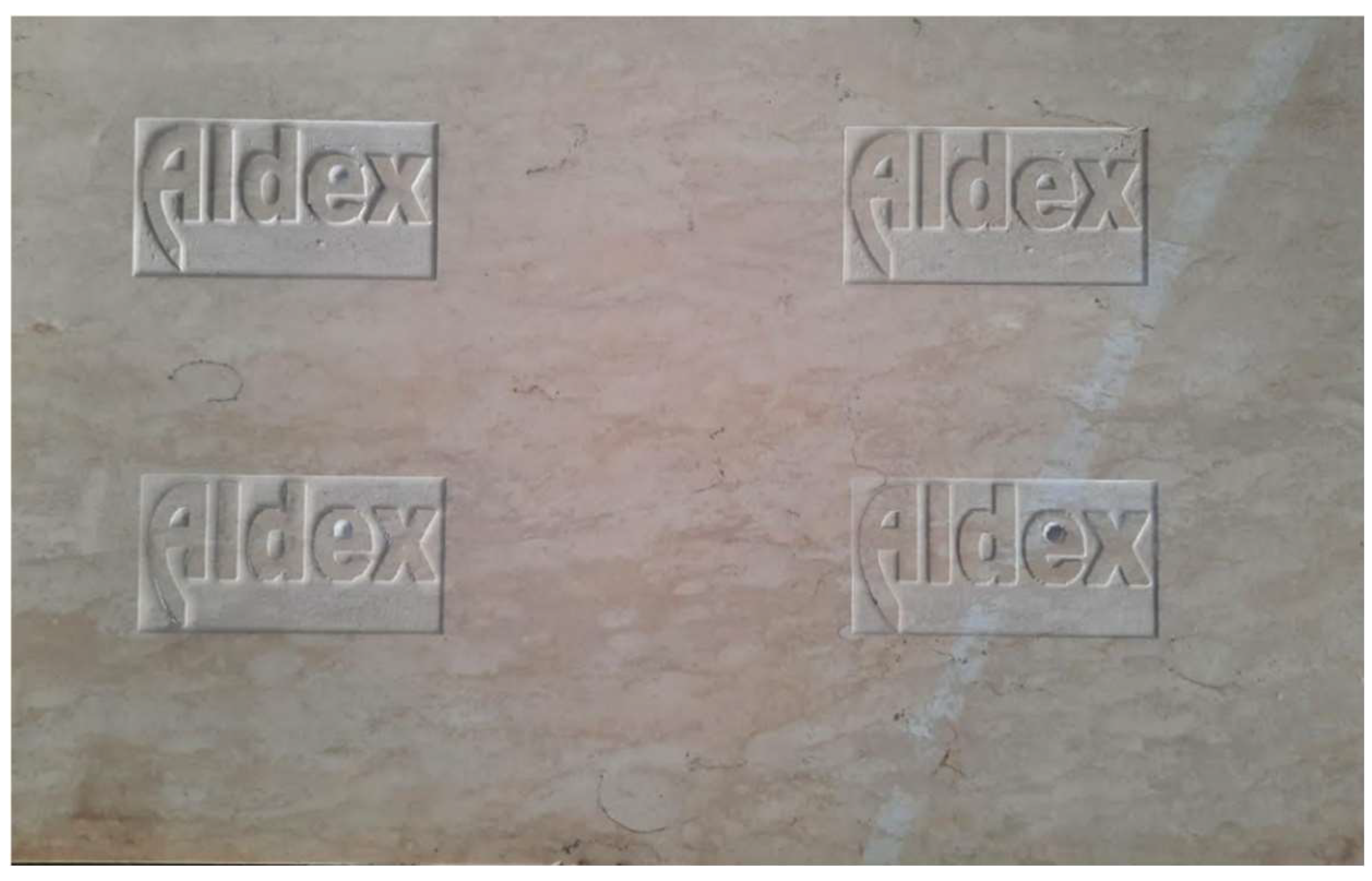
In the picture below, the final product made using four toolpaths has been presented.
In
Figure 15, the final product of the trench made in marble using the T503 tool has been presented. The work has been carried out using four toolpath strategies. The time results have been presented in tabular form, and the entire study has been analysed through graphs generated by JavaScript.
Table 5 shows the results obtained from the ICAM3D software and its simulation. The software provided good times for each project (P1, P2, P3). The table presents the best times for completing the projects, as well as the most favourable strategy for each, from TP1 to TP4. According to the ICAM3D simulations, the best strategy for the first two projects (P1 and P2) is TP4, which corresponds to the Zig Zag strategy. For the third project (P3), the most favourable strategy is TP2, corresponding to the Spiral Out strategy.
5. Discussion
Data analysis has been performed using JavaScript. The data have been collected from both simulation results of the CNC program and real-time CNC operations. Based on this data collection and analysis, the conclusions regarding the impact of toolpaths on machining time have been drawn. To create a graph with these values using JavaScript, one can use the Chart.js library, which is a popular and easy-to-use charting library. Below is given a simple example that shows how to create a bar chart with given data.
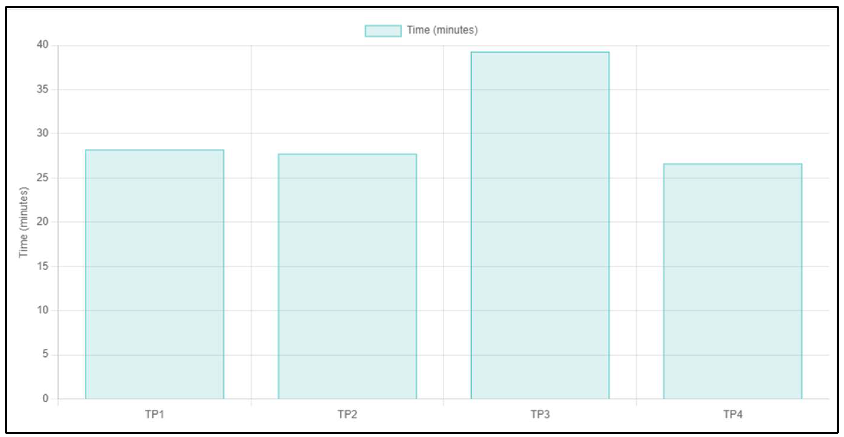
The
Figure 16 shows the results from JavaScript, it is known that the shortest time is from the path of the TP4 tool, i.e., the Zig Zag method.
In the figures below, the data for the initial project, P1 has been analysed.
From the graph generated using JavaScript, the best time has been achieved with the TP4 toolpath strategy, namely Zig Zag.
In the following figure, the graph displaying the data analysed using JavaScript has been presented. The data pertains to the second project, P2.
From the
Figure 17, it is evident that the toolpath is most optimized in the fourth mode, TP4, which corresponds to the Zig Zag type. The JavaScript code, highlighted and analysed in Visual Studio, has been used to generate the graphical results.
In the
Figure 18, the data for the initial project, P3 has been analysed.
From the above figures, it is evident that the toolpath is most optimized in the fourth mode, i.e., TP2, which corresponds to the Spiral out type.
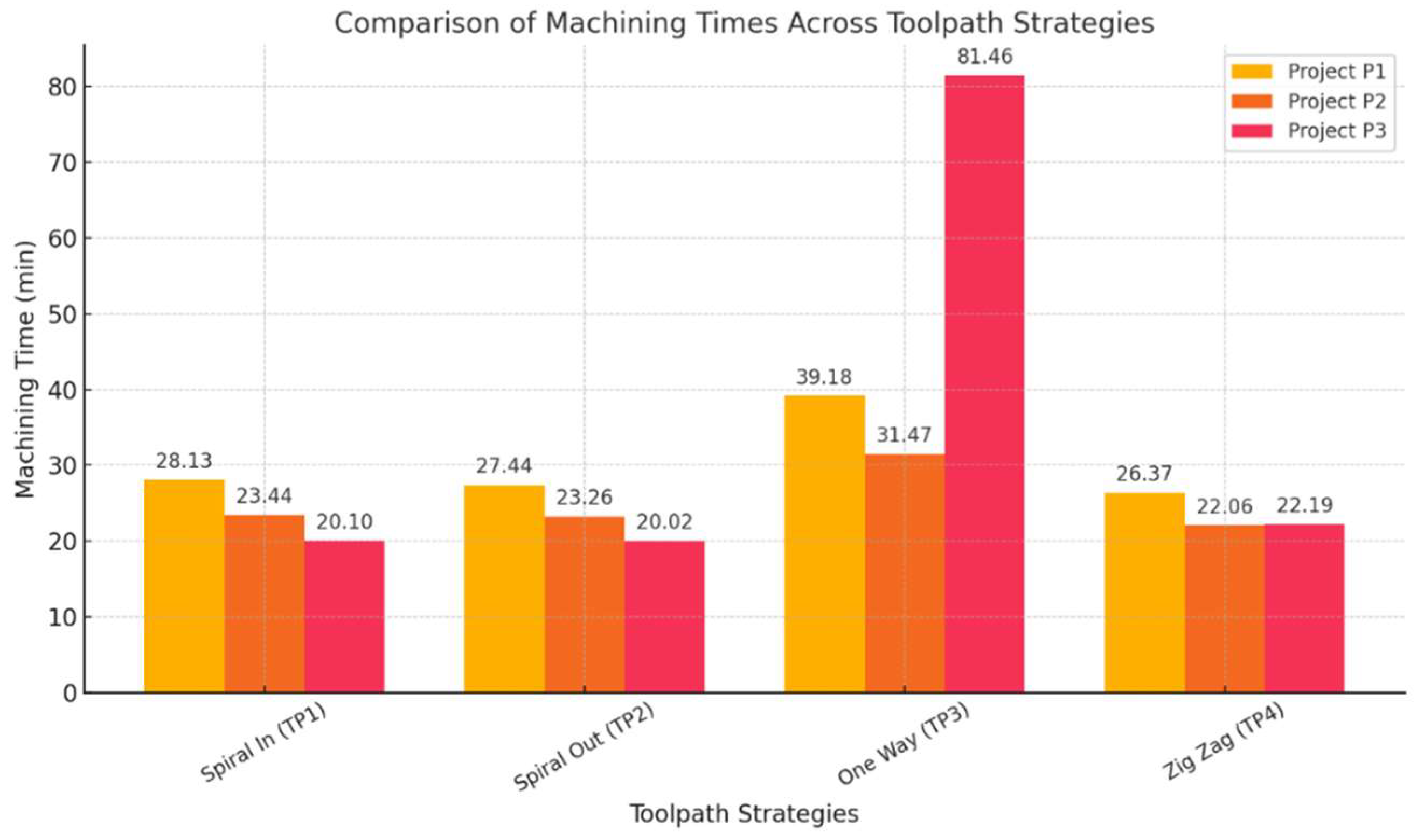
For the first project (P1), the minimum machining time has been achieved with TP4 (Zig Zag), taking 26:37, while the maximum time occurred with TP3 (One Way), taking 39:18.
For the second project (P2), the minimum machining time has been achieved with TP4 (Zig Zag), taking 22:06, while the maximum time occurred with TP3 (One Way), taking 31:47.
For the third project (P3), the minimum machining time has been achieved with TP2 (Spiral Out), taking 20:02, while the maximum time occurred with TP3 (One Way), taking 01:21:46.
Comparison of Machining process for all toolpath strategies has been shown in
Figure 19.
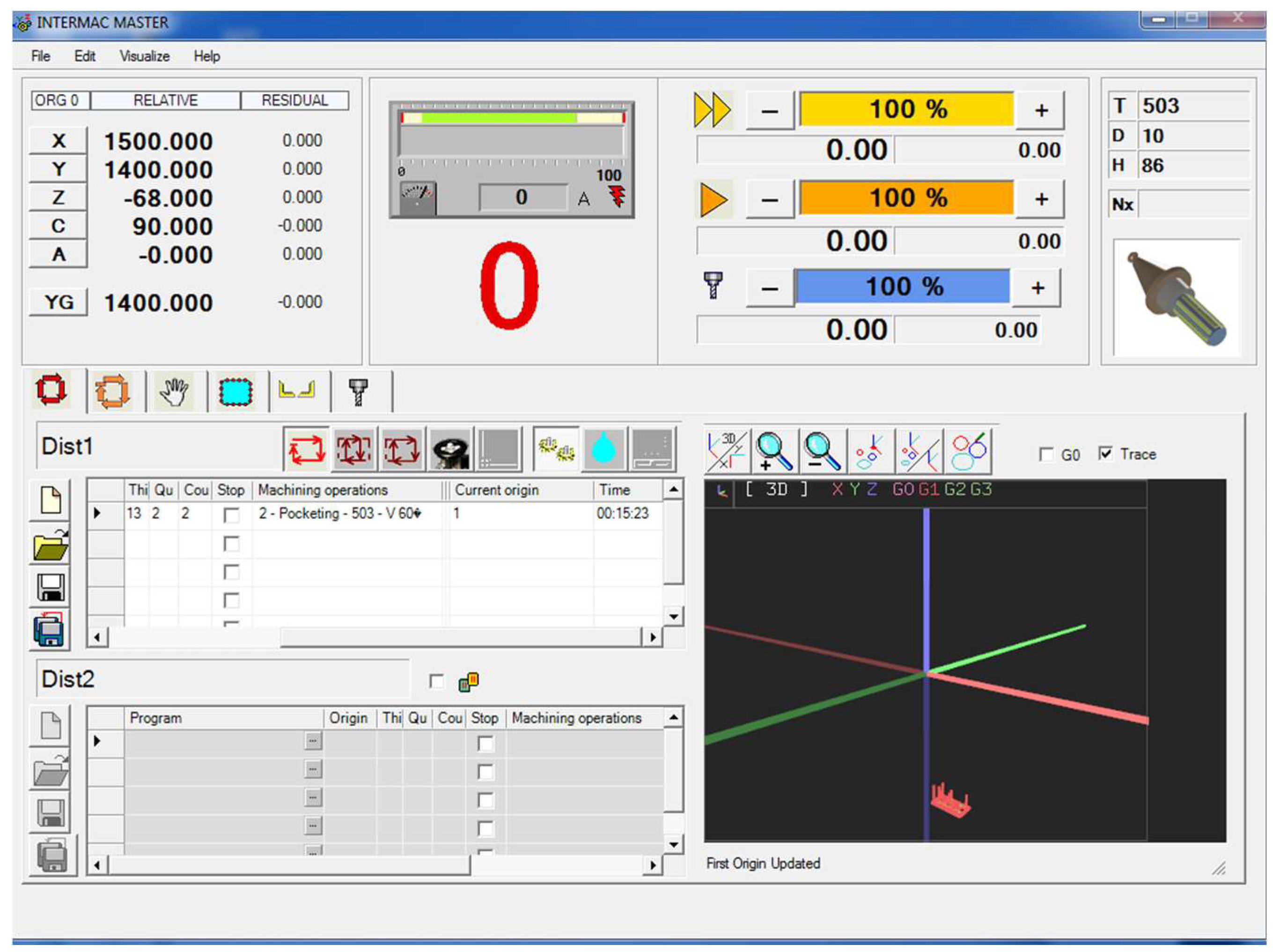
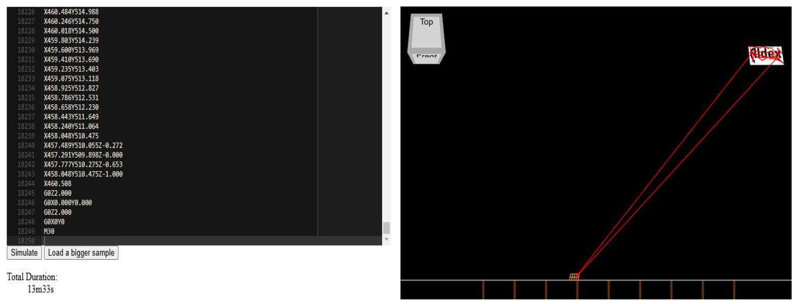
5.1. Additional optimization of the P3 project time
After receiving data from ICAM and the real data from the CNC for the P3 project, the final time for completing the project has been reduced to 15 minutes and 23 seconds,
Figure 20. To further optimize this work time, additional software, including ARTCAM and ASPIRE, to implement a new toolpath strategy has been used.
These software tools enabled to generate optimized G-code, which then has been tested using G-code simulators. As a result, improved outcomes that significantly reduced the CNC machine's working time for the project have been achieved. The optimization not only enhanced efficiency but also contributed to maximizing the overall performance of the CNC operation. The time optimized by the software and G-code was 13 minutes and 33 seconds. In
Figure 21, the simulation of time optimization through G-code has been presented.
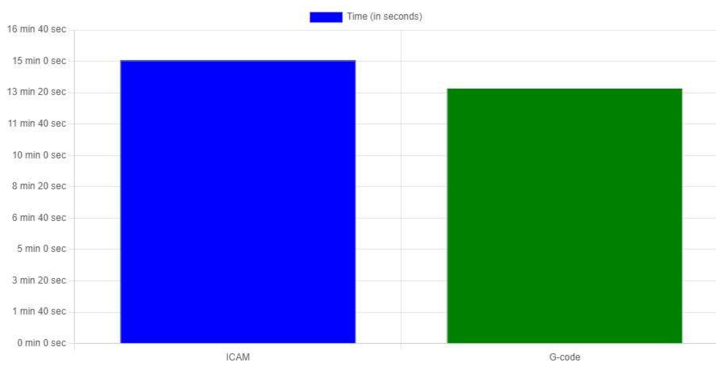
In
Figure 22 the completion time of the project using ICAM and G-code has been compared.
As is shown, the initial time to complete the project on the CNC was 15 minutes and 23 seconds. While after using G-code and other software, the machining time has been reduced to 13 minutes and 33 seconds.
6. Conclusions
In the study there were evaluated 4 toolpath strategies such as Spiral In, Spiral Out, Zig Zag, and One Way.
From the data analysis, one can conclude that the choice of toolpaths is very important in the operation of CNC machines. The wrong choice of tools will affect the machine's operating time, as seen in the P3 project, where the minimum work time is 00:20:02 and the maximum is 01:21:46.
However, the choice of toolpaths also depends on the geometry of the workpiece. From the analysis, one can found that the minimum machining time for the projects, and the corresponding toolpath types are as follows:
Overall, the minimum machining time has been obtained using TP4, the Zig Zag pattern, while the maximum time has been recorded with TP3, the One-Way pattern. The completion time for project P3 was 20:02 minutes. Given data from ICAM and the real data from the CNC for the P3 project, have reduced the final time for completing to 15 minutes and 23 seconds. The time optimized by the software and G-code further has been reduced to 13 minutes and 33 seconds.
Adopting a toolpath strategy in CNC machining is a powerful way to enhance productivity, quality, and cost-effectiveness in manufacturing. By focusing on optimized toolpath planning, manufacturers can achieve better precision, reduce cycle times, extend tool life, and improve overall operational efficiency. As industries continue to demand higher levels of precision and speed, strategies like toolpaths will remain key to staying competitive in the ever-evolving world of CNC machining.
The study helps engineers optimize workflows, especially for complex geometries. By identifying optimal strategies, it aligns sustainable manufacturing practices by maximizing resource utilization.
The future study should be focused on usage of Machine Learning models to predict optimal toolpath strategies based on workpiece geometry, material, and machining parameters.
Author Contributions
A short paragraph specifying the individual contributions is provided as follows: Conceptualization, A.P. and O.T.; methodology, A.G.; software, O.T. and B.B.; validation, A.P., B.B. and O.T.; formal analysis, A.G.; investigation, A.P.; resources, B.B.; data curation, O.T.; writing—original draft preparation, A.P.; writing - review and editing, A.P.; visualization, A.G.; supervision, A.P.; project administration, A.G. All authors have read and agreed to the published version of the manuscript.
Funding
This research received no external funding.
Data Availability Statement
All data are contained within this paper and repository search results (github.com).
Conflicts of Interest
The authors declare no conflicts of interest.
References
- Gavril, M.; Andrei, M.; Lucian, T. 2016. Increase Productivity and Cost Optimization in CNC Manufacturing. IManEE pp.1-6.
- Daneshmand, S.; Abdol Hosseini, M.M.; Aghanajafi, C. Investigating the Optimal Tool Path Strategies Based on Machine time in CAD-CAM. Aust. J. Basic Appl. Sci. 2011, 5, 2320–2326. [Google Scholar]
- Gologlu, C.; Sakarya, N. 2008. The effects of cutter path strategies on surface roughness of pocket milling of 1.2738 steel based on Taguchi method.
- Li, W.; Zein, A.; Kara, S.; Herrmann, C. An Investigation into Fixed Energy Consumption of Machine Tools. In Glocalized Solution for Sustainability in Manufacturing: Proceedings of the 18th CIRP International Conference on Life Cycle Engineering. 268-275. (2011).
- Johnson, H. Toolpath Generation and Optimization in CNC Machining. International Journal of Precision Engineering 2022, 29, 113–121. [Google Scholar]
- Smith, L.; Anderson, P. The Role of Toolpath Strategies in Modern CNC Machining. Manufacturing Technology Review 2021, 17, 58–65. [Google Scholar]
- Greenwood, R. Optimizing CNC Toolpaths for Precision and Efficiency. Journal of Advanced Manufacturing 2023, 41, 85–92. [Google Scholar]
- Taylor, M.; Lewis, A. Adaptive Toolpath Strategies for CNC Systems: A New Era in Manufacturing. Journal of Automation and Robotics 2021, 37, 101–108. [Google Scholar]
- M. Mattson, CNC programming: principles and applications. Cengage Learning, 2009.
- De Lacalle, L.N.L.; Lamikiz, A.; Sanchez, J.A.; Salgado, M.A. Toolpath selection based on the minimum deflection cutting forces in the programming of complex surfaces milling. Int. J. Mach. Tools Manuf. 2005, 47, 388–400. [Google Scholar] [CrossRef]
- Al-Kindi, G.; Zughaer, H. An Approach to Improved CNC Machining Using Vision-Based System. Mater. Manuf. Process. 2012, 27, 765–774. [Google Scholar] [CrossRef]
- Smith, L. Precision Machining with Advanced Toolpath Strategies. International Journal of Precision Engineering 2023, 29, 31–38. [Google Scholar]
- Jones, D.; Taylor, R. Optimizing CNC Machining: Cycle Time Reduction Strategies. Journal of Industrial Engineering 2021, 48, 78–85. [Google Scholar]
- Johnson, H. Maximizing Tool Life Through Optimized CNC Toolpaths. Advanced Manufacturing 2022, 33, 112–118. [Google Scholar]
- Williams, K.; et al. Achieving Superior Surface Finishes in CNC Machining with Optimized Toolpaths. Surface Quality Journal 2020, 17, 46–53. [Google Scholar]
- Anderson, P. Material Efficiency in CNC Machining: Optimizing Cost and Sustainability. Journal of Manufacturing Processes 2022, 45, 124–130. [Google Scholar]
- Greenwood, R.; Ford, T. Toolpath Simulation and Its Role in CNC Machining Safety. CNC Technology Review 2023, 12, 59–64. [Google Scholar]
- Miller, J.; Lewis, A. Material-Specific Toolpath Adjustments in CNC Machining. Materials Engineering 2021, 58, 87–94. [Google Scholar]
- Amjad Barzan Abdulghafour, Ahmed Thamer Hassan. (2020). Automatic Tool Path Generation Based Freeform Features Recognition. 13th International Conference on Developments in eSystems Engineering (DeSE).
- Liao, J.; Huang, Z. Data model-based toolpath generation techniques for CNC milling machines. Front. Mech. Eng. 2024, 10, 1358061. [Google Scholar] [CrossRef]
- Venturini, G.; Grossi, N.; Morelli, L.; Scippa, A. A Non-Uniform Offset Algorithm for Milling Toolpath Generation Based on Boolean Operations. Appl. Sci. 2022, 13, 208. [Google Scholar] [CrossRef]
|
Disclaimer/Publisher’s Note: The statements, opinions and data contained in all publications are solely those of the individual author(s) and contributor(s) and not of MDPI and/or the editor(s). MDPI and/or the editor(s) disclaim responsibility for any injury to people or property resulting from any ideas, methods, instructions or products referred to in the content. |
© 2024 by the authors. Licensee MDPI, Basel, Switzerland. This article is an open access article distributed under the terms and conditions of the Creative Commons Attribution (CC BY) license (http://creativecommons.org/licenses/by/4.0/).