
Submitted:
25 December 2024
Posted:
26 December 2024
You are already at the latest version
Abstract
This paper investigates the trajectory tracking control problem of unmanned surface vessel (USV) with time-varying communication delays by taking advantage of the discrete-time sliding mode control approach and networked predictive control strategy. To address the aforementioned problem, a novel networked predictive control scheme based on a discrete-time sliding mode is proposed. Forward Euler discretization technology is applied to construct the discrete-time model of the USV. Then, a virtual velocity controller is developed to convert the trajectory tracking into virtual velocity tracking which can be achieved by utilizing a sliding mode control. Subsequently, a networked predictive control technique is performed to make the compensation for time-varying delays. Finally, theoretical analysis and extensive comparative simulation tests demonstrate that the proposed control scheme guarantees complete compensation for time-varying delays while ensuring the stability of the closed-loop system.
Keywords:
unmanned surface vehicles
; trajectory tracking
; discrete-time sliding mode control
; time-varying delays
; networked predictive control
1. Introduction
In recent years, unmanned surface vehicles (USVs), as marine unmanned equipment, have received widespread attention and applications in military and civilian fields, such as marine resource exploration [1], maritime attack and defense [2], water quality monitoring [3], maritime rescue [4], and maritime mapping [5]. On the one hand, with the rapid development of wireless sensor network technology [6], microelectronics technology [7], internet of things technology [8] and advanced control theory [9], the functions of the USVs are greatly expanded and the level of automation is increasing day by day. On the other hand, the adoption of the aforementioned technologies in the USV industry, in particular the introduction of communication networks, brings new challenges to the design of the USV control system. Since the communication network serves as a bridge to integrate various control devices into a whole, control signals and feedback signals are transmitted via the network, so the USV control system represents a standard cyber-physical system (CPS). It is well known that time delay exists widely in CPS, which not only increases the difficulty of control design but also degrades the control performance of the system and even causes the control system to lose stability [10]. Therefore, for a special CPS such as the USV, the trajectory tracking control issue associated with time-varying communication delays is worthwhile to pay attention to.
Trajectory tracking control plays an important role in the engineering application of the USV, which ensures that the USV sails along the desired trajectory in order to fulfill given tasks. Numerous control technologies have been introduced into USV trajectory tracking control, and fruitful results have been reported. Sliding mode variable structure control ( i.e., sliding mode control, SMC) [11,12,13,14,15] is a frequently used strategy because it is insensitive to unknown disturbances and parameter disturbances and is very effective for USVs with nonlinear dynamic characteristics. However, the SMC can effectively handle trajectory tracking to a certain extent, its inherent switching characteristic will cause system chattering, which will further lead to excessive wear and shorten the life of the actuator. To overcome the negative effects of the SMC mentioned above, some improved schemes on the basis of SMC are proposed. For instance, the Super-Twisting SMC is proposed by Liu to solve the trajectory tracking control of USV in literature [16], with the help of Super-Twisting technology, the chattering effect caused by SMC is reduced. The more studies of the Super-Twisting SMC for the USV tracking control can be found in [17,18,19]. Another well-liked alternative is the adaptive control scheme [20,21], which is introduced into SMC and has good a ability to suppress chattering. In [20], the authors design an adaptive sliding mode controller to achieve surge velocity and heading tracking, and thus finally achieve accurate trajectory tracking of the USV by combining a LOS guidance algorithm. From the above discussion, it is shown that the adaptive control approach introduced into the sliding mode controller simultaneously mitigates chattering and is robust to bounded uncertainties/disturbances. Additionally, the trajectory tracking control of the USV can also be realized through the other control strategies such as model-free control [22], robust control [23], fuzzy control [24], reinforcement learning control [25], model predictive control [26] and backstepping control [27]. It should be noted that the controller of the USV is usually digital, thus, a discrete-time controller is more attractive. Studies related to the application of discrete-time control design are given in the literature [28,29,30]. Although the aforementioned control methods can effectively address the USV trajectory tracking control problem, the time-varying delay has yet to be taken into account, and there is rare study in this field.
In order to overcome the negative effects of time-varying delays, two major types of control strategies have been proposed, namely the passive compensation strategies and the active compensation strategies. The core idea of passive compensation is to use Lyapunov stability theory to construct the Lyapunov function of the control system [31,32]. since this approach focuses more on the stability of the control system, it inevitably makes a compromise between control performance and stability [33]. From the above perspective, the control design of the system is naturally conservative, which means that control performance will be sacrificed to satisfy the stability of the system. For the active compensation strategy, the main study of that is predictive control technology. Predictive control technology is based on a model prediction scheme, which is an optimal control strategy determined by using current and past information of the controlled object to predict system performance in the future [34,35]. In other words, model predictive control technology possesses the inherent advantage of overcoming time delays. Thus, the active compensation strategy based on predictive control technology is particularly suitable for time-delay systems. In addition, for the purpose of actively compensating for the network delay of CPS, the network predictive control has been presented in literature [36,37]. At the same time, the analysis shows that the control performance of the delay system using networked predictive control is similar to that of the system without delay. It is worth noting that the research object of the active compensation strategy mentioned above is the fully actuated system, which cannot directly cope with the delay control problem of the underactuated USV in the network environment. Hence, the networked predictive control scheme needs to be redesigned to make it suitable for trajectory tracking control of underactuated USV with time-varying delays.
At the present, networked predictive control technology is widely employed in trajectory tracking control under communication constraints due to its ability to actively compensate for system delays. Aiming at trajectory tracking control of unmanned vehicles in a network environment, in [38], Zhang designs a tracking controller based on networked predictive control technology to achieve accurate trajectory tracking under time-varying communication delays. In this study, only fixed delays are considered, and time-varying delays are not considered. Chen et al. introduce networked predictive control into collaborative path tracking of unmanned vehicles [39], and the time-varying delay of the system is accurately compensated with the help of the designed two data buffers and networked predictive control strategy. However, the control objects involved in the above studies are all fully actuated systems. To the best of our knowledge, for typical nonlinear underactuated systems such as USVs, there is no research on using networked predictive control strategy to solve the trajectory tracking control problem of USVs under time-varying delays. Motivated by the proposal in [37] to design a networked predictive control architecture to compensate for the time delay actively, this work designs a networked predictive control scheme based on discrete-time SMC to suppress the negative impact of time-varying delays on the USV control system.
Inspired by the above discussion, this paper focuses on developing a solution based on networked predictive control to deal with the trajectory tracking control of the USV suffering from time-varying network delays. With the application of dual-loop technology, the controller design is divided into inner-loop controller design and outer-loop controller design. In specific, the outer-loop controller is composed of a discrete-time surge virtual velocity control law and a discrete-time sway virtual velocity control law. In line with that, the inner-loop controller consists of a surge thrust controller and a steering torque controller, both of which are discrete-time sliding mode controllers. Furthermore, a networked predictive control strategy is implemented based on the above-mentioned dual-loop controller to achieve accurate compensation for time-varying network delays, thereby ultimately realizing accurate tracking for the USV’s desired trajectory.
The main contributions of this paper are summarized as follows:
- An improved discrete-time virtual speed control law is proposed. Compared with the one proposed in literature [30], the improved discrete-time virtual velocity control law is more simpler and requires less calculation. The purpose of introducing the discrete-time virtual velocity control law is to transform the trajectory tracking problem into speed tracking.
- In the light of the USV’s discrete-time dynamic mathematical model and discrete-time sliding mode control theory, the surge thrust control law and steering torque control law are constructed to realize asymptotic tracking for the virtual velocities.
- Networked predictive control is introduced to nonlinear underactuated USV for the first time. Benefiting from networked predictive control, the time-varying delays existing in the communication network are completely compensated.
The remainder of this paper is structured as follows. The problem construction including USV modeling, the influence of the network environment on USV control and the control objectives are stated in Section 2. Section 3 gives the detailed design process of the networked predictive sliding mode control strategy and the stability proof of the developed controller. Numerical simulation and result analysis for USV trajectory tracking are described in Section 4. Finally, the conclusions of this study are drawn in Section 5.
2. Problem Formulation
2.1. Dynamic model of the USV
The kinematic and dynamic equations of the USV are characterized by two reference frames as shown in Figure 1. The earth-fixed reference frame is used to construct the kinematic equations of the USV and the dynamic equations of the USV are presented in the body-fixed reference frame . With the help of the above two reference frameworks, the mathematical model of USV is expressed as follows:
where the position and heading of the USV are expressed in the earth-fixed reference frame, i.e, . is the velocity vector, which is composed of the linear velocity vector and heading angular velocity r. is the control force and torque generated by the propulsion system of the USV. is the external disturbance vector of the USV caused by wind, wave and currents. is the transformation matrix between the earth-fixed reference frame and the body-fixed reference frame, which is expressed as follows
where denotes the inertia matrix of USV. is denoted as the Coriolis force centripetal matrix of the USV. is the hydrodynamic damping coefficient matrix. Specifically, , and are defined as
To facilitate the implementation of the digital controller, the forward Euler method is used to discretize the (1) and (2) continuous-time system equations by using the sampling period . The discrete-time system equations are given in the following.
Property 1.
is an orthogonal matrix and satisfies. For the matrix , each element on its diagonal satisfies .
2.2. Networked Control Architecture for the USV
A closed-loop control system that connects sensors, controllers, and actuators via digital networks is called as a networked control system. Figure 2 depicts the networked control structure of the USV. From Figure 2, it can be seen that the controller is deployed on a remote shore base or mother ship (control station). Communication networks exist between the sensor and the control station, as well as the actuator and the control station. Note that the USV control system will unavoidably encounter time-varying delays due to the existence of the networks. In order to better characterize the above time-varying delay, the communication link including the sensor, communication network and control station is called the feedback channel, and its time-varying delay is denoted as . In the same way, the communication link including the actuator, communication network and control station is called the forward channel and the time-varying delay of the channel is .
2.3. Control Objective
In this work, for the USV trajectory tracking control problem in a network environment, we are dedicated to develop a networked predictive sliding mode control technology to overcome the negative impact of the time-varying delays. Under the action of the designed control technology, the time-varying delays in the USV control system are completely compensated, and the trajectory tracking error of the USV converges to a region near zero. To achieve this goal, a dual-loop cascade control strategy combined with networked predictive control technology is developed to design the trajectory tracking controller of the USV. First, the virtual velocity control law of the outer-loop is designed in the light of the position error generated by the USV’s desired position and actual position. Then, trajectory tracking control is converted into virtual velocity tracking control by means of the outer-loop controller, and a discrete sliding mode control strategy is introduced into the inner-loop to realize virtual velocity tracking. Finally, networked predictive control technology is implemented in the above-mentioned dual-loop controller to compensate for the time-varying delays in the communication channel, so as to achieve trajectory tracking of the USV with communication constraints.
Assumption A1.
The USV’s desired trajectory is a smooth curve, and its first derivative exists and is bounded.
3. Networked Predictive Sliding Mode Controller Design
In this section, the main task is to design a networked predictive control strategy for the USV in a network environment. It is worth mentioning that the focus of this paper is the design of control strategies for the USV control system subjected to time-varying delays, so the control strategy design does not consider the external disturbance of the USV. This also means assuming that the external disturbances of the USV is known and can be fully compensated by the controller. Considering that the external disturbances can be quantitatively characterized by experiments and measurements, the above assumption is reasonable and feasible. As a result, the system disturbances () are not considered in the subsequent control strategy design. The detailed control scheme consists of three parts, i.e., the outer-loop discrete-time virtual velocity control law, the inner-loop sliding mode control strategy and the networked predictive control strategy. The controller design and its stability analysis are detailed in the following.
3.1. Networked Predictive Control Framework for the USV
The overall architecture of networked predictive control for the USV is illustrated in Figure 3. As can be seen from Figure 3, the networked predictive controller is comprised of three principal components, namely, the prediction controller, the communication compensator, and data buffers located on both sides of them. In accordance with the actual physical point of view, in order to prevent networked system from becoming open loop, it is reasonable to posit that only a finite number of consecutive data losses can be tolerated. In addition, the following assumptions are made.
Assumption A2.
1) The delay of the feedback channel from the sensor to the predictive controller is and its upper bound is (i.e, ); 2) The delay of the forward channel from the predictive controller to the actuator is , and its upper bound is (i.e, ); 3) The upper bound of consecutive data loss in both the feedback channel and the forward channel is . 4) Each data is timestamped as it is sent via the network.
Moreover, clock synchronization of all nodes is also an issue in networked control systems, there are several ways to achieve clock synchronization for digital devices. Since the networked predictive control problem of the USV is the main focus of this study, it is naturally assumed that the clocks of each component in the networked control system has been synchronized.
In order to handle time-varying delays and data loss, the following data sending mechanism is employed.
-
The velocity and position information of the USV is measured by the sensors and transmitted in the following data packets.Where and .
-
In the same way, to prevent data loss in the forward channel, the following control prediction sequence is transmitted from the predictive controller side to the communication compensator side at time k.are the control prediction sequence at the future instants, which are calculated by using the predictive control algorithm through the received motion information of the USV delayed by steps. Where .
In terms of the feedback signals and control prediction are sequences accompanied by timestamps, two data buffers need to be set up to reorder the received data on the basis of timestamps. One is that data buffer A is located on the predictive controller side, and the other is data buffer B located on the communication compensator side. Hence, under assumption 2, the output on the predictive controller side and the control input on the actuator side are always available for use.
The control prediction sequences required by the USV actuators are preserved in buffer B. In accordance with the timestamp technology and the measurement method round-trip delay, Communication delays can be identified. Then, the latest predictive control input from the control prediction sequence (8) is selected by the communication compensator at the time k. Assume that the time delays of the forward channel and feedback channel are and respectively. In this way, one can have:
3.2. Design of the networked predictive controller for the USV
The networked predictive controller of the USV is comprised of two parts, the prediction generator and the communication compensator. The specific design procedure of the above parts is detailed in the following.
3.2.1. Prediction generator
A. Design of the virtual velocity control law
From Figure (3), the actual velocity and position of the USV are received by the controller after a delay of steps at the time k. Therefore, the available feedback information on the controller side is and . On the basis of such feedback information, the control input is derived by using a discrete sliding mode scheme. The specific design procedure will be given later. Using , and , then perform the following multi-step output predictor based on the nominal model, one can yield the following:
where and respectively denote the predicted values for the velocity and position at time using the velocity and position of the USV up to time , and . is represented as . The mark ’^’ on a variable indicates that the variable is a predicted value.
Through the implementation of the above predictive procedure, the velocity and position information of the USV at time k is available on the controller side. In what follows, the virtual velocity control law is designed. The trajectory tracking errors of the USV are defined as:
Let’s define and in (12) as the virtual velocity control variable. For the purpose of realizing the trajectory error of the USV converging to zero, the virtual velocity control law is designed as:
where and are the virtual velocity control laws of the USV in the surge and sway directions respectively. Where , and are the positive constants to be designed. The function of the term in (13) is to prevent the virtual velocity control law from being too large. If it is too large, the virtual velocity will exceed the USV’s normal sailing speed, resulting in trajectory tracking failure. and are provided by the desired trajectory stored in the controller.
Theorem 1.
Proof
From the above equality, it is obvious that if and
satisfy then (14) is simplified as:
Where .
Let’s construct the following Lyapunov function
Hence, from (18) we can deduce that if and hold, the trajectory tracking error of the USV converges to zero asymptotically. □
B. Predictive discrete-time sliding mode controller design
On the basis of the state prediction and the surge virtual velocity control law, the tracking error of the surge virtual velocity is defined as:
According to (19), the discrete-time integral sliding mode surface is constructed
where , is the sampling time.
In the light of discrete-time sliding mode theory, under ideal sliding mode, one gets
Combining (19) and (22), and using the expansion of (10), the following equivalent control in the surge direction is obtained.
For the purpose of stabilizing the system on the sliding surface, the switching control law is selected, where is a constant. Therefore, at the controller side, the overall control law in the surge direction for the time k can be obtained by adding the equivalent control and the switching control law, and its specific expression is
Up to this point, the thrust control law in the surge direction is accomplished. Next, the details of the steering torque control law in the sway direction are given.
Considering the time delay and in the light of the state prediction, the tracking error of the sway virtual velocity is defined as:
The heading is controlled by the steering torque. For the sake of making the steering moment term appear in the sliding mode surface, the differential discrete-time sliding mode surface is constructed as follows:
where . In the light of , the following equality is obtained
Using the expansion of (10) and substituting it to (27), it can conclude that
where and are the predictions of the virtual swaying velocities at the time and , respectively, are jointly determined by the prediction of position and the desired position at the time and .
Let’s Denote as , thus, the term in (28) can be rewritten as follows
To facilitate simplicity, let the last four terms on the left in (28) be denoted , i.e.,
Let the term in "{ }" on the left side of the above equality be represented as , and the term on the right side be expressed as . Then, by using (31), the following equivalent steering torque control law can be given by
Similar to the thrust control law, is the switching control law, which is used to stabilize the sliding mode surface in the surge direction, where is the constant to be designed. In this way, by adding and , the final overall steering torque control law is derived as follows
Hence, the predictive discrete-time sliding mode controller at the time k is completed in the surge direction and heading direction. It can be seen from and that the delay of the feedback channel is compensated for. To compensate for the time-varying delay of the forward channel at the time k, steps control prediction is implemented according to (10), (11)-(13), (19)-(24), and (25)-(33), and thus the following predictive control sequence is obtained on the controller side.
where and .
3.2.2. Communication Compensator
In the actuator of the USV, the communication compensator is set. The predictive control sequence (34) on the controller side is packed with timestamps and transmitted to the buffer B on the communication compensator side. Then, the buffer is used to preserve the received control sequence and reorder them according to timestamp. Finally, the proper predictive control is selected in the light of the system delay and sent to the actuator of the USV. In specific, assume that the feedback channel and forward channel delays at time k are and , respectively. Thence, the network communication compensator selects the following control signal to the USV at time k.
3.3. Stability Analysis of the Controller
The closed-loop stability of the networked predictive controller is analyzed in this section. It should be pointed out that the analysis of the closed-loop system consists of two parts: one is the stability of discrete-time sliding mode control, and the other is the stability analysis of the closed-loop system after the implementation of the predictive control strategy.
First, the discrete-time sliding mode controller is analyzed.
Lemma 1.
(Ghabi et al., 2018) The necessary and sufficient conditions for the stability of the discrete sliding mode system are that the selected sliding mode surface satisfies the condition:
Considering (37), for the sliding surface , it is noticed that the holding of the Lemma 1 can be ensured by the following inequality.
As a result, the surge thrust controller is stable if the above inequality holds. Further, the stability analysis of the steering torque controller is presented. For the purpose of that, a similar practice is implemented. By substitution of (26) and (33) into (10), one obtains
In order to ensure that the sliding mode surface holds with respect to Lemma 1, the following inequality must be satisfied.
Combining A and B, one can conclude that
From (42), it can be learned that
Therefore, if the above condition (43) is satisfied, the discrete-time steering torque controller is stable. In other words, the foregoing analysis demonstrates that the discrete-time sliding mode controller is stable in both directions and that the tracking errors for surge and sway velocities are uniformly bounded. That is, and are uniformly bounded.
Next, the closed-loop stability of the aforementioned discrete-time sliding mode control after introducing the networked predictive control strategy will be analyzed. For the purpose of stability analysis, without considering the time delay, the closed-loop equation of the system is rewritten as
Where . It is worth noting that the control input in (44) is denoted as due to it is a function of position, velocity and desired position. Similarly, the control input after implementing a predictive control strategy is also a function of the predicted position, predicted velocity and desired position. Accordingly, the closed-loop system considering time delay can be expressed as
To investigate such issue, Liu [37] provides a detailed proof of the stability of nonlinear systems after implementing networked predictive control strategy. Its stability is demonstrated by converting the control input to the actuator side. In addition, the comprehensive analysis shows that the stability of the system implementing the predictive control strategy is equivalent to that of the ideal network system without time delays.
Theorem 2.
Proof.
The specific proof can be found in [37]. □
It can be seen from Theorem 2 that if system (44) is stable, then system (45) with networked predictive control is stable. Recalling (39) and (43), the stability of the discrete sliding mode controller has been demonstrated previous, so the networked predictive sliding mode control scheme considering the time delays for the USV is stable.
4. Simulation Results
To demonstrate the effectiveness of the developed control strategy, comparative numerical simulations are presented in this section. The model parameters of the USV used in the simulation are shown in Table 1, which can be found in literature [40]. The corresponding control parameters are selected as listed in Table 2. The control parameters and are related to the sliding mode surfaces and , which are determined by (39) and (43). The sampling frequency of the control system is set to 100 Hz, which means the sampling period is 10 ms.
Considering that the complex desired trajectory can always be composed of straight lines and arcs, the desired trajectory is set as a curve consisting of straight line and circle. In specific, the desired trajectory of the USV is defined as follows.
Next, in this section, numerical simulations of three cases are implemented to better illustrate the effectiveness of the developed strategy. The three cases mentioned here are: without delays, invariable delays, and random delays.
Case 1: Without delays
For this case, the delays in the forward channel and feedback channel of the USV controller are both zero, i.e., , . According to Section 3.2.1, the following discrete-time sliding mode controller is designed using state information without delay.
Case 2: Invariable delays
In this case, invariable delays are assumed for both the forward and feedback channels of the control system. Here we assume and , respectively. Following (24), (33) and (34), the networked predictive controller is given by:
Case 3: Random delays
In case 3, the delay and are time-varying, and their sum is assumed to be a random integer between 1 and 8. Similarly, the networked predictive controller is
In the above three cases, the initial positions of the USV are set as m, m and rad. Correspondingly, the USV’s initial velocities are set to m, m and , respectively.
For the sake of comparison and analysis, the corresponding result curves for the three cases mentioned above are drawn together.
The simulation results are depicted in Figure 4, Figure 5, Figure 6, Figure 7, Figure 8, Figure 9, Figure 10 and Figure 11. From Figure 4~Figure 6, it can be seen that the developed networked predictive control strategy can effectively achieve trajectory tracking, whether it is dealing with fixed delays or time-varying delays. Figure 5 and Figure 6 depict the trajectory evolution in the x and y directions respectively. It can be seen from that the control performance of the system suffering from network delay is almost equivalent to that of the system without delay after being compensated by the network predictive strategy, except for a slight difference in position tracking error.
The position tracking errors in the x and y directions are drawn in Figure 7 and Figure 8. The mean absolute errors () are used to quantify the error characteristics of the three cases mentioned above, the mean absolute errors are presented in Table 3.
It can be seen from Table 3 that the mean absolute errors in the three cases are almost the same. In other words, the networked predictive control strategy can fully compensate for the delays in the latter two cases, which include invariable delays and time-varying delays.
Figure 9 depicts the evolution of the velocities in the three cases, which indicates that the velocity changes are exactly the same. In addition, the control inputs are presented in Figure 10. From Figure 10, it is obvious that the control inputs in the cases of delays are the exactly same as those without delays. In case 3, the random delay of steps is represented in Figure 11.
Therefore, the above analysis and discussion demonstrate the effectiveness of the control scheme developed in this paper for the USV trajectory tracking control problem in the network environment.
5. Conclusions
This study contributes to the development of networked predictive control technology, which can address the trajectory tracking control of underactuated USVs with time-varying delays. To suppress the negative effects caused by time-varying communication delays, a novel network predictive control strategy based on discrete-time sliding mode is proposed. Benefiting from the discrete-time virtual velocity control law, the USV’s trajectory tracking control is converted into virtual velocity tracking control, and with the implementation of discrete-time sliding mode control technology, virtual velocity tracking control is achieved. Moreover, a networked predictive control strategy is designed to compensate for the time-varying communication delay of the system actively. For the networked sliding mode predictive control strategy proposed in this work, the comparative simulation results indicate that it not only achieves the expected tracking performance of the closed-loop system, but also guarantees the stability of the closed-loop system. Considering that the actual USV system inevitably has unknown external disturbances, the control scheme developed here can be further studied and tested on the actual ship in the future.
Author Contributions
Conceptualization, T.L., Y.W.; methodology, T.L., Y.W.; software, T.L.; formal analysis, T.L., Y.Y; investigation, T.L., Y.Y.; writing—original draft, T.L., Y.W; writing—review and editing, M.Z, X.X., K.T; All authors have read and agreed to the published version of the manuscript.
Funding
This work is partially supported by the Natural Science Foundation of Hainan Province of China through Grant No. 624MS079, the National Natural Science Foundation of China through Grant No. U2141234 and No. 52001237, and the National Key Research and Development Program of China through Grant No. 2021YFC3101800.
Institutional Review Board Statement
Not applicable.
Informed Consent Statement
Not applicable.
Data Availability Statement
Not applicable.
Acknowledgments
Thanks to all those who have contributed to the study.
Conflicts of Interest
The authors declare that they have no known competing financial interests or personal relationships that could have appeared to influence the work reported in this paper.
Abbreviations
The following abbreviations are used in this manuscript:
| USV | Unmanned surface vehicle |
| CPS | Cyber-physical system |
| SMC | Sliding mode control |
| MAE | Mean absolute error |
References
- Zheng, H.; Li, J.; Tian, Z.; Liu, C.; Wu, W. Hybrid Physics-Learning model based predictive control for trajectory tracking of unmanned surface vehicles. IEEE Trans. Intell. Transp. Syst. 2024, 25, 9. [CrossRef]
- Rao, J.; Xu, X.; Bian, H.; Chen, J.; Wang, Y.; and Lei, J.; Giernacki, W.; Liu, M. A modified random network distillation algorithm and its application in USVs naval battle simulation. Ocean Eng. 2022, 261, 112147. [CrossRef]
- Wen, Y.; Tao, W.; Zhu, M.; Zhou, J.; Xiao, C. Characteristic model-based path following controller design for the unmanned surface vessel. Appl. Ocean Res. 2020, 101, 102293. [CrossRef]
- Wang, Y.; Liu W.; Liu, J.; and Sun, C. Cooperative USV–UAV marine search and rescue with visual navigation and reinforcement learning-based control. ISA Trans. 2023, 137, 222-235. [CrossRef]
- Xue, J.; Song, Y.; Hu, H. Formation control of a multi-unmanned surface vessel system: a bibliometric analysis. J. Mar. Sci. Eng. 2024, 12(9), 1484. [CrossRef]
- Sathish, K.; Venkata, R. C.; and Anbazhagan, R.; Pau, G. Review of localization and clustering in USV and AUV for underwater wireless sensor networks. Telecom. MDPI, 2023, 4(1): 43-64. [CrossRef]
- Dallolio, A.; Bjerck, H. B.; Urke, H. A.; Alfredsen, J. A. A persistent sea-going platform for robotic fish telemetry using a wave-propelled usv: Technical solution and proof-of-concept. Front. Mar. Sci. 2022, 9, 857623. [CrossRef]
- Zeng, H.; Su, Z.; Xu, Q.; Fang, D. USV fleet-assisted collaborative data backup in marine internet of things. IEEE Internet Things J. 2024, 11(22), 36308-36321. [CrossRef]
- Er, M. J.; Ma, C.; Liu, T.; Gong, H. Intelligent motion control of unmanned surface vehicles: A critical review. Ocean Eng. 2023, 280, 114562. [CrossRef]
- Liu, K.; Selivanov, A.; Fridman, E. Survey on time-delay approach to networked control. Annu. Rev. Control. 2019, 48, 57-79. [CrossRef]
- Liu, Y.; Bu, R.; Gao, X.; Ship trajectory tracking control system design based on sliding mode control algorithm. Pol. Marit. Res. 2018, 25(3), 26-34. [CrossRef]
- Temel, T.; Ashrafiuon, H. Sliding-mode speed controller for tracking of underactuated surface vessels with extended Kalman filter. Electron. Lett. 2015, 51(6), 467-469. [CrossRef]
- Kim, H.; Lee, J.; Robust sliding mode control for a USV water-jet system. Int. J. Nav. Archit. Ocean Eng. 2019, 11(2), 851-857. [CrossRef]
- Del-Rio-Rivera, F.; Ramírez-Rivera, V. M.; Donaire, A.; Ferguson, J. Robust trajectory tracking control for fully actuated marine surface vehicle. IEEE Access. 2020, 8, 223897-223904. [CrossRef]
- Sun, X.; Wang, G.; Fan, Y. Model identification and trajectory tracking control for vector propulsion unmanned surface vehicles. Electronics. 2019, 9(1), 22.
- Liu, W.; Ye, H.; Yang, X. Super-twisting sliding mode control for the trajectory tracking of underactuated USVs with Disturbances. J. Mar. Sci. Eng. 2023, 11(3), 636. [CrossRef]
- Alvaro-Mendoza, E., Gonzalez-Garcia, A., Castañeda, H. León-Morales, J. D. Novel adaptive law for super-twisting controller: USV tracking control under disturbances. ISA Trans. 2023, 139, 561-573. [CrossRef]
- Gao, L.; Qin, H.; and Li, P.; Si, J. Saturated exponential super-twisting sliding mode control for bottom-following of biomimetic underwater vehicles with unmeasured velocities. Int. J. Robust Nonlinear Control. 2024, 34(1), 681-702. [CrossRef]
- Xiong, X., and Xiang, X., Duan, Y.; Yang, S. Improved finite-time prescribed performance super-twisting sliding mode united control framework for underwater vehicle-manipulator system. Ocean Eng. 2023, 288, 116186. [CrossRef]
- Gonzalez-Garcia, A.; Castañeda, H. Guidance and control based on adaptive sliding mode strategy for a USV subject to uncertainties. IEEE J. Ocean. Eng. 2021, 46(4), 1144-1154. [CrossRef]
- Meng, X.;and Zhang, G.; Zhang, Q.; Han, B. Event-triggered adaptive command-filtered trajectory tracking control for underactuated surface vessels based on multivariate finite-time disturbance observer under actuator faults and input saturation. Trans. Inst. Meas. 2024, 01423312231195657.
- Gu, N.; Wang, D.; Peng, Z.; Li, T.; Tong, S. Model-free containment control of underactuated surface vessels under switching topologies based on guiding vector fields and data-driven neural predictors. IEEE T. Cybern. 2021, 52(10), 10843-10854.
- Li, C.; Zhao, X.; Yu, R.; Chen, Y. H. and Lin, F. A novel robust control and optimal design for fuzzy unmanned surface vehicles (USVs). Int. J. Fuzzy Syst. 2024, 1-15.
- Sun, C.; Liu, J.; Yu, J. Improved adaptive fuzzy control for unmanned surface vehicles with uncertain dynamics using high-power functions. Ocean Eng. 2024, 312, 119168.
- Cui, Z.; Guan, W.; Zhang, X. USV formation navigation decision-making through hybrid deep reinforcement learning using self-attention mechanism. Expert Syst. Appl. 2024, 256, 124906.
- Ma, Y.; Liu, Z.; Wang, T.; Song, S.; Xiang, J.; Zhang, X. Multi-model predictive control strategy for path-following of unmanned surface vehicles in wide-range speed variations. Ocean Eng. 2024, 295: 116845.
- Dong, J.; Zhao, M,; Cheng, M.; Wang, Y. Integral terminal sliding-mode integral backstepping adaptive control for trajectory tracking of unmanned surface vehicle. Cyber-Physical Systems. 2023, 9(1), 77-96.
- Lei, T.; Wen, Y.; Wu, X.; Tian, K.; Xiong, X. Equivalent-control-based discrete-time sliding mode trajectory tracking control for the underactuated USV. 43rd Chinese Control Conference (CCC). Kunming, China. 28-31, July, 2024.
- Zhang, G.; Xu, Y.; Chew, C.; Fu, M. Discrete-time sliding mode-based finite-time trajectory tracking Control of underactuated surface vessels with large sampling periods. IEEE Trans. Intell. Transp. Syst. 2024, 25, 12.
- Zhang, G.; Fu, M.; Xu, Y.; Li, J.; Zhang, W.; Fan, Z. Finite-time trajectory tracking control of dynamic positioning ship based on discrete-time sliding mode with decoupled sampling period. Ocean Eng. 2023, 284, 115030.
- Pepe, P. On control Lyapunov–Razumikhin functions, nonconstant delays, nonsmooth feedbacks, and nonlinear sampled-data stabilization. IEEE Trans. Autom. Control. 2017, 62(11), 5604-5619.
- Polyakov, A.; Efimov, D.; Perruquetti, W.; Richard, J. P. Lyapunov-Krasovski functionals for stability analysis and control design of time-delay systems. IEEE Trans. Autom. Control. 2015, 60(12), 3344-3349.
- Sun, J.; Chen, J. A survey on Lyapunov-based methods for stability of linear time-delay systems. Front.. Comput. Sci. 2017, 11, 555-567.
- Clarke, D. W.; Mohtadi, C.; Tuffs, P. S. Generalized predictive control—Part I. The basic algorithm[J]. Automatica, 1987, 23(2), 137-148.
- Schwenzer, M.; Ay, M.; Bergs, T.; Abel, D. Review on model predictive control: An engineering perspective[J]. The International Journal of Advanced Manufacturing Technology, 2021, 117(5), 1327-1349.
- Liu, G. P. Predictive controller design of networked systems with communication delays and data loss. IEEE Trans. Circuits Syst. II-Express Briefs. 2010, 57(6), 481-485.
- Liu, G. P. Predictive control of high-order fully actuated nonlinear systems with time-varying delays. J. Syst. Sci. Complex. 2022, 35(2): 457-470.
- Zhang, T.; Liu, G. Predictive tracking control of network-based agents with communication delays. IEEE-CAA J. Automatica Sin. 2018, 5(6), 1150-1156.
- Chen, D. L., Liu, G. P. Coordinated path-following control for multiple autonomous vehicles with communication time delays. IEEE Trans. Control Syst. Technol. 2019, 28(5), 2005-2012.
- Lei, T.; Wen, Y.; Yu, Y.; Tian, K.; Zhu, M. Predictive trajectory tracking control for the USV in networked environments with communication constraints. Ocean Eng. 2024, 298, 117185.
Figure 1.
Reference frame for the USV trajectory tracking.
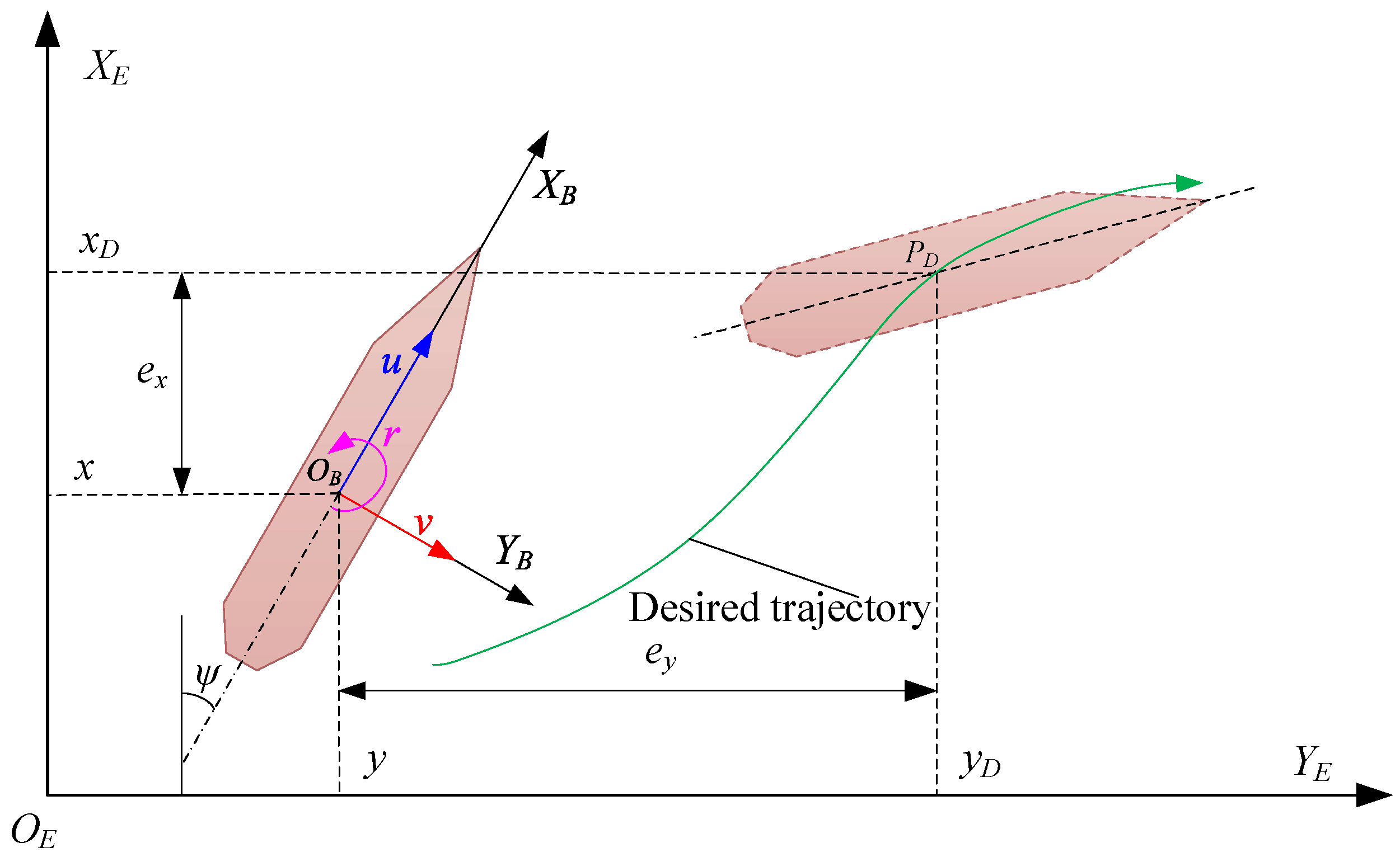
Figure 2.
Networked control block diagram for the USV.
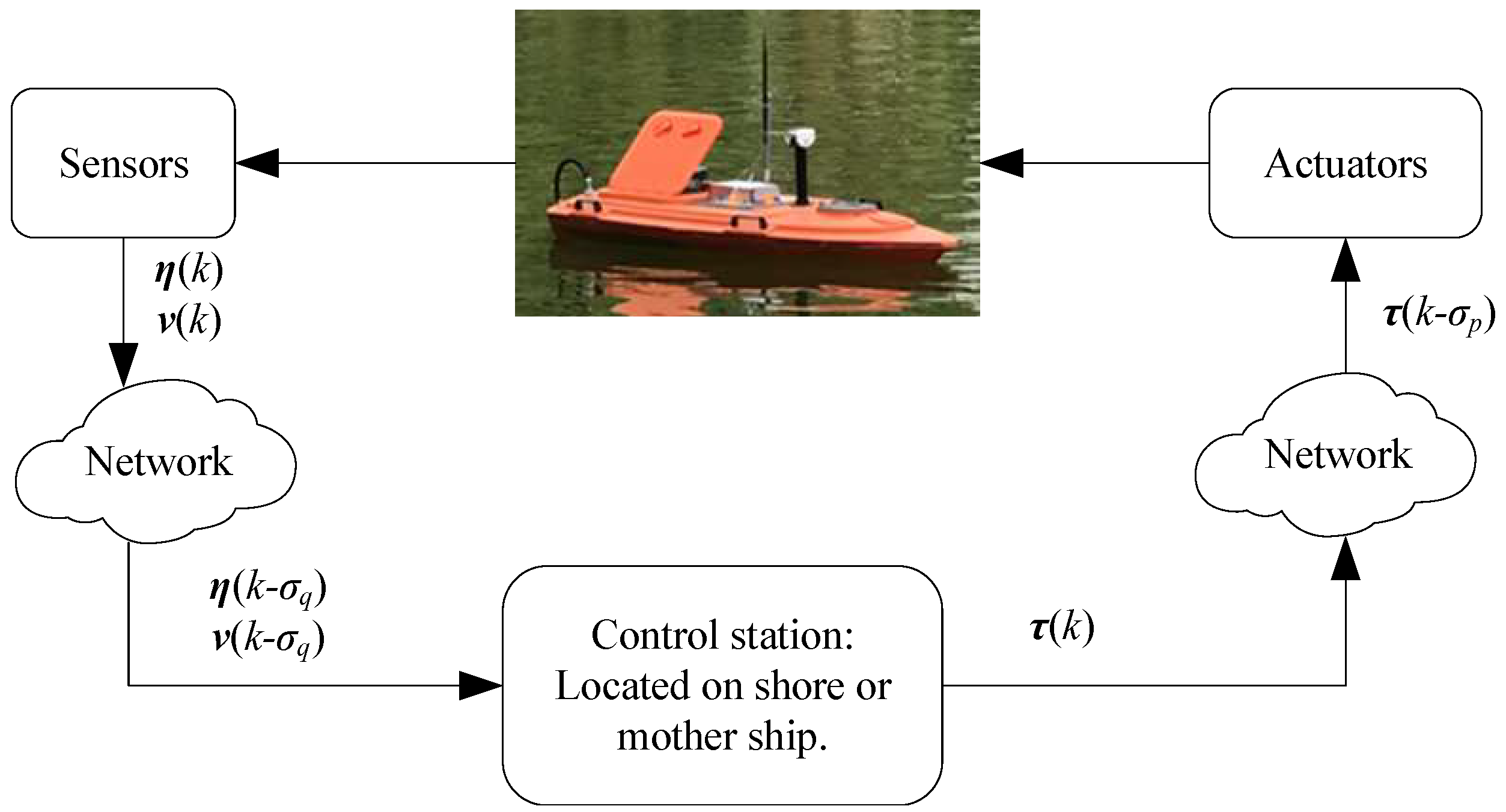
Figure 3.
The architecture of networked predictive control scheme for the USV.
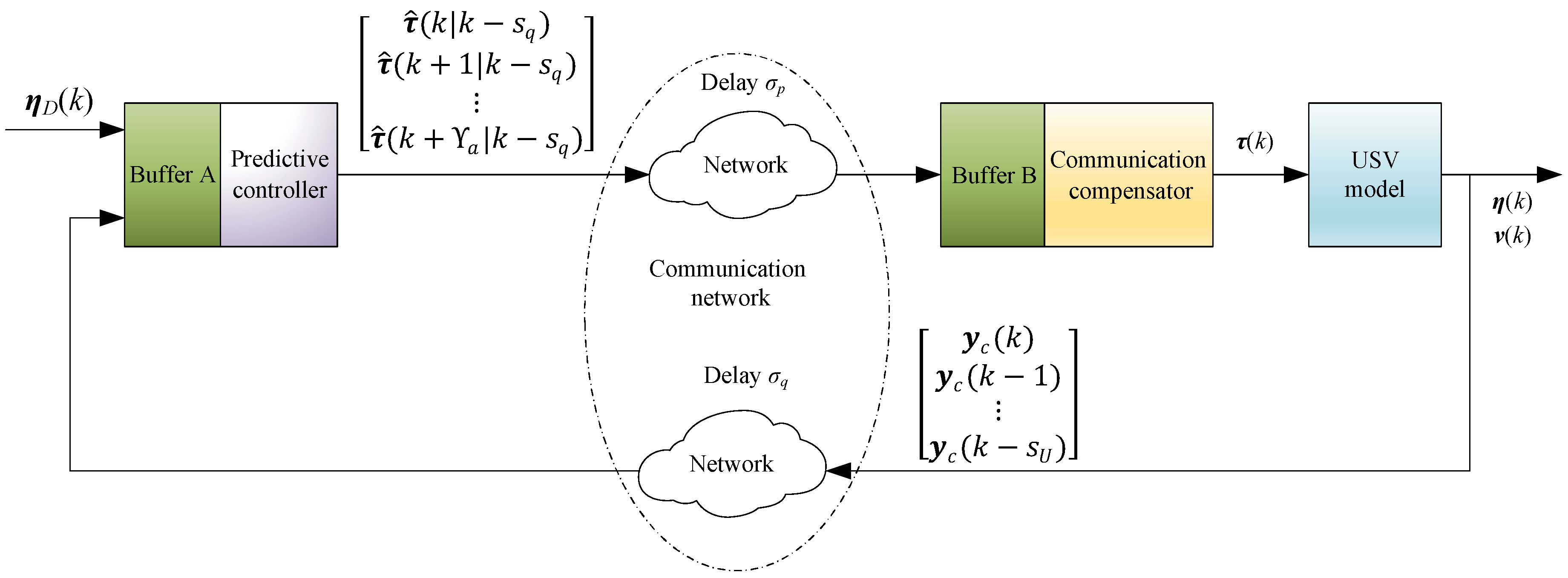
Figure 4.
Trajectory tracking curve of the USV in plane.
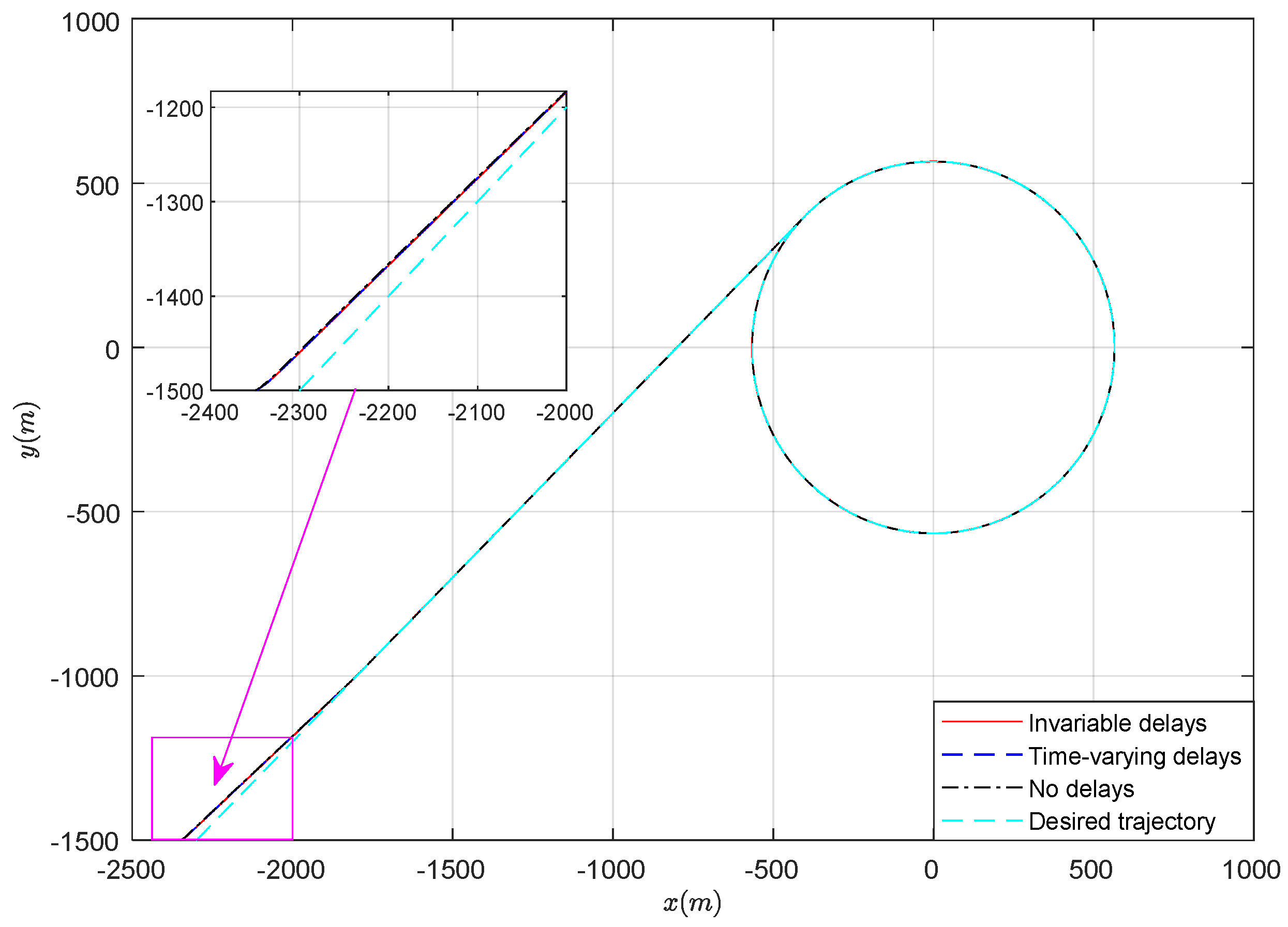
Figure 5.
Evolution of the tracking curve in the x direction.
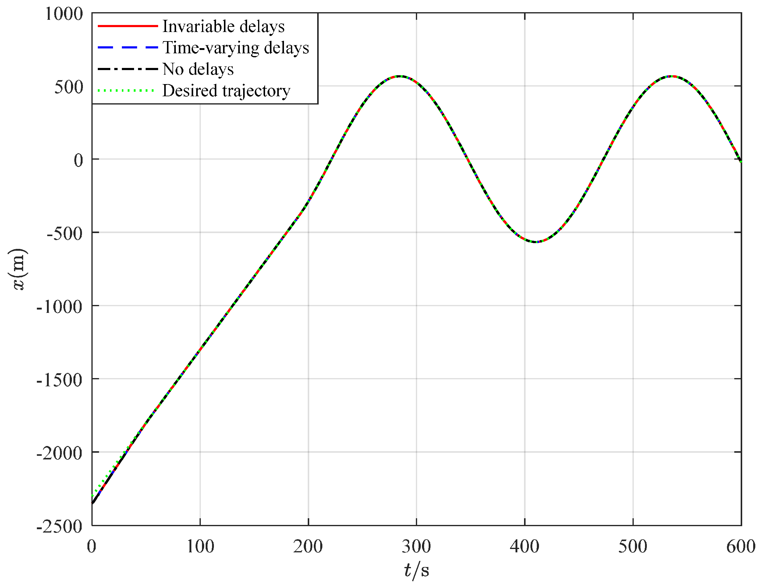
Figure 6.
Trajectory tracking curve in the y direction.
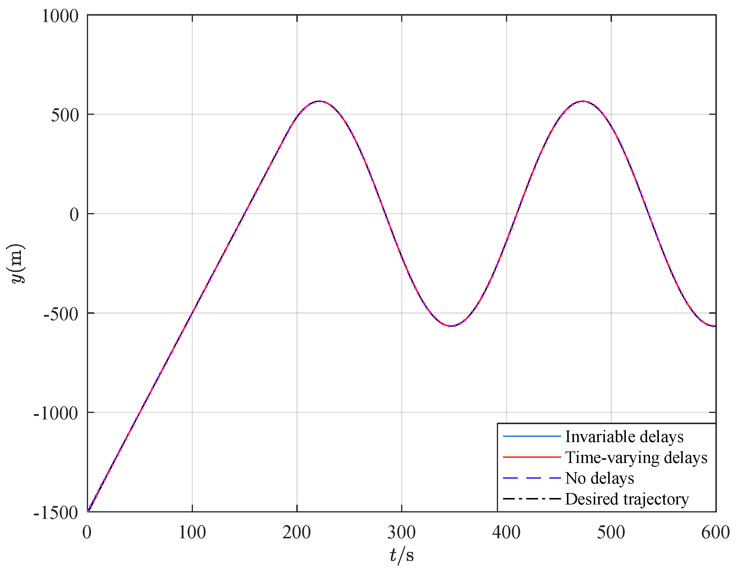
Figure 7.
Evolution of the position tracking error in the x direction.
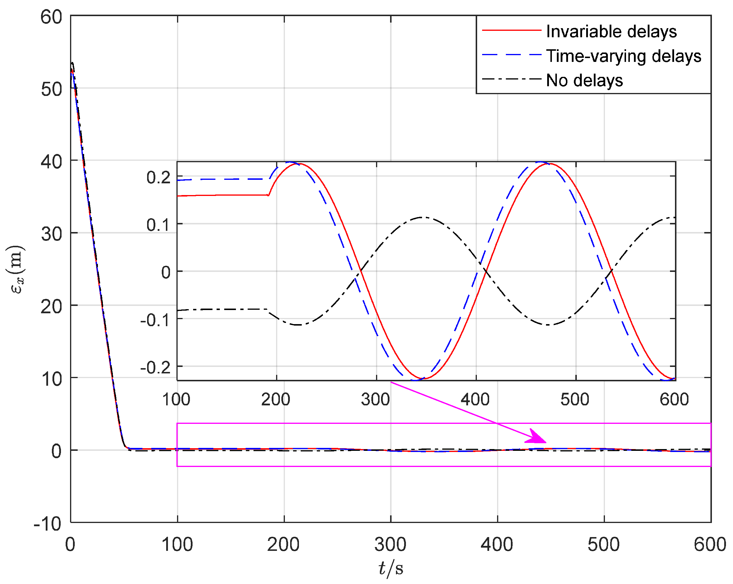
Figure 8.
Position tracking error in the y direction.
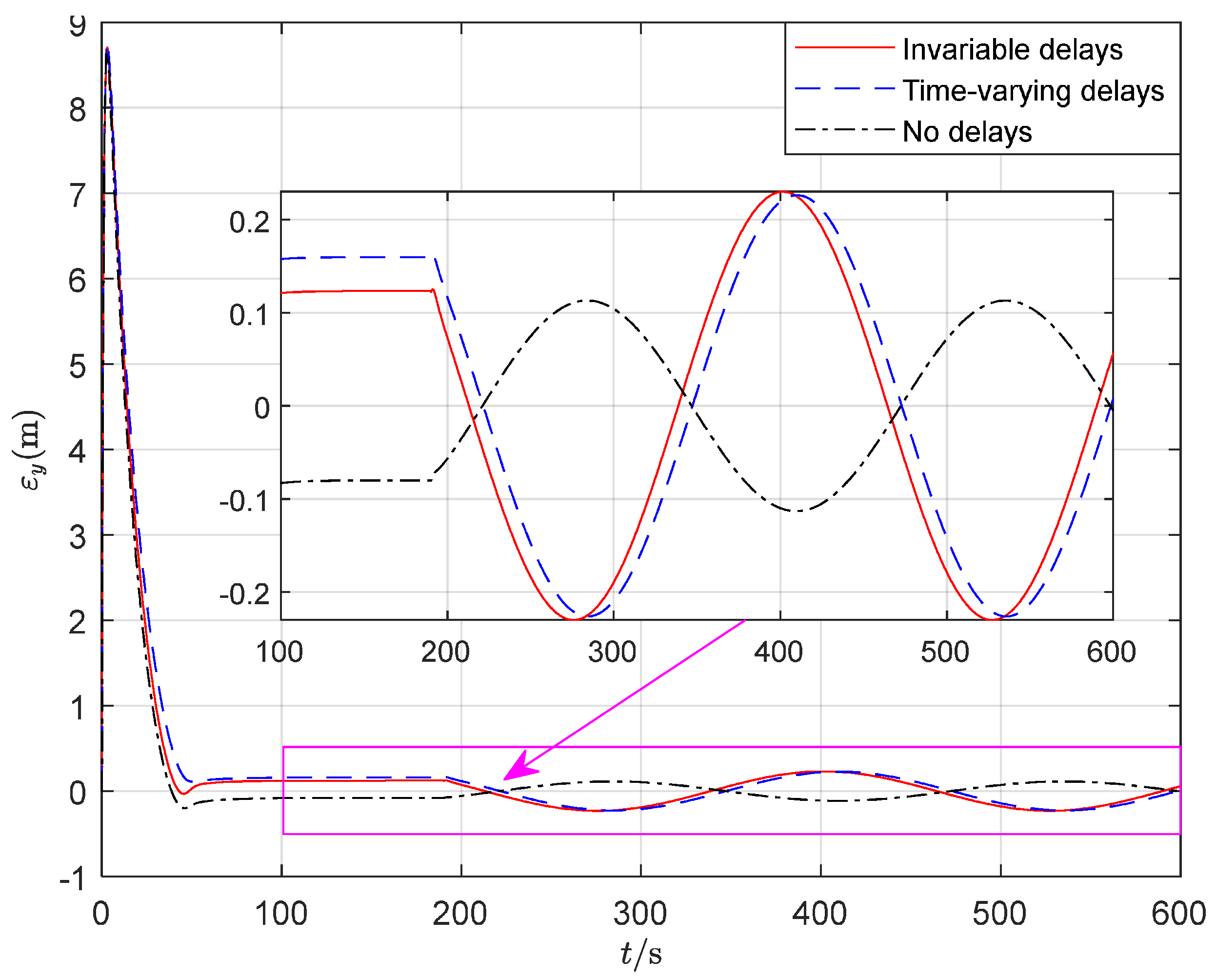
Figure 9.
The velocity changes over time.
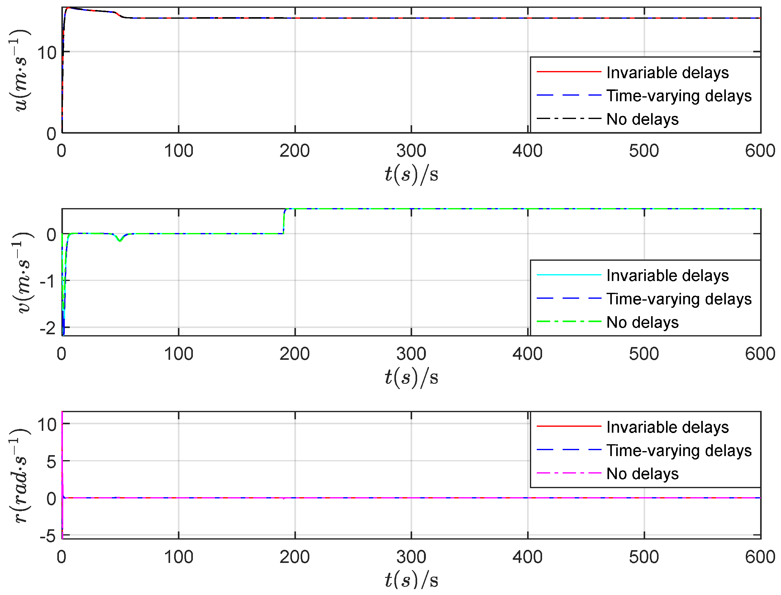
Figure 10.
The control input.
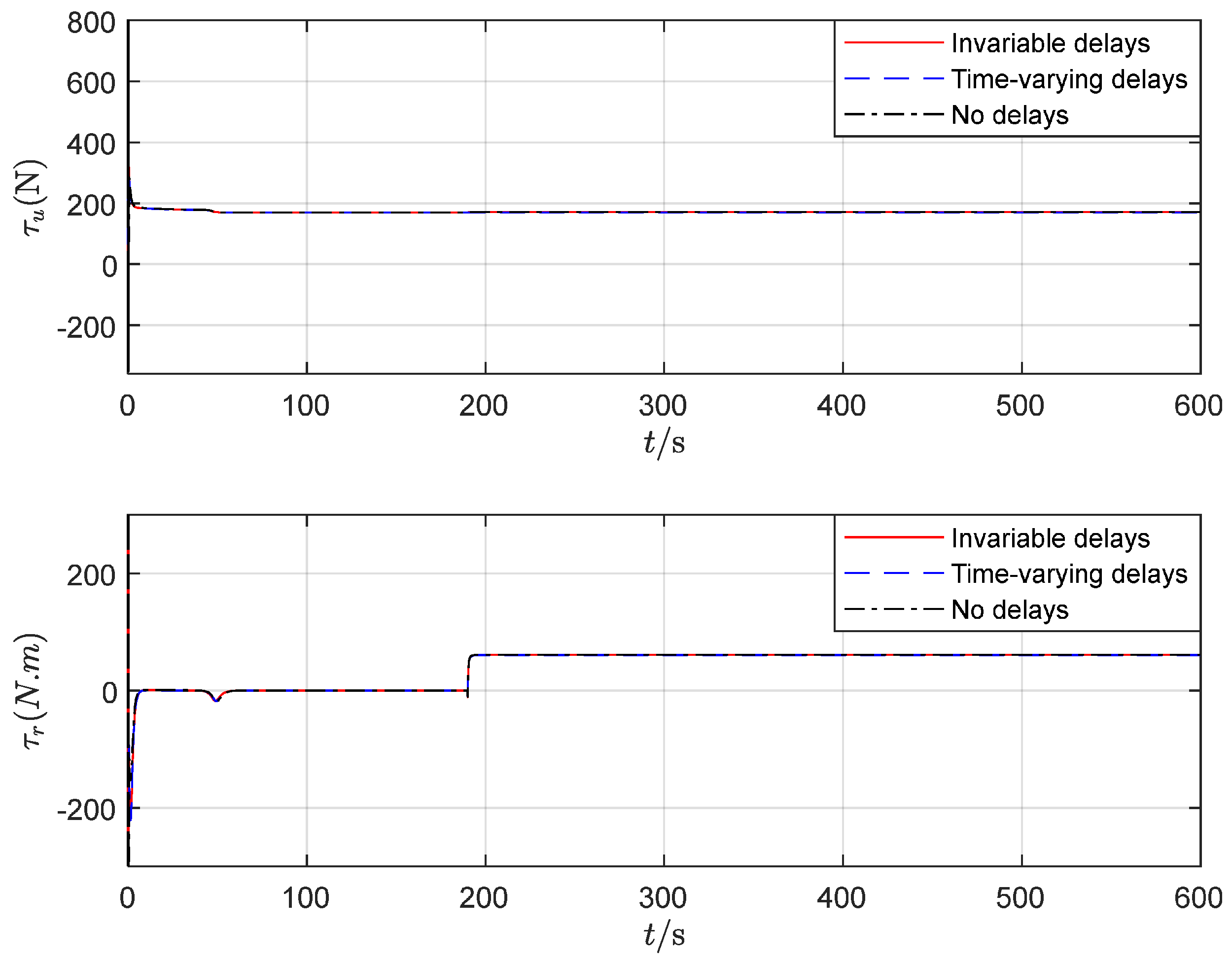
Figure 11.
The random delay (Case 3).
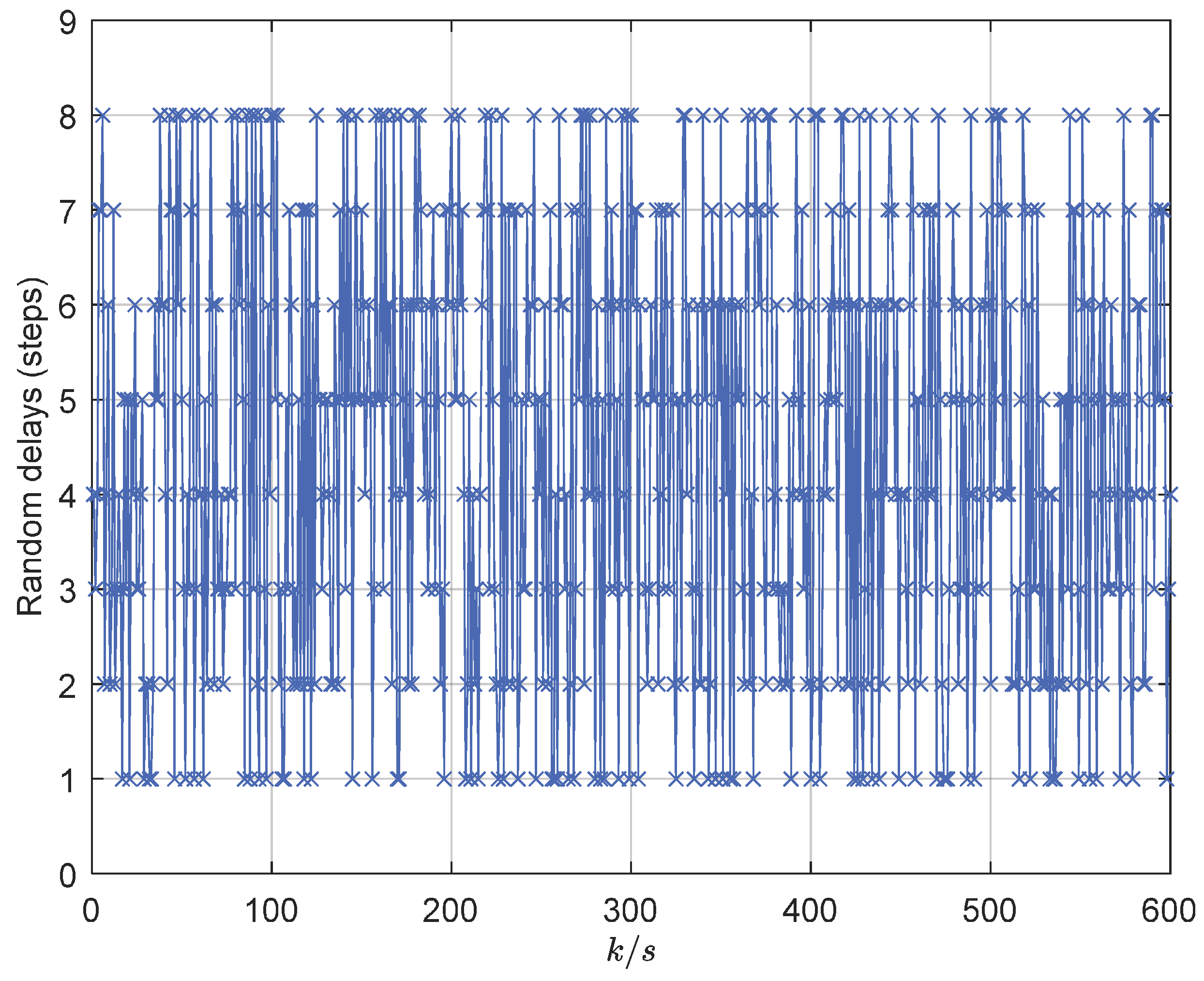

Table 1.
Model parameters of USV.
| Parameter | Value | Unit |
|---|---|---|
| m | 23.8 | [kg] |
| L | 1.225 | [m] |
| 25.8 | [kg] | |
| 33.8 | [kg] | |
| 2.76 | [kg] | |
| 12 | [kg/s] | |
| 17 | [kg/s] | |
| 0.5 | [kg/s] |
Table 2.
Control parameters.
| Variable | Value |
|---|---|
| 10.5 | |
| 10 | |
| 6 | |
| 1.05 | |
| 1.15 |
Table 3.
Mean absolute errors in x and y directions.
| Cases | MAE (x) | MAE (y) |
|---|---|---|
| Without delays | 22.4433 | 3.4866 |
| Invariable delays | 22.5066 | 3.5197 |
| Random delays | 22.77671 | 3.8380 |
Disclaimer/Publisher’s Note: The statements, opinions and data contained in all publications are solely those of the individual author(s) and contributor(s) and not of MDPI and/or the editor(s). MDPI and/or the editor(s) disclaim responsibility for any injury to people or property resulting from any ideas, methods, instructions or products referred to in the content. |
© 2024 by the authors. Licensee MDPI, Basel, Switzerland. This article is an open access article distributed under the terms and conditions of the Creative Commons Attribution (CC BY) license (http://creativecommons.org/licenses/by/4.0/).
Copyright: This open access article is published under a Creative Commons CC BY 4.0 license, which permit the free download, distribution, and reuse, provided that the author and preprint are cited in any reuse.


