1. Introduction
Microfluidics is the field that studies the handling of very small amounts of fluids. It has seen an exponential growth allowing for its application in a wide variety of scientific and technological fields including biology, chemistry, medicine and engineering. The precise manipulation of fluids using small channels has produced miniaturized systems that have been applied to medical diagnostics, disease detection and chemical and biological analyses [
1,
2,
3]. However, the selection of materials and fabrication techniques is a critical factor as it influences critically the efficiency, economic viability and the accessibility of these microsystems.
Early microfluidic devices were built on silicon or glass using microelectronic techniques including lithography and etching producing devices with high precision, highly miniaturization and quality but at a high cost and very strict environmental requirements such as the use of clean rooms.
Once microfluidic devices proved their worth, the development of novel applications growed very rapidly thanks to the use of new materials and simpler and cheaper microfabrication methods.
Computer controlled machining (CNC) and laser machining are currently used on polymer substrates. For instance, computer-controlled machining (CNC) and laser machining are currently used on a wide variety of polymeric substrates.
These techniques can produce microstructures in a fast and precise manner rendering them ideal to produce prototypes or small series of devices. CNC micromachining is especially useful when working with thermoplastic substrates as it is a good compromise between substrate costs, fabrication speed and surface quality. On the other hand, laser micromachining allows for an even greater precision. Both technologies call for the use of equipment whose cost ranges from medium to high.
Additionally, methods such as microembossing and microinjection continue to be essential for the mass production of microfluidic devices. These processes enable the fabrication of devices featuring high-quality surfaces and high reproducibility but require a much higher investment in specialized machinery to produce the required molds.
However, this approach is mainly preferred for industrial production as this higher investment is dampened by spreading it in the high yield of mass-produced devices.
Fabrication methods based on layers or multilamination have recently become popular due to their ability to build devices with complex geometries and convoluted designs as these devices cannot be produced at a reasonable cost using other methods. Multilamination involves making a 3D structure layer by layer using a single or several materials that can be different or the same.
This involves several micromachining techniques capable of defining different motifs and structures in each layer.
The ensuing 3D structure can integrate different functionalities such as microfluidic channels, electronic circuits, sensors and other detection systems. Making devices layer by layer permits the construction of devices featuring material gradients or devices with adjustable mechanical or chemical properties, a feature that may be especially valuable in biomedical and diagnostic applications.
However, these approaches require specialized thermal compression equipment like adjustable presses with hot plates that may raise the initial investment in infrastructure.
3D printing is an emergent technology in the fabrication of microfluidic devices. It involves methods such as stereolithography (SLA), fused deposition modeling (FDM), selective laser sintering (SLS) and multijet modeling (MJM), that produce complex 3D structures one layer at a time. Each of these methods has its own combination of cost, processing speed, resolution and design complexity.
For instance, SLA and SLS provide the high resolution and precision needed to produce complex microfluidic structures but at a relatively high cost.
On the other hand, FDM is a more economic option but with some limitations in resolution and surface quality [
4,
5].
Although 3D printing is considered a layer-by-layer additive manufacturing technology it is key to differentiate it with respect to other layer technologies such as multilamination.
In 3D printing the resulting structure is produced by the segmentation of the object in layers. Each layer is formed and fused with the previous layer in a continuous printing process.
In multilamination, layers are fabricated separately and then aligned and processed by different ways (thermo compression, sinterization, gluing, etc.) so all the layers are fused in a single and final 3D object.Low-temperature co-fired ceramics (LTCC) and cyclic olefin copolymer (COC) are two materials widely used to fabricate microfluidic devices using the multilamination approach. Both these materials and the associated technology show advantages and disadvantages depending on the application. Although development costs are much lower than the methods described above, they are still out of reach for researchers with limited research funds.
LTCC technology allows for the integration of microchannels, valves, sensing elements and signal-processing circuitry. This approach yields robust and precise microfluidic systems that have been applied to biomedical, diagnostic and chemical problems.
Although LTCC-based microfluidic systems are versatile, they require special materials with adequate thermal compatibility such as substrates, inks, pastes, etc. and costly equipment like CNC machines, presses and furnaces and this may hamper its use to obtain low-cost prototypes [
6].
COC, a high-performance amorphous copolymer offers an exceptional degree of transparency and biocompatibility.
Changing the composition of the copolymer by varying the proportion of the monomers, materials with different vitreous transition temperatures can be produced.
If COC layers with different vitreous transition temperatures are used, a complex microfluidic structure can by produced in a simple manner by multilamination using a thermocompresion process.
These characteristics make COC an ideal material for applications that call for visual, optical or biological interactions [
7,
8]. When compared to LTCC, COC fabrication processes are simpler and quicker, but these processes also call for CNC machines, hot-plate precision presses or ultrasound lamination machines [
9].
The present work addresses the use of photocured resins-based 3D printers combined with multilamination without thermocompression as a promising option for the fabrication of tailor-made, low-cost microfluidic devices featuring small channels for specific applications in the analytical chemistry field.
Additionally, 3D printing does not require additional costly equipment rendering this technology more accessible than LTCC or COC-based fabrication methods. In this way it is possible to make available to all laboratories of the world low-cost technologies to spurring innovation in the field of microfluidics [
10,
11,
12].
The 3D printing techniques based on stereolithography (SLA) and digital light processing (DLP) used in this work are more accessible than other configurations such as multiple jet printing (MJP) [
13,
14].
2. Materials and Methods
3D printing was made with an Epax printer model X1 (Epax, Morrisville, North Carolina, U.S.A.), using 140 mm (5.5 inches) LCD SLA technology with 2K resolution (2560 x 1440 pixels) and 40W power compatible with 405 nm photosensitive resins. Resins used were ELEGOO ABS-Like Photopolymer Resin (ELEGOO, Shenzhen, China) in four tints: clear, red, black and green. A translucent resin supplied by ANYCUBIC (Shenzhen, China) was also used. The program Fusion 360 (Autodesk, San Francisco, California, U.S.A.) was employed to develop the 3D structures. The configuration and generation of the files fed to the 3D printer were produced with the program ChiTuBox Basic 1.9.4 (ChiTuBox, Shenzhen, China), for SLA/DLP/LCD printers. Data and dimensions were analyzed with OriginPro 2023B software (Northampton, Massachusetts, U.S.A.). Models were post-cured in a 405 nm curing box supplied by SUNLU (SUNLU, California, EE. UU.), featuring a rotating plate and a 60 W lamp.
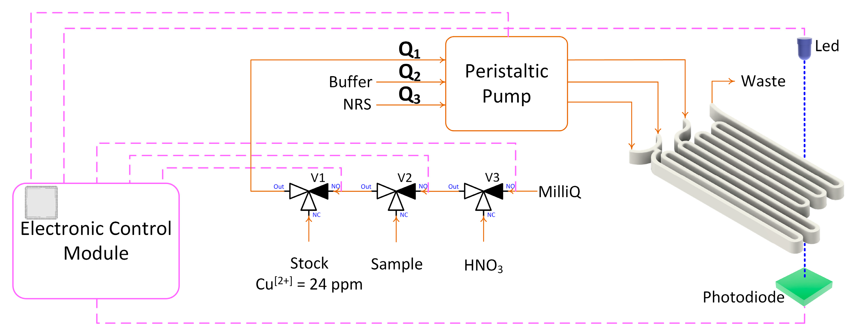
All reagents used throughout this work were analytical grade. The stock copper solution for ICP (1000ppm), the disodium phosphate (Na2HPO4), the monosodium phosphate (NaH2PO4) and the nitric acid (HNO3) were supplied by Sigma-Aldrich (Darmstadt, Germany). The 3-Hydroxy-4-nitroso-2,7-naphthalenedisulfonic acid disodium salt (NRS) was supplied by Fluka (Honeywell, North Carolina, U.S.A.). Working copper (II) solutions were prepared by successive dilutions from a 10-ppm stock standard copper (II) solution. A phosphate buffer solution (adjusted to pH 6.6), a 1.1 mM disolution of the NRS reagent and a 0.01M HNO3 solution were prepared using MilliQ water.
Transmittance was measured with a UV-Vis spectrophotometer series AM1706003 (Shanghai Metash Instruments, Shanghai, China). The microfluidic modules printed in resin were designed according with a lock & key configuration [
15] [Versatile Lock and Key Assembly for Optical Measurements with Microfluidic Platforms and Cartridges. Oriol Ymbern, Miguel Berenguel-Alonso, Antonio Calvo-López, Sara Gómez-de Pedro, David Izquierdo and Julián Alonso-Chamarro, Anal. Chem. 2015, 87, 1503−1508]. DOI: 10.1021/ac504255t] featuring a 505 nm light emitting diode (Roithner Lasertechnik B5B-433-B505, Farnell, Spain) and a Hamamatsu S1337-66BR photodiode (Farnell, Spain).
NResearch three-way microvalves 161T031 (NResearch, Switzerland) were used for all fluid-handling operations including multicommutation, stock solutions preparation by automatic dilution, as well as sample, nitric acid cleaning solution and water intake. Fluids were impelled by an ISMATEC peristaltic pump ISM852A-115V60H (Cole-Parmer, Vernon Hills, Illinois, U.S.A.) connected to 1.2 mm Tygon (1Ismatec, Switzerland) and 0.8 mm i.d. polytetrafluorethylene (PTFE) (Tecnyflour, Spain) tubing.
The electronic control module was designed using the software EAGLE 9.3.1 (Autodesk, San Francisco, California, U.S.A.). The printed circuit of the module was designed using the software JLC (Shenzhen JLC Electronics Ltd., Shenzhen, China). The module was assembled and soldered by the authors. The main control element of the module is a programmable system on a chip, specifically the integrated circuit PSoC 5 CY8C5868AXI-LP035 (Infineon, Neubiberg, Germany).
Figure 1 shows the general diagram of the experimental setup used to test the microfluidic devices.
3. Results
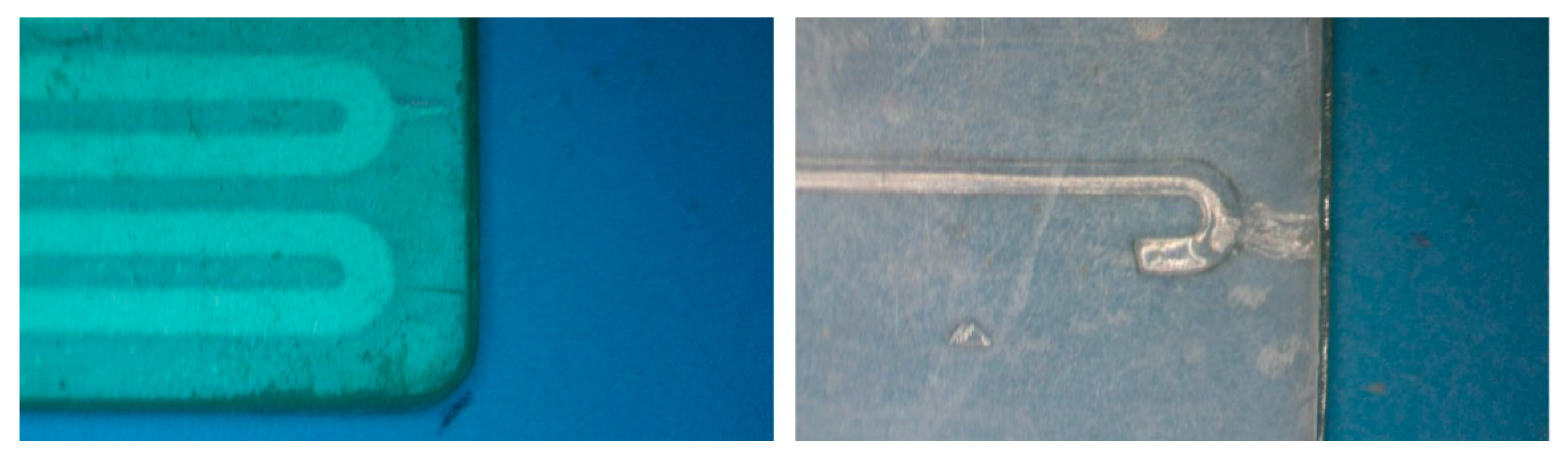
All 3D prints were made in an area approximately 54x44 mm. Single block prints were 3mm thick. The resin inside the channels was removed by injecting isopropyl alcohol using positive pressure via a syringe. To avoid photopolymerization of the resin inside the channels during printing, it was necessary to reduce the exposure time in all layers to the minimum recommended by the manufacturer. The reduction in exposure times cause insufficient adhesion between the layers, which, together with the viscosity of the uncured resin and the pressure applied to remove it from the channels, caused the separation of the layers and leaks in microstructures whose channels were greater than 50mm in length or microstructures featuring sharp turns intended to act as a mixer.
Figure 6 shows some of the observed leaks.
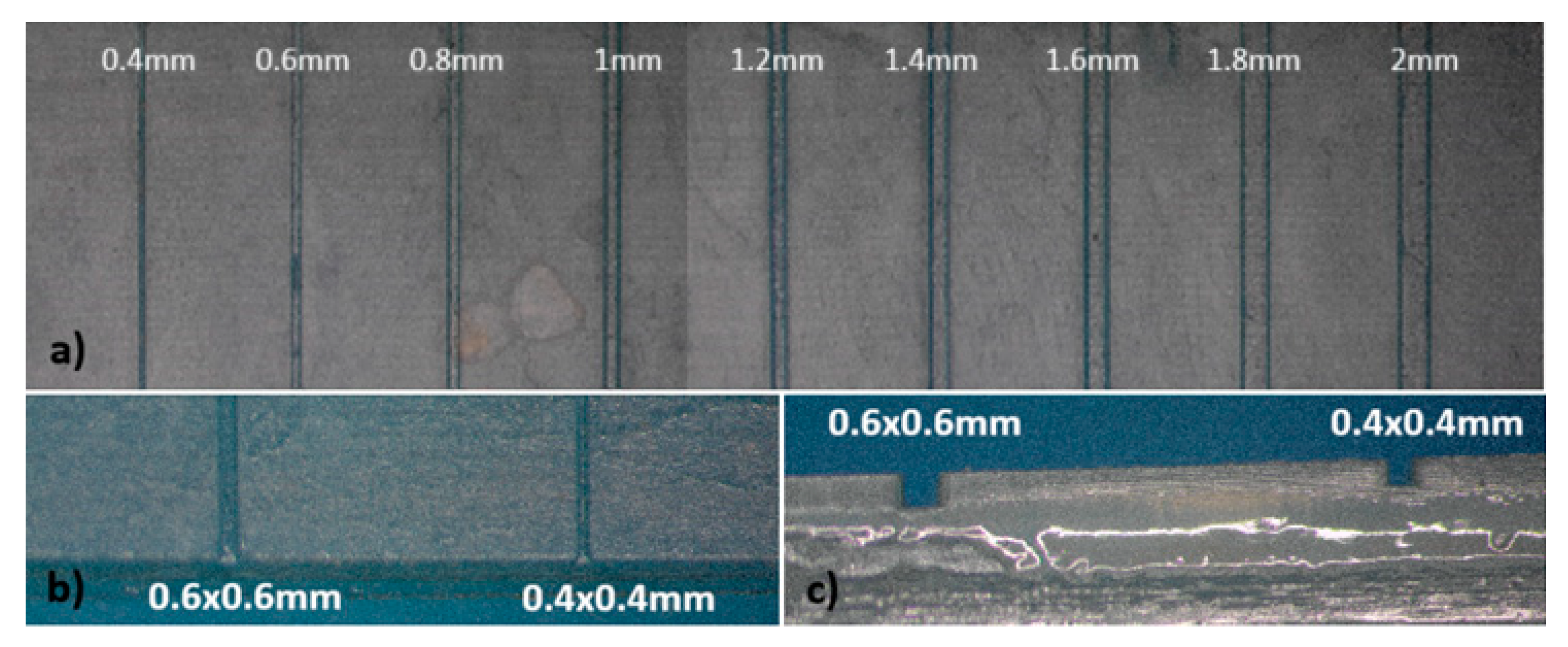
For the fabrication of devices by the multilamination based approach, the dimensions of the channel designed were initially 2x2mm, decreasing them in 0.2 mm steps until reaching channels of 0.2x0.2mm. The overall structure is composed of two blocks, one of them incorporating the opened microfluidic channels and the other one acting as a cover block. In
Figure 7 the different channels without cover on one of the blocks can be seen. Channels with dimensions equal to or greater than 0.4mm presented good definition and repeatability.
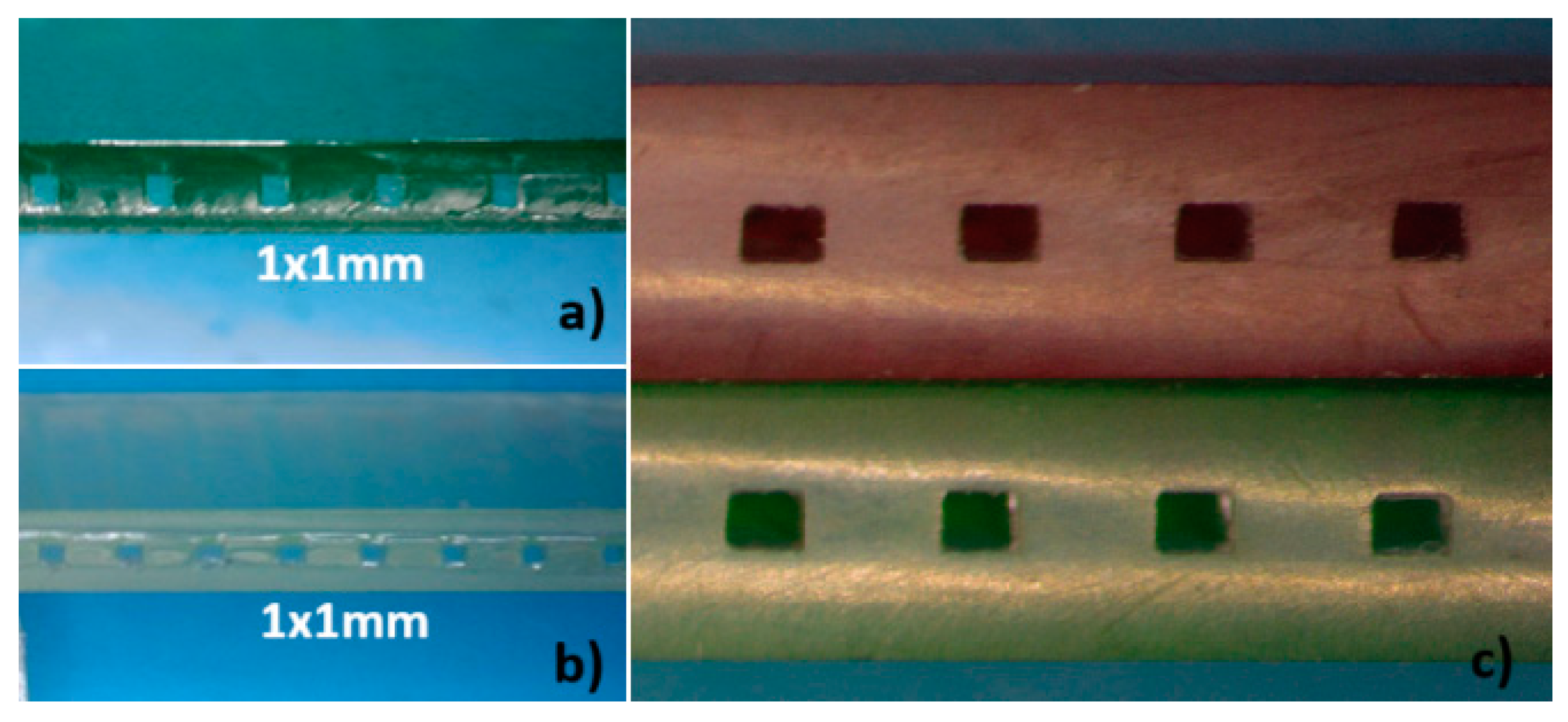
To evaluate the microfluidic structure produced using this method several micro-channels with identical dimensions were printed next to each other on the first block. Once both elements were joined, the resulting monolithic structure was cut and the cross-section area of each channel was measured at various points.
Figure 8 shows photographs of the cross sections of several printed and multilaminate monolithic structures obtained with different resins: a) ELEGOO green resin; b) ELEGOO transparent resin. In the amplified photograph shown in c) you can see that the joining of the two elements results in a single monolithic block where the interface between them is not visible.
It was noted that the resin used to join the two elements penetrated the microchannel causing a decrease in its height. The mean height reduction was 0.135 mm, with a standard deviation of 0.02 mm. The thickness of the sealing polymer layer after photocuring is no larger than 0.150mm. This reduction must be considered during the design process to achieve the desired channel sizes.
The microfluidic structures developed with this methodology were ready for use after curing the resin layer used to join the two elements.
The smallest channels constructed were 0.4x0.4 mm, regardless of the resin used, yielding leakage-free microfluidic platforms.
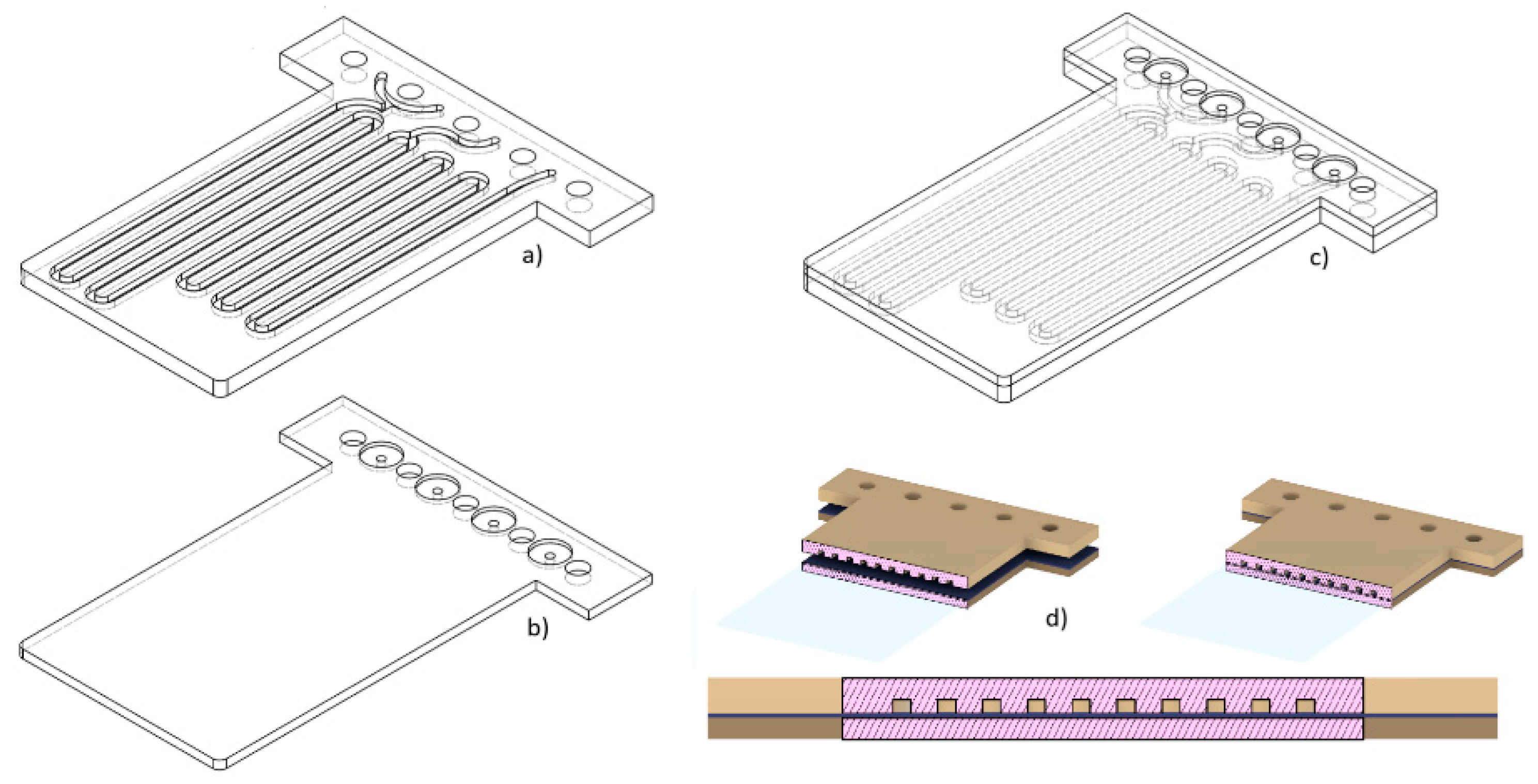
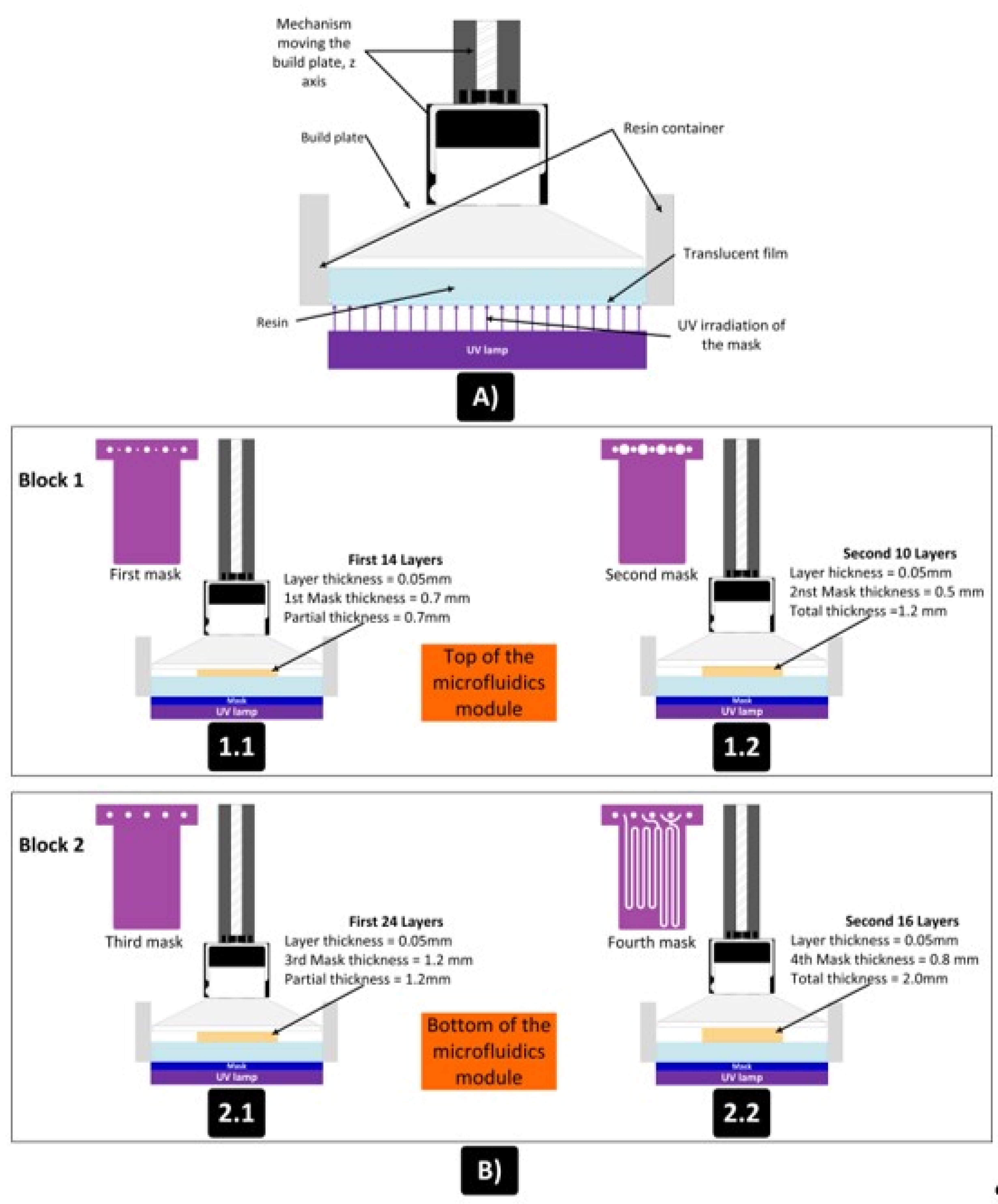
Figure 9 shows the design, distribution of masks and number of layers used for the manufacture of the two blocks of the device shown in
Figure 5. A layer thickness of 50 µm was used, so the final design had a total thickness of 3.2mm. The microfluidic platform comprised three fluidic inlets, two confluence points, two meander-based mixers and one outlet.
For analytical applications using optical measurements, it is important to integrate detection cells into microfluidic platforms whose optical path can be easily modified.
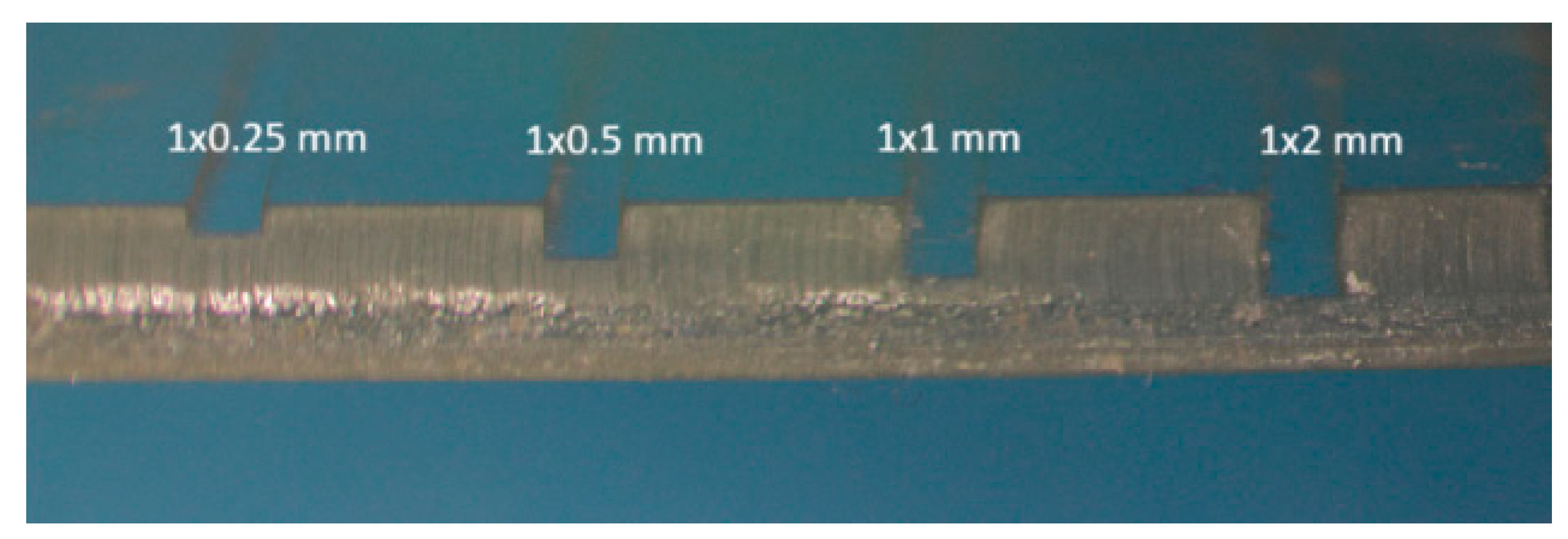
Considering that the detection cell is formed by a zone of the microfluidic channel, the fabrication methodology described above allows to easily increase the length of the optical path by varying the channel height. In this way, the dead volume of both the detection cell and the microfluidic system can be reduced. Both factors allow to limit sample dilution enhancing the sensitivity of the measurements. In
Figure 10, different fabricated channels 1mm wide, with heights from 0.25 mm to 2mm, can be seen.
Modifying the height/width ratio of the microchannels to increase the optical path has other advantages. For instance, microchannels with ratios greater than 1 show greater resistance to deformation and are less susceptible to occlusion by the resin used as a sealant during the multilamination process.
Figure 11 shows the transmittance spectrum obtained with 3mm-thick plates using the four ELEGOO resins (transparent, green, red, black) and the translucent ANYCUBIC resin.
The maximum transmittance was obtained at a wavelength of 505 nm using the green and transparent resins. In any case, the transmittance measured for all resins studied were below 30%. This fact seems to be related with the surface roughness of the first layer impressed in contact with the build plate.
Additional experiments performed with the transparent ELEGOO resin once the rough faces had been polished show a transmittance better than 60% for wavelengths higher than 425 nm. As can be seen, the polishing step is critical to enhance signal measured and then sensibility and detection limit of the analytical microsystem.
To corroborate the usefulness of the developed 3D printed microfluidics using the described multilamination process, a microfluidic platform described in the Methods and Materials section (
Figure 5 and
Figure 9) was designed with a cross-sectional channel of 0.8x0.8mm for colorimetric determination of copper previously used by Guevara [
3].
This microfluidic platform was incorporated to a multiconmutation flow system microanalyzer performing automatic sampling and autocalibration procedures which are like those described in [
3].
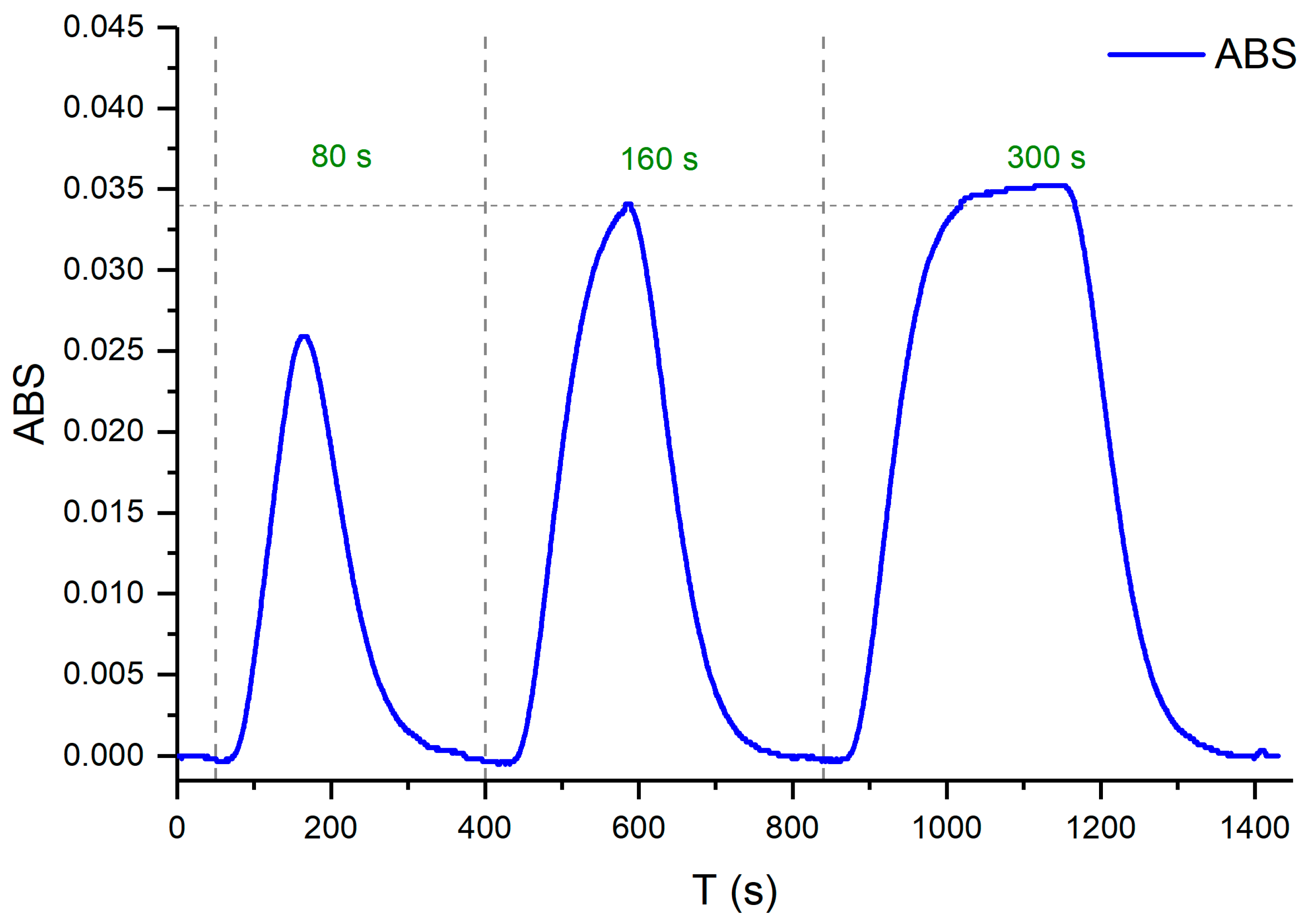
Working at constant flow conditions, the sample volume injected depends on the actuation time of the 3-way valves used to select between sample/standard solution or carrier solution by commutation. To obtain robust microfluidic platforms not affected by slight changes in the experimental conditions, it was necessary to select a sample injection time that allowed the analytical signal to rise to its steady state.
Figure 12 shows the results of the experiment performed at a fixed flow rate of 1.4 ml/min in each channel (Q1, Q2 y Q3) to determine the optimal injection time. The sample injection time selected was 120 s.
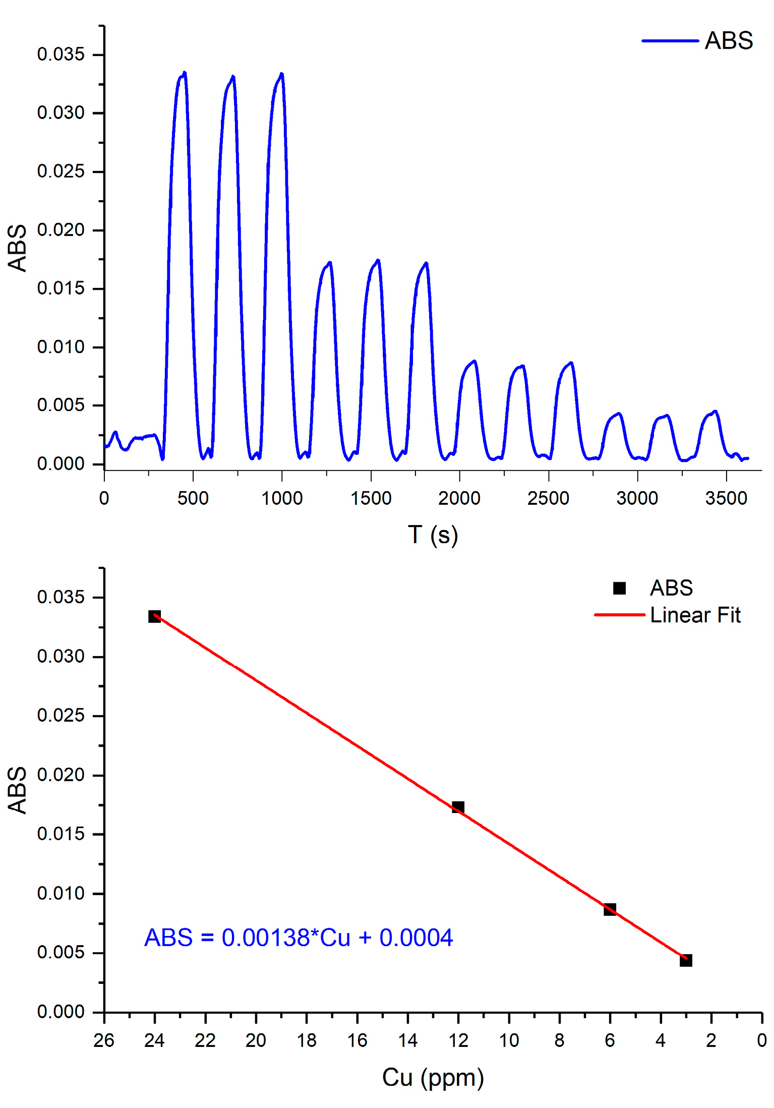
Finally, the multiconmutation approach allows to perform an automatic autocalibration procedure by “in-situ” generation of different standards solutions from a single concentrated stock solution.
Analytical features derived from the calibration plot obtained in the experimental conditions fixed after the optimization process shows a linear response in the range between 3 and 24 ppm of copper (II) with a correlation coefficient r2 >0.999.
Figure 13 shows the analytical signals obtained during the autocalibration cycle featuring triplicate measurements.
To assess the reproducibility of the analytical signals provided by different micro-fluidic platforms operating at identical conditions, four of them were tested over a twelve-week period. All of them yielded similar results. The dimensions, polymeric resin, coloring, and structural integrity (no breakage or leakage) were maintained in all cases. The analytical results obtained with the devices fabricated with the 3D printing technology were comparable to those provided by microfluidic platforms made of COC using the multilamination approach. The main difference was the cost, as the micro-fluidic platforms described here were more affordable in terms of both materials and needed infrastructure.
4. Conclusions
The methodology described for the fabrication of fluidic systems using commercial low-cost UV 3D printers and resins allows for the rapid construction of microfluidic platforms with longer microchannels and more complex pathways. When designing the microchannels, an average reduction of 0.135 mm in the channel height should be considered. This reduction is caused by the resin deposited as an adhesive for bonding the two halves that constitute the microfluidic platform. The described method achieved better results than printing the entire platform in a single block, which is viable for short channels but presented issues of lack of rigidity and a high probability of breakage and leakage when attempting to remove the uncured resin from the microfluidic structures.
The microfluidic modules fabricated for copper detection were extensively tested, and it was observed that their dimensional integrity was maintained, and no leakages occurred. Their performance was identical to that of the platforms constructed with COC. The use of flat surfaces, along with the quality of the adhesion of the layers in the post-processing stage, opens the possibility of combining materials and technologies for future analytical flow applications.
The methodology described for the fabrication of fluidic systems using commercial low-cost UV 3D printers and fotoresins allows for the simple and rapid construction of microfluidic platforms with complex and longer microchannel pathways. The method proposed, based on multilamination approach, provides better results than the monolithic printing of the entire platform due to the difficulty to evacuate the uncured resin filling the microcanales.
A multiconmutation flow system microanalyzer for copper detection incorporating the microfluidic platforms fabricated were evaluated and optimized. It was observed that their operational performance and analytical features were identical to that of the platforms constructed with COC. The obtaining of flat surfaces with enhanced optical transmission obtained by polishing along with the quality of the adhesion of the layers in the post-processing stage, opens the possibility of combining materials and technologies for future analytical applications.
Author Contributions
Conceptualization, V.E.M.A., H.C.F.; methodology, V.E.M.A.; software, V.E.M.A, H.C.F.; validation, K.V.G.A., V.E.M.A. H.C.F and P.C.; formal analysis, V.E.M.A, H.C.F. and K.V.G.A.; writing—original draft, H.C.F., V.E.M.A. and K.V.G.A.; writing—review and editing, H.C.F., F.V.P., and J.A.-C.; supervision, F.V.P., and J.A.-C.; funding acquisition, F.V.P., and J.A.-C
Funding
The authors acknowledge Met-Mex Peñoles S.A. de C.V. and the Consejo Nacional de Humanidades, Ciencias y Tecnologías of Mexico (CONAHCYT) for financial support. The authors also would like to thank the financial support from the Spanish Ministry of Science and Innovation through the project PID2020-117216RB-I00 and Catalan government through the project 2021SGR00124.
Acknowledgments
The authors acknowledge to Tecnológico Nacional de México (TecNM), Instituto Tecnológico de la Laguna.
Conflicts of Interest
The authors declare no conflict of interest. The funders had no role in the design, collection, analyses, and interpretation of data of the study, nor in the writing of the manuscript or in the decision to publish the results.
References
- Sanders, G.; Manz, A. Chip-based microsystems for genomic and proteomic analysis. TrAC 2000, 19, 364–378. [Google Scholar] [CrossRef]
- Ibáñez-García, N.; Baeza, M.; Puyol, M.; Gómez, R.; Batlle, M.; Alonso-Chamarro, J. Biparametric Potentiometric Analytical Microsystem Based on the Green Tape Technology. Electroanalysis 2010, 22, 2376–2382. [Google Scholar] [CrossRef]
- Amatón, K.V.G.; et al. Microanalyser Prototype for On-Line Monitoring of Copper (II) Ion in Mining Industrial Processes. Sensors 2019, 19, 3382. [Google Scholar] [CrossRef] [PubMed]
- Scott, S.; Ali, Z. Fabrication Methods for Microfluidic Devices: An Overview. Micromachines 2021, 12, 319. [Google Scholar] [CrossRef] [PubMed]
- Juang, Y.-J.; Chiu, Y.-J. Fabrication of Polymer Microfluidics: An Overview. Polymers 2022, 14, 2028. [Google Scholar] [CrossRef] [PubMed]
- Couceiro, P.; Alonso-Chamarro, J. Microfabrication of monolithic microfluidic platform using low temperature co-fire ceramics suitable fluorescence imaging. Anal. Chem. 2017, 89, 9147–9153. [Google Scholar] [CrossRef] [PubMed]
- Berenguel-Alonso, M.; et al. Rapid prototyping of a cyclic olefin copolymer microfluidic device for automated oocyte culturing. SLAS Technol. 2017, 22, 507–517. [Google Scholar] [CrossRef] [PubMed]
- Calvo-Lopez, *!!! REPLACE !!!*; Ymbern, O.; Puyol, M.; Casalta, J.M.; Alonso-Chamarro, J. Potentiometric analytical microsystem based on the integration of gas-difussion step for on-line ammonium determination in water recycling processes in manned space missions. Anal. Chim. Acta 2015, 87, 26–32. [Google Scholar] [CrossRef] [PubMed]
- Prada, J.; Cordes, C.; Harms, C.; Lang, W. Design and manufacturing of a disposable, cyclo-olefin copolymer, microfluidic device for biosensor. Sensors 2019, 19, 1178. [Google Scholar] [CrossRef] [PubMed]
- Bhattacharjee, N.; Urrios, A.; Kang, S.; Folch, A. The upcoming 3D-printing revolution in microfluidics. Lab. Chip 2016, 16, 1720–1742. [Google Scholar] [CrossRef] [PubMed]
- Au, K.; Huynh, W.; Horowitz, L.F.; Folch, A. 3D-printed microfluidics. Angew. Chem. Int. Ed. 2016, 55, 3862–3881. [Google Scholar] [CrossRef] [PubMed]
- Gross, C.; Erkal, J.L.; Lockwood, S.Y.; Chen, C.; Spence, D.M. Evaluation of 3D printing and its potential impact on biotechnology and the chemical sciences. 2014.
- Taczała, J.; Czepułkowska, W.; Konieczny, B.; Sokołowski, J.; Kozakiewicz, M.; Szymor, P. Comparison of 3D printing MJP and FDM technology in dentistry. Arch. Mater. Sci. Eng. 2020, 101, 32–40. [Google Scholar] [CrossRef]
- Pagac, M.; et al. A review of vat photopolymerization technology: Materials, applications, challenges, and future trends of 3d printing. Polymers 2021, 13, 598. [Google Scholar] [CrossRef] [PubMed]
- Versatile Lock and Key Assembly for Optical Measurements with Microfluidic Platforms and Cartridges. Oriol Ymbern, Miguel Berenguel-Alonso, Antonio Calvo-López, Sara Gómez-de Pedro, David Izquierdo and Julián Alonso-Chamarro. Anal. Chem. 2015, 87, 1503−1508. [CrossRef]
- Tech, S. Siraya Tech Test Model. 2023.
- Electronics, C. Optimal Layer Exposure Time for Perfect Resin Prints - Tutorial Australia. 2023.
- Anycubic. Anycubic Photon Mono X - Google Drive. 2023.
|
Disclaimer/Publisher’s Note: The statements, opinions and data contained in all publications are solely those of the individual author(s) and contributor(s) and not of MDPI and/or the editor(s). MDPI and/or the editor(s) disclaim responsibility for any injury to people or property resulting from any ideas, methods, instructions or products referred to in the content. |
© 2024 by the authors. Licensee MDPI, Basel, Switzerland. This article is an open access article distributed under the terms and conditions of the Creative Commons Attribution (CC BY) license (http://creativecommons.org/licenses/by/4.0/).