Submitted:
20 December 2024
Posted:
20 December 2024
You are already at the latest version
Abstract
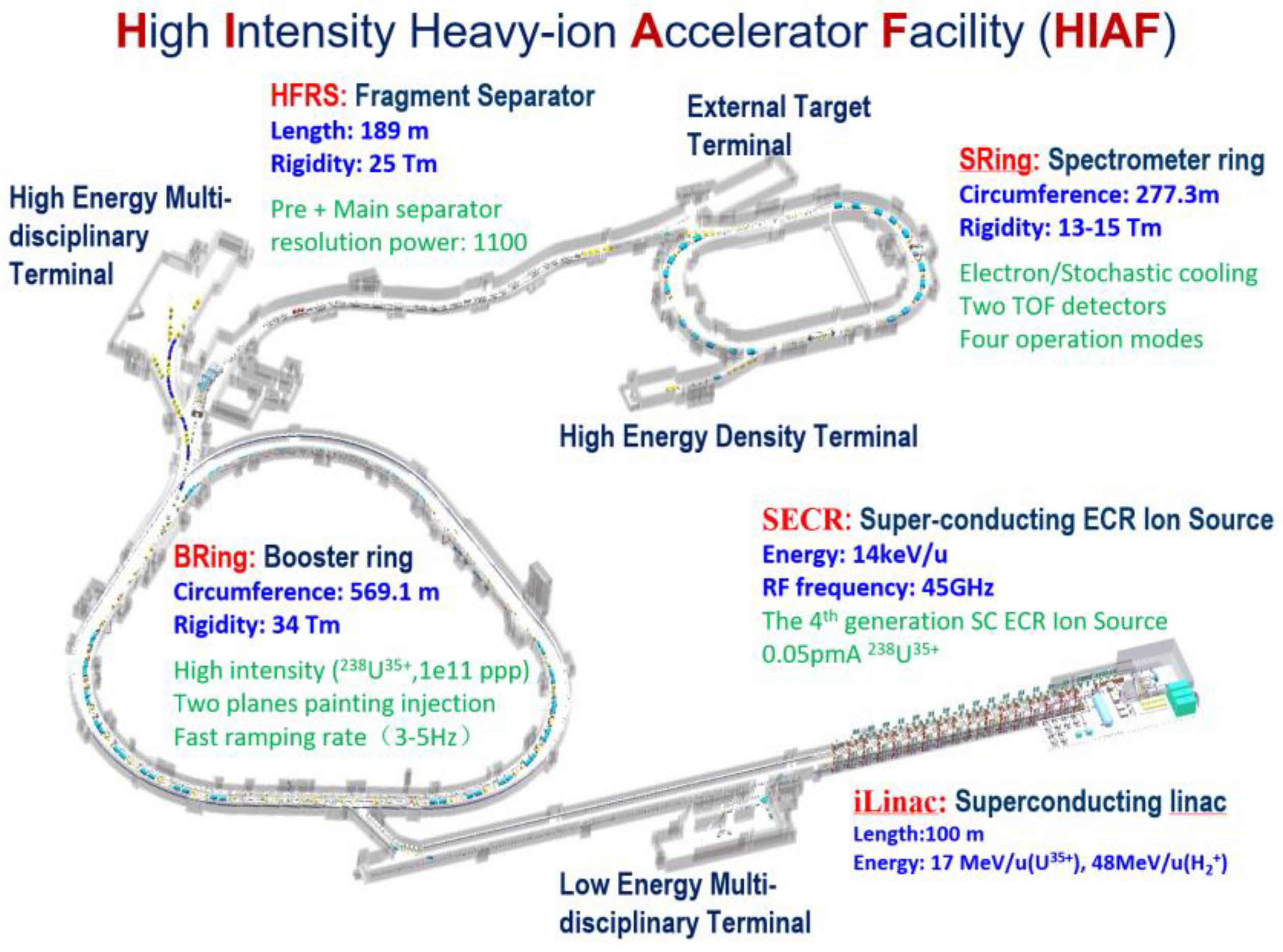
The High-Intensity Heavy-Ion Accelerator Facility (HIAF) is a significant national science and technology infrastructure project, constructed by IMP, to provide primary and radioactive intense beams for nuclear and related research. Large aperture, high-precision, and warm-ion superconducting dipole magnets are extensively utilised to achieve high beam intensities. However, the traditional Hall point measurement platform faces limitations such as magnet volume, measurement environment, and the range of good field regions in the measurement of large dipole magnets, especially huge superconducting dipole magnets, leading to poor operability, low measurement efficiency, and significant errors in secondary positioning accuracy. This paper introduces a new magnetic field mapping measurement system, which introduces ultrasonic motors capable of operating under strong magnetic fields (<7T), and can realize portable, efficient and high-precision magnetic field measurement. After system debugging, the SRing dipole magnet prototype was measured. The system's accuracy and efficiency were verified through comparison with traditional Hall probe measurement systems. On this basis, magnetic field distribution and integral excitation curve measurements of all 11 HFRS warm-iron superconducting dipole magnets and 3 HFRS anti-irradiation dipole magnets were carried out and completed, achieving the testing objectives.
Keywords:
1. Introduction
2. Materials and Methods
2.1. The General Design
- (1)
- The ultrasonic motor using, which can work under strong magnetic fields, makes it possible to place the platform inside the magnet gap and drive the arm to rotate under a strong magnetic field, radically reducing the size and weight of the test system.
- (2)
- The gaps of dipole magnets are limited. The rotating motion inside the magnet instead of the traditional horizontal linear motion, further reduces the mechanical size of the test system. At the same time, the length of the rotating arm is reduced, so that it can be quickly stabilized after stopping, which greatly reduces the stability time of the measuring rod and improves the test efficiency.
- (3)
- The maximum angular resolution of the ultrasonic motor is limited to 360°/2500. Using the 1:4 dual-gear, the angular resolution is increased to 360°/10000, and the position resolution is improved to 0.09mm.
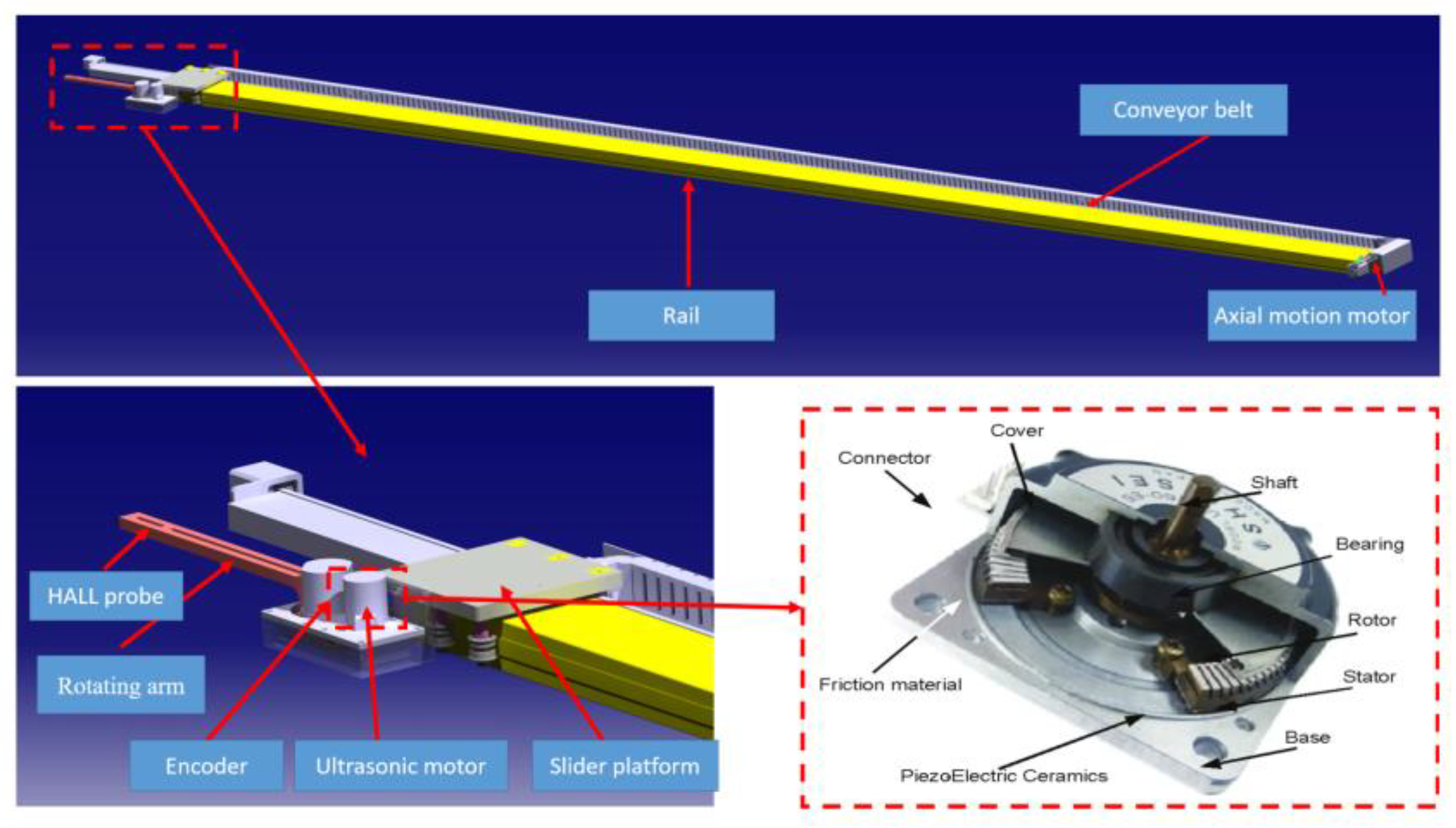
2.2. The Components of the Portable Magnetic Field Mapping Measurement System
- (1)
- The rail with a translational stroke of 4300mm when testing the HFRS warm-ion superconducting magnets, and lengthened to 5300mm when testing the HFRS anti-irradiation magnets.
- (2)
- The slider platform on which the ultrasonic motor, the encoder, and the replaceable rotating arm are placed.
- (3)
- The ultrasonic motor and the encoder have stable operation under a strong magnetic field (< 7T).
- (4)
- The rotating arm, has an initial length of 280mm, for mounting the Hall sensor, and the length can be changed.
- (5)
- The axial motion servo motor and conveyor belt, are used to transfer the sliding platform to the magnet air gap.
- (6)
- The motion control and data acquisition system, are used to realize motion control, magnetic field and current acquisition.
- (7)
- Group 3's DTM151 Gauss meter and MPT141 Hall probe.
- (8)
- Nuclear magnetic resonance instrument (NMR), used to check the magnetic field of the Gauss meter before the formal test, to ensure the accuracy of the Gauss meter itself and the fixed.
2.3. The Magnetic Field Measurement Method and Coordinate Calculation
3. Results
3.1. The Magnet Parameters and Measurement Requirements for SRing and HFRS Dipole Magnets
3.2. The Measurement of SRing Dipole Magnets
3.2.1. System Debugging
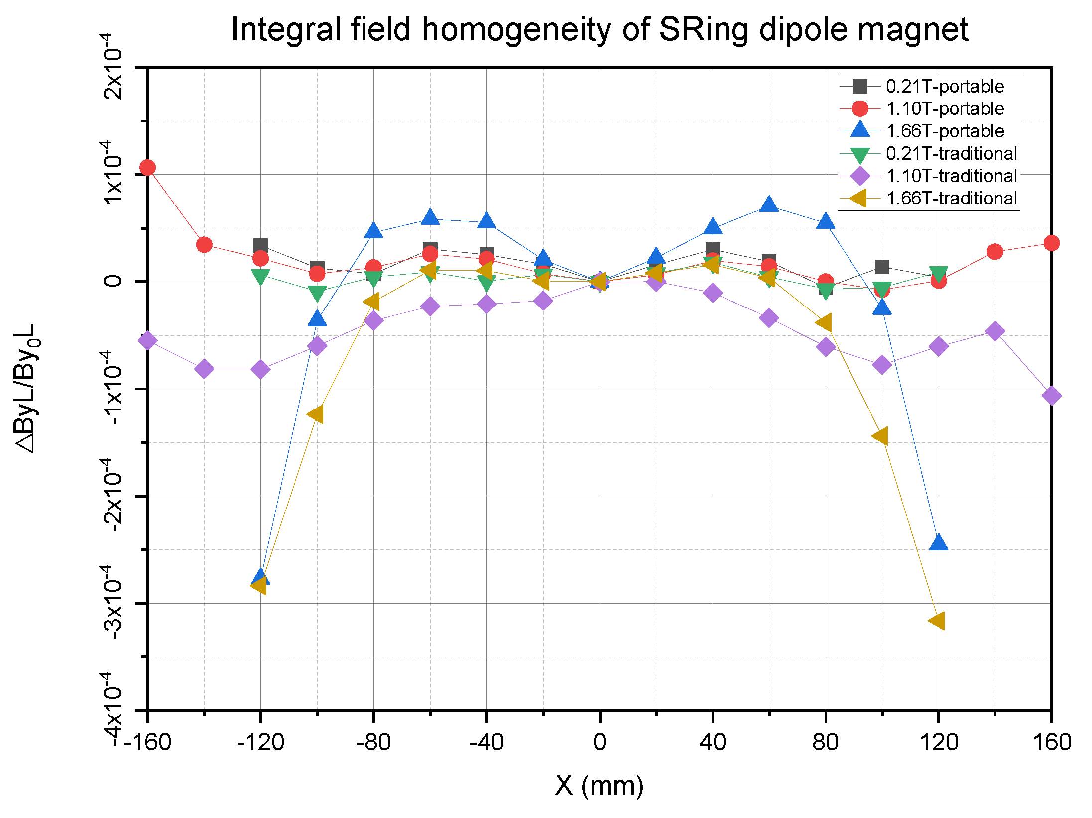
3.2.2. The Comparison between the Traditional Hall Probe Magnetic Field Mapping Measuring System and the Portable Magnetic Field Mapping Measuring System to Measure SRing Dipole Magnet
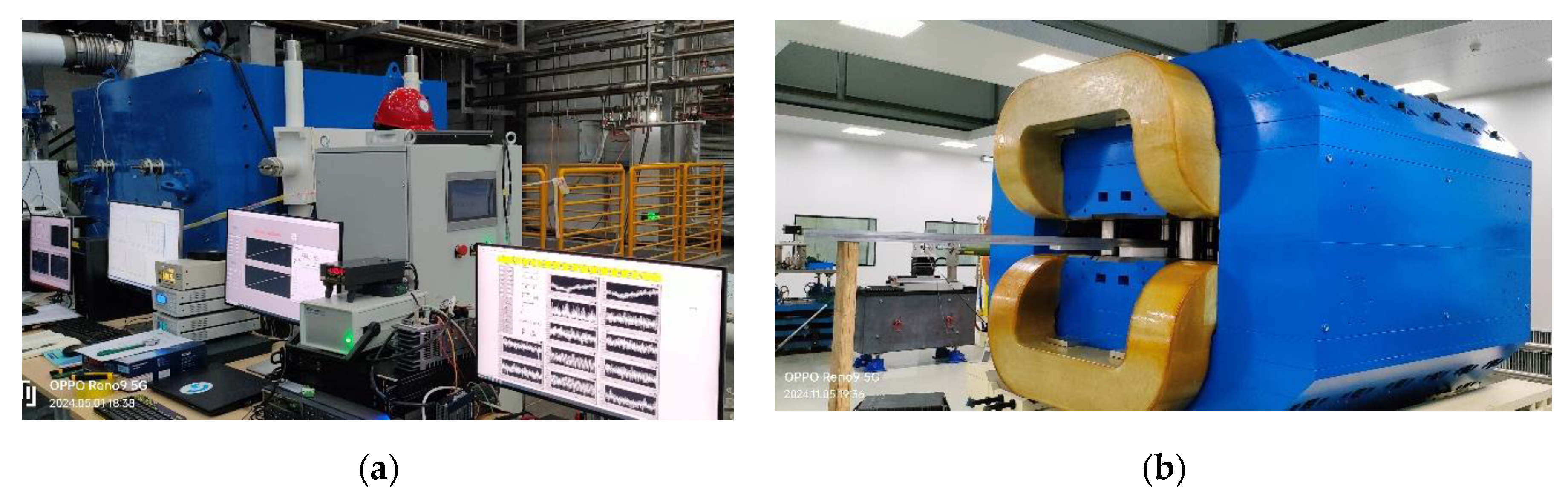
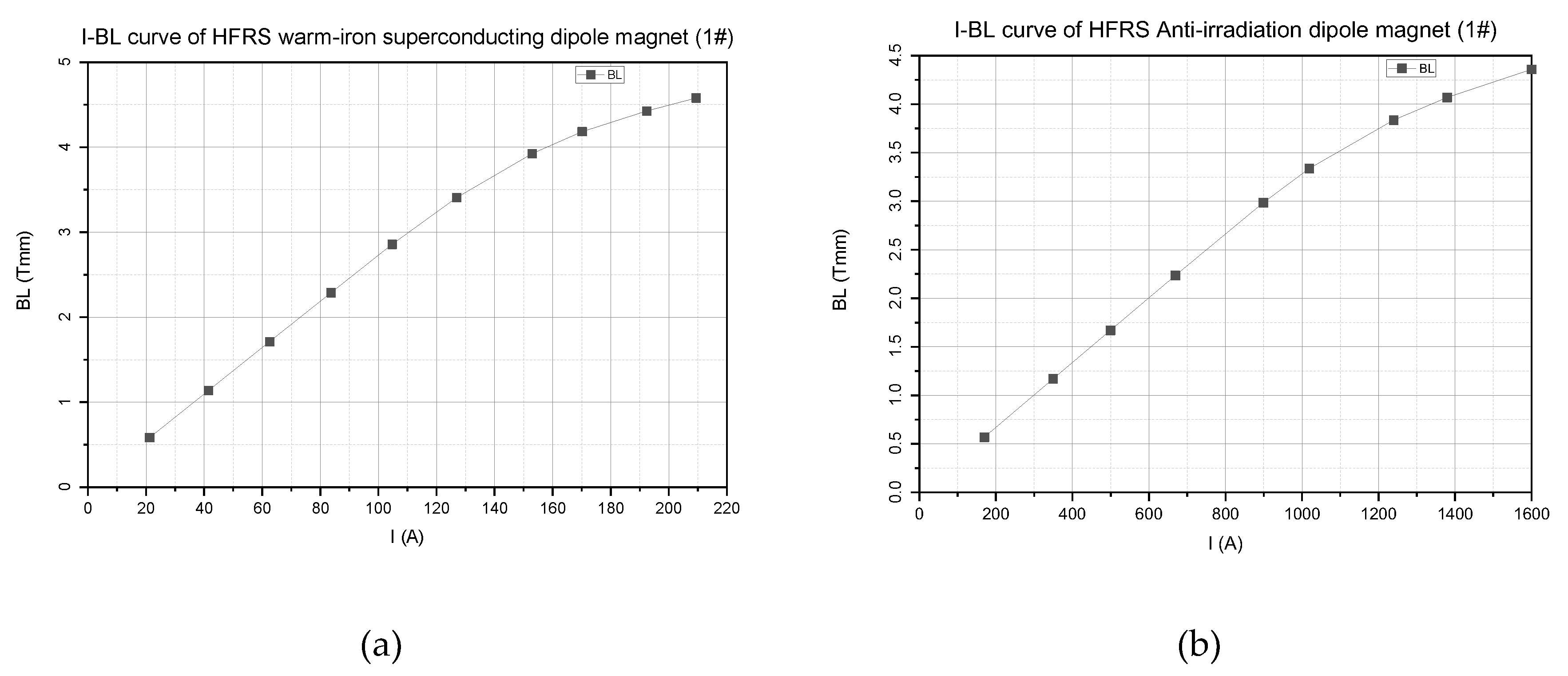
3.3. The Magnetic Field Batch Measurement of the HFRS Warm-Iron Superconducting Dipole Magnets and the HFRS Anti-Irradiation Dipole Magnets
4. Discussion
5. Conclusions
Author Contributions
Funding
Data Availability Statement
Acknowledgements
Conflicts of Interest
References
- X. Zhang, L.M. Ma, Optimization design and test of the Booster Ring dipole magnet in HIAF. Jinst, 2022; 17, P03024.
- J.C. Yang*, J.W. Xia. High Intensity heavy ion Accelerator Facility (HIAF) in China. NIMB. 2013; 317, 263–265.
- Ma X, Wen W Q. HIAF: New opportunities for atomic physics with highly charged heavy ions. NIMB. 2017; 408, 169–173.
- Xiaohong Zhou*, Jiancheng Yang. Status of the high-intensity heavy-ion accelerator facility in China. AAPPS Bull. 2022; 32, 35.
- B. Wu, J.C. Yang. The design of the Spectrometer Ring at the HIAF. NIMA. 2017; 881, 27–35.
- Sheng L N, Zhang X H. Ion-optical design of High energy Fragment Separator (HFRS) at HIAF. NIMB. 2020; 469, 1–9.
- Beimin Wu, Wei You. Mechanical Design, Construction and Testing of the Superferric Dipoles for the High Energy Fragment Separator of the HIAF. IEEE. 2024; 34, 5.
- G. Moritz. MECHANICAL EQUIPMENT. CERN ACCELERATOR SCHOOL, Europa Palapa Hotel, Anacapri, Italy, 11-17 April 1997, 251-257.
- He Yuan. Magnetic Measurement System for CSR and Its Applications. Doctor of Philosophy, University of Chinese Academy of Sciences, Beijing, June 2003.
- Lucas Samaille, Gaël Le Bec, Reine Versteegen. Update of the magnetic measurement benches of the ESRF. The 23rd International Magnetic Measurement Workshop, Bad Zurzach, Switzerland, 6–11 October 2024.
- ZHANG Xiang, JIN Li’an. Magnetic Field Measurement System of the BRing Fast Ramping Dipole Magnet in HIAF. NPR. 2022, 39, 470–475.
- G. Golluccio, M. Buzio. Instruments and methods for the magnetic measurement of the super-FRS magnets. Proceedings of IPAC2016, Busan, Korea. May 8–13 2016.
- Jan Henry Hetzel, J¨urgen B¨oker. Development of a Field Mapper for the Determination of the Multipole Components of the Curved HESR Dipole Magnets. IEEE. 2018; 28, 1–4.
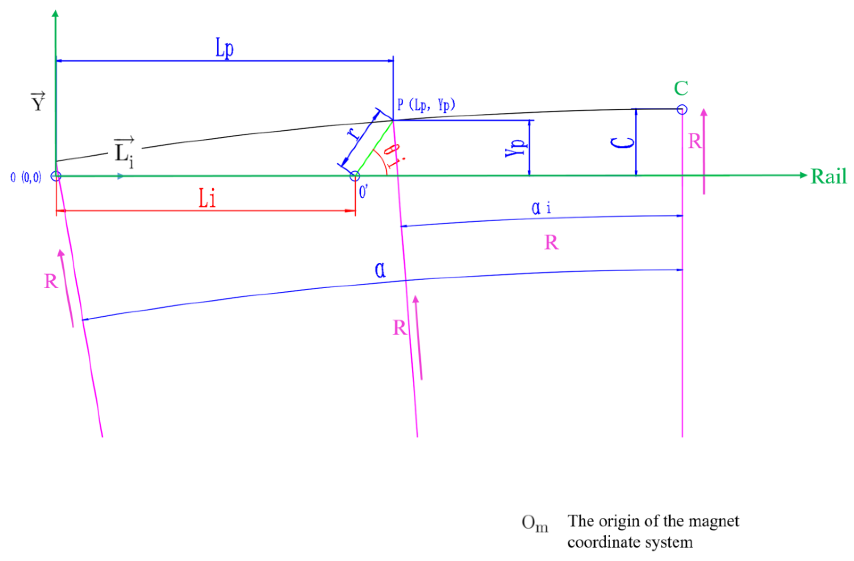


| Parameters | description |
|---|---|
| R | The radius of the dipole magnet |
| r | The radius of the rotating arm |
| linear motion variable | |
| rotational angle variable | |
| Parameters | SRing dipole magnets | HFRS warm-ion superconducting dipole magnets | HFRS anti-irradiation dipole magnets | unit |
|---|---|---|---|---|
| Number | 20 | 11 | 3 | / |
| Range of magnetic field | 0.21-1.66 | 0.22-1.6 | 0.21-1.6 | T |
| Reference magnetic field | 1.1 | 0.83 | 0.83 | T |
| Gap | ±52 | ±70 | ±103 | mm |
| Good field region (H×V) | 318×80 (0.84-1.39T) 236×80 (0.21-1.66T) |
±160×±62 | ±160×±90 | mm |
| Bending radius | 9.5 | 15.7 | 15.7 | m |
| Deflection angle | 18 | 10 | 10 | ° |
| Edge angle | 0 | 0 | 0 | ° |
| Integral field homogeneity | ±3×10⁻⁴ (318×80@1.10T) ±5×10⁻⁴ (220×80@1.66T) ±3×10⁻⁴ (240×80@0.21T) |
±3×10⁻⁴ (0.2~1.2T) | ±3×10⁻⁴ (0.83T) ±8×10⁻⁴ (1.60T) |
/ |
| Maximum current | 1780 | 210 | 1600 | A |
| weight | 45000 | 52000 | 81000 | kg |
| Items | SRing dipole magnets | HFRS warm-ion superconducting dipole magnets | HFRS anti-irradiation dipole magnets |
|---|---|---|---|
| Number | 1 | 11 | 3 |
| I-BL curve | Imax=1780 A | Imax=210 A | Imax=1600 |
| Magnetic field distribution | 0.21T, 1.1T, 1.66T | 0.22T, 0.83T, 1.6T | 0.21T, 0.83T, 1.6T |
Disclaimer/Publisher’s Note: The statements, opinions and data contained in all publications are solely those of the individual author(s) and contributor(s) and not of MDPI and/or the editor(s). MDPI and/or the editor(s) disclaim responsibility for any injury to people or property resulting from any ideas, methods, instructions or products referred to in the content. |
© 2024 by the authors. Licensee MDPI, Basel, Switzerland. This article is an open access article distributed under the terms and conditions of the Creative Commons Attribution (CC BY) license (http://creativecommons.org/licenses/by/4.0/).


