
Submitted:
18 December 2024
Posted:
19 December 2024
You are already at the latest version
Abstract
Perovskite solar cells (PSCs) have emerged as a promising photovoltaic technology, yet their stability under environmental stressors remains a critical challenge. This study examines the substrate-dependent degradation mechanisms of perovskite films and evaluates the role of me-thylammonium chloride (MACl) incorporation. Devices fabricated on ITO and glass substrates exhibited markedly different stability behaviors under high-humidity conditions. ITO substrates delayed the phase transition from the black α-phase to the yellow δ-phase due to stronger sub-strate-film interactions and reduced defect densities, while glass substrates facilitated rapid deg-radation through moisture infiltration and grain boundary instability. MACl incorporation en-hanced the initial crystallinity and optoelectronic properties of the perovskite films, as evidenced by superior power conversion efficiency and photon absorption. However, residual MACl under humid conditions introduced structural instability, particularly on glass substrates. To address these challenges, a fully coated ITO structure, referred to as the Island Type design, was proposed. This structure eliminates exposed glass regions, leveraging the stabilizing properties of ITO to suppress moisture infiltration and prolong device durability. The findings provide a compre-hensive understanding of the interplay between substrate properties and material composition in PSC stability and highlight the potential of structural optimizations to balance efficiency and durability for commercial applications.
Keywords:
Perovskite solar cells
; Methylammonium chloride (MACl)
; ITO-coated substrates
; Humidity stability
; Interlayer Interactions
; Photovoltaic device durability
1. Introduction
Perovskite solar cells (PSCs) have emerged as a transformative technology in next-generation photovoltaics, achieving power conversion efficiencies (PCEs) exceeding 25%, comparable to traditional silicon-based solar cells [1,2]. Their appeal lies in their exceptional optoelectronic properties, such as high absorption coefficients, long charge carrier diffusion lengths, and defect tolerance, which have enabled rapid advancements in efficiency [3]. Despite these advantages, the commercial adoption of PSCs is hindered by their intrinsic instability under environmental stressors, including moisture, oxygen, and thermal fluctuations, which lead to phase degradation and shorter operational lifetimes [4,5]. These environmental sensitivities present significant challenges that must be addressed for PSCs to transition from research to real-world applications [6,7].
To address the stability challenges of PSCs, various strategies have been developed, with one promising approach being the incorporation of additives into perovskite precursor solutions [8,9]. Additives play a crucial role in enhancing crystallinity, optimizing grain growth, and reducing surface defects, thereby improving film quality and structural stability [8,9]. Among these, methylammonium chloride (MACl) has emerged as a particularly effective additive, known for promoting larger grain sizes and better crystallinity in perovskite films. In conventional PSC fabrication, MACl is expected to volatilize during high-temperature annealing, leaving minimal residue in the perovskite layer. However, under low-temperature annealing conditions, our study observed that residual MACl remains trapped within the perovskite layer, potentially interacting with other device components [10]. This finding highlights the dualistic role of MACl: while it enhances initial crystallization and device performance, the persistence of residual MACl can create degradation pathways, particularly under environmental stress [10,11]. These observations call for a deeper understanding of the balance between MACl’s benefits and its potential drawbacks in PSC fabrication [12,13].
In addition to additives, interlayers have become essential for stabilizing PSCs by enhancing charge transport and reducing recombination [14,15,16]. The commonly employed n-i-p structure in PSCs positions the perovskite layer between an electron transport layer (ETL) and a hole transport layer (HTL), forming an efficient pathway for charge extraction [17]. Recently, cyclohexylmethylammonium iodide (CHMAI) has attracted significant attention as an interlayer material positioned between the perovskite and HTL [18]. CHMAI has been shown to effectively facilitate charge extraction, reduce recombination losses, and improve overall device efficiency [18,19,20]. Interlayers such as CHMAI are crucial for achieving high PCEs, as they passivate surface defects on the perovskite, improve film morphology, and enhance device durability [15,18,21]. Initially, phenethylamine-based interlayers were widely adopted in PSCs, but recent studies suggest that replacing the phenyl group with a hexyl group, as in CHMAI, leads to superior stability and efficiency [18,22]. This advancement demonstrates the critical role of interlayer composition in optimizing PSC performance and demonstrates the potential of tailored interlayers to address both efficiency and stability challenges [16,22].
While previous studies have extensively explored the influence of substrate layers on the quality and stability of perovskite films, the interaction between substrate type and interlayer materials remains underexplored. Existing literature highlights how different underlying substrates can affect the crystallinity, defect density, and overall film morphology of perovskite layers [23]. However, the consequential effects of substrate choice on the chemical and physical interactions between perovskite and interlayers, such as CHMAI, have not been thoroughly investigated. Our research distinguishes itself by systematically examining how varying substrate materials not only influence the intrinsic properties of perovskite films but also modulate the interactions with interlayer components. This dual focus provides a more comprehensive understanding of PSC architecture, revealing that substrate type can significantly alter the efficacy of interlayers in enhancing device performance and stability. By exploring these complex interactions, our study fills a critical gap in the current body of knowledge and offers insights for the design of more robust and efficient PSCs.
Despite the general expectation that interlayers enhance perovskite stability, our study reveals a complex interaction between residual MACl and the interlayer material CHMAI [24,25]. Specifically, residual MACl was found to accelerate the degradation of the perovskite layer in the presence of CHMAI, driving a rapid phase transition from the black α-phase to the yellow δ-phase [5]. Under typical conditions, interlayers are understood to stabilize perovskite films by passivating surface defects and improving the crystalline structure [15,16]. However, our findings suggest that residual MACl disrupts this stabilizing effect, triggering detrimental interactions that compromise both the structural and optoelectronic properties of the film [24,26]. This unexpected behavior challenges the conventional role of interlayers as stabilizing agents in PSCs and highlights the dualistic nature of MACl [25,27]. While MACl promotes crystallization and grain growth, its residual presence under specific interlayer conditions can introduce significant instability [5,26].
Herein, we specifically investigated how the choice between etched and non-etched indium tin oxide (ITO) substrates affects degradation behavior in perovskite films, particularly in the presence of residual MACl. Etched ITO substrates feature both bare glass and ITO-covered regions, creating distinct surface environments for the perovskite layer. When PSCs were fabricated on etched ITO, we found that perovskite films degrade more rapidly on bare glass regions compared to ITO-covered regions. This degradation pattern suggests that the ITO layer may inhibit degradation by reducing the reactivity of residual MACl, thereby slowing down degradation processes. This observation has important implications for device performance, as degradation across the interface between yellow-phase perovskite on bare glass and black-phase perovskite on ITO can create imperfect boundaries. These boundaries may lead to shunt pathways, which disrupt the device's electrical stability and reduce efficiency. In contrast, non-etched ITO substrates allow the black phase to persist more uniformly, even under conditions that typically accelerate degradation, indicating that substrate choice is critical for both chemical and mechanical stability in PSCs.
To evaluate these findings in greater detail, we systematically compared the current-voltage characteristics and long-term stability of PSCs fabricated on non-etched and etched ITO substrates, specifically when using MACl-containing precursors and CHMAI interlayers. Our results demonstrate that non-etched ITO substrates result in higher efficiency and improved stability, suggesting that continuous ITO layers are more effective at maintaining the integrity of the perovskite layer.
2. Materials and Methods
2.1. Reagents Information
Perovskite precursor solutions were prepared using formamidinium iodide (FAI, >99.0%, Greatcell Solar Materials), lead(II) iodide (PbI₂, >98.0%, TCI Chemicals), cesium bromide (CsBr, >99.9%, TCI Chemicals), and methylammonium chloride (MACl, ≥99.0%, TCI Chemicals). Dimethylformamide (DMF, ≥99.8%, Sigma-Aldrich) and dimethyl sulfoxide (DMSO, ≥99.9%, Alfa Aesar) were used as solvents for the perovskite solution. Cyclohexylmethylammonium iodide (CHMAI, ≥99.0%, Greatcell Solar Materials) dissolved in isopropanol (IPA, ≥99.5%, Sigma-Aldrich) was employed as an interlayer material. Spiro-OMeTAD (Lumtec) was doped with lithium bis(trifluoromethanesulfonyl)imide (Li-TFSI, ≥99.9%, Lumtec) and 4-tert-butylpyridine (tBP, ≥96.0%, TCI Chemicals) to prepare the hole transport layer solution. Chlorobenzene (CB, ≥99.5%, Sigma-Aldrich) was used as the solvent for Spiro-OMeTAD.
2.2. Preparation of Solution
The perovskite precursor solution, with a composition of (FA0.97Cs0.03)Pb(I0.99Br0.01)3, was prepared at a total concentration of 1.35 M by dissolving 6.03 mg of cesium bromide (CsBr), 157.64 mg of formamidinium iodide (FAI), 435.65 mg of lead(II) iodide (PbI₂), and 15.95 mg of methylammonium chloride (MACl) in a mixture of 630 µL of dimethylformamide (DMF) and 70 µL of N-methyl-2-pyrrolidone (NMP) in a 9:1 volume ratio. Depending on the experimental conditions, the solution was prepared with or without MACl. The precursor solutions were mixed using a vortex mixer to ensure thorough blending of all components.
A SnO₂ solution was prepared by mixing 375 µL of SnO₂ nanoparticles with 1125 µL of deionized water, maintaining a 1:3 ratio.
The hole transport layer (HTL) was prepared by first dissolving 50.61 mg of Spiro-OMeTAD in 700 µL of chlorobenzene using a vortex mixer to ensure complete dissolution. Subsequently, 18.62 µL of lithium bis(trifluoromethanesulfonyl)imide (Li-TFSI) and 20.16 µL of 4-tert-butylpyridine (tBP) were doped into the Spiro-OMeTAD solution.
The interlayer was prepared by first dissolving 12 mg of cyclohexylmethylammonium iodide (CHMAI) in 2 mL of isopropanol (IPA) using a vortex mixer to ensure complete dissolution.
2.3. Device Fabrication
ITO-coated glass substrates with etched regions were cleaned through sequential ultrasonication in deionized water, acetone, and isopropanol, each for 15 minutes. The substrates were then treated with UV-ozone for 15 minutes to enhance surface wettability. The SnO₂ solution, as prepared in Section 2.2, was statically dispensed onto the substrates at 100 µL and spin-coated at 5000 rpm for 30 seconds. To ensure proper adhesion and stabilize the film, the SnO₂ layer was subsequently annealed at 150°C for at least 15 minutes, a step crucial for the complete evaporation of deionized water. Following annealing, the substrates were subjected to an additional UV-ozone treatment for 10 minutes.
The perovskite precursor solution, with a composition of (FA0.97Cs0.03)Pb(I0.99Br0.01)3, was prepared at a total concentration of 1.35 M by dissolving 6.03 mg of cesium bromide (CsBr), 157.64 mg of formamidinium iodide (FAI), 435.65 mg of lead(II) iodide (PbI₂), and 15.95 mg of methylammonium chloride (MACl) in a mixture of 630 µL of dimethylformamide (DMF) and 70 µL of N-methyl-2-pyrrolidone (NMP). Depending on the experimental conditions, the solution was prepared with or without MACl. The precursor solutions were mixed using a vortex mixer to ensure thorough blending of all components.
For perovskite film spin-coating, 50 µL of the precursor solution was statically dispensed onto the SnO₂-coated substrates, which had undergone UV-ozone treatment. The spin-coating process was performed at 3000 rpm for 30 seconds. During spin-coating, 30 µL of chlorobenzene was dropped onto the rotating substrate at 12–15 seconds to induce anti-solvent crystallization. The coated films were then annealed at 100°C for 1 hour to form the perovskite layer.
An interlayer of CHMAI was spin-coated on top of the perovskite layer by statically dispensing 40 µL of a CHMAI solution in isopropanol onto the substrate once the spin coater reached 5000 rpm, maintaining the spin-coating process for 30 seconds. No additional annealing step was performed after the coating.
The hole transport layer (HTL) was statically dispensed onto the CHMAI-coated perovskite films when the spin coater reached 2500 rpm, and the spin-coating process was maintained for 30 seconds to complete the HTL layer.
Finally, gold electrodes were deposited on top of the HTL using a thermal evaporator under high vacuum (<3.0×10⁻⁶ Torr) with a patterned metal mask.
2.4. Measurement Condition
The current density-voltage (J-V) characteristics were measured under 1 sun equivalent illumination using an Ossila Solar Cell I-V Test system. X-ray diffraction (XRD) analysis was conducted with a Rigaku SmartLab instrument, employing Cu Kα radiation and recording data at 0.02° intervals. Photoluminescence (PL) and time-resolved photoluminescence (TRPL) measurements were performed using a time-correlated single-photon counting (TCSPC) system (FLS1000, Edinburgh Instruments) with a pulsed laser source at 450 nm. Scanning electron microscopy (SEM) images, both cross-sectional and planar, were captured with a Hitachi SU8600, while atomic force microscopy (AFM) data were obtained using an MFP-3D Origin+ system (Oxford Instruments). XRD, PL, SEM, and AFM analyses were performed at the Central Laboratory of Hankyong National University on samples prepared using ITO-coated substrates. The substrates were etched and sequentially coated with SnO₂, perovskite, and CHMAI.
3. Results and Discussion
The investigation began with the fabrication of devices utilizing the etched ITO structure depicted in Figure 1(a). This design allowed a direct comparison of perovskite film stability between ITO-covered and glass-exposed regions, creating distinct chemical and physical environments. Two types of devices were fabricated for comparison: MACl_X, where no MACl was added to the perovskite precursor solution, and MACl_O, where MACl was included. This distinction was crucial for evaluating the impact of residual MACl on the long-term stability of the perovskite films.
During experiments conducted under a relative humidity exceeding 40%, a striking visual difference was observed over time, as shown in Figure 1(b). On Day 1, there was no significant visual difference between the MACl_O condition on ITO and glass substrates. The perovskite films on the ITO-covered regions retained the black α-phase, associated with the photoactive state, even after several days. However, as time progressed, distinct differences emerged; by Day 5 and Day 8, the films on the glass-exposed regions rapidly transitioned to the yellow δ-phase, a non-photoactive state indicative of structural degradation. In contrast, films on the glass-exposed regions rapidly transitioned to the yellow δ-phase, a non-photoactive state indicative of structural degradation. These visual changes were absent when the relative humidity was maintained below 30%, indicating that moisture infiltration plays a critical role in the degradation process. Furthermore, the transition to the δ-phase was more significant in MACl_O devices, suggesting that the presence of residual MACl exacerbates degradation.
The normalized performance data in Figure 1(c) supports these observations. Under the MACl_O condition, device performance declined rapidly, whereas devices under the MACl_X condition maintained stable performance over time with minimal changes in efficiency. This suggests that residual MACl contributes to performance degradation. Furthermore, these results emphasize the critical role of the ITO surface in reducing moisture-induced degradation.
To further investigate the substrate-dependent degradation behavior observed in Figure 1, XRD analysis was conducted. The results, presented in Figure 2(a), reveal a characteristic phase transformation from the black α-phase to the yellow δ-phase in perovskite films under the MACl_O condition. On Day 1, all conditions exhibited a prominent α-phase peak near 14.1°, corresponding to the (110) plane of the black-phase perovskite. However, in the MACl_O condition, the intensity of the α-phase peak gradually decreased over time, accompanied by the emergence of the δ-phase peak near 11.9°, corresponding to the (100) plane of the yellow-phase perovskite.
In contrast, the MACl_X condition exhibited a distinct 2D perovskite (CHMA₂PbI₄) (002) plane peak near 5.2° from Day 1. This peak showed consistently higher intensity compared to the MACl_O condition, indicating that the 2D perovskite structure was more prominent under the MACl_X condition. While the MACl_O condition also displayed the same 2D perovskite peak near 5.2°, its lower intensity suggests a difference in the degree of 2D phase formation between the two conditions.
To quantitatively evaluate this phase transformation, the intensity ratio () was defined as follows:
Where is the intensity of the δ-phase peak at 11.9° and is the intensity of the α-phase peak at 14.1°. This metric provides a reliable means of tracking phase stability and comparing the degradation rates between different substrates.
As shown in Figure 2(b), the increased more rapidly for perovskite films on glass substrates than on ITO substrates. This observation demonstrates that the transition from the α-phase to the δ-phase occurs significantly faster on glass substrates, highlighting their greater susceptibility to structural degradation. In contrast, perovskite films on ITO substrates exhibited a much slower increase in , indicating their enhanced ability to stabilize the α-phase and delay the phase transformation, even under high-humidity conditions. The actual intensity changes of the δ-phase (11.9°) and α-phase (14.1°) peaks for glass and ITO substrates under the MACl_O condition are shown in Figure S1, providing additional insight into this phase transformation.
PL and TRPL measurements were conducted to investigate substrate-dependent differences in perovskite film quality and stability.
The PL spectra in Figure 3(a) show a pronounced quenching effect in the MACl_X condition. Films on ITO substrates exhibited lower PL intensity compared to those on glass, indicating more efficient charge extraction at the ITO interface. The stronger interactions between the ITO substrate and the perovskite layer facilitate charge transport and reduce radiative recombination. In contrast, the higher PL intensity observed on glass substrates reflects weaker substrate-film interactions, which hinder charge extraction and lead to increased radiative recombination. These results highlight the significant role of substrate properties in determining charge transport efficiency.
In the MACl_O condition, the difference in PL intensity between ITO and glass substrates was significantly reduced. This trend indicates that perovskite films on glass undergo severe structural and electronic degradation in the presence of MACl. Residual MACl results in increased non-radiative recombination and reduced optoelectronic performance. In contrast, perovskite films on ITO substrates showed relatively better stability, demonstrating the stabilizing effect of the ITO surface even under conditions involving residual MACl.
Time-resolved photoluminescence (TRPL) measurements, shown in Figure 3(b) and Figure 3(c), provide further insight into charge carrier dynamics under different conditions. Under the MACl_X condition, as showned in Figure 3(b), films on ITO substrates exhibited faster decay rates, indicating efficient charge quenching and shorter carrier lifetimes. Conversely, films on glass substrates showed slower decay rates, consistent with higher defect densities and less efficient charge extraction. These observations align with the PL findings, underscoring the superior charge transport properties of the ITO substrate.
Under the MACl_O condition, as shown in Figure 3(c), the carrier lifetimes for both ITO and glass substrates were significantly reduced, with minimal differences observed between the two. This suggests that residual MACl negatively affects the structural quality and charge transport dynamics of the perovskite films on both substrates. Residual MACl promotes non-radiative recombination and reducing carrier mobility. This effect is particularly detrimental on glass substrates, where weaker film-substrate interactions exacerbate the degradation.
To investigate substrate-dependent differences in surface structure and degradation, SEM analyses were performed. The SEM images, shown in Figure 4(a),(b), illustrate the surface morphology of perovskite films on ITO and glass substrates on Day 1. At this stage, both substrates exhibited uniform grain distribution and well-defined grain boundaries, with no significant differences observed in geometry.
By Day 8, as depicted in Figure 4(c),(d), morphological changes were observed over time, likely resulting from the transformation of the α-phase to the δ-phase. However, SEM analysis revealed no substantial geometric differences between the ITO and glass substrates, indicating that the phase transition did not significantly alter the overall surface structure of either substrate.
AFM measurements, as presented in Figure 5(a-d) and Table 1, provide a quantitative analysis of surface roughness for perovskite films on glass and ITO substrates under the MACl_O condition. These results capture the temporal evolution of film morphology on both substrates. Figure 5(a–d) presents 3D AFM images of perovskite films, while the corresponding 2D AFM images are provided in Figure S2 of the Supporting Information for further reference.
On Day 1 ( Figure 5(a),(b)), the RMS roughness values show that perovskite films on ITO substrates exhibit a slightly higher surface roughness (39.59 nm) compared to those on glass substrates (38.55 nm), as summarized in Table 1. This difference arises from the inherently rougher morphology of the ITO surface, which influences the initial film formation.
By Day 8 ( Figure 5(c),(d)), the trend reverses, with the RMS roughness of glass substrates increasing sharply to 41.99 nm, while that of ITO substrates decreases to 33.35 nm. This result indicates that the initially smoother glass substrates experience significant surface degradation over time, likely driven by external environmental factors. In contrast, the ITO substrates exhibit improved surface smoothness, suggesting greater resistance to roughness evolution.
To better explain the degradation mechanism, a schematic representation of moisture infiltration is provided in Figure 5(e). This schematic illustrates how the smoother glass substrate promotes deeper moisture penetration through grain boundary gaps, leading to localized degradation and destabilization [25]. In contrast, the initially rougher ITO substrate reduces grain boundary voids, resulting in a denser perovskite layer that limits pathways for moisture ingress. This may make ITO substrates relatively more stable compared to glass, which contains more voids that facilitate moisture infiltration. Additionally, the hydrophilic nature of CHMAI and its interaction with residual moisture and unreacted MACl likely accelerate water penetration into the perovskite layer.
The J-V characteristics shown in Figure 6(a) and summarized in Table 2 reveal that devices fabricated under the MACl_O condition achieved higher initial power conversion efficiencies (PCE) compared to those fabricated under the MACl_X condition. Specifically, the reverse scan PCE of MACl_O devices reached 21.51%, surpassing the 17.99% observed for MACl_X devices. This enhanced performance in MACl_O devices can be attributed to the role of MACl in promoting larger grain sizes, improved crystallinity, and reduced defect densities during perovskite film formation.
To quantify the extent of charge recombination, the hysteresis index (HI) was calculated using the following equation:
where PCEreverse and PCEforward represent the power conversion efficiencies measured in reverse and forward scans, respectively. Higher HI values indicate greater discrepancies between the two scan directions, reflecting increased charge recombination and interfacial instabilities. However, the HI values for MACl_O devices (0.03) and MACl_X devices (0.04) showed no significant difference.
In contrast, devices fabricated under the MACl_X condition demonstrated lower initial PCE values, with a reverse scan efficiency of 17.99% as shown in Table 2. However, these devices exhibited significantly greater stability over time. In the MACl_X condition, the absence of residual MACl reduced the moisture-induced degradation pathway observed in MACl_O devices, specifically the formation of the δ-phase. The reduced hysteresis index (HI) in MACl_X devices further supports their superior long-term performance, as it indicates more stable charge transport and reduced interfacial instabilities. These findings highlight the dual role of MACl in perovskite solar cells, where its ability to enhance crystallization and optoelectronic performance must be carefully balanced against its detrimental impact on stability.
The EQE spectra presented in Figure 6(b) further validate the trends observed in the I-V measurements. Devices under the MACl_O condition consistently exhibited higher external quantum efficiency (EQE) across the 400–800 nm wavelength range compared to MACl_X devices. This superior EQE performance highlights the enhanced photon absorption and charge collection efficiency achieved through MACl incorporation.
To address the stability challenges observed in MACl_O devices, a structural optimization is proposed, as shown in Figure 6(c),(d). This design, referred to as the "Island Type" structure, eliminates the exposed glass regions identified as primary sites of moisture infiltration and degradation. As shown in Figure 6(c), for devices without MACl incorporation (MACl_X), both the etched type and Island Type structures exhibited good stability over time, as indicated by the minimal decrease in normalized PCE. However, for devices with MACl incorporation (MACl_O), the Island Type structure demonstrated significantly better stability compared to the etched type, which showed a rapid decline in performance. By employing a fully coated ITO layer, the Island Type structure leverages the stabilizing properties of ITO substrates, including their rough surface morphology and strong interfacial interactions. This continuous ITO layer minimizes grain boundary gaps, reduces pathways for moisture ingress, and enhances the structural integrity of the perovskite layer. Such an optimized design offers a practical solution to balance the high efficiency provided by MACl incorporation with the need for long-term stability in perovskite solar cells.
The Island Type structure is beneficial because it fully coats the ITO layer, leveraging its superior moisture resistance and strong interfacial interactions to enhance device stability. This design minimizes the exposure of moisture-prone regions, such as glass, and addresses the vulnerabilities of conventional structures, offering a balanced approach to improving both efficiency and long-term durability in perovskite solar cells.
4. Conclusions
This study investigated the effects of MACl incorporation, substrate selection, and device architecture on the performance and stability of perovskite solar cells. While MACl improved initial crystallinity and efficiency by increasing grain sizes and reducing defect densities, its residual presence under humid conditions caused significant stability issues, especially on smoother glass substrates. In contrast, ITO substrates offered better stability due to their rougher surface and stronger interfacial interactions, which reduced moisture infiltration and structural degradation.
The Island Type structure addresses these challenges by eliminating vulnerable glass-exposed regions and leveraging the stabilizing properties of ITO, achieving a balance between efficiency and durability. These findings emphasize the importance of combining material optimization and structural engineering to create stable, high-performance perovskite solar cells, while pointing to future work on refining interlayer materials, scalable fabrication, and real-world testing.
Supplementary Materials
The following supporting information can be downloaded at the website of this paper posted on Preprints.org. Figure S1: Intensity changes of the perovskite δ-phase peak at 11.9° (a) and α-phase peak at 14.1° (b) over time on glass and ITO substrates under the MACl_O_100 condition. Figure S2: (a) 2D AFM images of perovskite films on glass substrates at Day 1. (b) 2D AFM images of perovskite films on ITO substrates at Day 1. (c) 2D AFM images of perovskite films on glass substrates at Day 8. (d) 2D AFM images of perovskite films on ITO substrates at Day 8.
Author Contributions
Conceptualization, M.S. and J.K and G.M.K.; formal analysis, M.S. and J.K and G.M.K.; writing—original draft preparation, M.S.; writing—review and editing, G.M.K.; supervision, G.M.K.; All authors have read and agreed to the published version of the manuscript.
Funding
This study was supported by the National Research Foundation of Korea (NRF) grant funded by the Korean Government (MSIT) (Grant No. 2021R1G1A10123621312582071420103).
Acknowledgments
We are grateful for the XRD, PL, SEM, and AFM measurements conducted at the Central Laboratory of Hankyong National University.
Conflicts of Interest
The authors declare no conflicts of interest.
References
- Green, M.A.; Dunlop, E.D.; Yoshita, M.; Kopidakis, N.; Bothe, K.; Siefer, G.; Hao, X.; Jiang, J.Y. Solar Cell Efficiency Tables (Version 65). Progress in photovoltaics: research and applications 2024.
- Correa-Baena, J.-P.; Abate, A.; Saliba, M.; Tress, W.; Jacobsson, T.J.; Grätzel, M.; Hagfeldt, A. The rapid evolution of highly efficient perovskite solar cells. Energy & Environmental Science 2017, 10, 710-727.
- Correa-Baena, J.-P.; Saliba, M.; Buonassisi, T.; Grätzel, M.; Abate, A.; Tress, W.; Hagfeldt, A. Promises and challenges of perovskite solar cells. Science 2017, 358, 739-744.
- Saliba, M.; Correa-Baena, J.P.; Grätzel, M.; Hagfeldt, A.; Abate, A. Perovskite solar cells: from the atomic level to film quality and device performance. Angewandte Chemie International Edition 2018, 57, 2554-2569.
- Mazumdar, S.; Zhao, Y.; Zhang, X. Stability of perovskite solar cells: Degradation mechanisms and remedies. Frontiers in Electronics 2021, 2, 712785.
- Snaith, H.J. Present status and future prospects of perovskite photovoltaics. Nature materials 2018, 17, 372-376.
- Park, N.-G.; Grätzel, M.; Miyasaka, T.; Zhu, K.; Emery, K. Towards stable and commercially available perovskite solar cells. Nature Energy 2016, 1, 1-8.
- Jeon, N.J.; Noh, J.H.; Kim, Y.C.; Yang, W.S.; Ryu, S.; Seok, S.I. Solvent engineering for high-performance inorganic–organic hybrid perovskite solar cells. Nature materials 2014, 13, 897-903.
- Xiao, Z.; Dong, Q.; Bi, C.; Shao, Y.; Yuan, Y.; Huang, J. Solvent annealing of perovskite-induced crystal growth for photovoltaic-device efficiency enhancement. Advanced Materials 2014, 26.
- Yang, W.S.; Noh, J.H.; Jeon, N.J.; Kim, Y.C.; Ryu, S.; Seo, J.; Seok, S.I. High-performance photovoltaic perovskite layers fabricated through intramolecular exchange. Science 2015, 348, 1234-1237.
- Bryant, D.; Aristidou, N.; Pont, S.; Sanchez-Molina, I.; Chotchunangatchaval, T.; Wheeler, S.; Durrant, J.R.; Haque, S.A. Light and oxygen induced degradation limits the operational stability of methylammonium lead triiodide perovskite solar cells. Energy & Environmental Science 2016, 9, 1655-1660.
- Turren-Cruz, S.-H.; Hagfeldt, A.; Saliba, M. Methylammonium-free, high-performance, and stable perovskite solar cells on a planar architecture. Science 2018, 362, 449-453.
- Abdi-Jalebi, M.; Andaji-Garmaroudi, Z.; Cacovich, S.; Stavrakas, C.; Philippe, B.; Richter, J.M.; Alsari, M.; Booker, E.P.; Hutter, E.M.; Pearson, A.J. Maximizing and stabilizing luminescence from halide perovskites with potassium passivation. Nature 2018, 555, 497-501.
- Jiang, Q.; Chu, Z.; Wang, P.; Yang, X.; Liu, H.; Wang, Y.; Yin, Z.; Wu, J.; Zhang, X.; You, J. Planar-structure perovskite solar cells with efficiency beyond 21%. Advanced materials 2017, 29, 1703852.
- Saliba, M.; Matsui, T.; Seo, J.-Y.; Domanski, K.; Correa-Baena, J.-P.; Nazeeruddin, M.K.; Zakeeruddin, S.M.; Tress, W.; Abate, A.; Hagfeldt, A. Cesium-containing triple cation perovskite solar cells: improved stability, reproducibility and high efficiency. Energy & environmental science 2016, 9, 1989-1997.
- Zhou, H.; Chen, Q.; Li, G.; Luo, S.; Song, T.-b.; Duan, H.-S.; Hong, Z.; You, J.; Liu, Y.; Yang, Y. Interface engineering of highly efficient perovskite solar cells. Science 2014, 345, 542-546.
- Yang, W.S.; Park, B.-W.; Jung, E.H.; Jeon, N.J.; Kim, Y.C.; Lee, D.U.; Shin, S.S.; Seo, J.; Kim, E.K.; Noh, J.H. Iodide management in formamidinium-lead-halide–based perovskite layers for efficient solar cells. Science 2017, 356, 1376-1379.
- Grancini, G.; Roldán-Carmona, C.; Zimmermann, I.; Mosconi, E.; Lee, X.; Martineau, D.; Narbey, S.; Oswald, F.; De Angelis, F.; Graetzel, M. One-Year stable perovskite solar cells by 2D/3D interface engineering. Nature communications 2017, 8, 15684.
- Hou, Y.; Chen, W.; Baran, D.; Stubhan, T.; Luechinger, N.A.; Hartmeier, B.; Richter, M.; Min, J.; Chen, S.; Quiroz, C.O.R. Overcoming the interface losses in planar heterojunction perovskite-based solar cells. Advanced Materials 2016, 28, 5112-5120.
- Saliba, M.; Correa-Baena, J.-P.; Wolff, C.M.; Stolterfoht, M.; Phung, N.; Albrecht, S.; Neher, D.; Abate, A. How to Make over 20% Efficient Perovskite Solar Cells in Regular (n–i–p) and Inverted (p–i–n) Architectures. Chemistry of Materials 2018, 30, 4193-4201.
- Jeng, J.Y.; Chiang, Y.F.; Lee, M.H.; Peng, S.R.; Guo, T.F.; Chen, P.; Wen, T.C. CH3NH3PbI3 perovskite/fullerene planar-heterojunction hybrid solar cells. Advanced materials 2013, 25, 3727-3732.
- Saliba, M.; Matsui, T.; Domanski, K.; Seo, J.-Y.; Ummadisingu, A.; Zakeeruddin, S.M.; Correa-Baena, J.-P.; Tress, W.R.; Abate, A.; Hagfeldt, A. Incorporation of rubidium cations into perovskite solar cells improves photovoltaic performance. Science 2016, 354, 206-209.
- Zhang, H.; Zhao, C.; Li, D.; Guo, H.; Liao, F.; Cao, W.; Niu, X.; Zhao, Y. Effects of substrate temperature on the crystallization process and properties of mixed-ion perovskite layers. Journal of Materials Chemistry A 2019, 7, 2804-2811.
- Zhao, Y.; Zhu, K. CH3NH3Cl-assisted one-step solution growth of CH3NH3PbI3: structure, charge-carrier dynamics, and photovoltaic properties of perovskite solar cells. The Journal of Physical Chemistry C 2014, 118, 9412-9418.
- Chen, H.; Ye, F.; Tang, W.; He, J.; Yin, M.; Wang, Y.; Xie, F.; Bi, E.; Yang, X.; Grätzel, M. A solvent-and vacuum-free route to large-area perovskite films for efficient solar modules. Nature 2017, 550, 92-95.
- Li, Z.; Xiao, C.; Yang, Y.; Harvey, S.P.; Kim, D.H.; Christians, J.A.; Yang, M.; Schulz, P.; Nanayakkara, S.U.; Jiang, C.-S. Extrinsic ion migration in perovskite solar cells. Energy & Environmental Science 2017, 10, 1234-1242.
- Zheng, X.; Hou, Y.; Bao, C.; Yin, J.; Yuan, F.; Huang, Z.; Song, K.; Liu, J.; Troughton, J.; Gasparini, N. Managing grains and interfaces via ligand anchoring enables 22.3%-efficiency inverted perovskite solar cells. Nature Energy 2020, 5, 131-140.
Figure 1.
(a) Schematic of the etched ITO device structure used in this study. (b) Visual evolution of the perovskite layer over time under the MACl_O condition. (c) Normalized performance data of MACl_X and MACl_O devices over time.
Figure 1.
(a) Schematic of the etched ITO device structure used in this study. (b) Visual evolution of the perovskite layer over time under the MACl_O condition. (c) Normalized performance data of MACl_X and MACl_O devices over time.
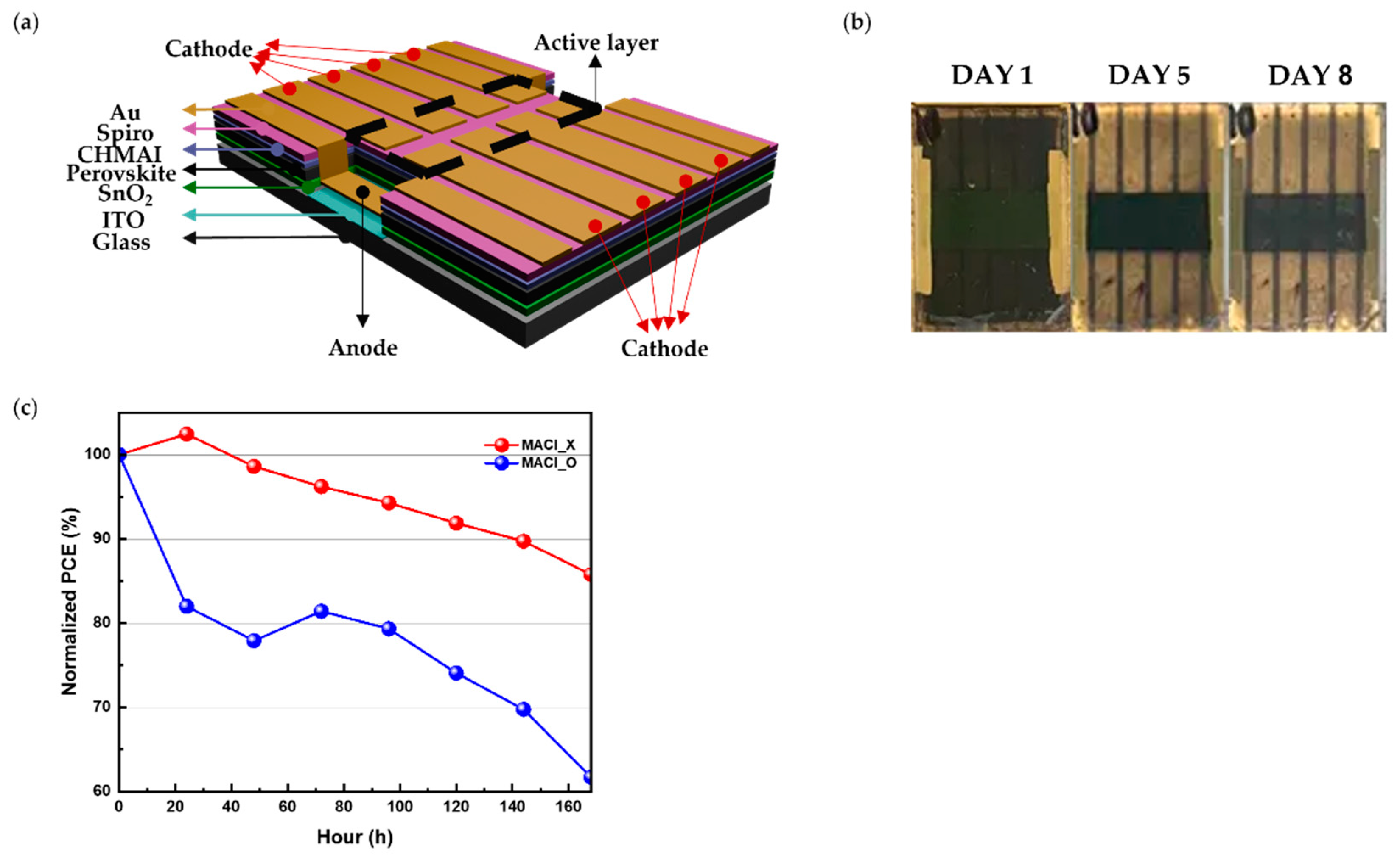
Figure 2.
(a) XRD patterns of perovskite films for four conditions over time. (b) Intensity ratio () comparison between glass and ITO substrates.
Figure 2.
(a) XRD patterns of perovskite films for four conditions over time. (b) Intensity ratio () comparison between glass and ITO substrates.
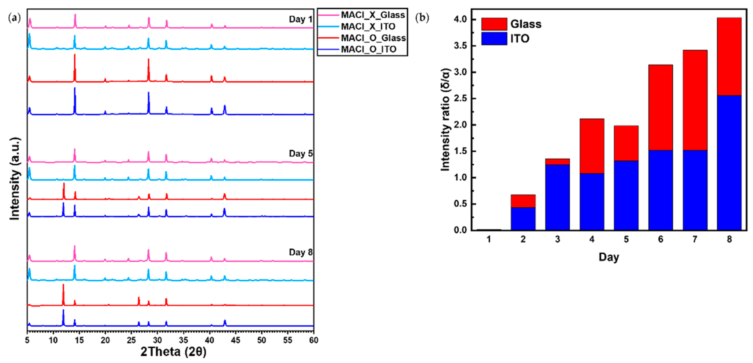
Figure 3.
(a) PL spectra of perovskite films on glass and ITO substrates under MACl_X and MACl_O conditions. (b) TRPL decay curves on glass and ITO substrates under MACl_X. (c) TRPL decay curves on glass and ITO substrates under MACl_O.
Figure 3.
(a) PL spectra of perovskite films on glass and ITO substrates under MACl_X and MACl_O conditions. (b) TRPL decay curves on glass and ITO substrates under MACl_X. (c) TRPL decay curves on glass and ITO substrates under MACl_O.
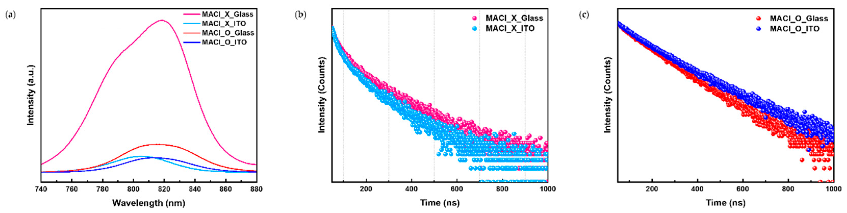
Figure 4.
(a) SEM images of perovskite films on glass substrates at Day 1. (b) SEM images of perovskite films on ITO substrates at Day 1. (c) SEM images of perovskite films on glass substrates at Day 8. (d) SEM images of perovskite films on ITO substrates at Day 8.
Figure 4.
(a) SEM images of perovskite films on glass substrates at Day 1. (b) SEM images of perovskite films on ITO substrates at Day 1. (c) SEM images of perovskite films on glass substrates at Day 8. (d) SEM images of perovskite films on ITO substrates at Day 8.
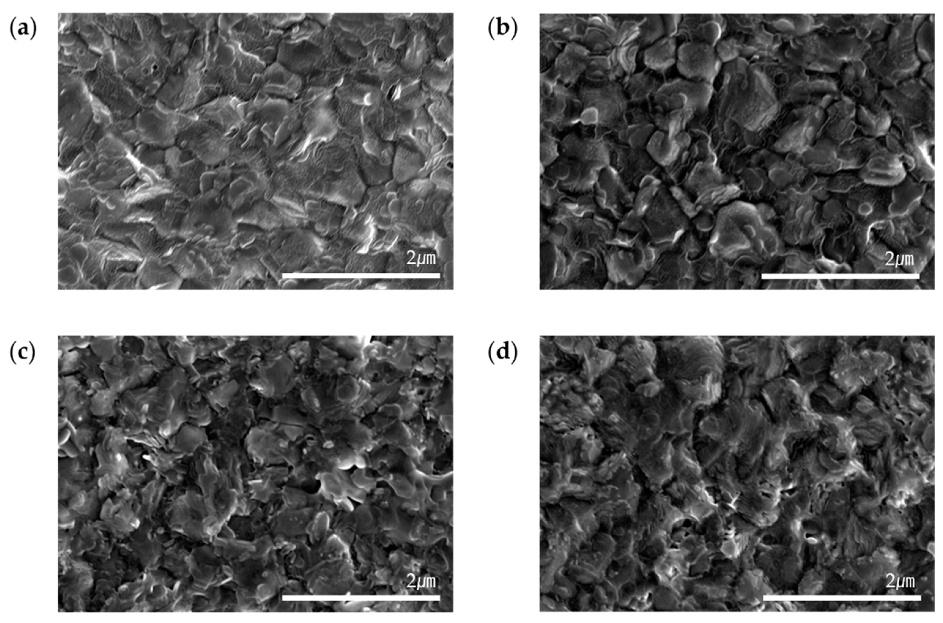
Figure 5.
(a) 3D AFM images of perovskite films on glass substrates at Day 1. (b) 3D AFM images of perovskite films on ITO substrates at Day 1. (c) 3D AFM images of perovskite films on glass substrates at Day 8. (d) 3D AFM images of perovskite films on ITO substrates at Day 8. (e) Schematic illustration of moisture infiltration mechanisms through the surfaces of glass and ITO substrates.
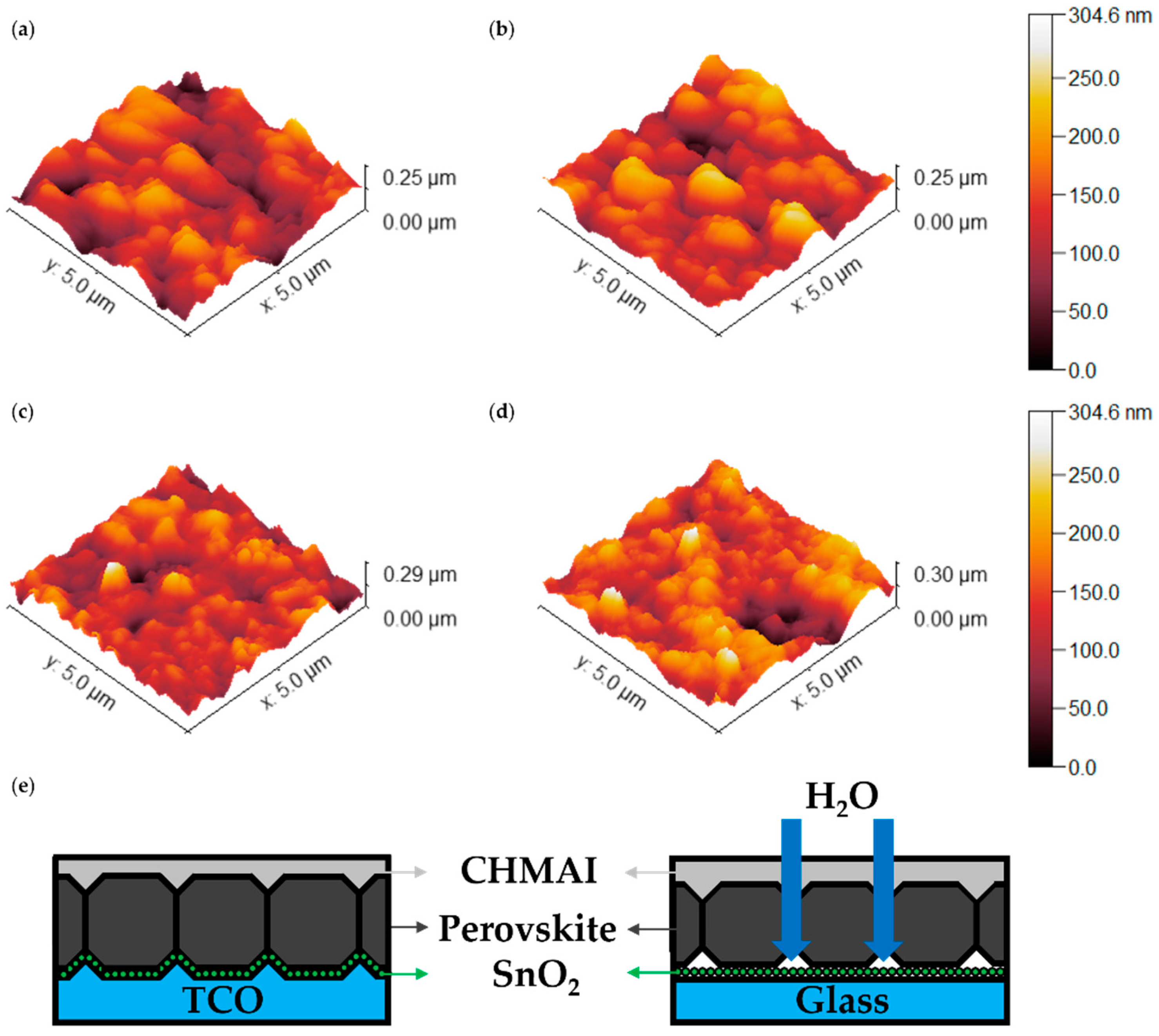
Figure 6.
(a) J-V curves for perovskite solar cells under MACl_X and MACl_O conditions, with forward and reverse scan data. (b) External quantum efficiency (EQE) spectra for devices under MACl_X and MACl_O conditions. (c) The normalized performance data of perovskite solar cells under MACl_O and MACl_X conditions for both the Island Type structure and the Etched ITO structure. (d) Schematic diagrams of the proposed Island Type structure (left) and the conventional etched ITO structure (right).
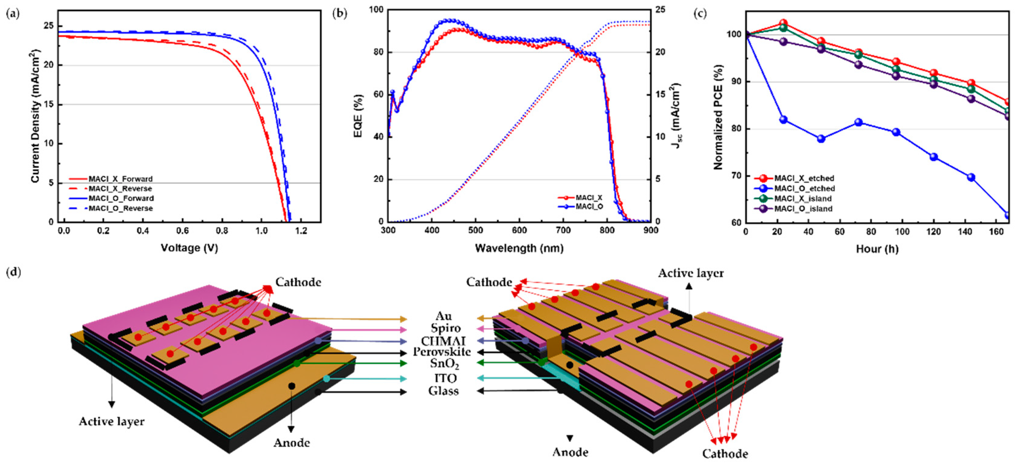

Table 1.
RMS roughness values of perovskite films on glass and ITO substrates at Day 1 and Day 8.
| Day | Glass | ITO |
|---|---|---|
| Day 1 | 38.55nm | 39.59nm |
| Day 8 | 41.99nm | 33.35nm |
Table 2.
Summary of photovoltaic parameters for perovskite solar cells under MACl_X and MACl_O conditions.
Table 2.
Summary of photovoltaic parameters for perovskite solar cells under MACl_X and MACl_O conditions.
| Condition | Type | PCE (%) | Voc (V) | Jsc (mA/cm2) | FF (%) | HI |
|---|---|---|---|---|---|---|
| MACl_X | Forward | 17.36 | 1.12 | 23.72 | 0.65 | 0.04 |
| Reverse | 17.99 | 1.13 | 23.56 | 0.68 | ||
| MACl_O | Forward | 20.83 | 1.14 | 24.28 | 0.75 | 0.03 |
| Reverse | 21.51 | 1.15 | 24.31 | 0.77 |
Disclaimer/Publisher’s Note: The statements, opinions and data contained in all publications are solely those of the individual author(s) and contributor(s) and not of MDPI and/or the editor(s). MDPI and/or the editor(s) disclaim responsibility for any injury to people or property resulting from any ideas, methods, instructions or products referred to in the content. |
© 2024 by the authors. Licensee MDPI, Basel, Switzerland. This article is an open access article distributed under the terms and conditions of the Creative Commons Attribution (CC BY) license (http://creativecommons.org/licenses/by/4.0/).
Copyright: This open access article is published under a Creative Commons CC BY 4.0 license, which permit the free download, distribution, and reuse, provided that the author and preprint are cited in any reuse.


