
Submitted:
11 December 2024
Posted:
12 December 2024
You are already at the latest version
Abstract
For application of non-metallic material in efficient vibration isolation, the polymer materials are used to construct a ST (sleeve type) isolator. The outside parts of ST isolator are made of PLA material, and the inside parts of ST isolator are made of TPU material. The polymer material model is linear elastic and isotropic. The numerical model of the ST isolator is calculated by using the finite element method. The static analysis and vibration isolation performance are analyzed. The numerical results show that when the ST isolator is under a force of 20000 N in vertical direction, the maximun deformation is 0.80 mm and the maximum stress is 2.68×10⁷ Pa. When under a force of 5000 N in horizontal direction, the maximun deformation is 1.44 mm and the maximum stress is 3.70×10⁷ Pa. The natural frequency of ST isolator is higher than 1800 Hz, and the fixed frequency of ST isolator is higher than 560 Hz. The harmonic analysis and transient analysis results show that the ST isolator has an efficient vibration isolation performance, especially when the ST isolator is fixed on a rigid foundation. This 3D printed ST isolator can be used in next engineering application.
Keywords:
vibration isolator
; vibration level difference
; numerical analysis
; vibration test
1. Introduction
In order to reduce the vibration impact of machines on surrounding instruments and structures, vibration isolators are usually used to isolate machines, and reduce the excitation force, so the foundation or the supporting base can have a mild vibration level. These vibration isolation performance values (load-carrying capability, force transmissibility, effective bandwidth, etc.) of vibration isolators play a vital role in the process of isolating excitation forces [1,2]. Due to the complexity and high cost of active vibration isolation systems, passive vibration isolators with broadband, strong vibration isolation capabilities and low cost have always been the ideal target [3,4,5,6].
In passive vibration isolation, these commonly used vibration isolators mainly include: metal springs, air springs, metal rubber springs, rubber vibration isolators and vibration isolation pads. Due to its good elasticity, metal springs can deform under the action of external forces, converting the mechanical energy generated by external forces into the elastic potential energy of the metal spring itself and storing it. When returning to the original state, it can also convert the stored elastic potential energy into mechanical energy and release it. Metal springs have these advantages without requiring additional power and are simple in structure. Therefore, they are widely used in the field of vibration isolation [7]. However, the damping coefficient of metal springs is very small, which results in poor stability of metal spring isolators without additional dampers. With the progress of research, a combined-springs vibration isolation shows positive and negative stiffness characteristics, which is used to effectively enhance vibration isolation performance [8,9] The inclined combined spring shows lower modal frequency and wider vibration isolation frequency band, so has weakened the corresponding periodic and random excitation disturbances. However, the combined spring is sensitive to the tilt angle, and external damping needs to be introduced to achieve better vibration isolation effect.
The advantages of air springs are good damping characteristics and low stiffness. However, the disadvantage is that the internal structure of the air spring is too complex, the structure requires proper maintenance, and the mathematical modeling requirements are high. In addition, an air pump is required during the use of air springs, which results in the use of air spring isolators that are bulky and have limited space [10].
The components of metal rubber vibration isolators are made of metal wires as raw materials, and the interior is mesh-like. It has a macromolecular structure similar to natural rubber, has the same elasticity and porosity as natural rubber, and has excellent damping and vibration reduction properties [11]. Therefore, vibration reduction and isolation components made of metal rubber are small in size and light in weight. The vibration isolators made of them are suitable for solving environments such as high and low temperatures, large temperature differences, high pressure, high vacuum, strong radiation, severe vibration and corrosion. Damping and vibration reduction under severe conditions, especially in some harsh environments [12]. However, its manufacturing technology is difficult and belongs to high-end manufacturing.
Rubber vibration isolators are made by curing and shearing rubber into various types of vibration isolators. Its performance and quality mainly depend on the rubber formula and vulcanization process. Due to the structural characteristics of rubber, the internal damping of the rubber material itself is relatively large, so it is very effective in high-frequency vibration isolation [13]. In other aspects, rubber shock absorbers also have the characteristics of small size, light weight, easy to be made into the required shape, and convenient installation. However, rubber also has the problem of aging easily, and it cannot be used in equipment that comes into contact with oil, hydrocarbons, ozone, or in places with high ambient temperatures. In addition, [14] the accurate rubber constitutive model is also an important basic research work for the analysis of the hyperelastic mechanical properties of ship vibration isolation rubber materials and the design calculation of vibration isolators. At present, multi-layer rubber composite structures are commonly used to achieve frequency reduction and enhanced vibration isolation design, such as rubber and steel sheet lamination, rubber and lead core combination and other vibration isolator structures [15], and studies have found that rubber core vibration isolators are more energy efficient than steel- Rubber laminated vibration isolators are more capable of isolating horizontal forces [16].
In addition to these above vibration isolators, common vibration isolation components also include vibration isolation pads of various materials, including cork, felt, fiberglass boards, etc., vibration isolation pads are cheap and can be spliced and overlapped to achieve different vibration isolation effects, but most of them are used just as a basis for a simple vibration isolation. The high static and low dynamic stiffness vibration isolator with superior vibration isolation effect relies on the spatial design of the spring[17,18].
Emerging 3D printing and its applicable materials provide technical support for the development of new vibration isolators [19,20]. A simple and compact adaptive magnetorheological fluid (MRF)-based vibration isolator (MRVI) was prepared using 3D printing method. A mask stereolithography (MSLA) 3D printer was used to fabricate rubber bellows and plastic cover components for MRVI [21]. The layered metamaterial structure was fabricated using 3D printing technology, and PETG (polyethylene terephthalate glycol) was used as the printing line of the fused deposition modeling printer. Vibration isolation studies obtained two main band gaps of 190~410Hz and 550~710Hz [22]. In addition, polymer materials such as 3D printing materials PLA and TPU have high mechanical stiffness and material molecular energy consumption [23,24], which is conducive to providing efficient vibration isolation and energy-consuming connections.
In vehicles and ships, the weight of every machine is heavy, and the operating speed range is wide. To solve the vibration isolation problem, vibration isolators should have some satisfactory parameter values such as large stiffness and high isolation performance in a wide frequency range. At the same time, taking diesel engine as an example, the reciprocating machinery not only induces vertical excitation, but also induces horizontal vibration excitation, so the vibration isolation engineering requires vibration isolators to have load-bearing ability and vibration isolation capability in both vertical and horizontal directions. In order to improve practicality and flexibility, vibration isolators are required to be easily constructed, have low material cost and less pollution. In order to meet the increasing requirements for vibration isolation levels and green vibration isolators, this paper uses 3D printing materials PAL and TPU to design a ST (sleeve type) vibration isolator, and this ST vibration isolator has high vertical stiffness and wide isolation frequency span through the sleeve core structure. At the same time, it also has large load-bearing and isolation capabilities in horizontal direction. The finite element method was used to simulate model and mechanical analysis of this new ST type vibration isolator, including static load capacity and excitation isolation effect. Vibration test of the ST vibration isolator is also carried out.
2. Construction of ST Isolator
As shown in Figure 1, the ST isolator is comprised by nine parts. Considering the 3D printing physical model in the future research, these component parts are made of TPU and PLA materials. No.1 part and No.2 part are made of PLA material, and constitute the top end and the bottom end respectively. No.6 part is made of PLA material, and forms a protective sleeve to enhance lateral stiffness. No.8 is a ring made of PLA material to enhance the inner connection. Other parts are all made of TPU materials, and these flexible TPU parts can have an energy absorption ability. In this new ST isolator, PLA parts are partitioned by TPU parts. This separation design of hard and soft structure results in discontinuous stiffness, and it meets the requirement of efficient vibration isolation.
3. Modeling of ST Isolator
According to the flow chart shown in Figure 2, the construction of ST isolator is drew in the solidworks software, and the geometry file in IGES format is imported into the numerical workplace. ST isolator is modeled by using the FEM. Static analysis, modal analysis and transient analysis are conducted in sequence. For numerical calculation, the grids of ST isolator are shown in Figure 3. The finite element mesh is comprised of 79730 nodes, and 449707 tetrahedral elements. In solid mechanics analysis, the elastic material model is used. For PLA material, the density is 1300kg/m3, the Young's modulus is 3.5×10⁹Pa, and Poisson’s ratio is 0.4. For TPU material, the density is 1220kg/m3, the Young's modulus is 6.2×10⁷Pa, and Poisson’s ratio is 0.3.
4. Mechanics Analysis and Discussion of ST Isolator
4.1. Static Load Analysis and Discussion
In application, isolator usually locates between machine and foundation as a soft connection and vibration isolation unit, so isolator is always in a compression state. As ST isolator is located on the rigid foundation, so the bottom of ST isolator is fixed during static load analysis. The constraint condition is shown in Figure 4, and the external force is on the top end. A vertical force Fz of 20000 N and the a horizontal force Fx of 5000 N in X-direction is respectively loaded on the top end. The deformation and stress values are shown in Figure 5.
In Figure 5(a), the ST isolator shrinks with the largest deformation 0.8 mm at the top, and the largest stress is 2.5×10⁷ Pa under the compression force 20000 N. In Figrue 5(b), the ST isolator tilts with the largest deformation 1.4 mm at the top, and the largest stress is 3.5×10⁷ Pa under the horizontal force 5000 N. This ST isolator has a large stiffness, and can support heavy machines in application.
4.2. Modal Analysis and Discussion
Beside the static loading capacity, the modality of ST isolator is important in vibration isolation. Table 1 shows the natural and the fixed vibration frequency. For natural vibration frequency, the ST isolator has a high frequency value, and the first natural frequency is 1849 Hz. When the ST isolator is fixed at the bottom, the vibration frequency decreases, and the first fixed frequency is 560.04 Hz. When both the bottom and the top are fixed, the first vibration frequency remains 1894.2 Hz as the same to the natural frequency, but the second vibration frequency is 1894.3 Hz, with a 8.43% decrease compared with the second natural frequency 2068.8 Hz. When order number is more than 2, the frequency of both the bottom and the top fixed is increased than frequency of natural and bottom fixed conditions.
Figure 6 shows vibration displacement distributions of ST isolator under free, bottom fixed and both ends fixed conditions, respectively. In natural mode, it is the concentric expanding at two ends in the first natural mode, and bending in the second and third natural modes. When the bottom of ST isolator is fixed, the vibration deformation locates at the top end, and it is bending in the first and second modes, and concentric expanding at the top end in the third mode. When both ends are fixed, vibration modes change to the twisting in the first and second modes, and concentric expanding in the third mode, especially, there is a large displacement in the middle and bottom parts. These comprised parts of ST isolator bring many local and variable vibration modes.
4.3. Transient Analysis and Discussion
As shown in Figure 7, a steel plate of 140mm×140mm×5mm (blue color) is the base of ST isolator. The fixed condition and simply-supported condition are considered to model the rigid and soft foundation in application. In the fixed condition, the steel plate is constrained at the bottom. In the simply-supported condition, the steel plate constrained at four sides. The top surface A and the bottom surface B are end surfaces of ST isolator.
According to the vibration evaluation, the vibration energy level difference VLDE is used to study the vibration isolation performance of ST isolator. VLDE value increases, and isolator has better vibration isolation effect.
Where, EB is the effective value of vibration energy at surface B on the bottom end, and EA is the effective value of vibration energy at surface A on the top end.
As the rotating speed of marine engines is 60~3000 r/min, the vibration frequency is 1~50 Hz. The expression of excited force F is in the expression of N, with the excited frequency =1 Hz, 20 Hz and 50 Hz, respectively for three excited excitation, and t is the time span. Base on the Expression (1) and data post-processing, both VLDE and deformation of ST isolator are analyzed in the numerical analysis.
Figure 8 shows values of VLDE in both simply supported and fixed constraints of ST isolator. When ST isolator is simply supported, the average VLDE value is 26.31 dB at 1 Hz, 26.25 dB at 20 Hz and 25.02 dB at 50 Hz. When ST isolator is fixed, the average VLDE value is 236.41 dB at 1 Hz, 236.93 dB at 20 Hz and 235.92 dB at 50 Hz. ST isolator has a stable and efficient isolation effect, with VLDE value higher than 25 dB when simply supported, and 235 dB when fixed. With the increase of excited frequency, VLDE value has a little drop less than 5% when simply supported, and 0.5% when fixed. As the different constraint conditions, it is better to locate ST isolator at a more rigid base for higher isolation effect.
Under excited vibration, ST isolator deformation is time-dependent. After a period of excitation vibration, Figure 9 shows characteristic deformations of ST isolator under 1 Hz in a time span from 5 s to 6 s. Figure 10 shows characteristic deformations of ST isolator under 10 Hz in a time span from 1 s to 1.1 s, and Figure 11 shows characteristic deformations of ST isolator under 50 Hz in a time span from 1 s to 1.02 s. Due to excitation force on the top end, the maximum displacement is at the circumferential edge, and its value is less than 5×10⁻³mm. Near the foundation connecting to the bottom end of ST isolator, the displacement is far less than 1×10⁻³mm.
4.4. Vibration Test and Discussion
In addition to the above numerical analysis, a physical model of ST isolator is constructed and its vibration test is done in this paper. The sinusoidal excitation testing is the continuous vibration of ST isolator at a certain frequency and amplitude, it can simulate the response analysis of ST isolator under vibration conditions in application. The excitation frequency span of concern is from 10 to 50 Hz. Under sinusoidal periodic vibration excitation, the acceleration response of the ST isolator is obtained to determine the acceleration vibration level[25,26].
In acceleration vibration level analysis, the drop of acceleration vibration level is an effective indicator for evaluating vibration isolation performance. The calculation formula for the drop of acceleration vibration level VLDa is 20 times the commonly used logarithm of the ratio of the input acceleration response value a1 to the output acceleration response value a2.
This experiment conducted a sinusoidal vibration test on the ST isolator within 50 Hz to test the isolation effect of the isolator on vibration at a fixed excitation frequency. As shown in Figure 12, the measurement is conducted on the vibration testing system platform. By connecting the control console, power amplifier and exciter, the excitation force is set by the control console, and is transmitted to the exciter through the power amplifier. After calibrated, two acceleration sensors (100 , 0.5~12000Hz) are installed at the top and bottom ends of ST isolator. In analysis, the input is the acceleration response on the top end, and the output is the acceleration response on the bottom end. According to formula (2), The VLDa (acceleration level drop) is calculated based on the input and output acceleration responses, so the isolation performance of ST isolator is analyzed in vibration test.
Table 2 shows vibration test results, and the excitation frequencies are 10 Hz, 20 Hz, 30 Hz, 40 Hz and 50 Hz, respectively. All VLDa values are above 1.80 dB, so ST isolator has a stable isolation effect in the range of 10 to 50 Hz. VLDa value in vibration test is a little lower than VLDa value in numerical analysis due to point response in vibration test.
In frequency sweep analysis, a sine signal continuously changing from 1 Hz to 200 Hz in a time span of 6s is excited on the ST isolator, to examine the vibration isolation behavior of ST isolatior within a specific frequency band. In the sine-sweep test, it is possible to quickly and intuitively understand the performance of ST isolator, so it is an important supplementary analysis for the above excitation vibration analysis in single frequency.
Figure 13 shows the time domain response of ST isolator at input (near excitation) and output (far from excitation). Two response curves are complex with harmonic signals. Besides that, the output response has a lower amplitude than the input response, and the response time delay between output and input is about 0.2s. After FFT, Figure 14 clearly shows the difference between input and output acceleration. Below 48 Hz, the output acceleration is lower than the input acceleration, as well as during the 120 Hz to 135 Hz. VLDa value is high to 12.5 dB around 45 Hz. The ST isolator has a specific isolation effect in the low-frequency band from 1 Hz to 50 Hz.
5. Conclusions
In this paper, a ST isolator made of PLA and TPU materials is modeled and numerically computed using the finite element method. The static deformation, modality, excited vibration response and vibration test are studied. The main conclusions are as follows.
A combination of PLA and TPU materials are very suitable for vibration isolator. The ST isolator in this paper has a load-bearing capacity high to 5000 N in horizontal direction and 20000N in vertical direction.
Due to the combination design of two materials and nine parts, the modality of this ST isolator is nonlinear to its constraints. When the bottom of ST isolator is fixed, the vibration frequency is the lowest.
This ST isolator has a good vibration isolation performance, especially when the base is fixed to form a rigid foundation. In frequency range of 1~50 Hz, VLDE value is more than 25 dB when ST isolator is simply supported, and 235 dB when fixed in numerical analysis. Vibration test results have verified the isolation effect of ST isolator based on point response.
With the superior load-bearing capacity, the isolation analysis with preload and vibration test of ST isolator in application are the interesting research in future.
Author Contributions
Conceptualization, investigation, writing—review and editing, S.Y.; data curation and software,L.J. and Y.Y.; data curation, D.W., Z.L. and L.F.; visualization, L.G. All authors have read and agreed to the published version of the manuscript.
Acknowledgments
This paper and some analysis are under the assistance of Xiamen Key Laboratory of Marine Corrosion and Intelligent Protection Materials, and it also tanks to Fujian Institute of Innovation for Marine Equipment Detection and Remanufacturing Industrial Technology.
Conflicts of Interest
The authors declare no conflict of interest.
References
- M. K. Ren, X. L. Xie, Z. W. Huang, and Z. Y. Zhang. Novel rubber-electromagnetic composite active/passive vibration isolator. J Vib Shock (In Chinese) 2021, 40(23), pp. 32-37.
- P. Gao, H. Liu, C. L. Xiang, and P. F. Yan. Study on torsional isolator and absorber comprehensive vibration reduction technology for vehicle powertrain. J Mech Eng(In Chinese) 2021, 57(14), pp. 244-252.
- W. Zhang, W. B. Wang, and S. B. Li. Dynamics and isolation performance of a nonlinear vibration isolator with a bistable cosine-shaped beam. J Vib Shock(In Chinese) 2022, 41(02), pp. 113-122.
- Kan Y, J.C. J, and Terry B. A novel integrated quasi-zero stiffness vibration isolator for coupled translational and rotational vibrations. Mech Syst Signal Pr 2021, 149, p. 107340.
- Y. C. Wang, S. Ma, Y. Li, and W. Xu. Application of active control technology on ship vibration and noise. J Naval Univ Eng(In Chinese) 2021, 33(04), pp. 56-64.
- Z. Q. Lu, D.H. Gu, D. Hu, L.Walter, and L.Q. Chen. A ring vibration isolator enhanced by shape memory pseudoelasticity. Appl Math Model 2021, 100, pp. 1-15. [CrossRef]
- K. Viswanath Allamraju, and K. Sharath Kumar. Finite element analysis of a spring isolator. Mater Today: Proc 2022, 60(p.2), pp. 949-952. [CrossRef]
- Q.L. Zhang, S.Y. Xia, D.L. Xu, and Z.K. Peng. A torsion-translational vibration isolator with quasi-zero stiffness. Nonlinear Dynam 2020, 99, pp. 1467-1488. [CrossRef]
- F. Zhao, J.C. Ji, K. Ye, and Q.T. Luo. An innovative quasi-zero stiffness isolator with three pairs of oblique springs. Int J Mech Sci 2021, 192, p. 106093. [CrossRef]
- V. Tiwari, S.C. Sharma, and S. P. Harsha. A comparative study on the behavior of ride quality due to deflated state of air spring using different properties of hyperelastic material. Int J Struct Stab Dy 2022, 22(10), p. 2241001. [CrossRef]
- X. Y. Zheng ,Z.Y. Ren, L.L. Shen ,B. Zhang, and H.B. Bai. Dynamic Performance of Laminated High-Damping and High-Stiffness Composite Structure Composed of Metal Rubber and Silicone Rubber. Materials 2021, 14(1), pp.187-187. [CrossRef]
- X.B. Cao, C. Wei, J.Q. Liang, and L.X. Wang. Design and dynamic analysis of metal rubber isolators between satellite and carrier rocket system. Mech Sci 2019, 10(1), pp.71-78. [CrossRef]
- H.W. Wang, S.P. Cao, X.H. Luo, Z.T. Zhang, and Q.J. Wu. Experimental study on the effect of rubber isolator on the vibration of piston pump. Proceedings of the 6th International Conference on Control, Mechatronics and Automation, Tokyo, 12-14 October 2018.
- Z. Jin, Y.L. Zhao, and X.Yang. Study on hyperelastic constitutive model of marine isolation rubber. J Ship Mech(In Chinese) 2023, 27(1), pp.144-152.
- S.J. Lee, G. T. Truong, J.E. Lee, S.H. Park, and K.K. Choi. Dynamic characteristics of combined isolation systems using rubber and wire isolators. Nucl Eng Technol 2022, 54, pp.1071-1084. [CrossRef]
- R. Rahnavard, and R. J. Thomas. Numerical evaluation of steel-rubber isolator with single and multiple rubber cores. Eng Struct 2019, 198, p. 109532. [CrossRef]
- Z.Q. Lu, and L.Q. Chen. Some recent progresses in nonlinear passive isolations of vibrations. Chin J Theor Appl Mech 2017, 49(03), pp. 550-564.
- X.T. Sun, J.W. Qian, Z.F. Qi, and J. Xu. Review on research progress of nonlinear vibration isolation and time-delayed suppression method. Adv Mech(In Chinese) 2023, 53(02), pp.308-356.
- Ali Z, Mahdi B, H. Ramin, P. Liam, M. Fard, and B.F. Rolfe. 3D-printed programmable mechanical metamaterials for vibration isolation and buckling control. Sustainability 2022, 14(11), p.6831, 2022.
- S. Herkal, M.M. Rahman, N. Satish, H V V Jayanthi, and A. Pulickel. 3D printed metamaterials for damping enhancement and vibration isolation: Schwarzites. Mech Syst Signal Process 2023, 185, p. 109819.
- Choi YT, Yoo B, Park J, Pines DJ, and Wereley NM. Design and performance of a 3D-Printed magnetorheological fluid-based adaptive vibration isolator. Front Mater 2023, 10, p.1142590. [CrossRef]
- A. Winner, N. Hieu, and B. Hamzeh. Layered metamaterial beam structures with local resonators for vibration attenuation: model and experiment. Front Mech Eng 2021, 7, p.768508.
- R. Davood, S. Kianoosh, P. Mostafa, A. Mohammad, S. Elyas, G. Ismaeil, B. Majid,A. Karen,B. Mahdi,and B. Mostafa. Shape memory performance assessment of FDM 3D printed PLA-TPU composites by Box-Behnken response surface methodology. Int J Adv Manuf Technol 2023, 127(1-2), pp. 935-950.
- F. Vahid, K. H. Ali, G. Vahabodin, D. Goldis, and O. Maryam. Hydroxyapatite/TPU/PLA nanocomposites: morphological, dynamic-mechanical, and thermal study. Green Process Synth 2022, 11(1), pp. 996-1012.
- Sangharatna M. Ramteke, H. Chelladurai, M. Amarnath. Diagnosis of liner scuffing fault of a diesel engine via vibration and acoustic emission analysis. J Vib Eng Technol 2019,10, pp: 1-19. [CrossRef]
- Seokhwon Lee, Jongdae Kang, Sungwook Park. Measurement and Modeling of crank train friction in light-duty diesel engines. J Mech Sci Technol 2020, 34(2), pp:889-903. [CrossRef]
Figure 1.
Sketch of ST isolator (1 – top cover; 2 – bottom base; 3 – core A; 4 – core B; 5 – bushing; 6 – casing; 7 – ring; 8 – ring; 9 – ring).
Figure 1.
Sketch of ST isolator (1 – top cover; 2 – bottom base; 3 – core A; 4 – core B; 5 – bushing; 6 – casing; 7 – ring; 8 – ring; 9 – ring).
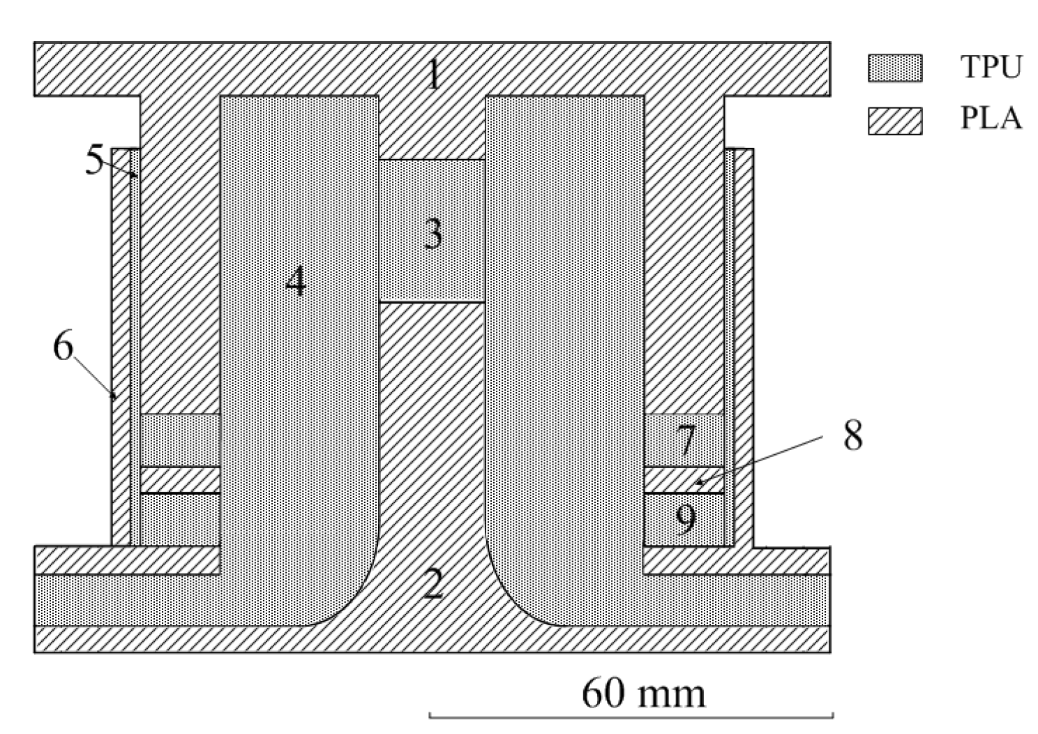
Figure 2.
The flow chart of mechanical analysis.
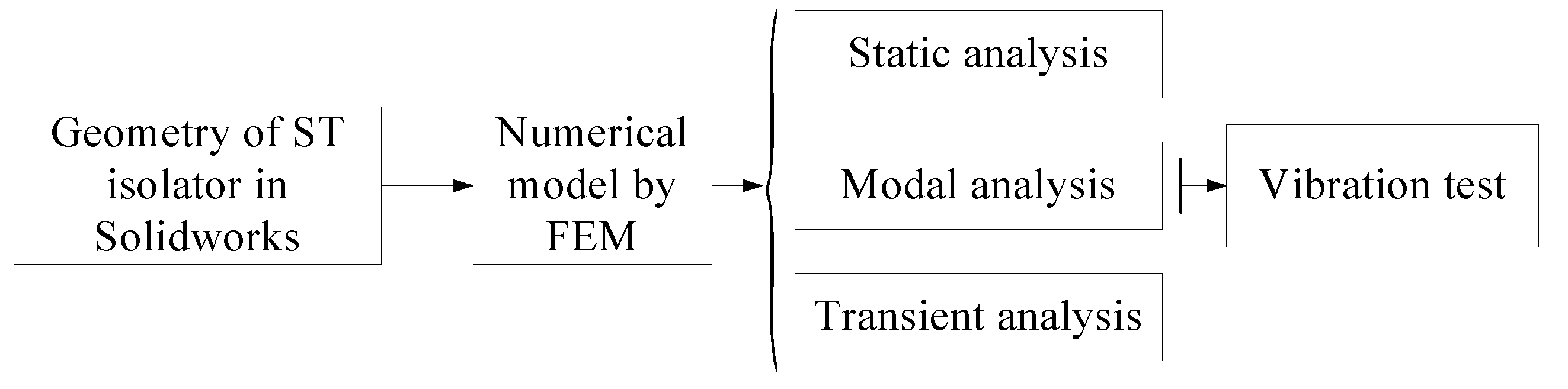
Figure 3.
Geometry appearance and grids of ST isolatorhis: (a) Geometry; (b) Grids.
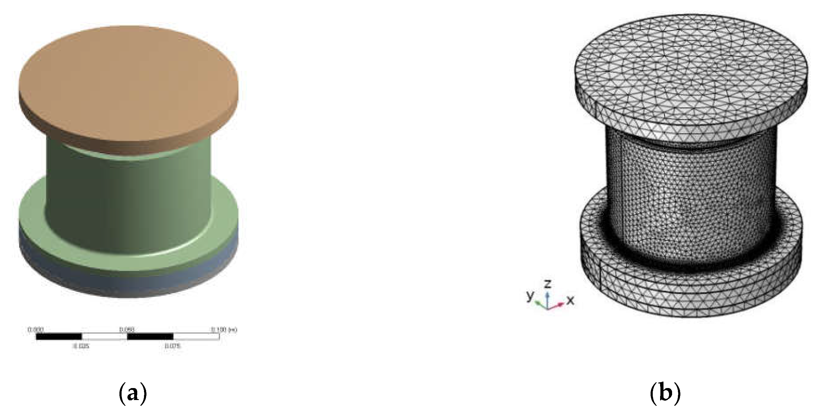
Figure 4.
Load and constraint of ST isolator.
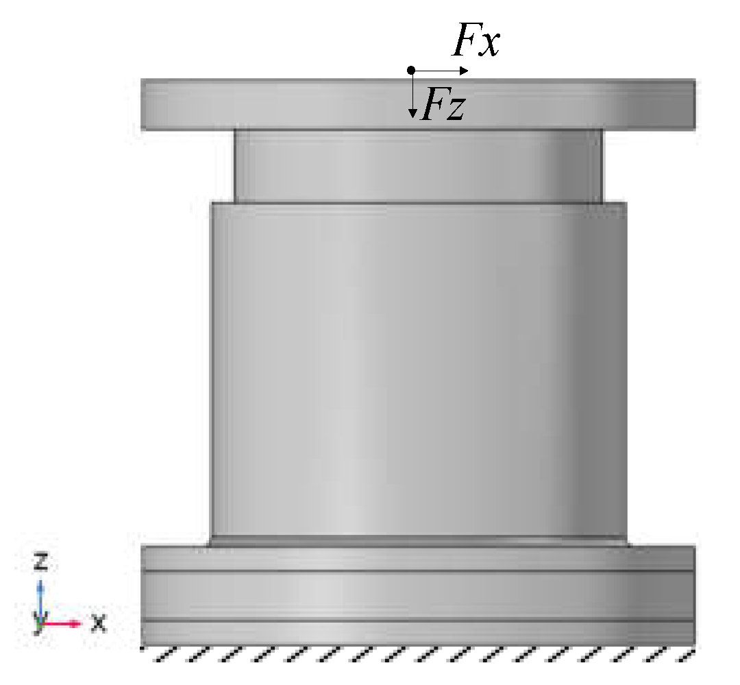
Figure 5.
Deformation and stress of ST isolator under static load: (a) Compression force 20000 N in Z-direction; (b) Force 5000 N in X-direction; (i) and (iii) Displacement; (ii) and (iv) Stress.
Figure 5.
Deformation and stress of ST isolator under static load: (a) Compression force 20000 N in Z-direction; (b) Force 5000 N in X-direction; (i) and (iii) Displacement; (ii) and (iv) Stress.
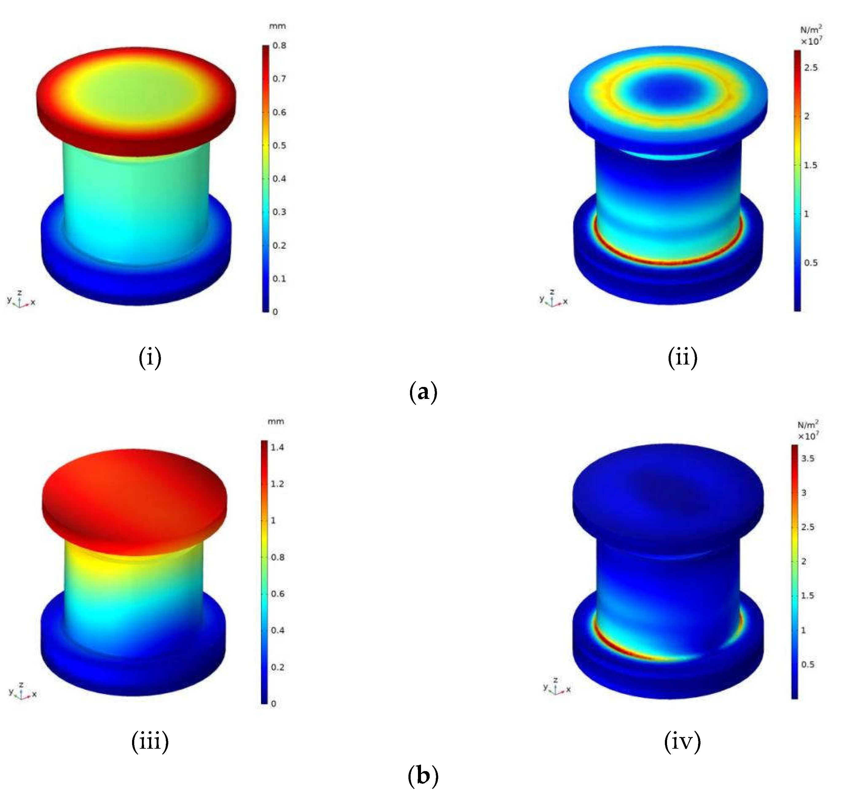
Figure 6.
The modal displacement distribution of ST isolator: (a) The first order modality; (b) The second order modality; (c) The third order modality; (i) Natural; (ii) Bottom fixed; (iii) Bottom and top fixed.
Figure 6.
The modal displacement distribution of ST isolator: (a) The first order modality; (b) The second order modality; (c) The third order modality; (i) Natural; (ii) Bottom fixed; (iii) Bottom and top fixed.
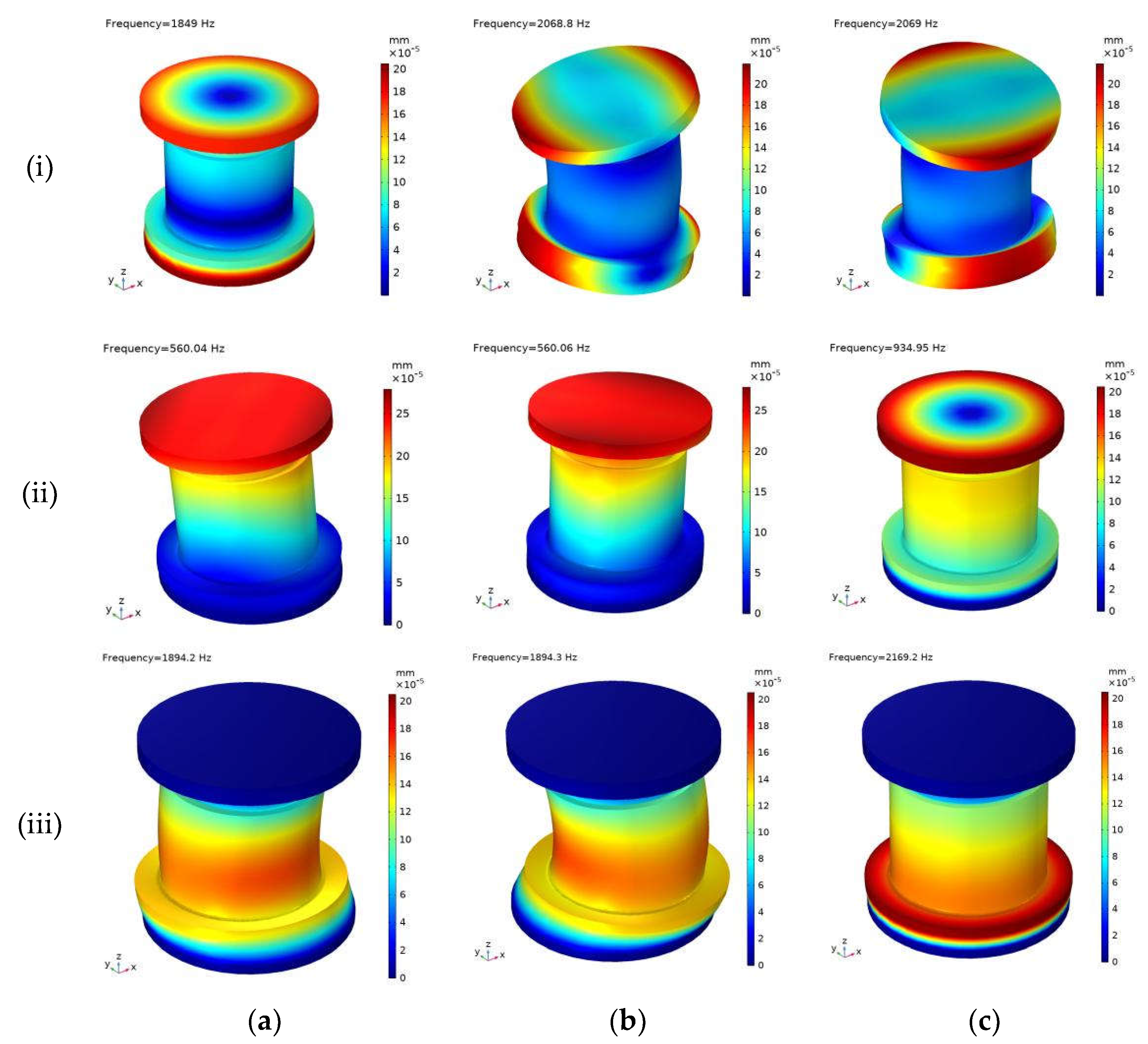
Figure 7.
Load and constraint of ST isolator.
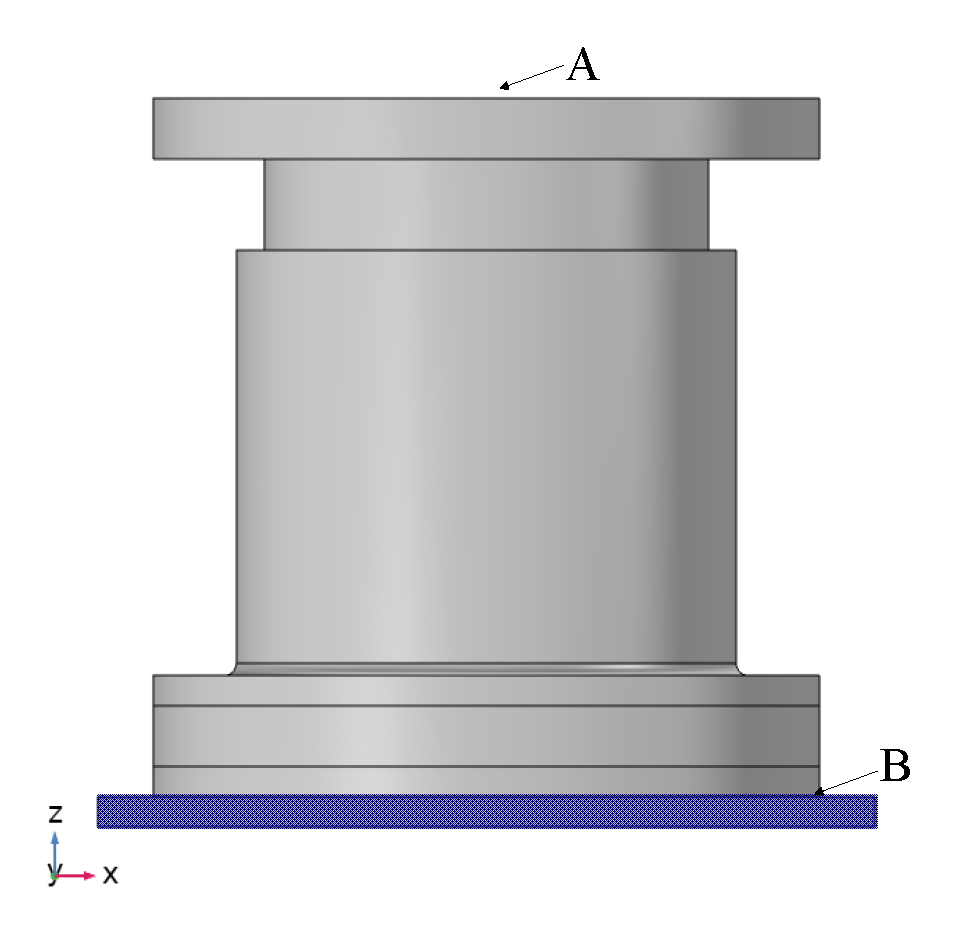
Figure 8.
VLDE of ST isolator: (a) Excited frequency is 1 Hz; (b) Excited frequency is 10 Hz; (c) Excited frequency is 50 Hz.
Figure 8.
VLDE of ST isolator: (a) Excited frequency is 1 Hz; (b) Excited frequency is 10 Hz; (c) Excited frequency is 50 Hz.
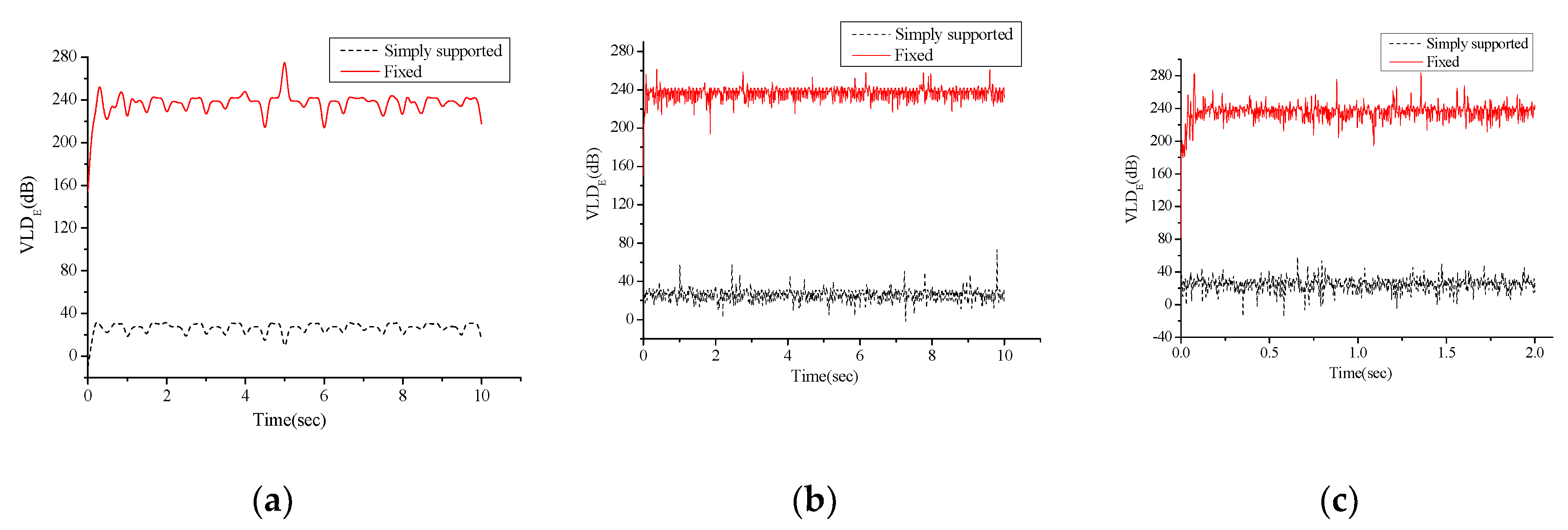
Figure 9.
Deformations of ST isolator under excitation 1Hz: (a) ST isolator is simply supported; (b) ST isolator is fixed.
Figure 9.
Deformations of ST isolator under excitation 1Hz: (a) ST isolator is simply supported; (b) ST isolator is fixed.
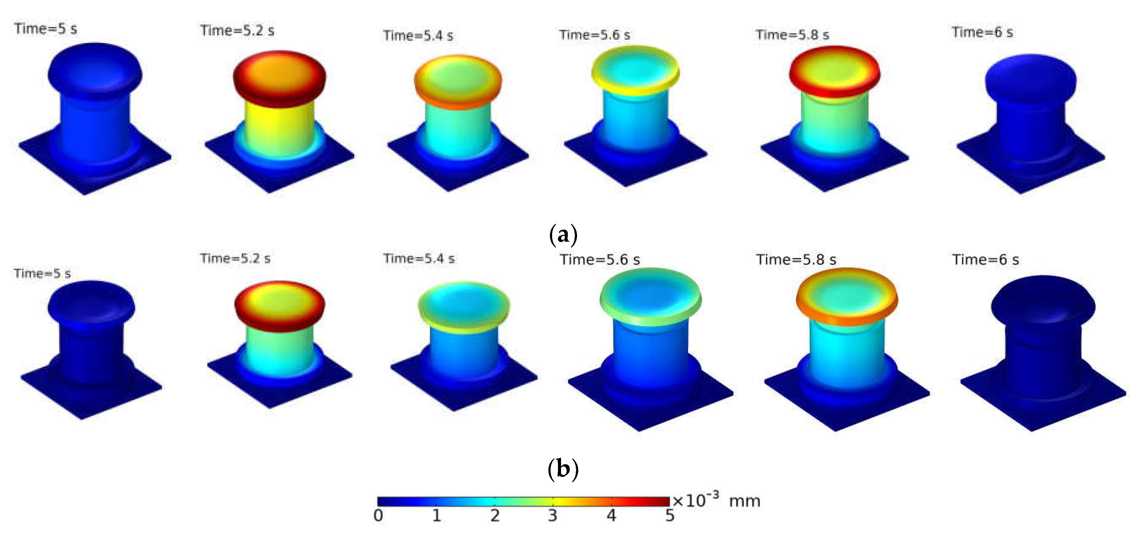
Figure 10.
Deformations of ST isolator under excitation 10Hz: (a) ST isolator is simply supported; (b) ST isolator is fixed.
Figure 10.
Deformations of ST isolator under excitation 10Hz: (a) ST isolator is simply supported; (b) ST isolator is fixed.
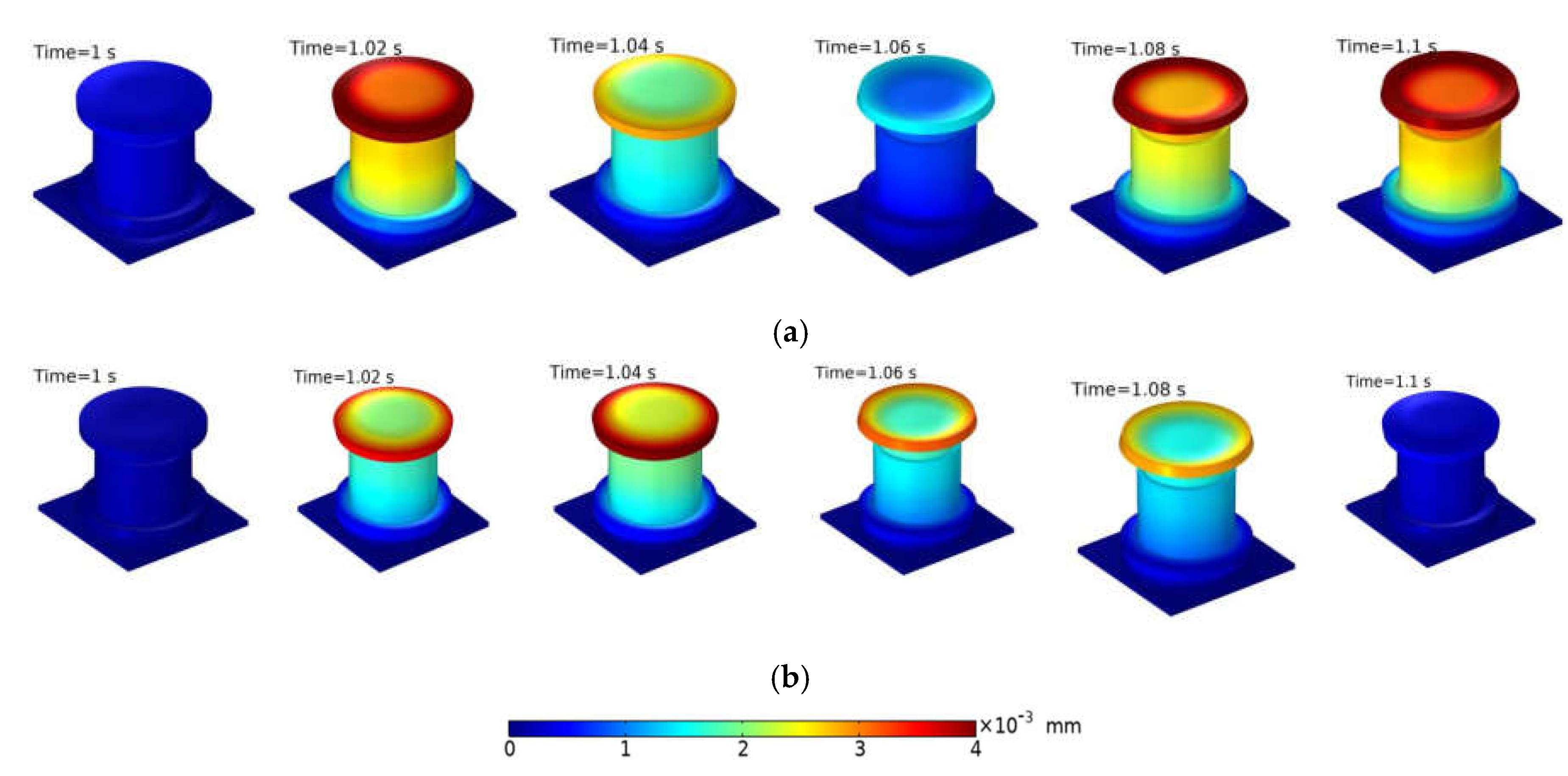
Figure 11.
Deformations of ST isolator under excitation 50 Hz: (a) ST isolator is simply supported; (b) ST isolator is fixed.
Figure 11.
Deformations of ST isolator under excitation 50 Hz: (a) ST isolator is simply supported; (b) ST isolator is fixed.
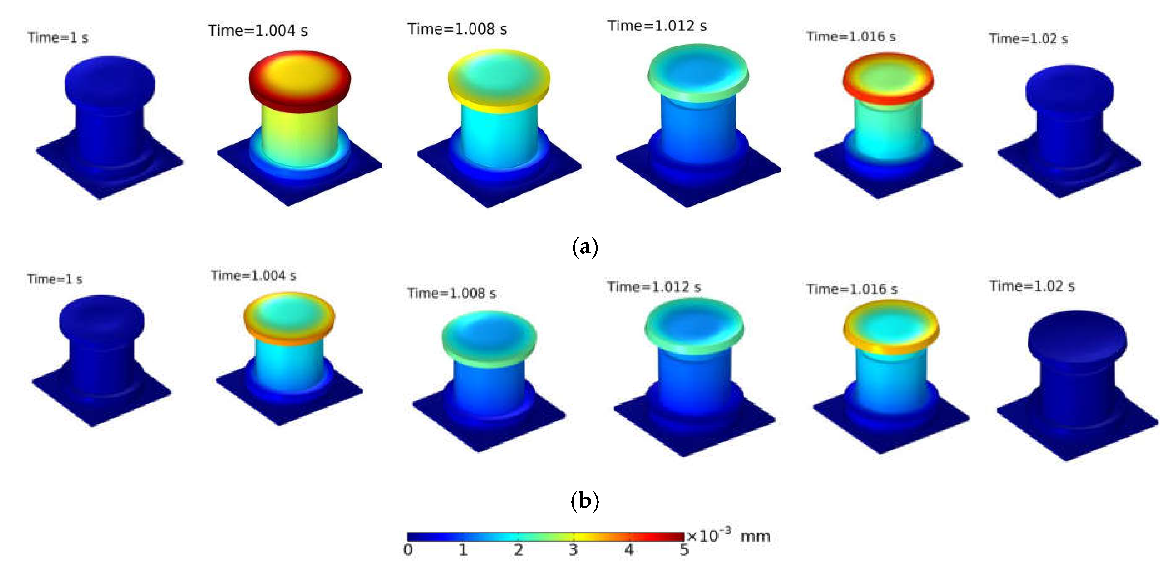
Figure 12.
Vibration test system.
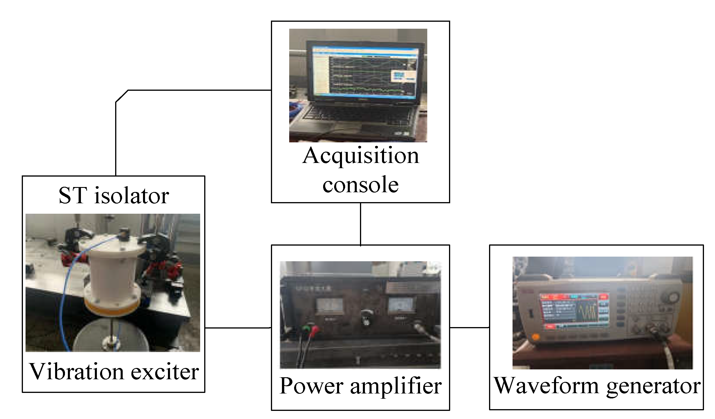
Figure 13.
Time-domain response of ST isolator in vibration test: (a) Input; (b) Output.
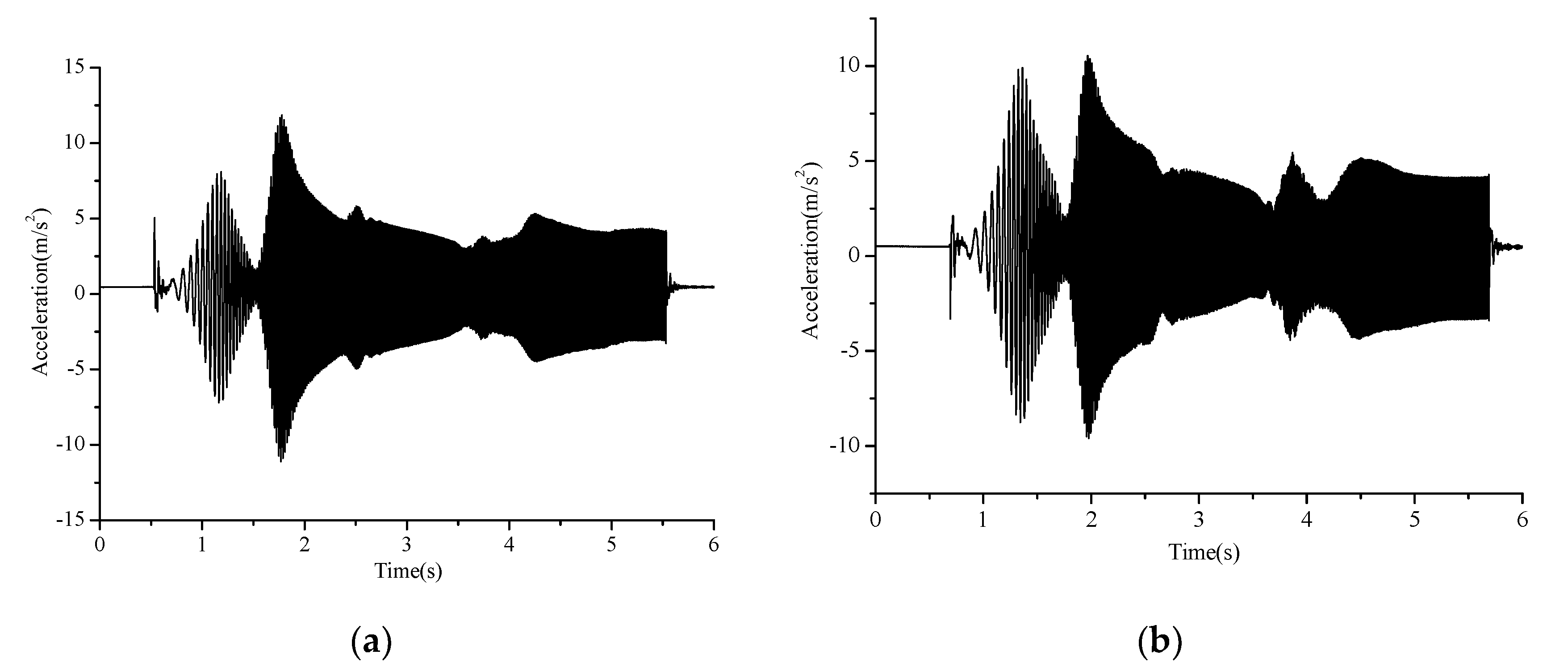
Figure 14.
Frequency-domain response of ST isolator in vibration test: (a) Accelerationn response; (b) VLDa of ST isolator.
Figure 14.
Frequency-domain response of ST isolator in vibration test: (a) Accelerationn response; (b) VLDa of ST isolator.
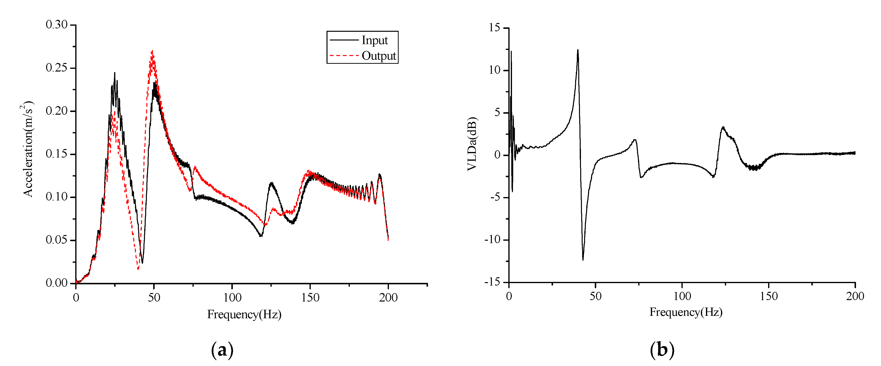

Table 1.
Modal frequency of ST isolator (Hz).
| Order number | Natural | Bottom fixed | Bottom and top fixed |
|---|---|---|---|
| 1 | 1849 | 560.04 | 1894.2 |
| 2 | 2068.8 | 560.06 | 1894.3 |
| 3 | 2069 | 934.95 | 2169.2 |
| 4 | 2361.7 | 1441.4 | 2823.9 |
| 5 | 2362 | 1634.6 | 2824 |
Table 2.
Acceleration values of ST isolator in vibration test.
| Frequency(Hz) | Input(m/s2) | Output(m/s2) | VLDa(dB) |
|---|---|---|---|
| 10 | 0.074 | 0.060 | 1.82 |
| 20 | 0.486 | 0.379 | 2.16 |
| 30 | 0.382 | 0.273 | 2.92 |
| 40 | 0.299 | 0.120 | 7.93 |
| 50 | 0.316 | 0.234 | 2.61 |
Disclaimer/Publisher’s Note: The statements, opinions and data contained in all publications are solely those of the individual author(s) and contributor(s) and not of MDPI and/or the editor(s). MDPI and/or the editor(s) disclaim responsibility for any injury to people or property resulting from any ideas, methods, instructions or products referred to in the content. |
© 2024 by the authors. Licensee MDPI, Basel, Switzerland. This article is an open access article distributed under the terms and conditions of the Creative Commons Attribution (CC BY) license (http://creativecommons.org/licenses/by/4.0/).
Copyright: This open access article is published under a Creative Commons CC BY 4.0 license, which permit the free download, distribution, and reuse, provided that the author and preprint are cited in any reuse.


