
Submitted:
10 December 2024
Posted:
11 December 2024
You are already at the latest version
Abstract
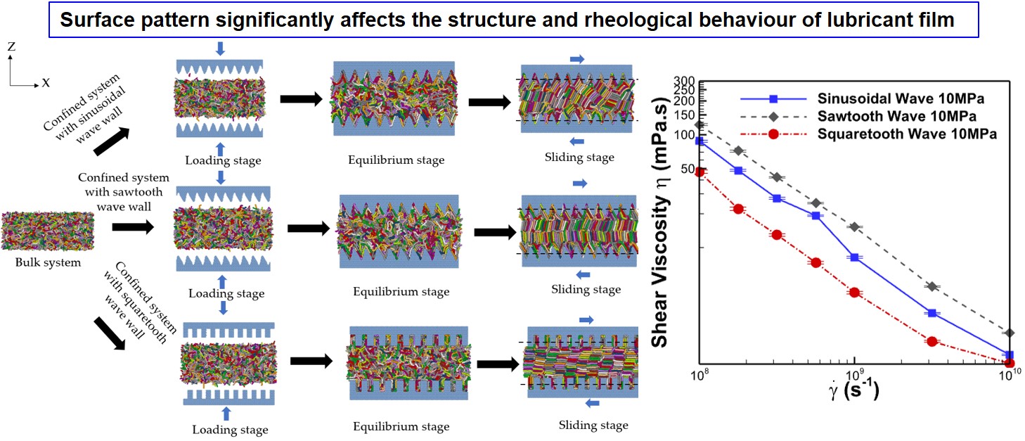
Understanding lubrication at the nanoscale is essential for reducing friction. While alkanes, the primary component in most lubricants, have been extensively studied for their molecular structure's impact on rheology and behaviour when confined by solid surfaces, the influence of confining surface texture remains underexplored. This research uses molecular dynamics simulations to investigate the rheological behaviour of thin film lubrication between various patterned rough surfaces. The study focuses on three types of wave-patterned surfaces: sinusoidal, sawtooth, and squaretooth. Hexadecane, a linear alkane, is used as the lubricant. The simulations examine the effects under different normal loads and shear rates. Surface patterns significantly influence the formation and structure of crystalline bridges. This, however, depends on shear rates and normal loads. Under low normal load and shear rate conditions, the sawtooth wave-patterned surface exhibits the highest viscosity by forming crystalline bridges with molecular orientation perpendicular to the shear direction. The squaretooth patterns exhibit the lowest viscosities due to the nematic order in crystalline bridges with molecules aligned in the shearing direction. The lubricant viscosity with a sinusoidal wave-patterned surface is an intermediary with disordered crystalline bridge groups formed with random molecular orientation. The lowest viscosity provided by the squaretooth pattern surface persists for the transitory state as well as the steady state on both high and low loads and over a wide band of shear rates. However, the extent of the difference in shear viscosity is reduced at higher normal loads. This research provides valuable insights for designing nanoelectromechanical systems (NEMS) and other applications where boundary conditions are critical to lubrication.
Keywords:
surface texture
; patterned wall
; rough surface
; rheology behaviour
; hexadecane
; molecular dynamics
; crystalline bridge
1. Introduction
Researchers have widely investigated thin film lubricants under boundary conditions because they are essential in many applications, especially for Nano Electromechanical Systems (NEMS) [1,2,3,4]. Understanding the behaviour of molecular thin film lubricants is also essential for replicating the conditions in boundary lubrication regimes relevant to tribology. For these applications, the dimensions are usually smaller than 50-100 nm [5]. Under such nanoscale conditions, the molecular length is typically comparable to the film thickness and surface roughness. As a result, continuum mechanics may not be valid, and experiments may find it challenging to observe molecular behaviours. Molecular dynamics simulation (MDS) [6,7] and its coarse grain versions [8] have been used as an effective tool for studying thin film lubrication and rheology. Many researchers have reported improving lubrication by mixing different lubricants and particles and designing lubricants of different molecular structures [9,10,11,12,13,14] to affect its rheological and tribological behaviour. However, the effect of surface texture has not been explored.
Boundary lubrication under two atomically smooth surfaces has been researched using MDS over the last few decades [15,16,17,18,19,20,21,22]. Alkanes have been studied widely due to their importance as the main component of mineral oil-based lubricants. It has been shown experimentally and by simulations that the linear alkanes experience a transition to rigidity with a significant increase in shear viscosity when confined between two smooth surfaces as an ultra-thin film lubricant [16]. The structural origin of this ultra-high viscosity of short alkanes (dodecane) was discovered by Jabbarzadeh et al. to be the formation of crystalline bridges [19]. They also showed that the crystalline bridges could be destroyed at shear rates higher than . Furthermore, in 2005, Jabbarzadeh et al. [18] highlighted that layer slippage is associated with forming aligned crystalline bridges in the flow direction that leads to a low friction state of dodecane film between mica solid surfaces, similar to a solid lubricant. This is the ideal condition for wet lubrication of solid surfaces.
Observation of these rigid films is also reported for other materials. Krim et al. [23] reported that Kr gas condensate layers undergo solidification on a gold surface, and the morphology of confining surfaces affects the solid layers more than the liquid. Jabbarzadeh et al. [24] showed that interaction strength between confined surfaces and fluid and the stiffness and density of walls can also affect the rheology behaviour under shear flows. The effect of surface type and operation conditions have also been investigated. Ta et al. [22] analysed the rheological behaviour of hexadecane confined with different iron and iron oxide solid walls. They concluded that the shear stress increases with the increase of the loading pressure. Also, they observed that different materials with different surface structures will affect the ordering and slip of the lubricant. They found that the Fe2O3 solid surface has a high friction, and the degree of ordering is low. The effect of properties of solid surfaces on the rheology behaviour of thin film lubricants has also been investigated [26,27].
However, the effect of surface texture is still a puzzle, and only a few researchers have reported on its effect. According to Richardson [28], three length scales are essential for the flow of confined fluids. These include the fluid's molecular length, the solid wall's roughness, and the fluid's bulk motion. Different relative length scales may lead to a change in the wall slip condition. Thompson and Robbins [29] state that the geometry of the confined solid surfaces and the interactions between surfaces and lubricants can influence the structure and slip length. The effect of relative length scales of the molecules and roughness parameters are reported by Jabbarzadeh et al. [30]. They studied the effect of the roughness period and roughness depth for sinusoidal-patterned surfaces on rheological properties, film structure and hexadecane slip behaviour. They reported that the lower the roughness period, the more likely the molecules will be trapped in the space between the valleys and peaks of the solid wall. They also found that with the increase of the roughness amplitude, there will be an increased trend of the velocity in the middle region, and the density peak will move inward from the wall.
Hu et al. [31] studied the Couette flow of simple Lennard-Jones liquids confined by a hydrophobic smooth flat surface at the top and a hydrophobic squaretooth patterned lower surface. They found the friction was lower on the squaretooth patterned wall than the upper flat surface due to the lower liquid-solid contact area on the grooved surface. At higher loads, liquid molecules were trapped in the valley, increasing friction force.
While the effect of surface patterning on wettability [32] and crystallization [33] of liquid alkanes are studied at the nanoscale, its effect on rheology and friction is unexplored. In particular, the effects of different geometrical shapes on surface texture are barely discussed. This work presents the effect of surface patterning shape for 1D groove patterning on the confining surface. Here, we consider sinusoidal, sawtooth, and squaretooth wave-patterned surfaces. Such patterns are studied in macroscale systems by tribologists and rheologists in different applications [31,32,33,34,35,36,37]. However, they have not been investigated for nanoscale applications when alkanes are used as lubricants. Alkanes are the main component of mineral-oil-based lubricants, which many researchers have studied widely [38,39,40,41,42]. Therefore, this research will mainly study hexadecane's rheological and tribological behaviours when confined by these three different patterned walls. We will also study the effect of normal load and shear rate on the results.
2. Materials and Methods
2.1. Molecular Model
In this project, hexadecane C16H34, a linear alkane, is chosen to analyze the rheology behaviour because hexadecane is widely used as a significant component in commercial organic lubricants and is a mineral-based oil [39]. Alkanes are used as a model lubricant in molecular simulations, and their potential parameters are readily available. The length of the hexadecane molecule is about 1.8 nm [24]. The hexadecane model used in this research is an extension based on Ryckart and Belleman's model [43], where CH3 and CH2 are treated as single interaction sites referred to as united atoms (UA). Many researchers and our group have utilized this united atom model to study frictional [6,7] rheological [17,18,19,20], crystallization [33,44] and wetting properties [45].
Both intermolecular and intramolecular interactions are considered in this molecular model. The intermolecular interactions [30] are governed by the shifted 6-12 Lennard-Jones potential given by Equations (1) and (2).
Where energy parameter of each atom; is the length parameter of each atom; r is the distance between interacting atoms, which is measured from the centre of the particles; is the truncation cut-off radius set at 1 nm (2.5 σ).
Intramolecular interactions [46], including band angle, bond stretching, and torsion, are included in the model. These interaction parameters are provided in Table 1.
Initially, the hexadecane model is built in a bulk state by applying periodic boundaries in all three directions. [49]. The bulk system is simulated with 4616 hexadecane molecules. The simulation at this stage is done at the NVT ensemble (The number of atoms, the volume of the simulation box, and the temperature are kept constant). The dimensions of the bulk system in X and Y directions are chosen to fit the wall dimensions in the X and Y direction for intended confined simulations. The thickness of the liquid slab produced at this stage is 9.897 nm (see Figure 2).
2.2. Bulk Simulations
The system is equilibrated at a density of 769 kg/m3, corresponding to a temperature of 300 K in an orthogonal simulation box. The SLLOD algorithm is used for this stage, with the temperature kept constant at 300 K using a Gaussian thermostat [50]. This system is equilibrated, allowing the molecular configuration to take its natural state. The equations of motion are integrated by the Verlet algorithm at a timestep of 4.72 fs using an in-house program developed by the second author.
2.3. Confining Surfaces Model
Confining surfaces are all atomically structured walls made from FCC crystal structure with their [111] facet parallel with the XY plane. All surfaces have a lattice constant of gold (a=0.408 nm). The atomic diameter and mass of the wall atoms are σw= 0.288 nm and m=192.027 amu. In order to analyze the effect of surface texture on rheological behaviour, rough wavy walls with different wall patterns are created. The patterns are created by cutting off the atoms from an orthogonal crystal block. The block is thick enough to accommodate the intended roughness pattern. Here, we have created 1D grooves along the Y-axis. Three grooved patterns are created, including sinusoidal, sawtooth and squaretooth patterns. The groove's direction is perpendicular to the shearing in the X direction. Therefore, the profiles created must perfectly match the wall’s dimension in the X direction, forming a periodic pattern. Consequently, as sliding occurs in the X direction, the periodic wave function’s periodic images align seamlessly, creating the illusion of an endless patterned wall in the X direction. The roughness amplitude (half the groove’s depth) and period (peak-to-peak distance) are the same for all surfaces. The roughness amplitude is the closest possible for a specific lattice size. The roughness amplitude and period for all surfaces were respectively 1.178 and 2.452 nm, producing grooves of 2.356 nm depth comparable to the length of a hexadecane molecule. The three surface textures are shown in Figure 1, which are the snapshots taken from simulations. The sinusoidal pattern is similar to the sawtooth pattern due to the high roughness frequency (low periodicity), but the differences between them can still be distinguished where the sinusoidal pattern has a symmetrical shape. However, the sawtooth pattern is not symmetrical, with the teeth inclined to the side in the direction of sliding. In microscopy tribology studies, the roughness of a few nanometers is always used in tribological experiments [53]. Thus, our roughness is also close to the real-world condition. The number of wall atoms for sinusoidal, sawtooth and squaretooth surfaces was 77520.
2.4. Confined Simulations
For the confined system, the equilibrated configuration of the bulk system of the lubricant molecules is initially placed between the confining surfaces. There are three steps in the simulation of confined systems, involving step 1 - applying the normal load to the walls. In the loading step, the motion of the solid atoms in the z direction is based on the Nosé-Hoover algorithm governed by Equation (3) [50].
Where ζ is the damping constant, A is the area of the solid surface; is the instantaneous normal stress; is the desired normal stress. Also, a profile unbiased thermostat is used [50]. This step moves the two confining surfaces to squeeze the lubricating film at the desired normal load.
The rheology behaviour of hexadecane is examined with three different surface textures under 10, and 300 MPa constant load at seven different shear rates, respectively, which is shown in Figure 2, and the whole system is kept at room temperature at 300 K.
Step 2 – Equilibrium: The system is equilibrated for 37.673 ns at this stage. This relatively long equilibration is necessary for the structures to form in the lubricant.
Step 3 – Shearing stage: different shear rates are applied by sliding the two walls in opposite directions at the same velocity for a given nominal shear rate. The wall sliding velocity Uw depends on the film thickness (h) and shear rate where Uw= This approach creates a boundary-driven Couette shear flow across the lubricant thickness. Subsequent simulations utilize the preceding step's atomic configuration of coordinates and velocities. The steps are shown in Figure 2. A parallel algorithm is used in the MDS to achieve speedup with good computational efficiency [54,55]. The walls’ sliding velocity ranges from 0.42 to 47.69 m/s.

Table 1A.
Wall type, load, shear rate and simulation time for various boundary-driven simulations.
| Wall Types | Normal Loads (MPa) | Shear Rate () | Time (ns) |
| Sinusoidal Sawtooth Squaretooth | 10 and 300 | 18.8 | |
2.5. Structural Characterization
In order to quantify the formation of crystalline bridges, Frenkel and Eppenga's second and fourth-rank correlation functions are used to identify the orientation order in the plane, which are given by equations 4 and 5 [20].
Where is the orientation angle between molecules i and j. The angled brackets indicate these are time-averaged values. If molecules are parallel, a positive value can be found in and . Whereas for perpendicular alignment between pair molecules is negative and is positive. Therefore, in a tetratic order, where both parallel and perpendicular alignment between molecules exist, can be detected. On the other hand, a nematic order, where parallel alignment is dominant between molecules, yields . These pairwise structural parameters can be measured locally for molecules within cylindrical domains whose diameter is equal to the length of molecules and their axis parallel to the Z axis. In that case, we note them as (stack) and (stack). Similarly, we can detect global orientation order within the entire film by considering all molecules. In this case, we denote them as and .
In order to have a comprehensive quantification of the order of the film confined by the rough surface, another order parameter is also used. This order parameter is used to measure the shear-induced alignment of molecules in Couette flow, which is calculated through order tensor S. This order tensor is a traceless tensor governed by Equation (6) [51].
Where is the unit vector along with molecular longest axis of inertially equivalent ellipsoid; I is the unit tensor. The order parameter is the largest eigenvalue of the order tensor, which ranges from 0 to 1, meaning from disorder to perfect orientation.
3. Results and Discussions
3.1. Equilibrium Stage
The system is equilibrated at each loading of 10 and 300 MPa for 37.672 ns without applying any shear. In the equilibrium stage, we use (stack), and (stack) values to quantify the crystalline bridges for all cases to make them comparable. We have shown the final configuration of the molecular structure in Figure 3 in snapshots for the loads of 10 and 300 MPa. Under 10 MPa, the sinusoidal wall exhibits crystalline bridges forming in small groups. The molecules in each group are oriented relative to those in other groups in alternate parallel or perpendicular alignments within the X-Z plane. For the sawtooth wall, the crystalline bridges form in parallel alignment, and (stack)~(stack)≈0.4 indicate nematic order within the film, albeit the order direction is not parallel to the XY axis. We can see within each domain that the molecular axis is inclined and runs parallel to the longer inclined surface of the grooves. For the squaretooth wall, crystalline bridges form in parallel and perpendicular alignment in the X-Y plane, and values of (stack) and (stack) ≈0.4 indicate tetratic order is dominant.
In contrast, under 300 MPa, for all cases, we can find the crystalline bridges form in small groups in a disordered manner. Here, the calculated (stack) and (stack) parameters are very similar, and the surface patterns do not influence the structural order within the lubricant film.
and values shown for each case.
3.2. Shearing Stage
3.2.1. Contours and Streamlines
Figure 4 shows temperature and streamlines, pressure and density contours for the hexadecane film confined by sinusoidal, sawtooth and squaretooth patterned wall cases at under 10 MPa normal load, respectively. The contours are produced from 50×25 grids and averaged during 0.472 ns of the sliding time. The size of the grid is relatively coarse to reveal structures larger than the size of individual molecules. We have used a static grid, so this short time allows us to see the results within the grooves and the main film. This shows that temperature is maintained around 300 K for all cases. It is also interesting to notice that vortices form in the middle of the film during this short, transitory period. The flow becomes predominantly laminar at larger timescales (as we will show later) and higher shear rates. Streamlines become parallel and smooth without any vortices. Two main domains can be seen from the density contour for sawtooth patterns. The corresponding snapshots in Figure 4 (bottom row) show that each domain comprises a collection of molecules whose molecular axes are parallel. The molecules within each domain stand up for the sawtooth pattern wall, and their axis is normal to the shear direction. However, for the sinusoidal wall, there are 5 distinct domains, and while the molecules are parallel within each domain, the molecular orientations of different domains are both parallel and perpendicular to one another and are not aligned in the shear direction. However, for the sinusoidal wall, the domains seem to form with a random orientation. This will be explained further in the following section.
and 10 MPa normal load. The corresponding snapshots of molecular configuration for each system are shown in the bottom row.
3.2.2. Density and Velocity Profiles and Structural Properties
In order to analyse the behaviour at larger timescales covering the entire shearing period (4.7-18.8 ns), average density and velocity profiles across the film thickness are calculated. The profiles cover the tip-to-tip thickness region filled with lubricant molecules at all times during sliding. These profiles are shown for P=10 MPa at two different shear rates of 5.625×10⁸ and 1010 s-1 in Figure 5. The normalized velocity is the flow and wall velocities ratio in the X direction (U*=Ux/UW). Therefore, where the flow meets the wall, U*~±1 indicates a non-slip condition, and slip prevails for -1<U*<+1. At the lower shear rate (lower than ), a very significant oscillating pattern density profile can be found in the squaretooth case and sawtooth case. Meanwhile, the magnitude of oscillation of the density profile is relatively small for sinusoidal walls. The density profile suggests intense layering of molecules. It should be highlighted that the density profile of the squaretooth case shows five distinct peaks and troughs, indicating five domains of different densities formed in the X direction sliding against each other, as shown in Figure 6. A finer binning reveals 16 layers of thickness comparable to the size of individual molecules, which agrees with the number of molecular layers seen in the snapshot in Figure 4. The snapshots shown in Figure 4 confirm the intense layering for the squaretooth wall. The density profile shows two peaks for the sawtooth wall, indicating two domains of molecules grouped. Looking at the snapshots shown in Figure 6, although molecules are parallel, they are in the vertical (Z) direction, which is entirely different from the squaretooth case.
The normalized velocity profile for all cases is nonlinear, suggesting possible interlayer slippage. This is particularly noticeable in the sawtooth case, where an internal slip layer forms around Z~0 at the centre of the lubricant film. Here, two perpendicularly oriented molecular layers meet (see Figure 6), creating a difficult, sliding configuration between the two layers and resulting in the highest viscosity for the film. By contrast, in the sinusoidal case, the parallel molecular layers in the shearing diction form an easier inter-layer slippage, leading to the lowest viscosity. For this sawtooth pattern case, at lower shear rates, hexadecane behaves similarly to solid lubricants like graphite.
Additionally, the oscillation of the sinusoidal case is the smallest compared with the other two cases. This is because the crystalline bridges are stuck together parallelly in small groups and align in different orientations with other stacks shown in Figure 6. Given that the internal surfaces of the grooves for the sinusoidal wall have the same length, the stack origination is random for the sinusoidal case at a lower shear rate of . This also leads to a viscosity between the other two cases, as explained in Part 3.2.4.
Figure 5 illustrates that at a higher shear rate of , both density profile and normalised velocity profile become smooth, indicating a perfect liquid-like behaviour. Furthermore, there is no significant difference in these profiles among different surface texture walls, which means the texture of the surface has less effect on rheology behaviours when the hexadecane is in the liquid phase. The figure shows that the normalised velocity (U*=Ux/UW) near the wall is close to 1. This indicates that no wall slip occurs, regardless of the shear rate and type of the wall pattern. This is expected as the surfaces in all cases are very rough.
In Figure 6, for all cases, crystalline bridges can be found at lower shear rates (lower than ). For the sqaretooth wall, these crystalline bridges form at the top of the grooves lying in the X-Y plane. In this case, the molecules are in a strong parallel alignment. Despite the lack of layering in the Z direction for sinusoidal walls seen from the density profiles, clear crystal-like domains are in the snapshots shown in Figure 6. For sinusoidal and sawtooth walls, the orientation of the crystal domains is disrupted by the wall pattern, and the molecules are not parallel with the wall. The molecules appear to have assembled parallel to the inclined internal surfaces of the grooves and grown out. For the sinusoidal wall, the orientation of these domains is random. Meanwhile, for the sawtooth pattern, molecules prefer to lay on the longer internal surface of the grooves, and crystal domains grow from there and parallel to this surface. This provides a preferential uniform orientation of molecules. Under a fully grown structure, the film shows a strong parallel alignment in the Z direction (vertical to the flow direction). For the squaretooth case, the molecules' orientation is parallel to the X-axis (flow direction). However, when the shear rate is higher than , it is hard to form the crystalline domains shown in Figure 6, which is taken from snapshots of under 10 MPa normal load case. Therefore, high shear rates prevent the presence of crystalline bridges. In this case, the film is in a perfect liquid phase.
(top row) and (bottom row) shear rates at a 10 MPa normal loading.
3.2.3. The Effect of Normal Load on Structural Formations
Figure 7 demonstrates the case when the normal load increases to 300 MPa and the shear rate at . For 300 MPa normal load cases, the molecule alignment in the sinusoidal and sawtooth cases is different from the squaretooth case. The crystalline bridges form a robust yet disordered structure in both sinusoidal and sawtooth scenarios. These bridges align parallel in small clusters, positioned against others in varying orientations. This means a higher normal load destroys the presence of crystalline bridges. However, the crystalline bridges in the squaretooth case keep in parallel alignment.
When the shear rate is higher than crystalline bridges are not found, meaning the film is in the liquid phase. The snapshots under 300 MPa at higher shear rates are not provided in this report because they are similar to those in Figure 6. The obtained phase transition behaviour closely aligns with the behaviour of other linear alkanes, such as dodecane, reported by Jabbarzadeh et al. [18,19].
shear rate and 300 MPa normal load.
We also closely investigate the snapshots of the molecules trapped in the grooves. Figure 8 shows the snapshots of molecules within grooves for a shear rate of and under 10 MPa normal load. It seems that whatever the shear rate is, the molecules are trapped in the valley by lying aligned with the longest-length surface of grooves and are normal to the flow direction as much as possible. This might be the natural position where the molecules can relax, which agrees with Jabbarzadeh et al. work [30].
and shear rate and 10 MPa normal load.
3.2.4. The Effect of Surface Pattern on Transitory Response to Shear
To compare the effect, we plotted time-dependent properties, including film thickness, shear stress, density and structural factors and for all three wall types under a load of 10 MPa and a shear rate of 108 s-1 in Figure 9. The results show a relatively steady film thickness and density for the sinusoidal wall; however, , , and shear stress show fluctuations, as the shear disrupts the crystal domains with random orientation. For the sawtooth pattern, there is an initial spike in the shear stress, and the destruction of the parallel-oriented domain gives way to a new structure with crystalline bridges formed in the Z direction, as shown in the snapshot in Figure 6. It should be noted that not only the significant spike in shear stress in the sawtooth pattern but also the highest average shear stress under steady state compared with other cases. This means that the Z-direction crystalline bridges lead to higher viscosity and more friction. After this initial transitory period of ~4 ns, a steady and smooth behaviour in film thickness, density, and shear stress emerges for the sawtooth pattern. The squaretooth pattern surface also has an initial transitory spike in shear stress and film thickness, followed by a smooth behaviour after the first ~7 ns of shearing. Comparing the shear stress in the steady state region, one can observe the lowest shear stress for the squaretooth pattern. The initial spike in the shear stress is the largest for the sawtooth pattern surface. This may indicate that the static friction may be the largest in this case.
3.2.5. Viscosity and Film Thickness
In Figure 10, we plotted the shear viscosity and film thickness as a function of the shear rate for hexadecane under 10 and 300 MPa normal load, respectively. We have compared the results for sinusoidal, sawtooth and squaretooth patterned surfaces in each plot. The shear thinning effect was observed in all cases, and the shear viscosity was the highest for the film confined to sawtooth pattern surfaces, followed by sinusoidal and squaretooth pattern surfaces. At 10 MPa, the crystalline bridges in sawtooth cases are well organized with a strong parallel alignment in Z directions (perpendicular to the shearing direction), contributing to the highest viscosity. By contrast, the crystalline bridges in squaretooth cases are well organized with a strong parallel alignment in X directions (shearing direction), which makes the layers easier to slip and contributes to the lowest viscosity. The crystalline bridges confined by the sinusoidal pattern are stuck parallel in small groups against others in random and disordered orientations, leading to a viscosity between the sawtooth pattern and squaretooth pattern cases. When the shear rate is below , here, the shear viscosity of lubricant confined by the sawtooth pattern is up 2 times higher than the squaretooth pattern.
It is also striking that increasing the normal load from 10 MPa to 300 MPa increases viscosity and decreases the film thickness. Viscosity dependence on the wall type with increasing normal load is not as large as the lower normal load. This is because more small crystalline bridge groups form against each other in different orientations under higher normal load, especially for the sawtooth and sinusoidal cases. A higher normal load also destroys the crystalline bridges in small groups for the sawtooth case. However, the higher normal load does not significantly influence the formation of crystalline bridges with parallel alignment in the squaretooth case, so the film confined by the squaretooth pattern surface still has the lowest viscosity. This can be seen from the snapshots in Figure 7. In addition, it is interesting to notice that the viscosity under the sinusoidal pattern wall is closer to the viscosity under the squaretooth pattern wall.
3.2.6. Structural Evolution Under Shear: Order Parameter,
(stack) and (stack)
Figure 11 shows the (stack), (stack) and order parameter (S) values for different shear rates. It clearly shows that a higher normal load (300 MPa case) leads to lower (stack), (stack) and S values, indicating the crystalline bridges are destroyed under the high normal load. This can also be seen from the snapshots in Figure 3.
For all cases, under a lower normal load (10 MPa case), when the shear rate is above , a decreasing trend can be found in (stack) and (stack) values, indicating that the film transfers from a solid-like phase to a liquid phase with shear rates, as mentioned in Part 3.2.2. However, the higher normal load (300 MPa) cases show a different trend. We can see that with the increase in shear rate, (stack), (stack) and order parameter values generally increase.
For the squaretooth case, when the share rate is lower than under 10 MPa, we can see (stack) and (stack).6, which is close to 1, indicating the molecules are more likely in parallel and perpendicular alignment, indicating a tetratic order. This can be seen in Figure 6, where the molecules in the grooves are almost perpendicular to the molecules in the channel, and the molecules in the channel are parallel within the domains, forming crystalline bridges. The (stack) and (stack) seem to close 0 for other pattern cases. However, it should be highlighted that for sawtooth cases, when the shear rate is lower than under 10 MPa, the S value is high. This is because molecules are in a vertical direction, forming two domains of crystalline bridges, as shown in Figure 6.
(stack) (top row), (stack) (middle row), and order parameter (S) (bottom row) for hexadecane sheared at different shear rates. The data is presented for sinusoidal (left two columns), sawtooth (middle two columns), and squaretooth (right two columns) patterned surfaces under normal loads of 10 MPa and 300 MPa.
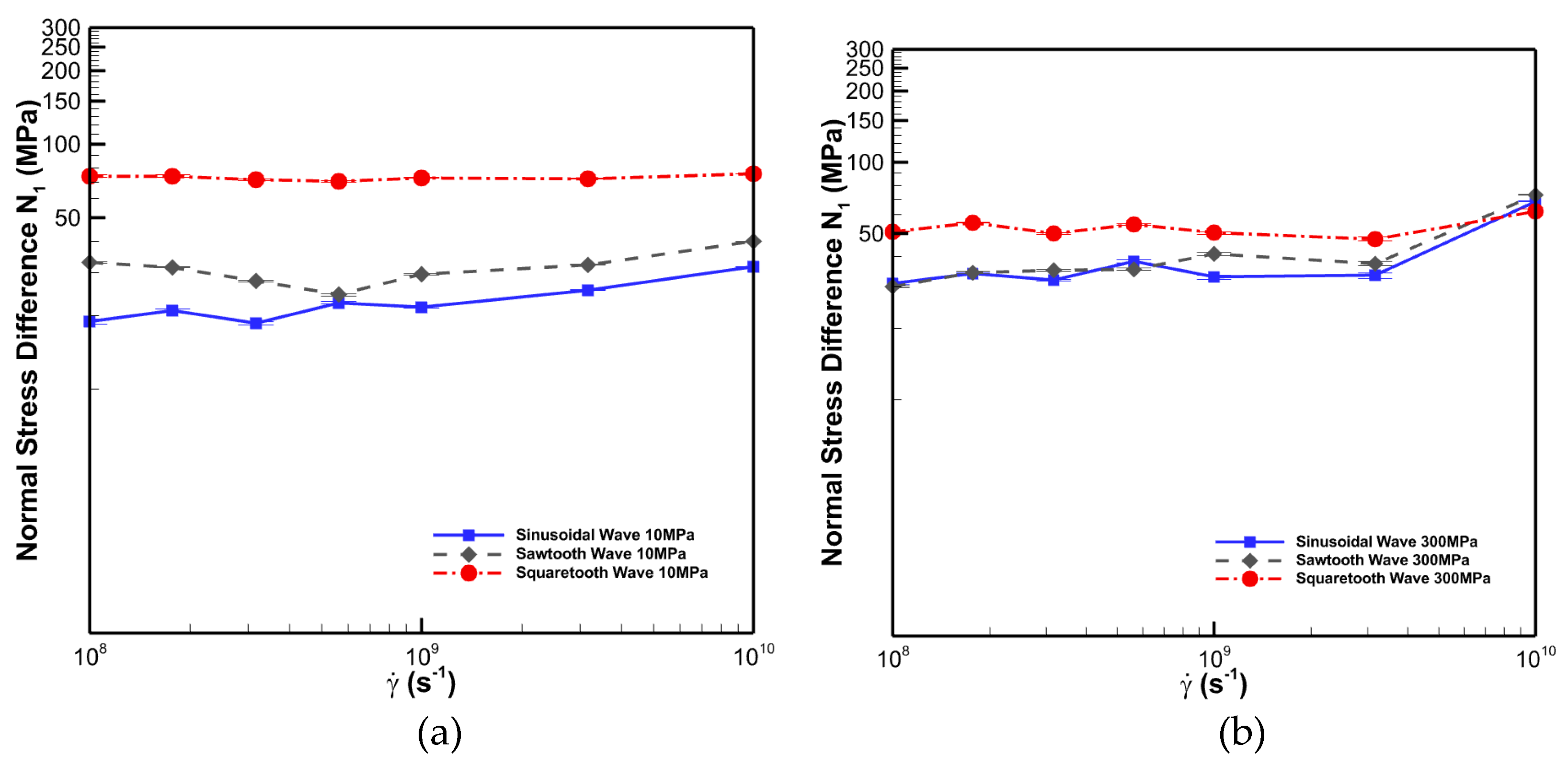
3.2.7. First Normal Stress Difference
Figure 12 (a–c) show the first normal stress difference for hexadecane for sinusoidal, sawtooth and squaretooth cases under 10 MPa and 300 MPa normal load, respectively.
The first normal stress difference (N1) refers to the difference in the normal stresses in the X and Z directions ()[24]. It seems the first normal stress difference does not change significantly with shear rate, especially for the squaretooth pattern case. Moreover, the first normal stress difference in the squaretooth case is significantly larger than in the other two. Also, the first normal stress difference in the sawtooth case is slightly larger than in the sinusoidal case. However, with the increase of normal load to 300 MPa, the difference in the N1 in all three cases becomes smaller and fluctuates with the shear rate.
4. Conclusions
In this study, we demonstrated that the geometric shape of surface texture significantly influences the rheological behaviour of the thin-film lubrication regime. We examined its rheological and structural properties under various loads and shear rates by simulating hexadecane confined between sinusoidal, sawtooth, and squaretooth patterned surfaces. This research is valuable for designing NEMS and other boundary condition applications related to lubrication.
Our findings reveal that at equilibrium, lower normal loads result in more ordered crystalline bridges, while higher normal loads disrupt these formations, creating small disordered groups. We observed slippage between layers at lower shear rates (less than ), making hexadecane behave similarly to solid lubricants like graphite due to the formation of crystalline bridges. At higher shear rates (greater than ), the lubricant remained in a liquid-like phase regardless of the normal load.
Under a low normal load (10 MPa) and low shear rate (less than ), the sawtooth patterned surface exhibited over 2 times higher viscosity than squaretooth patterned surfaces. This is because crystalline bridges are oriented perpendicular to the shearing direction in the sawtooth pattern case, leading to the highest friction and viscosity. However, crystalline bridges in the squaretooth pattern case all formed in the shearing direction, which promotes inter-layer slippage and contributes to the lowest viscosity. On the other hand, the crystalline bridges are stuck in small, randomly ordered domains in the sinusoidal pattern case, which leads to the viscosity between the sawtooth and squaretooth case.
Under a high normal load (300 MPa) and low shear rate (less than ), the high load disrupted the formation of crystalline bridges in sinusoidal and sawtooth patterns, breaking them into small groups. However, the parallel alignment of crystalline bridges persisted in the squaretooth case. Higher normal loads also reduced viscosity differences among the three patterns at lower shear rates but increased the viscosity for all.
Molecules in the grooves naturally align with the most extended face of the grooves and are perpendicular to the flow direction. The most significant first normal stress difference was consistently observed in the squaretooth case. However, as the normal load increased, the difference in the first normal stress difference between the sinusoidal and sawtooth cases diminished.
Author Contributions
Fankai Peng :Writing – review & editing, Writing – original draft, Visualization, Validation, Methodology, Investigation, Formal analysis, Data curation. Ahmad Jabbarzadeh: Writing – review & editing, Validation, Supervision, Software, Resources, Project administration, Methodology, Investigation, Conceptualization.
Funding
This research received no external funding.
Data Availability Statement
Not applicable.
Acknowledgments
The authors acknowledge the use of the National Computational Infrastructure (NCI), supported by the Australian Government and accessed through the NCI Merit Allocation Scheme and the Sydney Informatics Hub HPC Allocation Scheme, supported by the Deputy Vice-Chancellor (Research), University of Sydney. The authors also acknowledge using the high-performance computational facility (Artemis) at the University of Sydney's Sydney Informatics Hub.
Conflicts of Interest
The authors declare no conflicts of interest.
References
- Liu, H.; Bhushan, B. Nanotribological characterization of molecularly thick lubricant films for applications to MEMS/NEMS by AFM. Ultramicroscopy 2003, 97, 321–340. [CrossRef]
- Lee, K.K.; Bhushan, B.; Hansford, D. Nanotribological characterization of fluoropolymer thin films for biomedical micro/nanoelectromechanical system applications. J. Vac. Sci. Technol. A 2005, 23, 804–810. [CrossRef]
- Charitidis, C.A.; Koumoulos, E.P.; Dragatogiannis, D.A. Nanotribological Behavior of Carbon Based Thin Films: Friction and Lubricity Mechanisms at the Nanoscale. Lubricants 2013, 1, 22–47. [CrossRef]
- Arab, A.; Feng, Q. Reliability research on micro- and nano-electromechanical systems: a review. Int. J. Adv. Manuf. Technol. 2014, 74, 1679–1690. [CrossRef]
- Gundarneeya, T.P.; Vakharia, D. Performance analysis of journal bearing operating on nanolubricants with TiO2, CuO and Al2O3 nanoparticles as lubricant additives. Mater. Today: Proc. 2021, 45, 5624–5630. [CrossRef]
- Ramin, L.; Jabbarzadeh, A. Effect of Water on Structural and Frictional Properties of Self Assembled Monolayers. Langmuir 2013, 29, 13367–13378. [CrossRef]
- Jabbarzadeh, A. Friction anisotropy in confined alkanes: Linear and branched molecules. Tribol. Int. 2016, 97, 108–115. [CrossRef]
- Moshfegh, A.; Jabbarzadeh, A. Dissipative Particle Dynamics: Effects of Parameterization and Thermostating Schemes on Rheology. Soft Mater. 2015, 13, 106–117. [CrossRef]
- Chhowalla, M.; Amaratunga, G.A.J. Thin films of fullerene-like MoS2 nanoparticles with ultra-low friction and wear. Nature 2000, 407, 164–167. [CrossRef]
- Kogovšek J, Kalin M. Various MoS 2-, WS 2-and C-based micro-and nanoparticles in boundary lubrication. Tribology Letters. 2014 Mar;53:585-97.
- Du, R.; Zhang, A.; Du, Z.; Zhang, X. Molecular Dynamics Simulation on Thin-Film Lubrication of a Mixture of Three Alkanes. Materials 2020, 13, 3689. [CrossRef]
- Ghaednia, H.; Babaei, H.; Jackson, R.L.; Bozack, M.J.; Khodadadi, J.M. The effect of nanoparticles on thin film elasto-hydrodynamic lubrication. Appl. Phys. Lett. 2013, 103, 263111. [CrossRef]
- Rabaso, P.; Ville, F.; Dassenoy, F.; Diaby, M.; Afanasiev, P.; Cavoret, J.; Vacher, B.; Le Mogne, T. Boundary lubrication: Influence of the size and structure of inorganic fullerene-like MoS2 nanoparticles on friction and wear reduction. Wear 2014, 320, 161–178. [CrossRef]
- Zhao, P.; Zhou, X.; Yang, Y.; Wang, C.; Wang, C.; Liang, H.; Li, C.; Ren, H. Molecular dynamics simulation study of the effect of molecular structure of warm mix additive on lubricating properties. Constr. Build. Mater. 2023, 407. [CrossRef]
- Koplik J, Banavar JR, Willemsen JF. Molecular dynamics of fluid flow at solid surfaces. Physics of Fluids A: Fluid Dynamics. 1989 May 1;1(5):781-94.
- Hu, H.-W.; Carson, G.A.; Granick, S. Relaxation time of confined liquids under shear. Phys. Rev. Lett. 1991, 66, 2758–2761. [CrossRef]
- Jabbarzadeh, A.; Atkinson, J.; Tanner, R. The effect of branching on slip and rheological properties of lubricants in molecular dynamics simulation of Couette shear flow. Tribol. Int. 2002, 35, 35–46. [CrossRef]
- Jabbarzadeh, A.; Harrowell, P.; Tanner, R.I. Very Low Friction State of a Dodecane Film Confined between Mica Surfaces. Phys. Rev. Lett. 2005, 94, 126103. [CrossRef]
- Jabbarzadeh, A.; Harrowell, P.; Tanner, R.I. Crystal Bridge Formation Marks the Transition to Rigidity in a Thin Lubrication Film. Phys. Rev. Lett. 2006, 96, 206102. [CrossRef]
- Jabbarzadeh, A.; Harrowell, P.; Tanner, R.I. Crystal Bridges, Tetratic Order, and Elusive Equilibria: The Role of Structure in Lubrication Films. J. Phys. Chem. B 2007, 111, 11354–11365. [CrossRef]
- Yasuda, I.; Kobayashi, Y.; Endo, K.; Hayakawa, Y.; Fujiwara, K.; Yajima, K.; Arai, N.; Yasuoka, K. Combining Molecular Dynamics and Machine Learning to Analyze Shear Thinning for Alkane and Globular Lubricants in the Low Shear Regime. ACS Appl. Mater. Interfaces 2023, 15, 8567–8578. [CrossRef]
- Liu, D.; Li, H.; Huo, L.; Wang, K.; Sun, K.; Wei, J.; Chen, F. Molecular dynamics simulation of the lubricant conformation changes and energy transfer of the confined thin lubricant film. Chem. Eng. Sci. 2023, 270. [CrossRef]
- Krim, J.; Solina, D.H.; Chiarello, R. Nanotribology of a Kr monolayer: A quartz-crystal microbalance study of atomic-scale friction. Phys. Rev. Lett. 1991, 66, 181–184. [CrossRef]
- Jabbarzadeh, A.; Atkinson, J.D.; Tanner, R.I. Wall slip in the molecular dynamics simulation of thin films of hexadecane. J. Chem. Phys. 1999, 110, 2612–2620. [CrossRef]
- Ta, T.; Tieu, A.; Zhu, H.; Kosasih, B.; Zhu, Q.; Phan, H. The structural, tribological, and rheological dependency of thin hexadecane film confined between iron and iron oxide surfaces under sliding conditions. Tribol. Int. 2017, 113, 26–35. [CrossRef]
- Ta, T.D.; Tieu, A.K.; Tran, B.H. Influences of iron and iron oxides on ultra-thin carbon-based tribofilm lubrication. Tribol. Int. 2022, 173. [CrossRef]
- Bernardino, K.; Ribeiro, M.C.C. Confined ionic liquids films under shear: The importance of the chemical nature of the solid surface. J. Chem. Phys. 2023, 158, 094712. [CrossRef]
- Richardson S. On the no-slip boundary condition. Journal of Fluid Mechanics. 1973 Aug;59(4):707-19.
- Thompson, P.A.; Robbins, M.O. Shear flow near solids: Epitaxial order and flow boundary conditions. Phys. Rev. A 1990, 41, 6830–6837. [CrossRef]
- Jabbarzadeh, A.; Atkinson, J.D.; Tanner, R.I. Effect of the wall roughness on slip and rheological properties of hexadecane in molecular dynamics simulation of Couette shear flow between two sinusoidal walls. Phys. Rev. E 2000, 61, 690–699. [CrossRef]
- Hu, C.; Tang, D.; Lv, J.; Bai, M.; Zhang, X. Molecular dynamics simulation of frictional properties of Couette flow with striped superhydrophobic surfaces under different loads. Phys. Chem. Chem. Phys. 2019, 21, 17786–17791. [CrossRef]
- Jabbarzadeh, A. Effect of nano-patterning on oleophobic properties of a surface. Soft Matter 2013, 9, 11598–11608. [CrossRef]
- Jabbarzadeh, A.; Chen, X. Surface induced crystallization of polymeric nano-particles: effect of surface roughness. Faraday Discuss. 2017, 204, 307–330. [CrossRef]
- Pettas D, Karapetsas G, Dimakopoulos Y, Tsamopoulos J. Viscoelastic film flows over an inclined substrate with sinusoidal topography. I. Steady state. Physical Review Fluids. 2019 Aug 8;4(8):083303.
- Tlili, I. Impact of thermal conductivity on the thermophysical properties and rheological behavior of nanofluid and hybrid nanofluid. Math. Sci. 2021, 1–9. [CrossRef]
- Türkmen, I.; Yalamaç, E.; Keddam, M. Investigation of tribological behaviour and diffusion model of Fe2B layer formed by pack-boriding on SAE 1020 steel. Surf. Coatings Technol. 2019, 377, 124888. [CrossRef]
- Huang, Q.; Shi, X.; Xue, Y.; Zhang, K.; Wu, C. Recent progress on surface texturing and solid lubricants in tribology: Designs, properties, and mechanisms. Mater. Today Commun. 2023, 35. [CrossRef]
- Leong, J.Y.; Reddyhoff, T.; Sinha, S.K.; Holmes, A.S.; Spikes, H.A. Hydrodynamic Friction Reduction in a MAC–Hexadecane Lubricated MEMS Contact. Tribol. Lett. 2012, 49, 217–225. [CrossRef]
- Lapuerta, M.; Sánchez-Valdepeñas, J.; Sukjit, E. Effect of ambient humidity and hygroscopy on the lubricity of diesel fuels. Wear 2014, 309, 200–207. [CrossRef]
- Cafolla, C.; Voïtchovsky, K. Impact of water on the lubricating properties of hexadecane at the nanoscale. Nanoscale 2020, 12, 14504–14513. [CrossRef]
- Wang, K.; Li, J.; Li, J.; Wu, C.; Yi, S.; Liu, Y.; Luo, J. Hexadecane-containing sandwich structure based triboelectric nanogenerator with remarkable performance enhancement. Nano Energy 2021, 87, 106198. [CrossRef]
- Iizuka, M.; Mizukami, M.; Kurihara, K. A Macro and Nanoconfined Tribological Study of Linear and Branched Molecules. Tribol. Lett. 2023, 71, 1–10. [CrossRef]
- Ryckaert, J.-P.; Bellemans, A. Molecular dynamics of liquid n-butane near its boiling point. Chem. Phys. Lett. 1975, 30, 123–125. [CrossRef]
- Jabbarzadeh, A. The Origins of Enhanced and Retarded Crystallization in Nanocomposite Polymers. Nanomaterials 2019, 9, 1472. [CrossRef]
- Jabbarzadeh, A. Effect of molecular branching and surface wettability on solid-liquid surface tension and line-tension of liquid alkane surface nanodroplets. J. Colloid Interface Sci. 2024, 666, 355–370. [CrossRef]
- Jabbarzadeh, A.; Atkinson, J.D.; Tanner, R.I. Effect of Molecular Shape on Rheological Properties in Molecular Dynamics Simulation of Star, H, Comb, and Linear Polymer Melts. Macromolecules 2003, 36, 5020–5031. [CrossRef]
- Chynoweth, S.; Michopoulos, Y. An improved potential model for n-hexadecane molecular dynamics simulations under extreme conditions. Mol. Phys. 1994, 81, 133–141. [CrossRef]
- van der Ploeg, P.; Berendsen, H.J.C. Molecular dynamics simulation of a bilayer membrane. J. Chem. Phys. 1982, 76, 3271–3276. [CrossRef]
- Lees, A.W.; Edwards, S.F. The computer study of transport processes under extreme conditions. J. Phys. C: Solid State Phys. 1972, 5, 1921–1928. [CrossRef]
- Evans D, Morris GP. Statistical mechanics of nonequilibrium fluids academic press. San Diego. 1990.
- Daivis PJ, Evans DJ, Morriss GP. Computer simulation study of the comparative rheology of branched and linear alkanes. The Journal of Chemical Physics. 1992 Jul 1;97(1):616-27.
- Evans, D.J.; Morriss, O. Non-Newtonian molecular dynamics. Comput. Phys. Rep. 1984, 1, 297–343. [CrossRef]
- Georges JM, Millot S, Loubet JL, Tonck A, Mazuyer D. Surface roughness and squeezed films at molecular level. In Tribology Series 1993 Jan 1 (Vol. 25, pp. 443-452). Elsevier.
- Jabbarzadeh, A.; Atkinson, J.; Tanner, R. A parallel algorithm for molecular dynamics simulation of branched molecules. Comput. Phys. Commun. 2003, 150, 65–84. [CrossRef]
- Jabbarzadeh, A.; Atkinson, J.; Tanner, R. Parallel simulation of shear flow of polymers between structured walls by molecular dynamics simulation on PVM. Comput. Phys. Commun. 1997, 107, 123–136. [CrossRef]
- Klein T, Yan S, Cui J, Magee JW, Kroenlein K, Rausch MH, Koller TM, Fröba AP. Liquid viscosity and surface tension of n-hexane, n-octane, n-decane, and n-hexadecane up to 573 K by surface light scattering. Journal of Chemical & Engineering Data. 2019 Aug 16;64(9):4116-31.
Figure 1.
(a) Sinusoidal, (b) sawtooth and (c) squaretooth patterned wall.
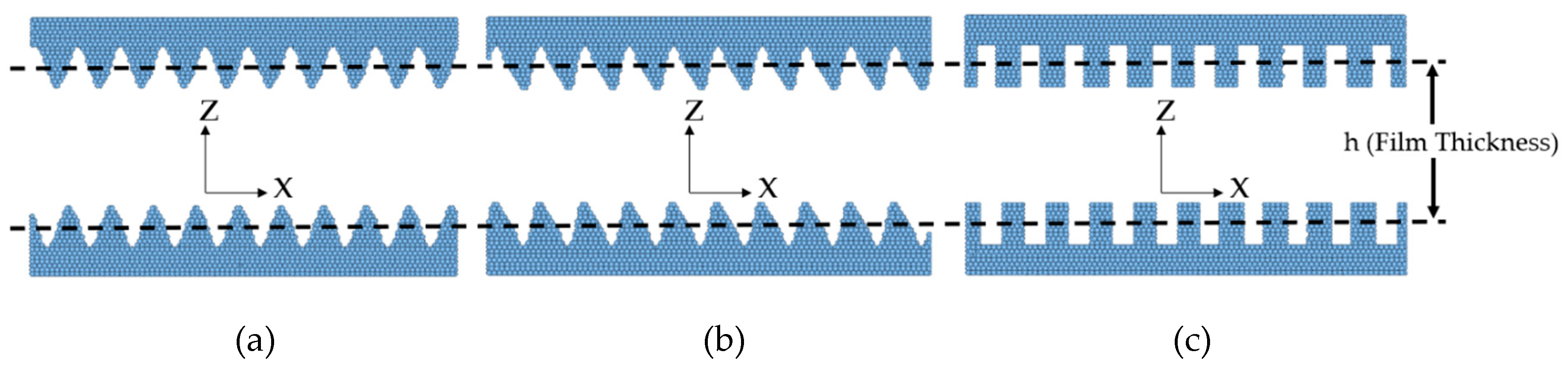
Figure 2.
Three stages of simulation include loading, equilibrium, and sliding stages. The snapshot of the bulk system is taken from the bulk state obtained from “sllod” [52] flow simulation. The snapshots of the loading stage are taken from the first state of Couette flow simulations. The snapshots of the equilibrium stage are taken from the state under 10 MPa normal load without applying shear rates after equilibrating for 37.7 ns. The snapshots of the shear situations stage are taken from the state at shear rate under 10 MPa normal load after 18.8 ns.
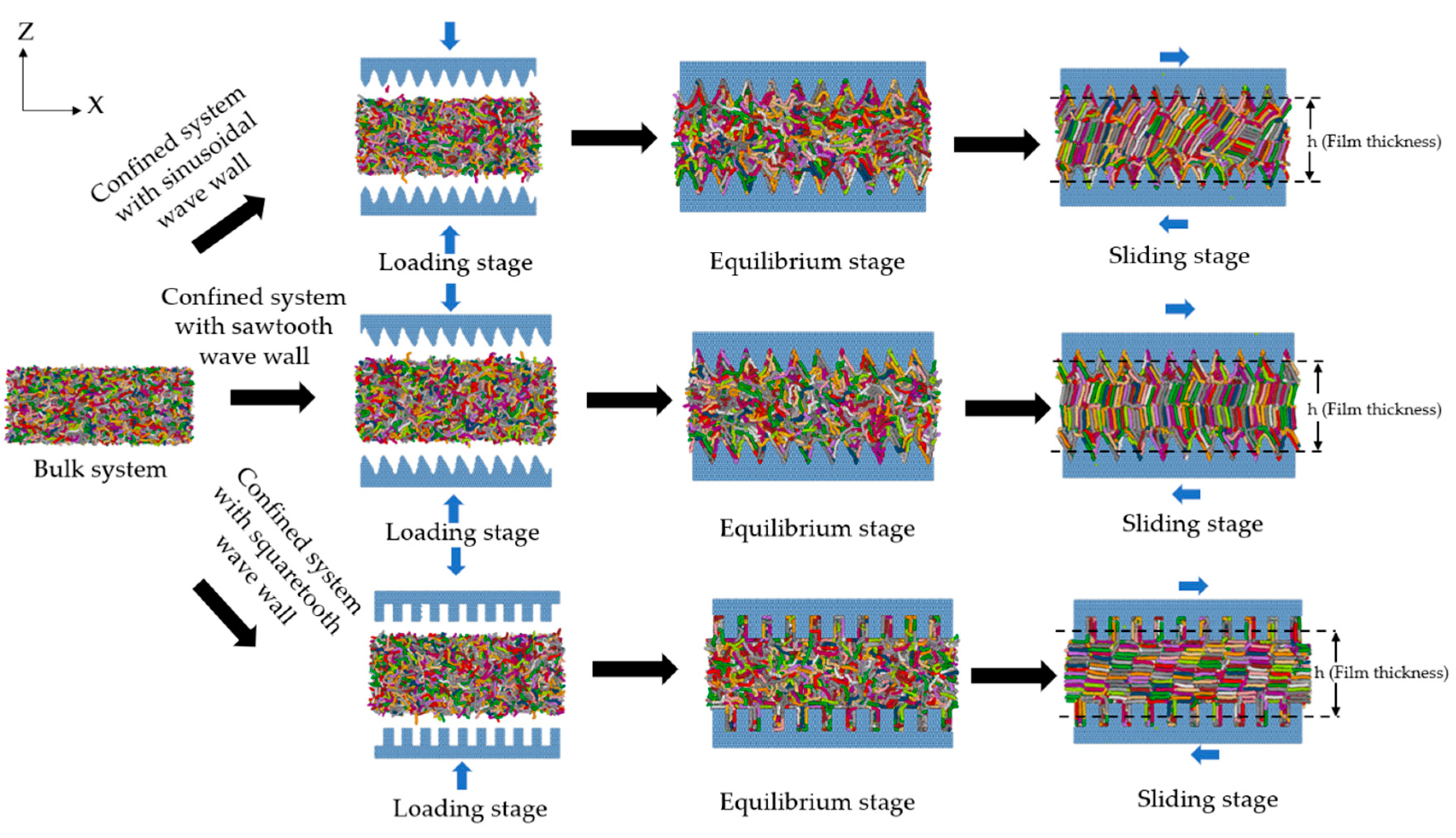
Figure 3.
Snapshots of the equilibrated lubricant molecular structure for sinusoidal, sawtooth and squaretooth patterned surfaces under the 10 (top row) and 300 MPa (bottom row) load with the corresponding
Figure 3.
Snapshots of the equilibrated lubricant molecular structure for sinusoidal, sawtooth and squaretooth patterned surfaces under the 10 (top row) and 300 MPa (bottom row) load with the corresponding
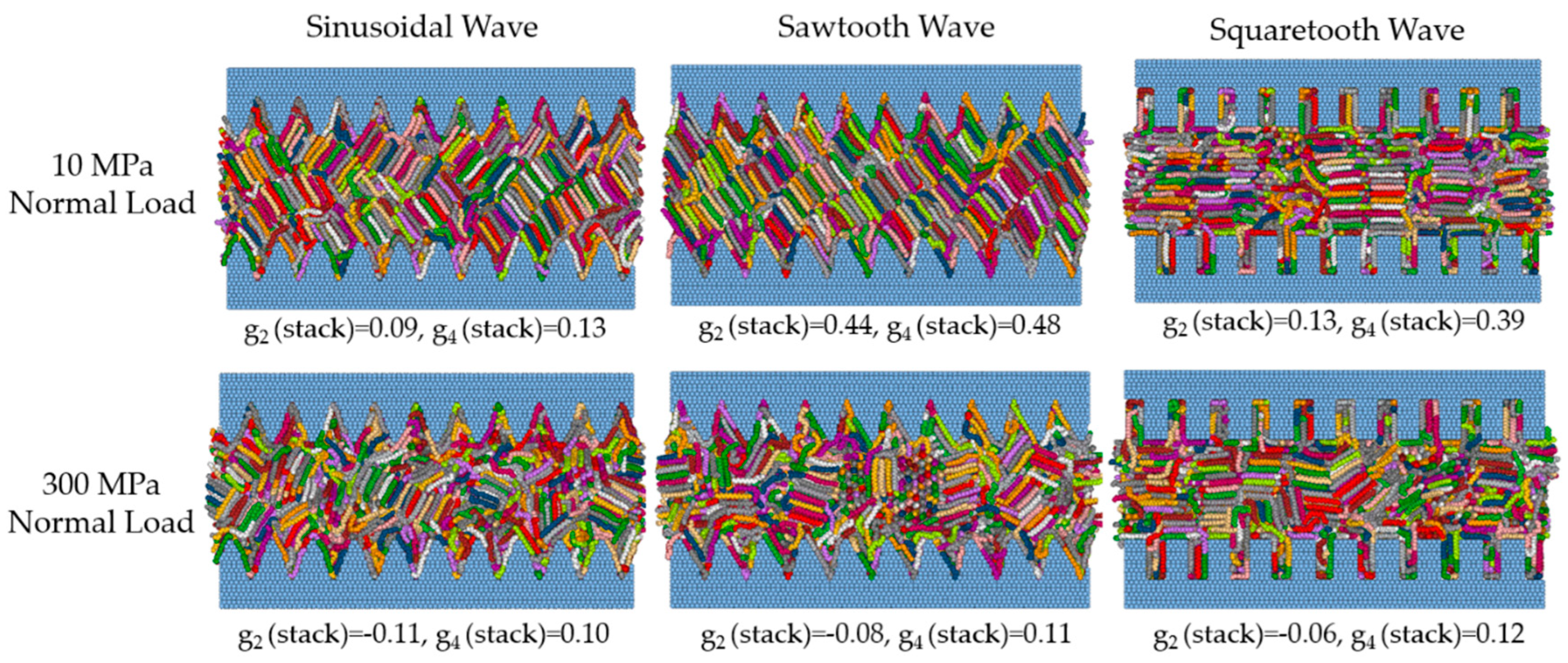
Figure 4.
Temperature (top row), pressure (second row), and density (third row) contours for sinusoidal (left column), sawtooth (middle column), and squaretooth (right column) wave patterned walls at a shear rate of
Figure 4.
Temperature (top row), pressure (second row), and density (third row) contours for sinusoidal (left column), sawtooth (middle column), and squaretooth (right column) wave patterned walls at a shear rate of
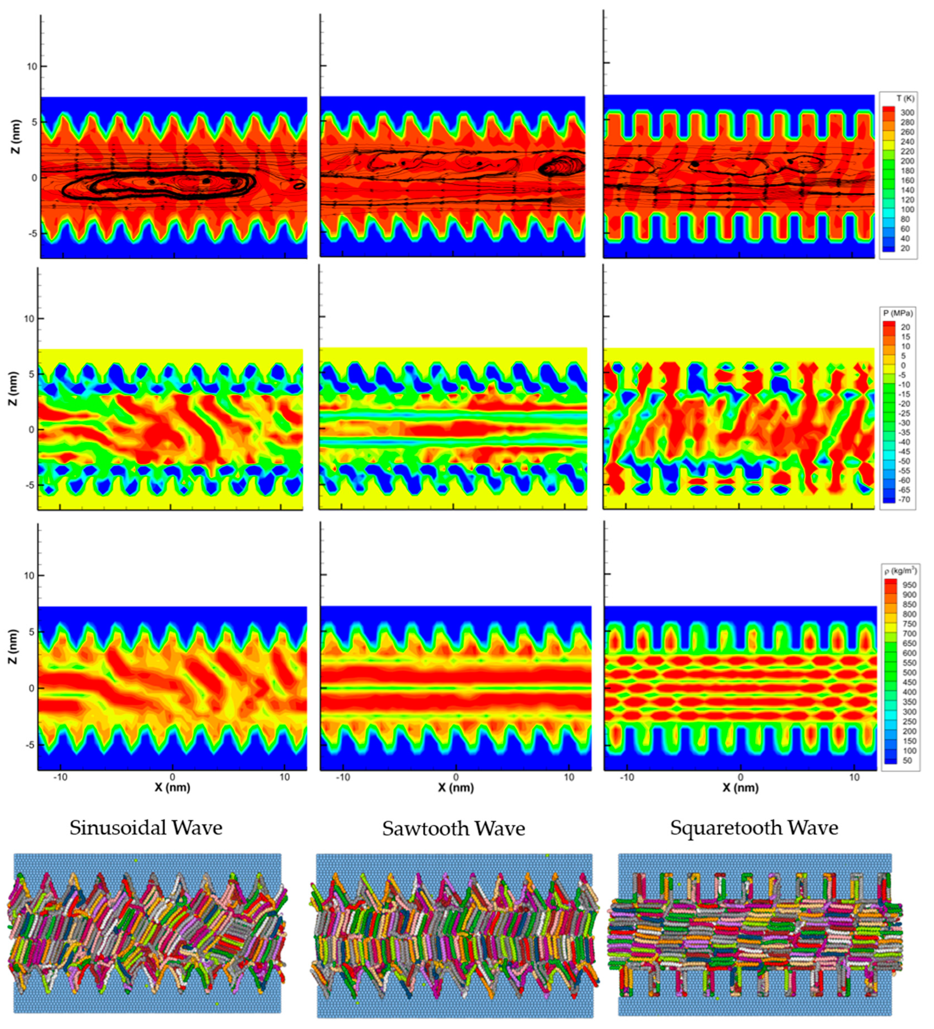
Figure 5.
The density (top panels) and normalised velocity (bottom panels) profiles for films under 10 MPa normal load undergoing shear at 108 s-1(left column) and 1010 s-1 (right column). The results are shown for the three different surfaces.
Figure 5.
The density (top panels) and normalised velocity (bottom panels) profiles for films under 10 MPa normal load undergoing shear at 108 s-1(left column) and 1010 s-1 (right column). The results are shown for the three different surfaces.
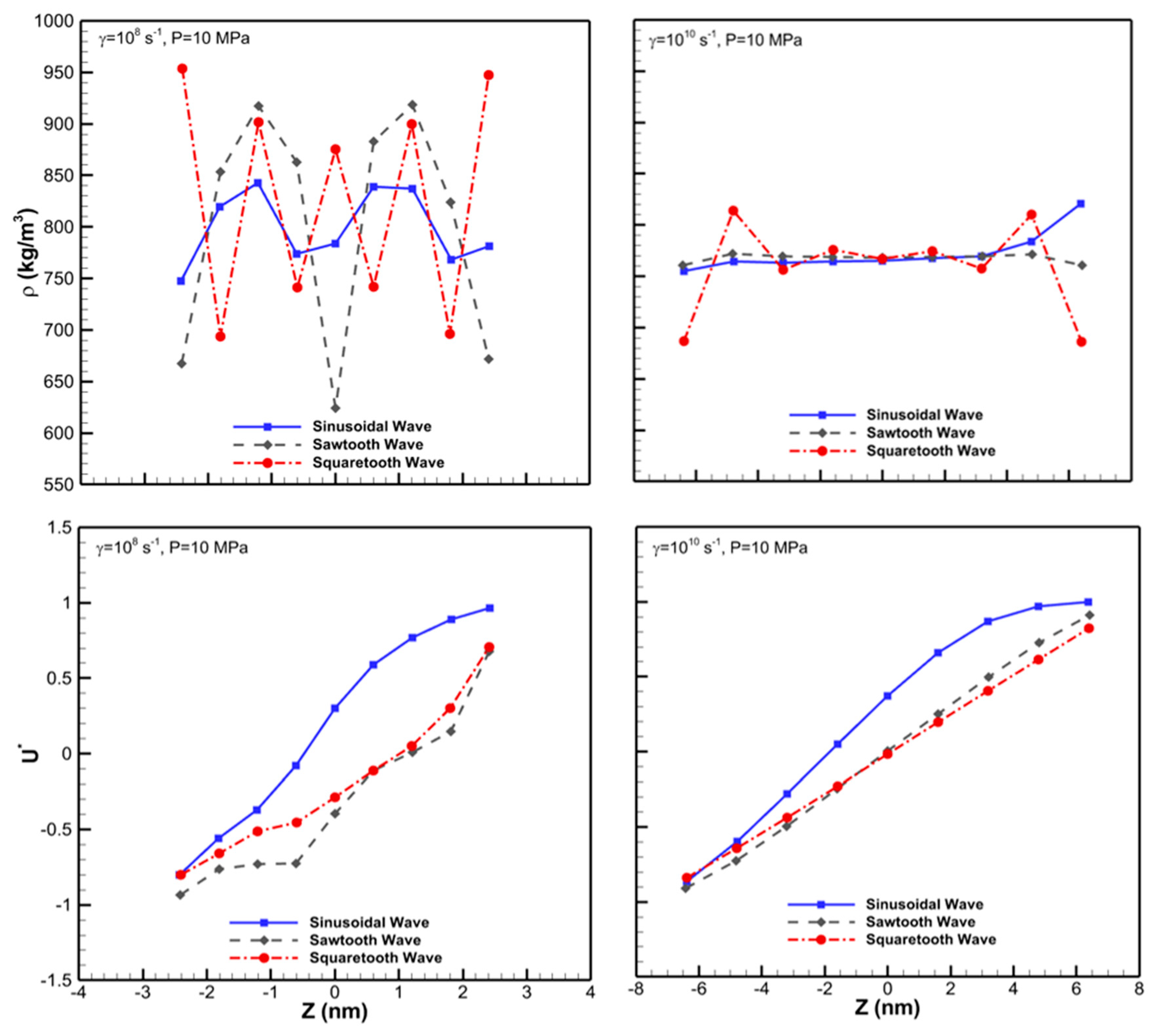
Figure 6.
Snapshots for sinusoidal, sawtooth and squaretooth patterned wall cases at
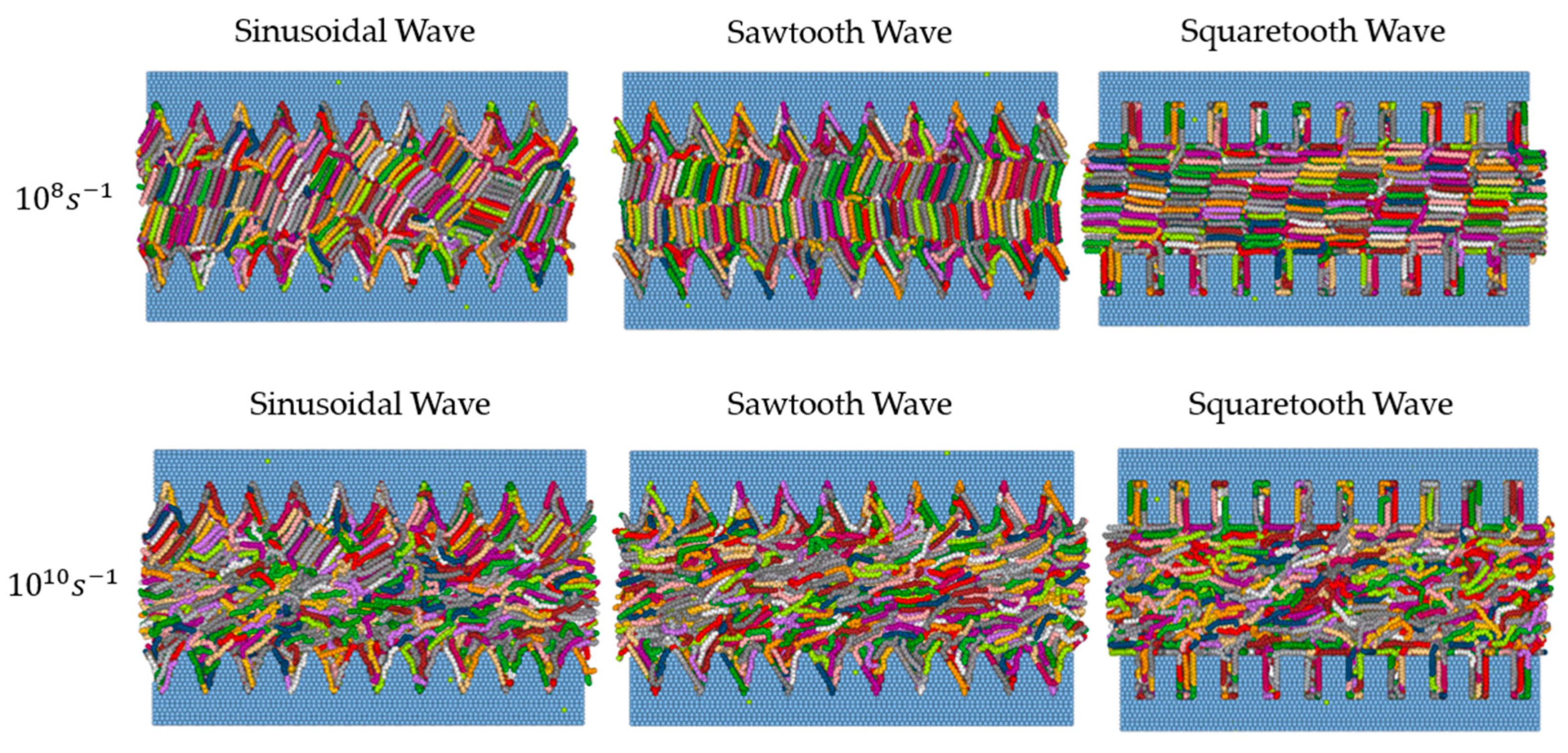
Figure 7.
Snapshots for sinusoidal, sawtooth and squaretooth patterned wall (left to right) cases at
Figure 7.
Snapshots for sinusoidal, sawtooth and squaretooth patterned wall (left to right) cases at
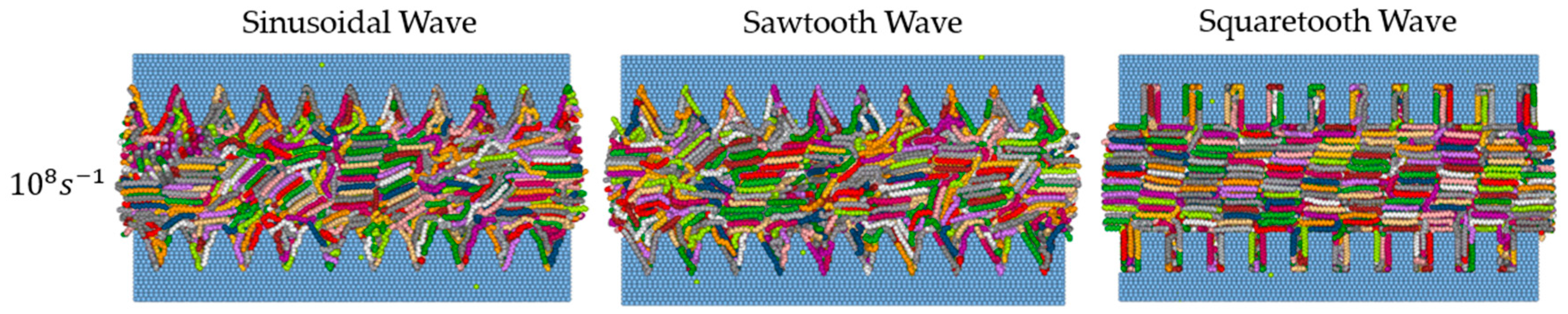
Figure 8.
Snapshots for different patterned wall cases at
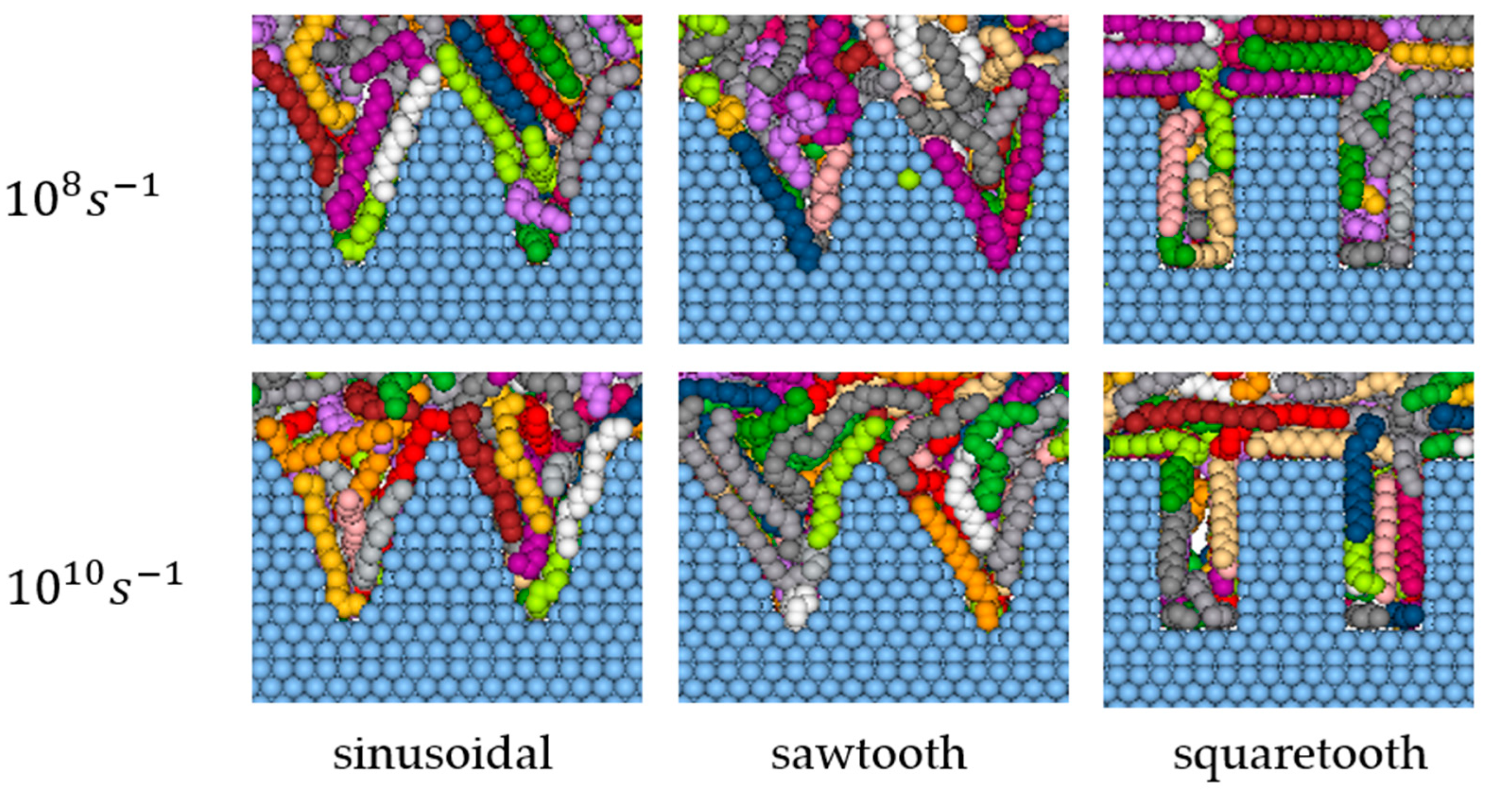
Figure 9.
Film thickness (h), density (ρ), g2, g4, and shear stress σxz as a function of time for hexadecane film confined at P=10 MPa and at a shear rate of 108 s-1for three different wall patterns of sinusoidal, sawtooth and squaretooth.
Figure 9.
Film thickness (h), density (ρ), g2, g4, and shear stress σxz as a function of time for hexadecane film confined at P=10 MPa and at a shear rate of 108 s-1for three different wall patterns of sinusoidal, sawtooth and squaretooth.
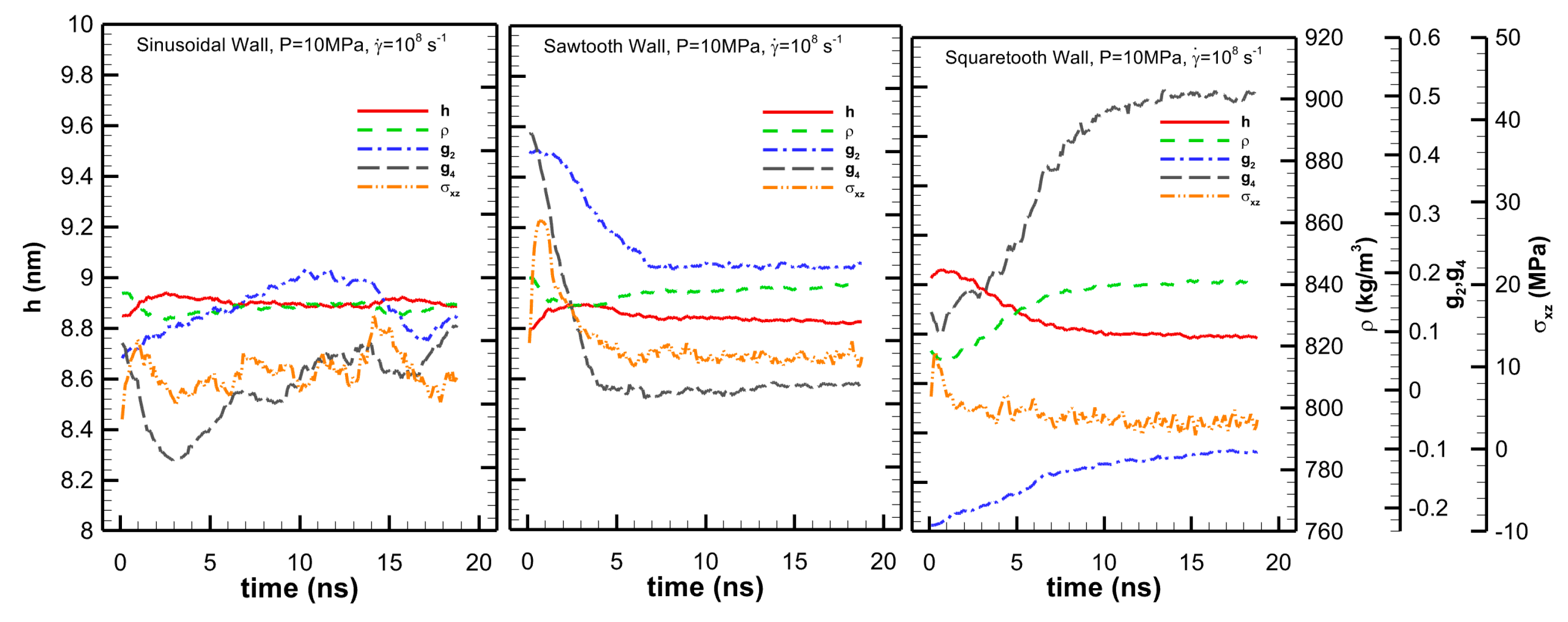
Figure 10.
The shear viscosity (top panels) and film thickness (bottom panels) for different patterned wall cases under 10 MPa (left panels), and 300 MPa (right panels). The results are shown for sinusoidal, sawtooth, and sqauretooth surfaces.
Figure 10.
The shear viscosity (top panels) and film thickness (bottom panels) for different patterned wall cases under 10 MPa (left panels), and 300 MPa (right panels). The results are shown for sinusoidal, sawtooth, and sqauretooth surfaces.
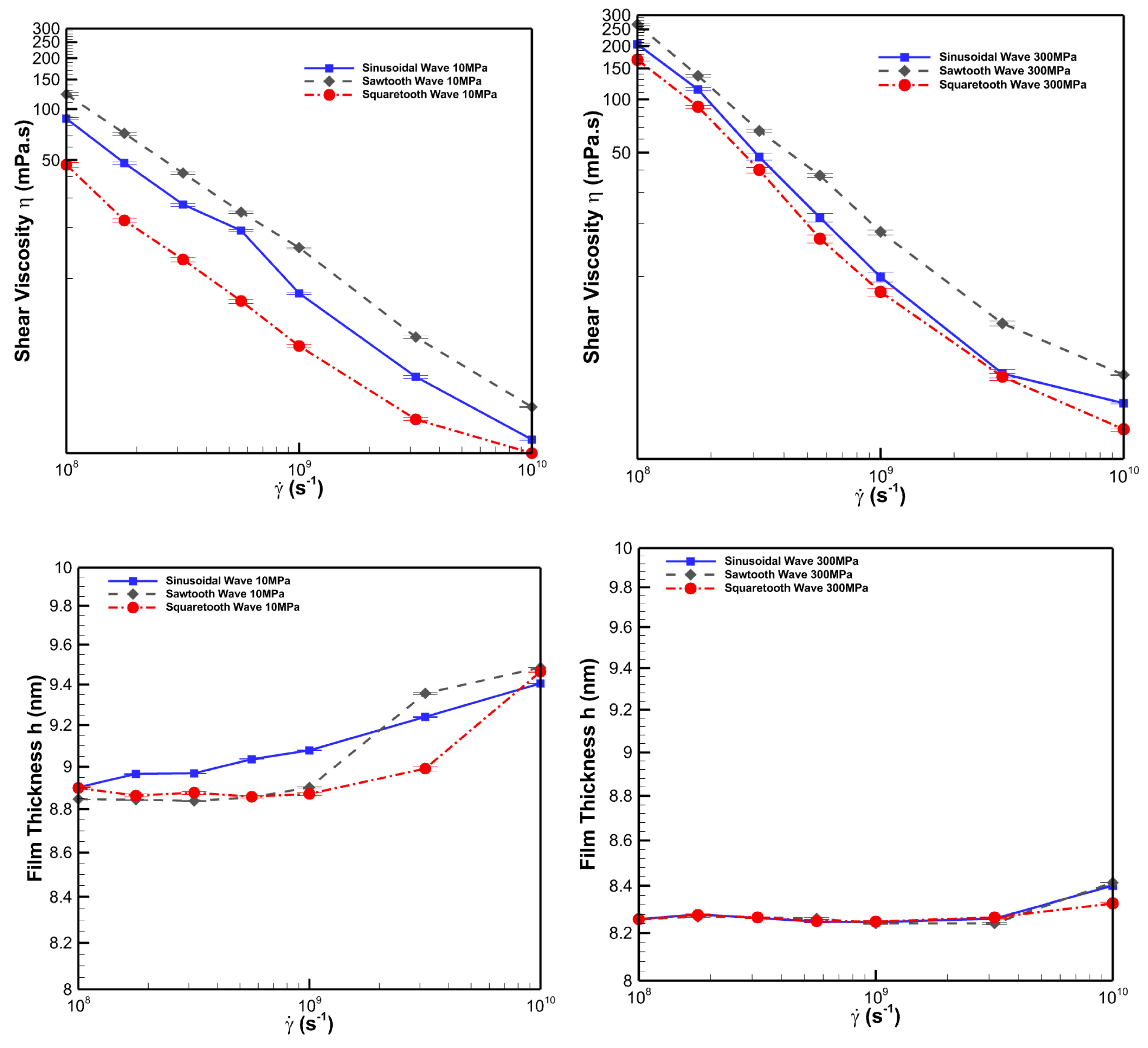
Figure 11.
Time evolution of
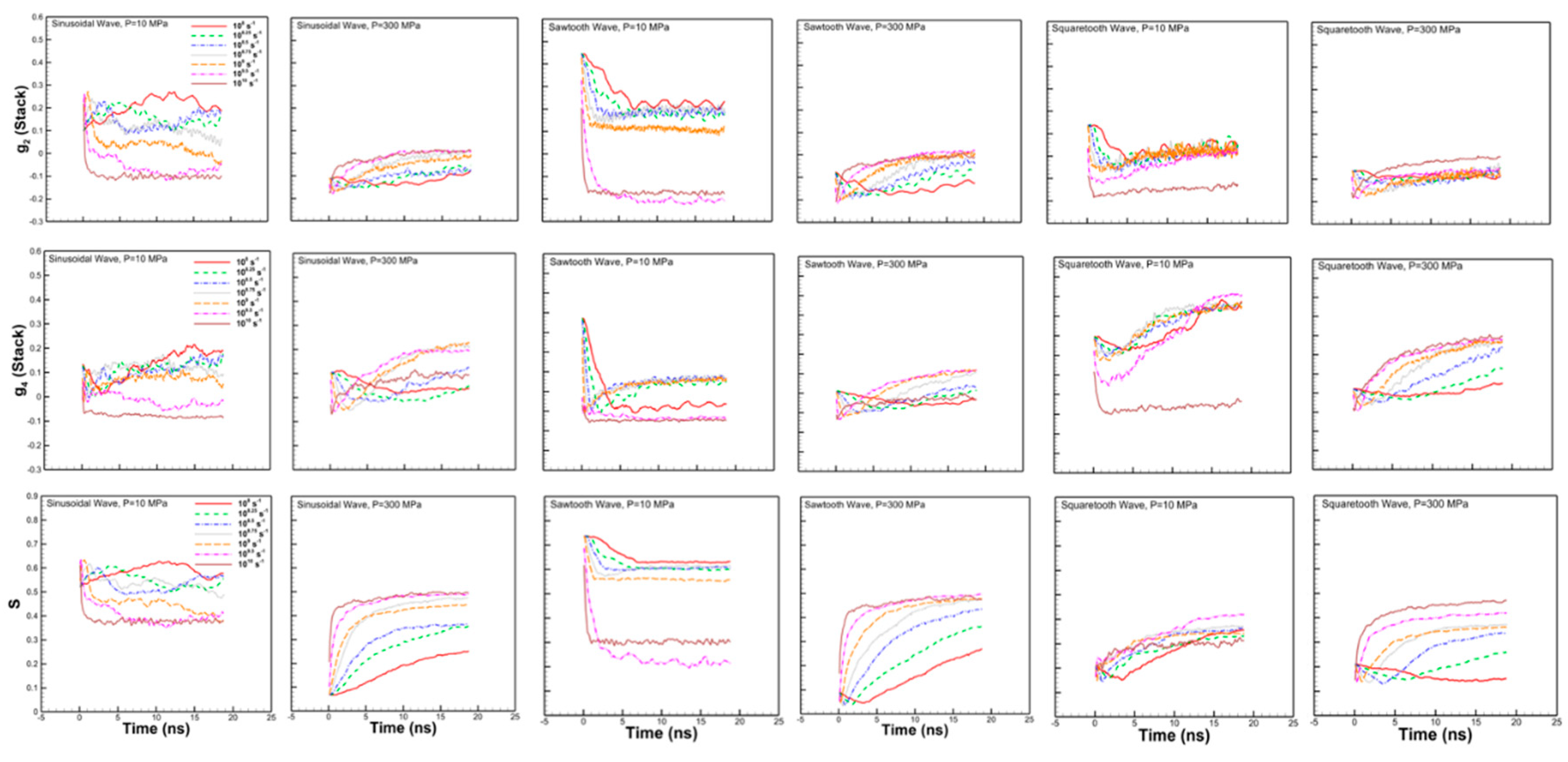
Figure 12.
The first normal stress difference for all cases under (a) 10 MPa, (b) 300 MPa normal load
Figure 12.
The first normal stress difference for all cases under (a) 10 MPa, (b) 300 MPa normal load
Disclaimer/Publisher’s Note: The statements, opinions and data contained in all publications are solely those of the individual author(s) and contributor(s) and not of MDPI and/or the editor(s). MDPI and/or the editor(s) disclaim responsibility for any injury to people or property resulting from any ideas, methods, instructions or products referred to in the content. |
© 2024 by the authors. Licensee MDPI, Basel, Switzerland. This article is an open access article distributed under the terms and conditions of the Creative Commons Attribution (CC BY) license (http://creativecommons.org/licenses/by/4.0/).
Copyright: This open access article is published under a Creative Commons CC BY 4.0 license, which permit the free download, distribution, and reuse, provided that the author and preprint are cited in any reuse.


