
Submitted:
06 December 2024
Posted:
10 December 2024
You are already at the latest version
Abstract
Background/Objectives: Accurate detection of microcalcifications in mammograms is critical for the early detection of breast cancer. However, variability between different manufacturers is significant, particularly with digital breast tomosynthesis (DBT). Manufacturers have many design differences, including sweep angles, detector types, reconstruction techniques, filters, and focal spot size. This study describes developing a novel phantom model based on crystallizations to standardize microcalcification detection in DBT, aiming to create consistency in the evaluation, which can lead to inconsistent interpretations and patient management. Methods: We created a novel phantom model that simulates different types of breast tissue density with calcifications. Further, these crystalline-grown phantoms can more accurately represent microcalcification’s physiological shapes and compositions than other available phantoms for calcifications and can be evaluated on different systems. Microcalcification patterns were generated using evaporation of sodium chloride, transplantation of calcium carbonate crystals, and/or injection of hydroxyapatite. These patterns were embedded in multiple layers within the wax to simulate various depths and distributions of calcifications with the ability to generate a large variety of patterns. Results: Tomosynthesis imaging revealed that phantoms utilizing calcium carbonate crystals showed demonstrable visualization differences between the 3D DBT reconstructions and the magnification/2D view, illustrating the model's value. The phantom was able to highlight changes in contrast and resolution, which is crucial for accurate microcalcification evaluation. Conclusions: Based on crystalline growth, this phantom model offers an important new standardized target for evaluating DBT systems. By promoting standardization, especially through the development of advanced breast calcification phantoms, this work and design aims to contribute to improving earlier and more accurate breast cancer detection.
Keywords:
Keywords Digital Breast Tomosynthesis (DBT)
; Microcalcifications
; Phantom Models
; Standardization
; Diagnostic Accuracy
1. Introduction
A critical design objective of mammography scanners for breast radiologists is that the technology should provide them confidence in accurate diagnostic evaluation of calcifications, a goal that can be achieved by better validation of calcification detection during manufacturing. Correct identification of calcifications is essential for the early detection of breast cancer and ensures that patients receive accurate and reliable diagnostic evaluations. In addition, 3D-digital breast tomosynthesis (DBT) is increasingly used for breast imaging; however, there is a notable trade-off in the visibility of microcalcifications when DBT is performed alone [1]. For this reason, DBT is used in combination with conventional 2D full-field digital mammography (FFDM), which can result in greater radiation doses to the patient. In this work, we use a novel set of phantom designs that add to the arsenal of potential tools that can provide accurate and reliable assessments of calcifications. Our design replicates clinical scenarios that involve microcalcifications, can potentially assist in developing better microcalcification evaluation, and is compatible with multiple vendors despite the technical differences in mammography equipment. The development of these phantoms will provide manufacturers with increased opportunity to move toward more unified targets for design.
Calcifications, often the earliest indicator of ductal carcinoma in situ (DCIS) and early-stage invasive breast cancer, are detected in screening mammograms and serve as a critical diagnostic marker for breast cancer [2]. In many cases, especially for younger women with dense breast tissue, detecting these calcifications is challenging, as dense tissue can obscure minor abnormalities. Mammographic findings classified as BI-RADS category 0 on screening examination, as seen in Figure 1, prompt a recall for further evaluation, which may include additional imaging, ultrasound, and potentially invasive procedures like fine needle aspiration (FNA) or core needle biopsy (CNB) [3].
While mammography has a high sensitivity for detecting calcifications, its specificity is limited, leading to a significant number of false-positive results [4]. This often subjects women to unnecessary follow-up tests, causing additional emotional and physical burdens. Despite these challenges, mammography remains a critical tool in early breast cancer detection, with around 56,500 new DCIS cases and over 310,000 invasive breast cancer cases expected in 2024 [21]. Variability in sensitivity and specificity for calcifications on mammography across imaging centers highlights the need for improved methods of detection.
Our study aims to address this need by developing a standardized phantom model that mimics the unique properties of human breast tissue, which contains various abnormalities, including microcalcifications. Unlike conventional phantoms, our design leverages crystalline growth methods to create a more accurate representation of the complex shapes and compositions of microcalcifications. Our goal is to enhance diagnostic consistency across centers and optimize the recall rate.
1.1. Physiological and Diagnostic Features of Cancer Subtypes Targeted for Improved Visualization Under DBT
One of the earliest signs of some types of breast cancer is microcalcifications, which are commonly associated with DCIS [2], and thus, microcalcifications are one major imaging feature assessed in breast mammography. Different breast pathologies can give rise to different patterns of calcifications on mammography. Examples of benign breast pathology include simple cysts, fat necrosis, fibroadenomas, and ductal ectasia. Benign calcifications can appear as eggshell-like, popcorn-like, and large rod-like calcifications (5,19). The morphologic appearance of microcalcifications on mammography can help determine the likelihood of breast malignancy (Figure 2). The complexity of visualizing and diagnosing breast calcifications highlights the need for standardized mammography technologies, which would enable radiologists to achieve greater diagnostic accuracy. Variations in the ability of mammography systems to visualize microcalcifications can lead to inconsistent interpretations and patient management. Providing physicians with consistently high-quality images across technologies, vendors, and institutions is crucial for accurate diagnoses, efficient workflows, and optimal patient care.
1.2. Ensuring Compliance and Advancing Technology in Breast Tomosynthesis
Obtaining high-quality images of breast calcifications is a critical responsibility of a mammography center and the healthcare workers at that institution, and thus, is of crucial importance to mammography scanner manufacturers. Further, the provision of high-quality patient care and safety standards requires that mammography systems comply with rigorous guidelines. These constraints typically cover a range of multifactorial competing objectives that include image quality, radiation dose, equipment performance, and quality control procedures. Thus, compliance with standards is intended to increase the potential for consistency in breast screening exams [6]. Ensuring that mammography machines comply with established guidelines, such as those specified by the FDA, imposes an immense burden and responsibility on manufacturers, and all manufacturers invest significant resources for testing, evaluation of compliance, and documentation throughout the development of medical scanners. Detecting and characterizing microcalcifications is just one among many design goals in mammography imaging and is an element that can easily be overlooked. Incorporating our advanced phantom model in mammography design promises to significantly improve the uniformity in interpreting calcifications. Standardization is achieved by using a real target, such as a phantom that mimics the conditions radiologists encounter in actual clinical situations, as discussed in our work. This will empower healthcare professionals to assess calcifications more consistently and help reduce the variation in patient recall rates across imaging centers. This approach will streamline patient care, alleviate patient anxiety, and optimize resource use by minimizing unnecessary recalls and ensuring patients are only called back when necessary. Ultimately, our phantom design aims to enhance diagnostic accuracy, leading to more effective and patient-centered breast cancer screening protocols. Test phantoms, such as the sets we propose, will enhance design processes and increase confidence in imaging the types of calcifications seen both during the training of mammographers and in real-world conditions encountered by radiologists.
1.3. Design Considerations and Trade-offs in Breast Tomosynthesis Technology
Breast tomosynthesis technology construction depends on various intricate design factors, including focal size, exposure levels, motion type (i.e., continuous or stepped), sweep angle, detector choice, and reconstruction methods, all representing trade-offs that manufacturers must manage [7]. Resolution and contrast are distinct aspects of imaging; contrast often correlates with the X-ray exposure and dose received by the breast, while resolution is influenced by patient movement, sensor design, and the number and angle of the tomosynthesis machine’s sweep, among other factors [7].
1.4. Sweep Angle Considerations in DBT: How Sweep Angle Impacts Affect the Resolution and Dose, Highlighting Key Differences Between Vendors for Breast Calcifications
One of the key differences between vendors is the angle of sweep in DBT systems, as shown in Figure 3. Changes in the sweep angle affect the visualization of objects and increase the number of ‘shots’, all while attempting to remain dose-neutral (regarding tradeoffs between 2D-FFPM and DBT) [8]. Wider angles (with more exposure and/or shots – e.g., 50 degrees) can produce less in-plane resolution over a focused area but provide greater resolution over a specific area when combined with narrower angles. Thus, with the dose control assumption for less ‘shots’ and/or less exposure, narrow-angle DBT (for example, 15 degrees) systems produce a higher in-plane spatial resolution, making them theoretically better at visualizing small objects like microcalcifications. Additionally, narrow-angle DBT has shorter scan times, resulting in sharper images with fewer motion artifacts. Conversely, wide-angle DBT systems have a better out-of-plane spatial resolution, which helps differentiate findings from overlapping tissue, making them better for visualizing masses and architectural distortions [9]. Some phantom studies support the use of narrow-angle DBT for evaluating calcifications, with some suggesting it detects small, subtle calcifications better than wider-angle DBT [20]. However, the choice of sweep angle is just one-factor influencing microcalcification visualization. Other key factors include the materials used in the imaging system (e.g., filtration and focal spot), detector and system electronics, reconstruction methodology, and the ability to provide magnification and spot imaging. Modifications to these factors, beyond the sweep angle, also affect microcalcification detection. Without thorough phantom studies or clinical trials, the most effective systems for evaluating calcifications remain uncertain. These factors, including materials, detectors, and reconstruction methods, are explored further in the following sections.
1.5. Detector Differences and Similarities Between Manufacturers
Detector design varies among DBT manufacturers, as shown in Table 1. For instance, both cesium iodide (CsI) with amorphous silicon (a-Si) and amorphous selenium (a-Se) present distinct advantages. CsI with a-Si provides higher detective quantum efficiency (DQE), minimal light loss, and a wide dynamic range, making it versatile for different imaging conditions [18]. In contrast, a-Se allows for direct conversion, resulting in sharper images and higher spatial resolution, which is crucial for detecting small calcifications and fine details. Practical considerations, such as cost, availability, and existing infrastructure, also influence the choice of detector technology.
1.6. Reconstruction of Mammographic Images: Complexity for Microcalcifications in DBT
Addressing the reconstruction of mammographic microcalcifications through tomosynthesis presents an array of design challenges that require innovative solutions to achieve optimal outcomes. Manufacturers are tasked with employing diverse correction methods to manage noise levels, ensure edge quality, maintain microcalcification visibility, and address out-of-slice artifacts. For instance, Abdurahman et al. utilize transformations for each projection that can be combined from different slice values, although this may impact integrated spatial resolution [10]. This reconstruction design can challenge capturing higher spatial resolution structures such as calcifications. However, reconstruction methods operated on slices can be generated using a statistical artifact reduction (SAR) method followed by inversion modulation transfer function (MTF) and applying empirical spectral and spatial thickness filters, providing promising avenues for advancement to improve complex reconstruction. Furthermore, techniques to manage out-of-slice artifacts are critical for enhancing image quality and diagnostic accuracy. These artifacts, characterized by the blurring or ghosting of structures, not in the plane of interest but appearing in the reconstructed slice, require careful handling. Approaches like super-resolution and regression of structures modeling can enhance performance, with each manufacturer employing various methods to address reconstruction quality. Overall, the ongoing innovative efforts and promising methodologies being explored in this field encourage confidence in the future of mammographic microcalcification reconstruction through tomosynthesis. However, ongoing innovations vary greatly between vendors which can lead to standardization challenges if not given appropriate targets that can be designed against, such as phantoms.
1.7. Filters Used in Mammographic DBT
In DBT, various filters optimize image quality and minimize radiation dose, and different vendors implement them in distinct ways. These filters include rhodium (Rh), aluminum (Al), silver (Ag), and molybdenum (Mo). Rh is often used because it effectively filters out lower-energy X-rays, helping to reduce patient dose while maintaining image quality and improving contrast, especially in thicker or denser breasts. Al is another less expensive filter that balances image quality and radiation dose and is one of the primary materials used in current mammography scanners. Additionally, Ag can sometimes be utilized in systems to enhance contrast and improve visualization of breast tissue, while Mo filters, although less common, are also used [11]. In X-ray systems, the focusing cup concentrates the electron beam toward the focal spot on the anode. The focusing cup is a negatively charged depression on the cathode side of the X-ray tube and is typically made of materials chosen for their ability to withstand high temperatures and effectively focus the electron beam. In the focusing cup, mammography device vendors sometimes have one or two filaments that produce focal spots with nominal sizes of 0.3 mm and 0.1 mm. Focal spots of 0.1 mm are used for magnification mammography, achieving high spatial resolution by minimizing geometric blurring [12].
1.8. Magnification/Spot Compression Techniques for Improved Calcification and for Overlapping Tissue Visualization of the Breast Tissue
When indeterminate calcifications are suspected on the 3D DBT or FFDM, further diagnostic imaging could be obtained with magnification views to provide a more comprehensive evaluation of these lesions. If the DBT/FFDM images reveal any concerns after the patient has left following their screening exam, the patient may be asked to return to the breast care center for additional images with magnification. This causes anxiety and stress for some patients as they await a more definitive result. Magnification methods serve as an adjunctive technique that can improve visualization of calcification by providing an additional focused exposure, as displayed in Figure 4 (a second set of scans acquired in addition to the standard tomosynthesis sweep). This technique allows focused imaging for targeted suspicious areas, reducing the likelihood of missing small abnormalities. Magnification or spot imaging often involves variations in breast positioning, decreased focal size, potentially longer exposure times, and higher kilovolt peak (kVp). This includes a special magnification stand to elevate the breast above the detector and increase the distance between the breast and the detector. Switching to a smaller focal spot (if available on the scanner) can produce a magnification or spot compression view. These views can be used to evaluate the breast for fine structure details, such as microcalcifications.
In the magnification technique, the breast is brought closer to the X-ray source and further from the detector, effectively “zooming in” on the area of interest. Alternatively, a specific breast area can be assessed in spot compression by reducing tissue overlap. Physically, additional tools such as compression paddles or cones can help spread the breast tissue and improve image clarity. These tools may be smaller and more focused on the area of interest, enhancing the visualization. Magnification and spot compression methods may often require additional adjustments to the exposure settings, such as longer exposure times and higher kVp settings. Thus, regardless of whether DBT is initially performed, these extra imaging methods can improve the ability to visualize microcalcifications.
1.9. Technologies for Phantoms and Evaluation
Phantoms are made from radiological tissue-equivalent materials such as polymethyl methacrylate (PMMA) or epoxy resins. These materials are designed to mimic the attenuation properties of human breast tissue so that the phantom behaves similarly to real breast tissue under X-ray imaging [3]. Inside the phantom, various elements simulate different breast tissues and abnormalities.
1.9.1. Standard Evaluation Phantoms on the Market (ACR)
ACR provides specific guidelines for using phantoms in mammography quality control. These phantoms are constructed with nylon whiskers to represent fine linear structures that are surrogates for the system’s ability to visualize small, thread-like structures. Additionally, clusters of specks for masses within the phantom mimic calcifications and masses in breast tissue, allowing for a first-order evaluation of the imaging system’s performance. While the phantoms used for American College of Radiology (ACR) accreditation were designed before most DBT implementations, as illustrated in Figure 5 [5], they are still used to accredit DBT systems to calibrate and improve these 3D models. Vendors often follow the ACR standards for mammography, which are vital for ensuring acceptance and quality assurance, and consider this adequate evaluation. However, these structures lack the details our phantom aims to show regarding the microcalcifications that radiologists seek to adequately diagnose and evaluate which are included in our new phantoms.
1.9.2. A Specialized Adjunctive Swirled Phantom on the Market by Sun Nuclear
Sun Nuclear (formerly CIRS) offers the Model 020 BR3D Breast Imaging Phantom, designed for tomosynthesis to assess lesion detectability in a heterogeneous, tissue-equivalent background. These phantoms capture multiple image slices to reduce dense breast tissue overlap and improve target detection challenges. Model 020 includes six breast-equivalent slabs, each with unique swirl patterns to create diverse backgrounds and facilitate better evaluation of architectural distortion. Each slab features a representation of microcalcifications, fibrils, and masses for further pathological assessment, and consists of two tissue-equivalent materials mimicking 100% adipose and 100% gland tissues “swirled” together in an approximate 50/50 ratio by weight. The swirling is intended to create spatial details in multiple planes for evaluation by pathology. The goal is for each slab to have a unique swirl pattern, allowing the phantom to be arranged to create multiple backgrounds, albeit potentially different ones between phantoms. However, while a step forward in technology, the phantom does not include the crystallization-grown component we implemented for this purpose [14].
To calibrate and improve these 3D models (i.e., DBT), mammography phantoms are utilized with both 2D and 3D models. These phantoms are imaged with both modalities and are used to further the predictive power of the 3D models. Currently, there are some limitations to this process. The phantoms used are only in certain shapes, which are not realistic to microcalcifications seen in vivo scenarios. Additionally, the methods through which 3-D models are calibrated vary from vendor to vendor. The purpose of our current publication is to describe a novel and unique calcification design that closely mimics the goals of microcalcification structures, making a more ‘stable’ target for evaluation. We differ from the ACR and CIRS phantoms as we have an advanced method that applies crystal growth with the ability to generate a shape that is realistic and serves its purpose for microcalcifications.
2. Materials and Methods
We have developed unique breast calcification phantom models in various shapes and designs. While expanding to different institutions is a future goal, our current focus is on establishing standards to guide manufacturers in optimizing scanner hardware, software, and AI-based reconstruction. Each design is based on BI-RADS classifications [19] and potentially those from the Virtual Imaging Clinical Trial for Regulatory Evaluation (VICTRE) [15].
The basic phantom models were created using either paraffin wax or microcrystalline wax as the base structure representative of breast tissue shown in Figure 6. Phantoms utilizing either wax underwent the same production process; the difference in wax is based on modeling normal breast tissue vs. dense breast tissue. The phantom design was accomplished by melting paraffin wax or microcrystalline wax and pouring the liquid wax into an 8cm to 13cm diameter circular mold. The height of each phantom varies as the wax depth is adjusted based on the number of desired layers of calcifications embedded within the wax. After the wax was allowed to cool and harden, freeform capillary-like channels were carved into the surface of the wax using a 24-gauge needle.
To model calcification patterns outlined by BI-RADS and/or VICTRE, crystals composed of calcium carbonate, sodium chloride, or hydroxyapatite were each used in various phantom renditions. These calcification patterns were accomplished via 1) evaporation, 2) transplantation, and 3) injection (Figure 7). For evaporation, 5g of sodium chloride (Morton brand non-iodized salt) was dissolved in 240 ml of water and pipetted into the aforementioned channels carved into the wax. The model was then left in direct sunlight for the saline solution to evaporate until only crystalline sodium chloride remained in the channels. For transplantation small dolomite rocks were completely submerged in approximately 100ml of distilled white vinegar and left in an open container to evaporate. Once the vinegar was evaporated, various sizes and shapes of aragonite (a naturally occurring crystalline form of calcium carbonate) crystals that formed along the surface of the rocks were transplanted into the channels carved in the wax as well as intentionally dispersed in clusters on the surface of the wax. For injection a commercial solution of hydroxyapatite (Pulpdent Activa Bioactive Cement) was directly injected into channels carved in the wax or intentionally dispersed on the surface of the wax in clusters.
Depending on the desired depth of the calcification pattern, phantom renditions (models) were made with calcifications embedded throughout various layers of the wax. In order to accomplish this, crystals were either left exposed to the surface of wax or covered with additional layers of wax. To avoid disturbing the crystals during the embedding process, melted and partially cooled wax was poured onto an area adjacent to the crystals and then encouraged to slowly cover the crystal patterns by gently swirling the mold. This process was repeated to create different models in which there were between 1 and 3 layers of calcifications distributed throughout the wax (Figure 8).
3. Results
Of the phantom models created, we found that the evaporation of sodium chloride and transplantation of calcium carbonate crystals within both waxes produced the best tomosynthesis images. While hydroxyapatite was visible on tomosynthesis, the 3D reconstruction of these images and the edge quality were not optimal, likely due to the composition and lower refractive index of hydroxyapatite. Hydroxyapatite is also a more expensive medium and poses difficulty in creating microstructures similar to those of malignant calcifications but may be used in future iterations to model uniform calcifications such as milk calcium calcifications. Provided are several examples of results from our development and scanning, as shown in Figure 9 and Figure 10.
The wax materials used were found to have x-ray attenuation values similar to that of human breast tissue. Paraffin and microcrystalline wax materials appropriately model varying breast densities, as microcrystalline wax has a higher density and is comparable to dense breast tissue, which has much higher x-ray attenuation, whereas paraffin wax is comparable to the density and lower attenuation of normal fatty breast tissue. In terms of handling, paraffin wax is cost-effective and easy to use but can be brittle and less durable as shown in Figure 11. Microcrystalline wax, while more expensive, offers better flexibility, adhesion, and durability, making it potentially more suitable for breast imaging phantoms.
Quality visualization of the embedded crystals in the wax was performed and is shown in Figure 12, which reveals that the embedded crystals within the wax are clearly visualized in a comparison between a magnification view and a tomosynthesis reconstruction. These images were captured using a Selenia Dimensions scanner, magnification technique, and a single projected slice from the tomosynthesis. The phantom demonstrates significantly improved contrast control and resolution, which can be critical for evaluating microcalcifications related to breast cancer. Indeterminate cases during readings can lead to callbacks and significant patient stress, and for many women, this is a particularly troubling time, marked by uncertainty and fear. The anxiety associated with the waiting period frequently turns out to be more distressing than the actual results of the tests, regardless of whether they are positive or negative [22].
Badano et al suggest utilizing silico models to conduct simulated clinical trials of medical imaging systems, such as the VICTRE trial [15], which focused on comparing DBT to digital mammography (DM) by simulating images of synthetic patients with varying breast sizes and densities. In these virtual trials, a computational reader is employed to analyze the simulated images for lesions. In silico models can be used to study rare cases and test prototypes that would be difficult or impractical to study with real patients. Our phantoms were also matched with the FDA in silico models to provide insights into how patient characteristics influence the performance of different imaging technologies, thus converging the benefits these in silico methods provide with our calcification-based phantoms so as to realize them in actual machine systems [16].
4. Discussion
This work reviews the challenges in developing and applying mammography scans for breast cancer detection, focusing on microcalcification visualization, which is crucial for early detection. Addressing these challenges is essential for improving imaging technology development in the area of DBT. Variations in DBT design highlight the need for standardized phantom targets to improve microcalcification consistency. These variations, including differences in detector types, reconstruction techniques, and filters (Table 1), underscore the importance of standardization. In this work we report on a new phantom model that can move manufacturers toward standardized goals. Achieving a balance between image quality and radiation dose is crucial for advancing standardized detection of critical pathologies like breast calcifications. Current phantoms (ACR and CIRS) fall short in replicating real-world details, which we address with a novel phantom design that more accurately mimics microcalcifications in various shapes and sizes. Clinical trials in radiology, particularly on microcalcifications, are costly due to the number of diagnostic readers and the time required. Our phantoms offer a critical first step, closely resembling the pathology of interest, and can help standardize readings, making trials more cost-effective. Given the complexity of design objectives, achieving the right balance between image quality and radiation dose in manufacturing is essential to creating standardized tools for detecting key pathologies like breast calcifications [17]. This advancement aims to enhance the development of more accurate and reliable diagnostic tools and provide potentially significant aid, particularly in the age of artificial intelligence (AI)-based reconstruction.
A critical aspect of this work is the use of phantoms with crystalline growth for mammography quality control, which directly benefits patients by improving the accuracy of breast cancer detection. By comparing the ACR standard phantom with specially designed phantoms for DBT, we highlight the limitations of the ACR phantom and how advancements can lead to better imaging. These phantoms help ensure that breast cancer screenings are more reliable, offering patients peace of mind through improved detection of microcalcifications, which are crucial for early diagnosis. While ACR phantoms provide a basic framework for standardization, they were developed before DBT, and our improved phantoms more accurately reflect the shapes and compositions of real-life calcifications. This innovation can enhance the quality-of-care healthcare institutions provide, ultimately leading to better outcomes and fewer unnecessary callbacks for patients.
As we enhance phantoms to better represent the constituent properties of actual biological tissues and features such as calcifications, we create new opportunities for standardization and validation efforts that benefit everyone involved. It is important to establish a comparison target that includes phantoms to help standardize image quality. Our phantom technology is designed to closely replicate the physiological characteristics of breast microcalcifications, providing a more realistic basis for evaluating imaging performance. Variations in mammography system technology to visualize microcalcifications can lead to inconsistent interpretations and patient management. The complexity of visualizing and diagnosing breast calcifications highlights the need for standardized mammography technologies, enabling radiologists to achieve greater diagnostic accuracy. Providing physicians with consistently high-quality images across technologies, vendors, and institutions is crucial for accurate diagnoses, efficient workflows, and optimal patient care. This approach is especially important as AI (is increasingly integrated into diagnostic processes, where consistent image quality is essential for accurate analysis and patient care. This standardization may be particularly crucial not only for basic systems before the introduction of AI but also during its integration. Our technology aligns with the FDA's perspective, in which computer-based modeling can improve device validation [16], methods they propose to facilitate smaller clinical trials and allow us to gain valuable insights from simulations. In our case, we take this a step further; we can take their synthetic cases and render them into real-world models for calcifications using our methodology.
Obtaining high-quality images of breast calcifications is a crucial responsibility for mammography centers and their healthcare workers. It is equally important for mammography scanner manufacturers to support this objective. Delivering high-quality patient care while adhering to safety standards requires that mammography systems comply with rigorous guidelines. These guidelines typically encompass a range of competing objectives, including image quality, radiation dose, equipment performance, and quality control procedures. Our work focuses on using phantoms designed with crystalline growth for quality control in mammography. Phantoms are essential tools for manufacturers and medical physicists seeking to enhance their design processes and increase confidence in imaging results. By comparing the ACR standard phantom with our specially designed digital breast tomosynthesis (DBT) phantoms, we highlight the limitations of the ACR phantom. We investigate the technological aspects of DBT to understand how these components impact image quality, particularly the visualization of microcalcifications. While the ACR phantoms provide a commendable foundation for standardization using simple designs to replicate calcifications—such as materials like nylon whiskers, they were developed prior to the advent of DBT. In contrast, our improved phantoms more accurately represent the physiological shapes and compositions of real-life calcifications, offering significant advantages for vendors, healthcare institutions, and patients.
A critical aspect of this work is using phantoms designed with crystalline growth for quality control in mammography. These new phantom models can create opportunities for improved collaboration among vendors, device evaluators, and users, facilitating a more unified approach. This innovation can enhance precision and reliability, which, ultimately, we believe could lead to better patient outcomes. Implementing a standardized methodology is essential for aligning all clinical vendors to address the challenges of transitioning to tomosynthesis. This is a crucial step toward improving image quality across the board and represents one of the ultimate goals of these phantoms.5.
Patents
Note. The patents are pending for this work, and the provisional patents were cited [17]. The issue fee for the patent application (OU 2021-025) was processed on Nov. 27, 2024, and is likely to be finalized in December 2024 or early in 2025.
Author Contributions
For research articles with several authors, a short paragraph specifying their individual contributions must be provided after/if we are accepted for publication.
Funding
Preparation of this manuscript was supported in part by the Oklahoma Tobacco Settlement Endowment Trust (TSET) grant R23-02, and the National Cancer Institute (NCI) Cancer Center Support Grant (P30CA225520) both awarded to the OU Health Stephenson Cancer Center.
Acknowledgments
We would like to extend our gratitude to the following individuals for their assistance in verifying the non-confidential parameters currently applied to their Digital Breast Tomosynthesis Systems: Tushita Patel from Hologic, Razvan Iordache from GE Healthcare, Heather Taylor from Siemens Healthineers, and Christine Murray from Fujifilm Medical Systems.
References
- Gao Y, Moy L, Heller SL. Digital Breast Tomosynthesis: Update on Technology, Evidence, and Clinical Practice. RadioGraphics. 2021 Mar;41(2):321–37. [CrossRef]
- Mordang JJ, Gubern-Mérida A, Bria A, Tortorella F, Mann RM, Broeders MJM, et al. The importance of early detection of calcifications associated with breast cancer in screening. Breast Cancer Res Treat. 2018 Jan;167(2):451–8. [CrossRef]
- Lee KA, Talati N, Oudsema R, Steinberger S, Margolies LR. BI-RADS 3: Current and Future Use of Probably Benign. Curr Radiol Rep. 2018;6(2):5. [CrossRef]
- Dabbous FM, Dolecek TA, Berbaum ML, Friedewald SM, Summerfelt WmT, Hoskins K, et al. Impact of a False-Positive Screening Mammogram on Subsequent Screening Behavior and Stage at Breast Cancer Diagnosis. Cancer Epidemiol Biomarkers Prev. 2017 Mar 1;26(3):397–403.
- Sickles EA, D’Orsi CJ, Bassett L. ACR BI-RADS® Mammography. In: ACR BI-RADS® Atlas, Breast Imaging Reporting and Data System. Reston, VA: American College of Radiology; 2013. [CrossRef]
- Tomlinson-Hansen S, Budh D, Sapra A. Breast Cancer Screening in the Average-Risk Patient. StatPearls [Internet]. 2024 Oct 3 [cited 2024 Nov 27]; Available from: https://www.statpearls.com/point-of-care/18569.
- Tirada N, Li G, Dreizin D, Robinson L, Khorjekar G, Dromi S, et al. Digital Breast Tomosynthesis: Physics, Artifacts, and Quality Control Considerations. RadioGraphics. 2019 Mar 15;39(2):413–26. [CrossRef]
- Dhamija E, Gulati M, Deo SVS, Gogia A, Hari S. Digital Breast Tomosynthesis: an Overview. Indian J Surg Oncol. 2021 Jun;12(2):315–29. [CrossRef]
- Winter AM, Moy L, Gao Y, Bennett DL. Comparison of Narrow-angle and Wide-angle Digital Breast Tomosynthesis Systems in Clinical Practice. J Breast Imaging. 2021 Mar 20;3(2):240–55.
- Abdurahman S, Jerebko A, Mertelmeier T, Lasser T, Navab N. Out-of-Plane Artifact Reduction in Tomosynthesis Based on Regression Modeling and Outlier Detection. In: Maidment ADA, Bakic PR, Gavenonis S, editors. Breast Imaging [Internet]. Berlin, Heidelberg: Springer Berlin Heidelberg; 2012. p. 729–36. (Hutchison D, Kanade T, Kittler J, Kleinberg JM, Mattern F, Mitchell JC, et al., editors. Lecture Notes in Computer Science; vol. 7361). Available from: http://link.springer.com/10.1007/978-3-642-31271-7_94 Reference class. [CrossRef]
- Reiser I, Glick S. Tomosynthesis Imaging. Hoboken: Taylor and Francis; 2014. 246 p. (Imaging in Medical Diagnosis and Therapy Ser). [CrossRef]
- Fico N, Di Grezia G, Cuccurullo V, Salvia AAH, Iacomino A, Sciarra A, et al. Breast Imaging Physics in Mammography (Part I). Diagnostics. 2023 Oct 17;13(20):3227. [CrossRef]
- American College of Radiology. ACR QUALITY CONTROL MANUAL 2D and Digital Breast Tomosynthesis [Internet]. American College of Radiology; 2020. Report No.: 49. Available from: https://www.acr.org/-/media/ACR/Files/Clinical-Resources/QC-Manuals/Mammo_QCManual.pdf. [CrossRef]
- Sun Nuclear. cirsinc. [cited 2024 Dec 1]. Homepage. Available from: https://www.cirsinc.com/. [CrossRef]
- Sharma D, Graff CG, Badal A, Zeng R, Sawant P, Sengupta A, et al. Technical Note: In silico imaging tools from the VICTRE clinical trial. Med Phys. 2019 Sep;46(9):3924–8. [CrossRef]
- Badano A, Graff CG, Badal A, Sharma D, Zeng R, Samuelson FW, et al. Evaluation of Digital Breast Tomosynthesis as Replacement of Full-Field Digital Mammography Using an In Silico Imaging Trial. JAMA Netw Open. 2018 Nov 30;1(7):e185474. [CrossRef]
- Wu D, Jett E, Stratemeier N, Liu H, Preskitt C, Wang W, et al. Breast Calcification Imaging Phantoms and Methods of Use [Internet]. Norman, OK; 20220401057, 2022. p. 19. Available from: https://patents.justia.com/patent/20220401057. [CrossRef]
- Fischbach F, Freund T, Pech M, Werk M, Bassir C, Stoever B, et al. Comparison of indirect CsI/a: Si and direct a: SE digital radiography: An assessment of contrast and detail visualization. Acta Radiol. 2003 Nov;44(6):616–21.
- Rao AA, Feneis J, Lalonde C, Ojeda-Fournier H. A Pictorial Review of Changes in the BI-RADS Fifth Edition. RadioGraphics. 2016 May;36(3):623–39. [CrossRef]
- Chan, H. P.; Goodsitt, M. M.; Helvie, M. A.; Zelakiewicz, S.; Schmitz, A.; Noroozian, M.; Paramagul, C.; Roubidoux, M. A.; Nees, A. V.; Neal, C. H.; et al. Digital breast tomosynthesis: observer performance of clustered microcalcification detection on breast phantom images acquired with an experimental system using variable scan angles, angular increments, and number of projection views. Radiology 2014, 273, 675–685. [Google Scholar] [CrossRef] [PubMed]
- American Cancer Society. (2024). Breast cancer facts & figures 2024. Available from https://www.cancer.org/content/dam/cancer-org/research/cancer-facts-and-statistics/breast-cancer-facts-and-figures/2024/breast-cancer-facts-and-figures-2024.pdf. [CrossRef]
- Pineault P. Breast Cancer Screening: Women's Experiences of Waiting for Further Testing. Oncol Nurs Forum. 2007 Jul;34(4):847-53. [CrossRef] [PubMed]
Figure 1.
Calcifications can appear in various complex shapes, and the grade/severity of the potential for cancer and whether it is benign or malignant can be determined. Various shapes include appearances of “powdery,” “cloud-like,” “cotton-like," linear, inhomogeneous, or spiculated. We can classify microcalcifications broadly as 1) coarse heterogeneous, 2) amorphous, 3) fine pleomorphic, or 4) fine linear or fine-linear branching. Calcification assessment on DBT is challenging yet crucial as a diagnostic tool for breast radiologists to determine patient care pathways.
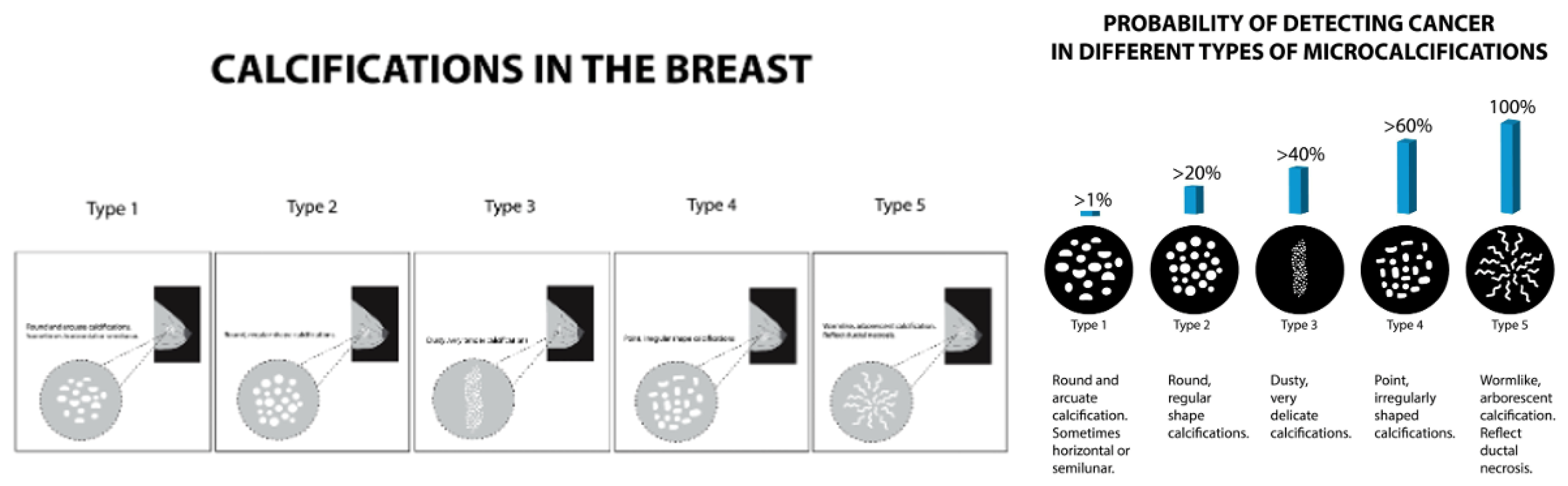
Figure 2.
Breast mammary duct with illustrated benign and malignant calcification patterns as outlined in BI-RADS classifications: I) amorphous II) milk of calcium III) fine linear branching, IV) course heterogeneous.
Figure 2.
Breast mammary duct with illustrated benign and malignant calcification patterns as outlined in BI-RADS classifications: I) amorphous II) milk of calcium III) fine linear branching, IV) course heterogeneous.
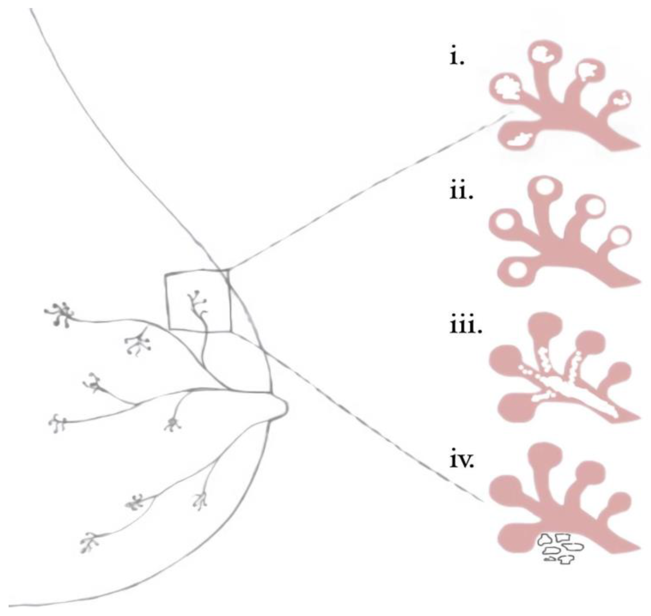
Figure 3.
Sweep Angle in Digital Breast Tomosynthesis. Wider sweep angles can visualize larger areas with lower resolution, while narrower angles provide more resolution over a smaller area, potentially improving the visualization of microcalcifications. This tradeoff and other factors such as filtration, focal spot, detector, and reconstruction methods require thorough phantom tests to determine the most effective DBT system for microcalcification evaluation.
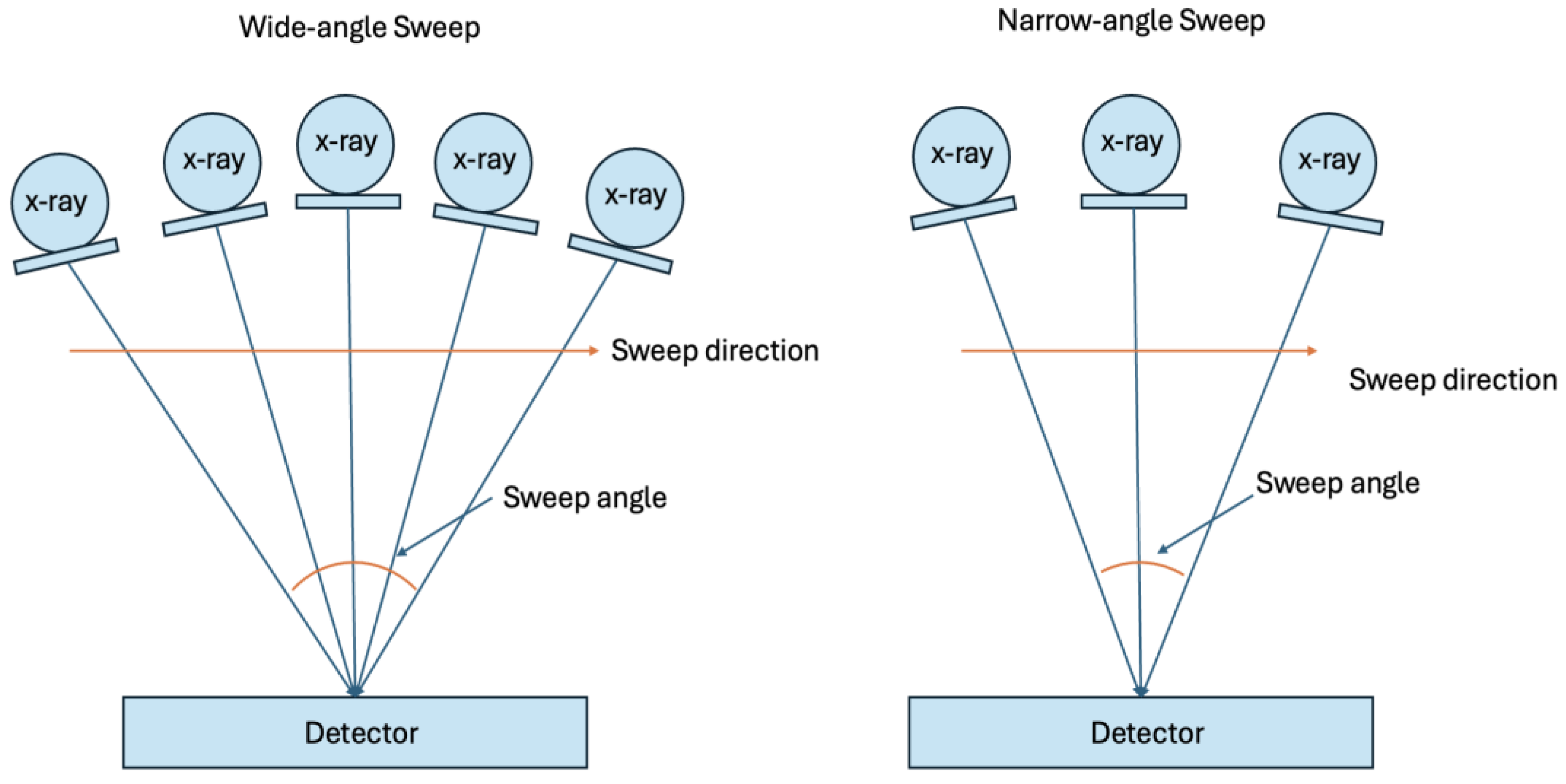
Figure 4.
Magnification and spot compression in DBT. Magnification and spot compression techniques improve the visualization of microcalcifications in DBT. Magnification increases the distance between the breast and the detector. SOD=Subject-to-Object Distance, OID=Object-to-Image Distance.
Figure 4.
Magnification and spot compression in DBT. Magnification and spot compression techniques improve the visualization of microcalcifications in DBT. Magnification increases the distance between the breast and the detector. SOD=Subject-to-Object Distance, OID=Object-to-Image Distance.
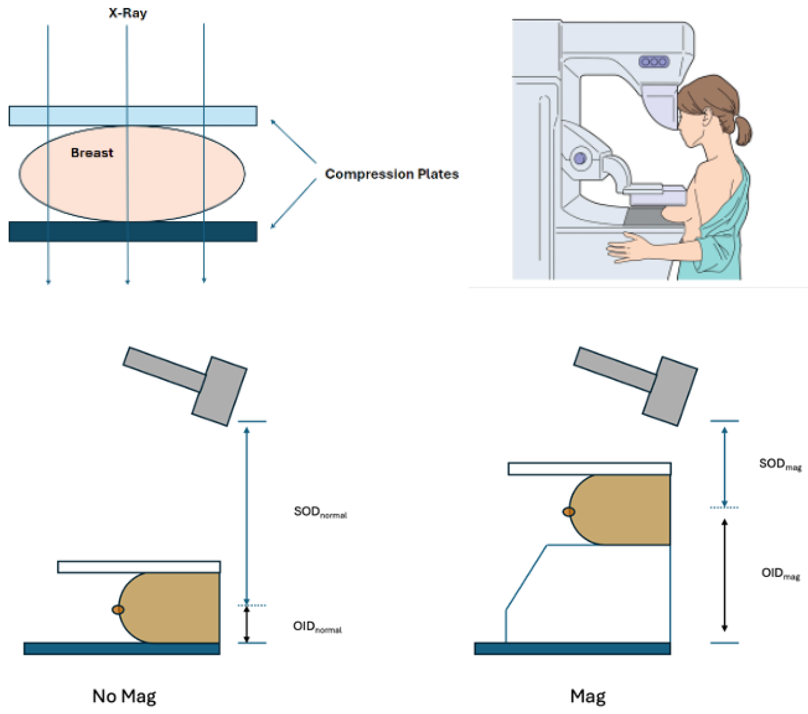
Figure 5.
The American College of Radiology (ACR) phantom is used for quality control in mammography systems, including digital breast tomosynthesis (DBT). The phantom also contains rudimentary elements that mimic breast tissue and abnormalities like microcalcifications and masses. The ACR guidelines ensure consistent and reliable image quality across different mammography systems.
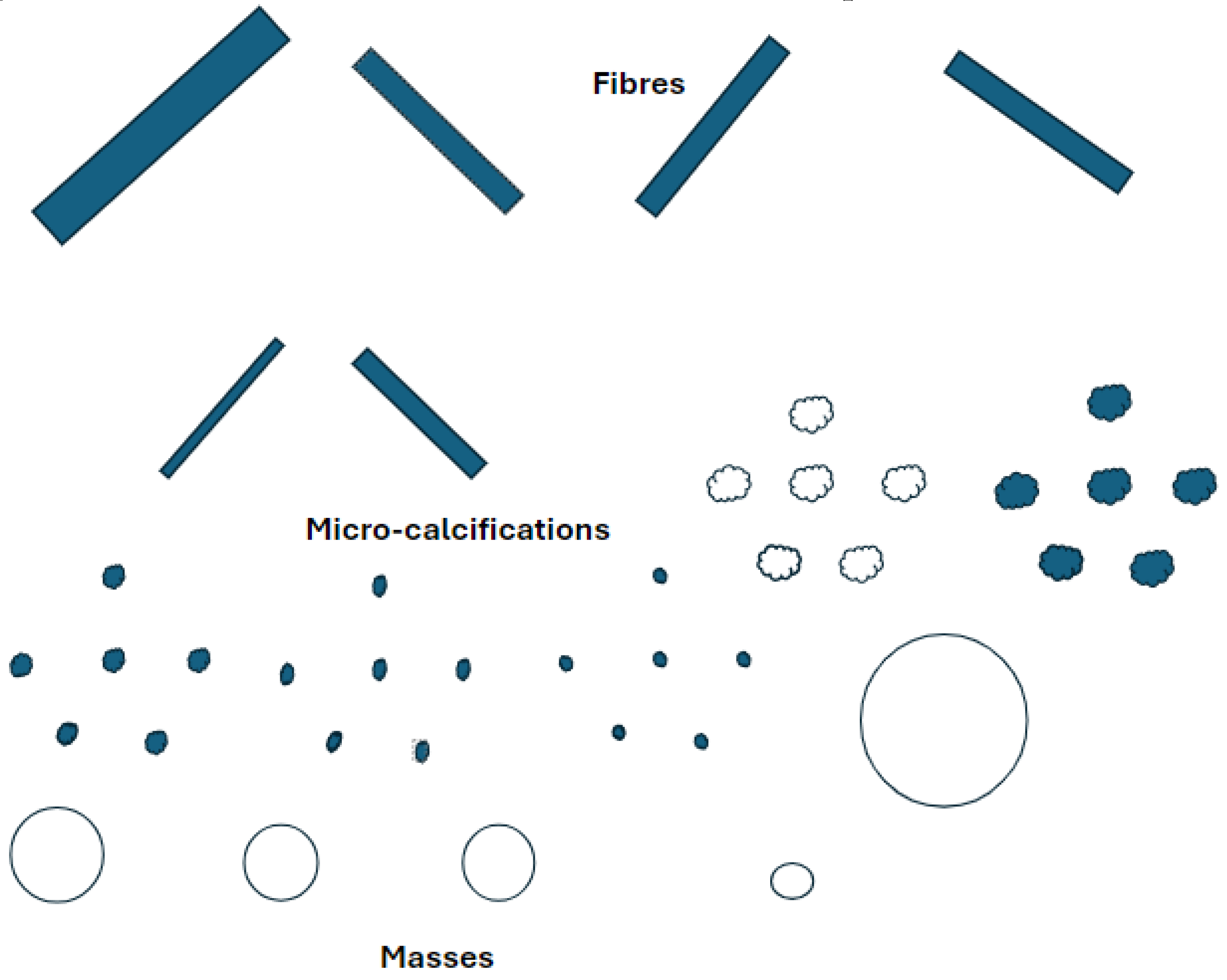
Figure 6.
Crystals with ~0.1 mm resolution were successfully grown using standard dolomite rock and evaporation techniques, with potential for further enhancement through advanced laboratory methods.
Figure 6.
Crystals with ~0.1 mm resolution were successfully grown using standard dolomite rock and evaporation techniques, with potential for further enhancement through advanced laboratory methods.
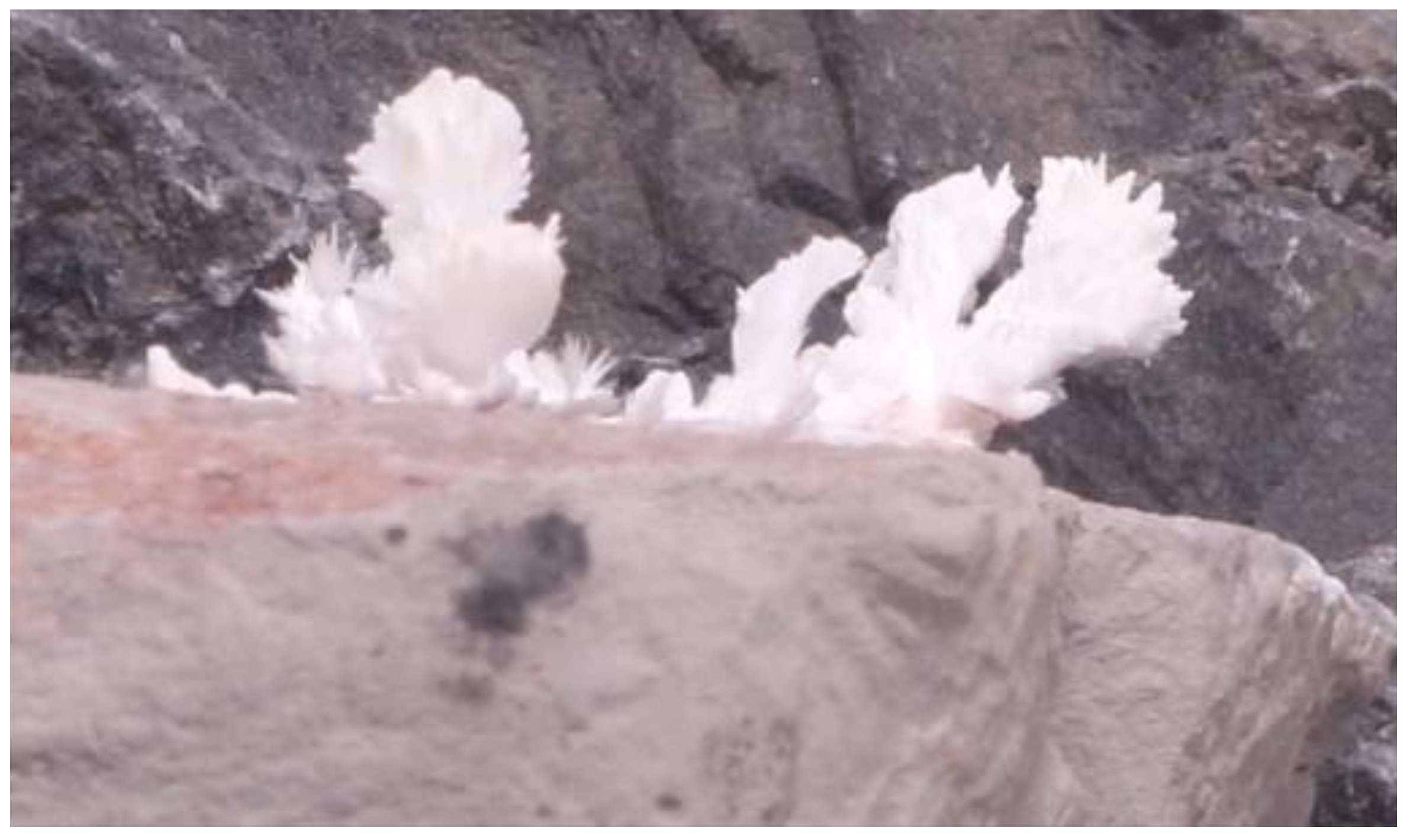
Figure 7.
The flow diagram illustrates the steps for each of the three methods: evaporation, transplantation, and injection.
Figure 7.
The flow diagram illustrates the steps for each of the three methods: evaporation, transplantation, and injection.
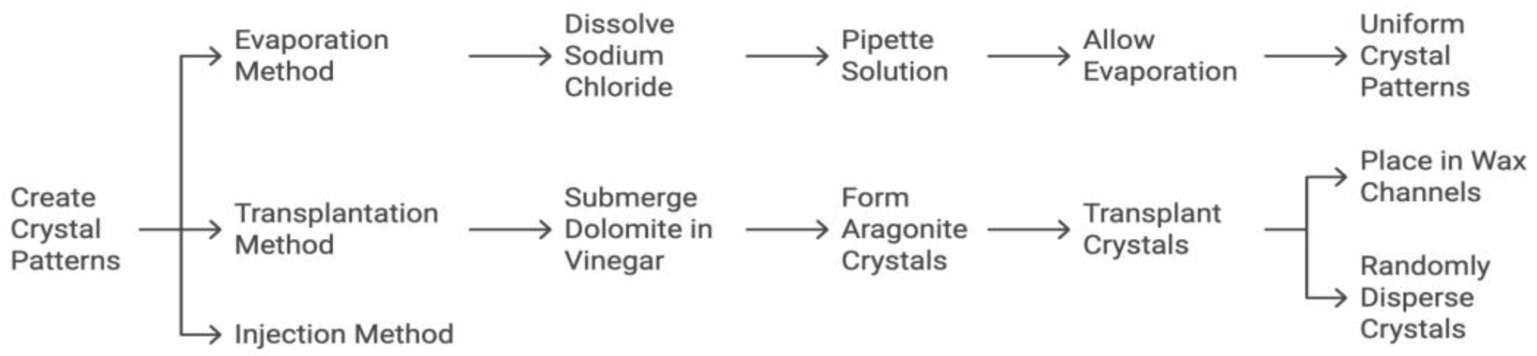
Figure 8.
The flow diagram details the steps of modeling the phantom. The third image depicts stacked calcification patterns between three layers of wax. This creates more dimension within the phantom and can more accurately model widely dispersed calcifications as opposed to isolated calcifications.

Figure 9.
(A) Models of wax phantoms designed to simulate microcalcification detection in DBT imaging. Each phantom features variations in density, pattern, size, and composition of calcifications. By providing a standardized model compatible across various mammography systems, these phantoms support consistent, accurate assessments of calcifications, especially in cases involving subtle or complex calcification shapes; (B) Tomosynthesis image of sodium chloride crystals arranged in various patterns such as heterogeneous clusters and fine linear branches; (C) Radiographic image of a control calcium carbonate crystal grown on dolomite rock and measured to determine if it appropriately models the size and shape of a malignant calcification modeled in BI-RADS. (A) Models of wax phantoms designed to simulate microcalcification detection in DBT imaging. Each phantom features variations in density, pattern, size, and composition of calcifications. By providing a standardized model compatible across various mammography systems, these phantoms support consistent, accurate assessments of calcifications, especially in cases involving subtle or complex calcification shapes; (B) Tomosynthesis image of sodium chloride crystals arranged in various patterns such as heterogeneous clusters and fine linear branches; (C) Radiographic image of a control calcium carbonate crystal grown on dolomite rock and measured to determine if it appropriately models the size and shape of a malignant calcification modeled in BI-RADS.
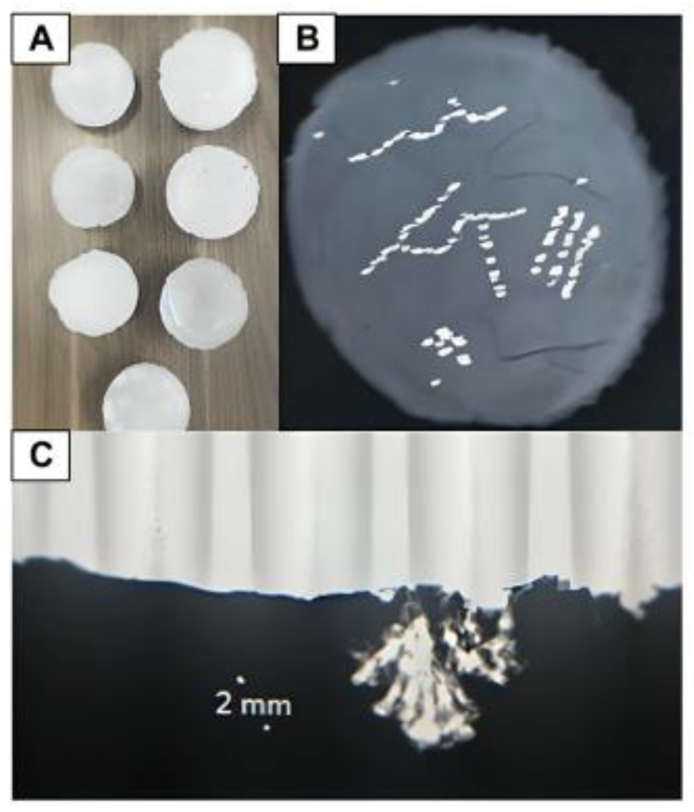
Figure 10.
(A) A phantom being scanned using DBT; (B) Three phantom renditions made with calcium chloride crystals dispersed in differing calcification patterns within microcrystalline wax; (C) A paraffin wax phantom that contains NaCl calcifications in various distributions, including amorphous and fine-branched linear patterns.
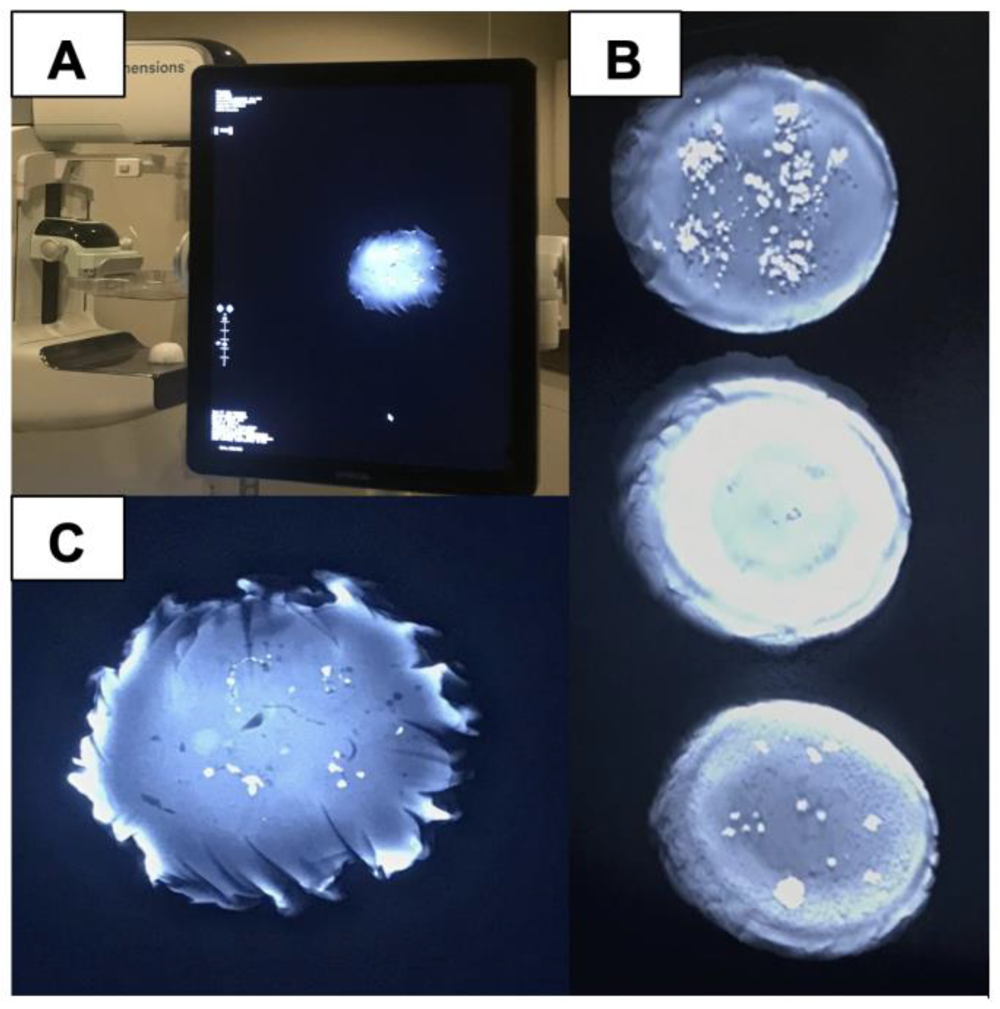
Figure 11.
Comparison of cost and benefits between microcrystalline and paraffin wax when considering large-scale production of wax phantoms for future implications.
Figure 11.
Comparison of cost and benefits between microcrystalline and paraffin wax when considering large-scale production of wax phantoms for future implications.
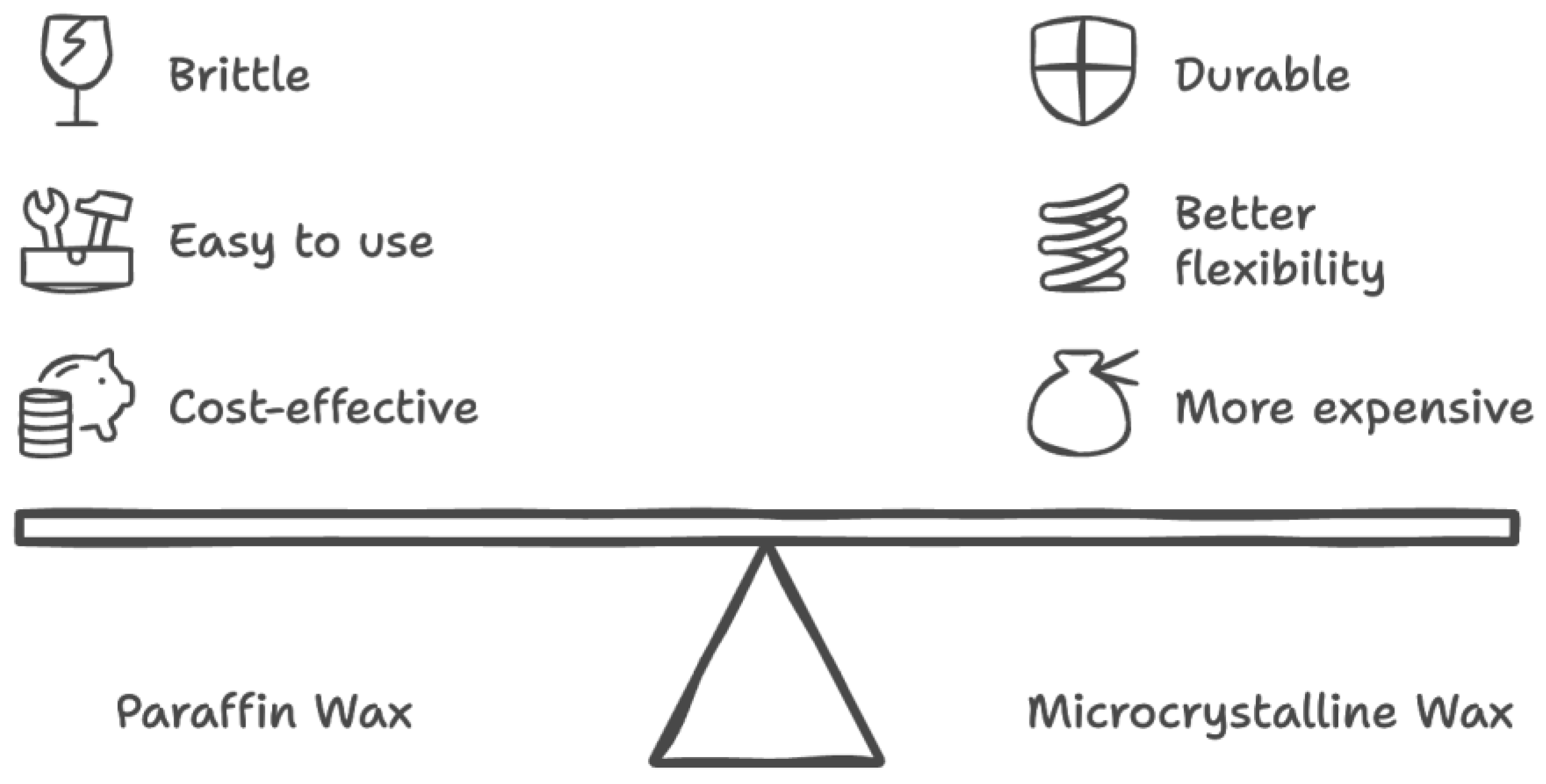
Figure 12.
Magnification Mode of our phantom image is shown on the left. The tomosynthesis image is shown on the right; the tomosynthesis image of calcium carbonate embedded within microcrystalline wax to model calcification in the breast is done in a phantom and can be replicated on different machines during the development and evaluation of systems.
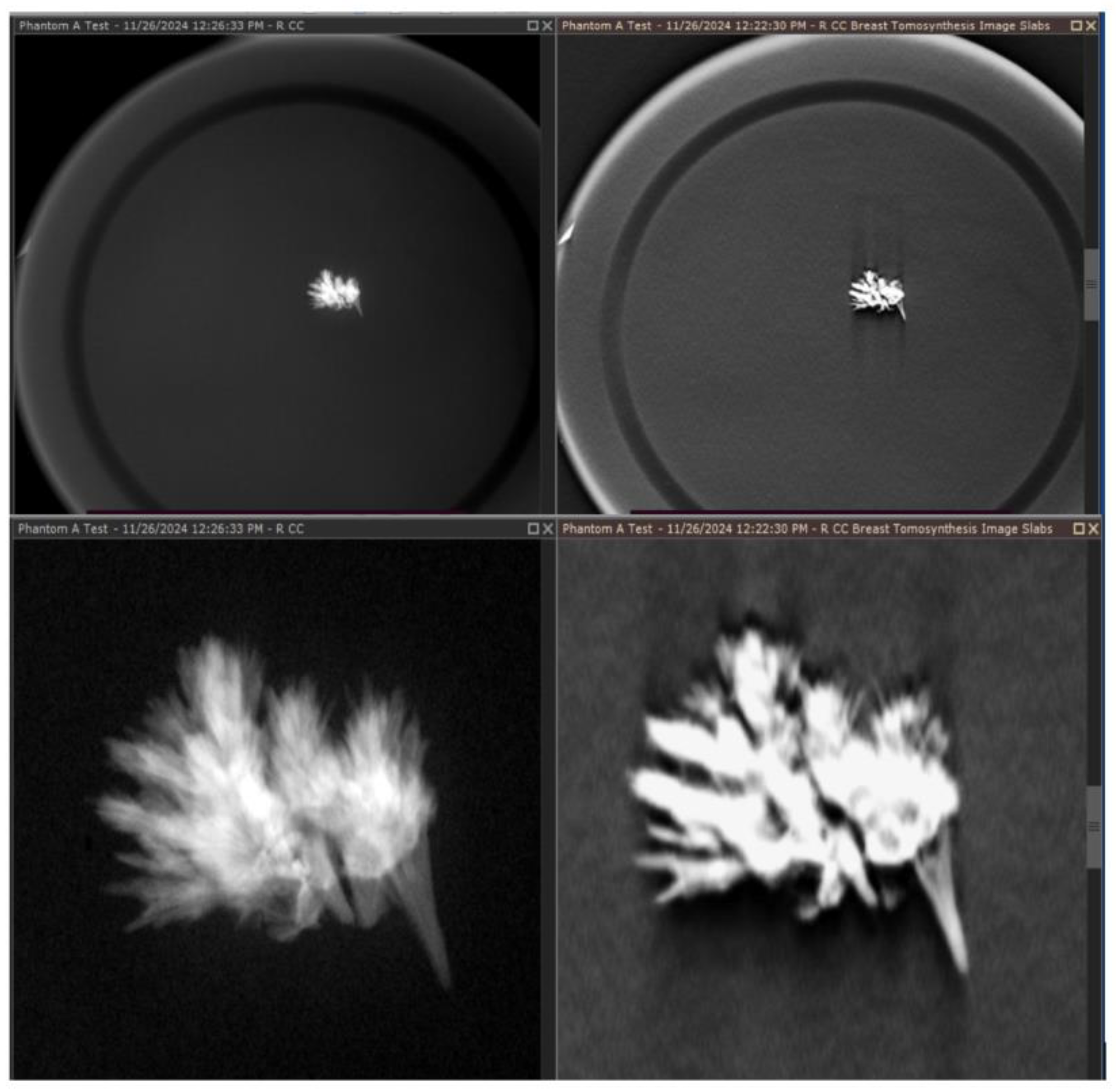

Table 1.
Differences between vendors and various factors used in their mammography scanners.
| Company Name | Fujifilm Medical Systems U.S.A. Inc. | GE Healthcare | Hologic | Siemens Healthineers |
| Scan Angle | 15 degrees | 25-degree sweep angle for DBT | 15 degrees | 50 degrees |
| Matrix, pixels | 24 x 30 cm: 4,728 x 5,928 pixels | 2,850 x 2,394 pixels | 3,328 x 4,096 | 2,816 x 3,584 |
| Reconstruction Style Type (CCD, CsI, aSe) | aSe | CsI scintillator, single-piece construction | aSe | aSe |
| Reconstruction Style | ISR (Iterative Super Resolution) |
Iterative reconstruction algorithm, called ASiRDB | FBP | FBP with iterative optimizations |
| Focal Spot Size, mm | 0.3 mm | 0.3mm with a High ratio grid (11:1) | 0.3 mm | 0.15 / 0.3 mm |
* Differences between imaging quality amongst mammography vendors that arise from various factors, including technologically differing approaches to 3D digital breast tomosynthesis configurations, such as scan or sweep angles. These differences underscore the need for a standardized comparison target that includes advanced phantoms to ensure consistency in image quality.
Disclaimer/Publisher’s Note: The statements, opinions and data contained in all publications are solely those of the individual author(s) and contributor(s) and not of MDPI and/or the editor(s). MDPI and/or the editor(s) disclaim responsibility for any injury to people or property resulting from any ideas, methods, instructions or products referred to in the content. |
© 2024 by the authors. Licensee MDPI, Basel, Switzerland. This article is an open access article distributed under the terms and conditions of the Creative Commons Attribution (CC BY) license (https://creativecommons.org/licenses/by/4.0/).
Copyright: This open access article is published under a Creative Commons CC BY 4.0 license, which permit the free download, distribution, and reuse, provided that the author and preprint are cited in any reuse.


