Submitted:
06 December 2024
Posted:
10 December 2024
You are already at the latest version
Abstract
An asymptotic analytical method is proposed to study the thermal post-buckling behaviors of fiber-reinforced composite (FRC) laminated beams with geometric imperfections employing a modified zig-zag beam model. The beam model satisfies the discontinuity of the shear deformation at the interlayer interfaces and the stress boundary conditions on upper and lower surfaces. The imperfection is assumed to possess the same shape as the buckling mode and the in-plane boundary conditions supposed immovable. A two-step perturbation method is used to solve the nonlinear governing equations and obtain the equilibrium path. Subsequently, the initial defect sensitivity of the post-buckling behaviors is analyzed and the existence of the equilibrium path of bifurcation type of perfect beams is discussed in depth by plotting the load-deflection curves of beams with different boundary conditions and ply modes. Effects of slenderness ratio, elastic modulus ratio, thermal expansion coefficient ratio, ply modes, supported boundaries on the buckling and post-buckling behaviors are also investigated. Numerical results suggest the necessity to consider the zig-zag displacement fields for buckling instability analysis of general asymmetric FRC laminated beams when the thickness of the beams or the ratio of the two in-plane Young’s moduli is large.
Keywords:
Geometric imperfection
; higher-order shear deformation zig-zag model
; thermal post-buckling
; two-step perturbation
1. Introduction
As a kind of light-weight and high-strength material, fiber-reinforced composites (FRC) are increasingly used in military aircrafts where weight and performance requirements are stringent [1,2,3]. However, the extreme service environment of military aircrafts puts forward higher requirements for the structure safety analysis and design techniques, that is, to be able to predict the nonlinear response of structures under given working conditions, analyze the influence of various factors on the response results and make reliable estimates of the accuracy of prediction results [4,5]. For slender composite structures with immovable boundaries serving in aerospace, both the initial geometric imperfections and the axial compressive internal forces caused by the thermal environment will reduce the axial stiffness and cause structural buckling instability,which requires quantitative and precise analysis. Nowadays, researchers not only focus on how to avoid buckling, but also how to make full use of the bearing capacity of structures in post-buckling due to the requirement of lightweight structure design [6,7]. To achieve this, the accurate prediction of buckling and the accurate analysis of stability and defect sensitivity of the post-buckling equilibrium path is the key point.
Researches on post-buckling behaviors of geometrically imperfect beams have received a good amount of attention in the literatures [8,9,10,11,12] that reveal the important influence of geometric imperfections, support conditions and other factors on structural buckling and post-buckling. Based on Reddy's higher order shear deformation beam theory, the post-buckling behaviors were analyzed of simply supported laminated beams with geometric imperfections considering the temperature-dependent material properties and uniform temperature distribution through the thickness [8,13]. Yaghoobi and Torabi conducted the post-buckling and nonlinear free vibration analysis of geometrically imperfect functionally graded beams resting on nonlinear elastic foundation using the Galerkin’s method and variational iteration method [14]. Wu et al. studied the sensitivity of the post-buckling behaviors of functionally graded carbon nanotube-reinforced composite beams to different types of initial generic geometric imperfections by differential quadrature method and an iteration procedure [9]. Numerical results suggested the post-buckling response is highly sensitive to the imperfection amplitude, especially for the L1-mode imperfection. Mohammadi et al. investigated the effects of nonlocal parameter, geometrical imperfection, and elastic foundation on the static instability of the nonlinear nanobeam in post-buckling, snap through and bifurcation instability based on a size-dependent Euler–Bernoulli beam [15]. Fan and Wang studied the effects of initial thermal bending moment, geometric imperfections and matrix cracking on thermal post-buckling behaviors of beam with carbon nanotube reinforced composite layers and piezoelectric fiber reinforced composite layers based on a higher-order beam theory [16].
Because the accuracy of the results depends largely on the precision of the theory, many scholars have been devoting themselves to the development of the non-linear theories of beams, plates and shells [17,18,19,20]. For decades, the beam models like Euler-Bernoulli beam, Timoshenko beam and higher-order shear deformation beam have been well developed and successfully used for the researches on the static and dynamic characteristics of single-layer homogeneous isotropic beams. However, there will exist some limitations in accuracy if applying these theories to the analysis of laminated structures because these theories do not accurately describe the true displacement distribution of laminated structures that should be continuous in its thickness direction due to the difference of stiffness of the adjacent laminates. In the current terminology, the slope change at the interlayer interface is termed as the zig-zag effect. Researches suggested for laminated structures with large thickness or transverse shear deformation, the free vibration frequencies of structures obtained by the equivalent single-layer theory neglecting the zig-zag effects are quite different from those obtained by the three-dimensional elastic theory [21]. To account for such continuous through-thickness displacement field, a series of layer-wise theories have been proposed which separately assumes displacement variables for each layer and may trace the local variations in each layer more accurately [22]. However, the improvement of accuracy is at the expense of the large number of unknowns proportional to the number of layers. For composite laminated structures with more layers, too many displacement variables make the form of solutions too complex, and the corresponding finite element model is also lack of practical value because of the large number of the nodal DOF. To be refined without increasing calculation costs, the equivalent single-layer zig-zag models have been developed to achieve the accuracy of layer-wise models with a lower number of variables. By adding a zig-zag function to the displacement field of the equivalent single-layer models, Murakami pioneered the development of zig-zag theories in which the continuity condition of displacement could be satisfied and the number of displacement variables could be independent of the number of layers [23]. Carrera modified the zig-zag function to meet the condition that the shear stress component on the upper and lower surfaces of the laminated beam is zero [24]. Numerical results revealed that the multilayered plate and shell theories can be greatly improved by use of this modified zig-zag function. Based on this work, Xie et al. developed a general higher-order shear deformation zig-zag theory for analyzing the aero thermoelastic characteristics of composite laminated panels under supersonic airflows [25]. Inspired by Qu and Carrera E’s work, this study applies the modified higher-order shear deformation zig-zag beam model to the post-buckling analysis of geometrically imperfect FRC laminated beams for the first time, and analyze the accuracy and applicability of the theory considering the zig-zag effect and not considering the zig-zag effect.
A number of analytical and numerical methods have been developed to study the static and dynamic responses of laminated beams. They include, but are not limited to, the variational method [26], Navier type method [27], Galerkin method [28], multiple scales methods [29], Green function method [30], harmonic balance method [31], differential quadrature method [9], finite element method [32], meshless method [33], and perturbation method [34]. For structures modeled by such a refined theory considering the zig-zag effects at the interlayer interface, finite element method is the general method to obtain the numerical solutions [35,36]. For the first time, a two-step perturbation method that has better computation efficiency and is more convenient for parameter analysis is used to obtain the asymptotic analytic solution to the post-buckling behaviors of slender structures modeled by a refined zig-zag theory where the displacement field is represented by a piecewise function.
To the best of the author's knowledge, almost all the researches on the post-buckling analyses of slender structures with geometric imperfections are limited to beams with hinged-hinged ends. In this work, the buckling and post-buckling behaviors of perfect/imperfect hinged-hinged and clamped-clamped FRC laminated beams are systematically studied for the first time. The solution results based on the zig-zag theory and the equivalent single-layer theories are verified and compared in detail, and the applicability of the two kinds of theories are analyzed. Through detailed parameter study, various factors affecting the buckling and post-buckling behaviors of the beam are intuitively presented, and the existence of the equilibrium path of bifurcation type is discussed in detail. It is believed that the current zig-zag models and the used solution methods can be extended to the study on the nonlinear static and dynamic characteristics of laminated or sandwich structures with more precise results.
2. Modeling of FRC Laminated Beams
Consider a laminated composite beam with length L, thickness h, and unit width, consisting of N plies of any kind as shown in Figure 1. The two ends are assumed to be hinged-hinged or clamped-clamped and the in-plane boundary conditions supposed immovable. Considering the large transverse shear deformation of beam and the discontinuity of shear strain at interlayer interface, a zig-zag beam model based on Reddy’s higher-order shear deformation theory is adopted, in which the axial and transverse displacement fields are expressed as
According to Marguerre’s nonlinear theory of structures with initial deflection [36], the geometric equations considering the initial imperfection can be derived
The generalized strain components defined in Eq. (4) can be expressed as
Based on the in-plane bending assumption, stresses in the y direction can be ignored and the constitutive model of the kth layer of the beam under thermal environment can be written as [37]
On the basis of Eqs. (8), the axial normal stress and transverse shear stress at any point in the k-layer of the beam can be further written, according to the model in [39]
The virtual work done by the external force is ignored and the Hamilton energy-variational principle for such a beam is
where is the virtual strain energy, is the virtual kinetic energy, and
Through variational operations, the following equations of motion can be obtained
where
3. Approximate Analytical Solutions of Post-Buckling Response
Because the thermal expansion of structure is regarded as a quasi-static process, the equilibrium equations governing the static response of the beam can be obtained from Eqs. (21) by eliminating the time-dependent terms, those are
Substituting Eq. (6), Eq. (7) and Eq. (14) into Eq. (22) leads to the governing equations expressed by generalized displacements
One notes that Eq. (23a) may be solved for the axial displacement u, and hence it can be eliminated from the other three equations. By integrating Eq. (23) with respect to the spatial coordinate x yields, we can obtain
In Eq. (24), is a constant of integration. Integrate Eq. (24) once more, and one has
and
For a FRC beam with immovable ends, the boundary conditions for central axial displacement can be expressed as , and thus Eqs. (25) can be further written
By substituting Eq. (26a) back into Eq. (24), we can obtain
For a FRC beam with immovable fixed–fixed ends, the boundary conditions can be expressed as
and thus Eqs. (26) can be further simplified as
Substitute Eq. (29a) back into Eq. (24), and we can obtain
From the above analysis, it can be seen that the axial force of a beam with two immovable ends can be expressed as
By the way, Eqs. (29) and Eqs. (30) are still true when the laminated beam is symmetrically layered even if the boundary conditions at both ends are not clamped-clamped.
3.1. Clamped-Clamped Supported
By substituting Eqs. (29b) and Eq. (30) into Eqs (23b-d), the simplified governing equations for clamped-clamped ends can be obtained
To facilitate the mathematical treatment of the governing equations, the following dimensionless parameters are defined
in which
Substitute Eqs. (33) into Eqs. (32) and neglect the higher-order small terms, the following dimensionless equations are obtained
The dimensionless boundary conditions can be expressed as
Although the initial defects of the beam are random, studies have shown that the influence of the waveform defect is the most prominent, so it is assumed that the initial defect of the beam has the same form as the classical solution of the small deflection [10], that is
where is the imperfection parameter. It is worth noting that in the post-buckling stage, the defect parameter is a variable rather than a constant.
A two-step perturbation method is employed to solve Eq. (35) and Eq. (36) and determine the thermal post-buckling equilibrium paths [40]. In the present case, thermal load and the generalized displacements are represented in the following series form,
where is a small perturbation parameter with no physical meaning, and k is the number of terms in series.
By substituting Eq. (38) into Eq. (35), a set of the perturbation differential equations are derived. The first-order perturbation equations are expressed as
:
To solve the above partial differential equations, a set of displacement trial functions that satisfy the boundary conditions is introduced [41]
Substitute Eqs. (37) and Eq. (40) into Eqs. (39), and a set of linear equations can be obtained.
By solving Eqs. (41), the zero-order buckling temperature solutions can be obtained
in which
The second order equations can be written as
:
According to the form of equations, a set of trial functions of second-order generalized displacements satisfying boundary conditions is introduced again.
Substitute Eqs. (45) and Eq. (37) into Eqs. (44), and a set of linear second-order equations can be obtained.
It can be proved that the unique solutions of Eqs. (46) are as follows
The third-order equation can be written as
:
According to the form of the equations, a set of trial functions of third-order generalized displacements satisfying boundary conditions is introduced again.
By substituting Eqs. (37) and Eq. (49) into Eqs. (48) and solving the obtained set of linear third-order equations in a similar way, the second order buckling temperature solutions can be obtained
And
Sufficient accuracy can be obtained by solving up to the third-order perturbation equations, according to [41]. The asymptotic solutions of the dimensionless deflection and thermal load can be written as the form of series expansion.
According to Eq. (52a), we can obtain
Thus, the thermal post-buckling load-deflection relationships are obtained
in which the expression of and can be referred to Eqs. (43).
It's remarkable that if there are no geometric defects in FRC laminated beams with clamped-clamped ends, the post-buckling thermal load-deflection curve of bifurcation type can be obtained, that is
Obviously, the equilibrium path of post-buckling is stable, and by letting , the critical buckling bifurcation points can be obtained
Note that in analytical formulas, m represents the order of buckling modes. By letting m=1, the real post-buckling equilibrium path of clamped-clamped FRC laminated beams can be obtained.
3.2. Hinged-Hinged Supported
By substituting Eqs. (26b) and Eq. (27) into Eqs (23b-d), and neglecting the higher-order small terms, the simplified governing equations for FRC laminated beams with hinged-hinged ends can be obtained
On the basis of Eqs (33), the following dimensionless parameters are further introduced.
where the expression of can be referred to Eqs. (34).
Consequently, the dimensionless governing equations can be expressed as follows
According to [39] , there are two factors that lead to the initial deformation for simply supported asymmetric FRC laminated beam, one is the initial deformation caused by stretching-bending coupling effect, the other is still caused by geometric defects. The initial deformation of the beam is still assumed to satisfy the hinged-hinged boundary and possess the same shape as the buckling mode, that is
Define as the imperfection parameter. The subscript T and G respectively denote thermal moments and geometric imperfection. Also, notice that the defect parameter is a variable rather than a constant in the post-buckling stage.
The solutions of Eqs. (59a-c) can also be determined by a two-step perturbation technique. The generalized displacements and thermal load can be assumed the same form as Eqs. (38), those are
Similar to the methods in section 3.1, by substituting Eqs. (61) into Eqs. (59a-c) and collecting the terms of the same order of , a set of perturbation equations are obtained and up to the third order perturbation equations are required to solve for post-buckling problem.
Assuming the displacement trial functions step by step and substituting them with Eq. (60) into the perturbation equations of each order for solution, the following forms of asymptotic solutions can be obtained.
And
In Eq. (63), similar to results of the beams with clamped-clamped ends, m=1 and the real post-buckling equilibrium path of hinged-hinged FRC laminated beams can be obtained. is taken as the perturbation parameter relating to the dimensionless maximum deflection and can be obtained by substituting into Eq. (62a), that is
Substitute Eq. (64) into Eq. (63) and the post-buckling equilibrium path (load-deflection curve) is obtained as follows
where are expressed as
In particular, if the FRC laminated beams are geometrically perfect and symmetrically layered with respect to the geometric mid-plane, there will be no initial deformation caused by initial thermal moments and geometric defects; hence we will obtain
and the post-buckling equilibrium path can be expressed as
It's obvious that the post-buckling thermal load-deflection curve in this case is of bifurcation type, and the post-buckling equilibrium path is stable. By letting , the critical buckling bifurcation points can be obtained
4. Numerical Results and Discussion
In this section, numerical results of buckling and post-buckling responses of perfect/imperfect FRC laminated beams with different material properties, slenderness ratio, laying methods and two different boundaries (H-H, C-C) are presented for validation and parameter analysis respectively. The material characteristics are presented as follows [42]
4.1. Validation and Comparison
To verify the correctness of the model and method used in this paper, this section ignores geometric defect factors, and calculates dimensionless critical buckling temperatures with different slenderness ratios, elastic modulus ratios and thermal expansion coefficient ratios. The dimensionless buckling temperature is defined by
Furthermore, the results obtained in this paper are compared with those obtained by the equivalent single-layer theories and other numerical methods in the literature, and the causes of the results difference are analyzed.
Table 1 and Table 2 calculate the critical buckling loads of laminated beams with different slenderness ratios under two different ply modes (0°/90°) and (0°/90°/0°), respectively. Since there is no buckling value of bifurcation type for simply supported asymmetric (0°/90°) laminated beams, the critical buckling values in this case are not presented in table 1, which will be further explained in section 4.2. It is obvious that the results of this paper and those obtained by using the equivalent single-layer theory in the literature are mutually confirmed. For asymmetric (0°/90°) laminated beams, when the slenderness ratio is large, the error between the results in this paper and those in the literature is less than 0.5%, because the transverse shear deformation of slender beams is small and the results of different beam theories are close. However, when the slenderness ratio is small, the discontinuity of interlaminar shear strain cannot be neglected and the results obtained by using the equivalent single layer theory in the literature are overestimated. For symmetric (0°/90°/0°) laminated beams, the results of this paper are very close to those obtained by using the equivalent single-layer theory in literature. Therefore, the improvement of the accuracy of the zig-zag beam model in this paper is relatively limited for symmetrically laminated beams.
In Table 3 and Table 4, the results of this paper are compared with those modeled by the equivalent single-layer high-order shear deformation theories. For asymmetric (0°/90°) laminated beams, when the ratio of elastic modulus and thermal expansion coefficient is small, the errors between the results obtained in this paper and those obtained by the equivalent single layer theory in literature are very small. Conversely, when and are relatively large, the error of the results is relatively large, approaching 10%. Comparatively speaking, the ratio of elastic modulus has a much greater effect on the accuracy of the results than the ratio of thermal expansion coefficient. When is large, the mechanical properties of materials in two orthogonal directions are quite different and the characteristic of the discontinuity of interlaminar strain cannot be neglected. The results obtained by the equivalent single-layer theory will be relatively high. For symmetric (0°/90°/0°) laminated beams, whether simply or fixedly supported, similar results can be obtained that the results of this paper are very close to those obtained by using the equivalent single-layer theory in literature. Therefore, the improvement of the accuracy of the zig-zag beam model in this paper is relatively limited for symmetrically laminated beams.
4.2. Parameter Analysis
In this section, the material properties of Eqs. (70) are still selected, and numerical examples are given to analyze the various factors affecting the post-buckling characteristics of the FRC laminated beams.
Table 5 reveals that under the assumption of in-plane bending, no matter whether the laminated beams are simply supported at both ends or clamped at both ends, the antisymmetric angle-ply laminated beams have the same bifurcated equilibrium path as the symmetric angle-ply laminated beams. This phenomenon can also be verified by Eqs. (13), that is, the equivalent axial tension-compression stiffness and transverse shear stiffness of the two layers with same absolute values of the ply angle are equal. Therefore, we can draw a conclusion that when the beam is symmetrically or anti-symmetrically laminated, there exists the equilibrium path of bifurcation for simply supported laminated beams, while other ply modes will make the geometric and physical neutral surfaces of the laminated beams do not coincide, resulting in tension-bending coupling effect, so that there is no bifurcated equilibrium path.
Figure 2 reflects the effects of elastic modulus ratio and slenderness ratio on the critical buckling temperature of bifurcation type for perfect FRC laminated beams with immovable clamped-clamped and hinged-hinged ends and different ply-angles. From the above, it is found that for simply supported laminated beams, if the absolute values of the ply angles of the two symmetrical layers in geometry are different, there is no critical buckling value of bifurcation type, so the buckling problem in this case is not considered. As can be seen from the figures, the critical buckling value generally increases first and then decreases with the increase of elastic modulus ratio , and the increase of slenderness ratio L/h will delay the decrease of critical buckling value with the increase of elastic modulus ratio . For the given two boundary conditions, fixed support at both ends has higher buckling strength than simple support at both ends. One can also find that for a given number of common ply modes, when the ratio of elasticity modulus is small, [0°/45°/0°] beams have the best ability to resist instability, otherwise [0°/90°/0°] beams are the best, while [45°/-45°/45°] and [45°/-45°] are the worst ply modes to resist buckling.
Figure 3 shows the effects of slenderness ratio on the critical buckling temperature of bifurcation type for perfect symmetrically layered FRC laminated beams with hinged-hinged and clamped-clamped ends. One can find the boundary conditions have greater influence on the buckling strength than the ply angles in the case of given material parameters and that the critical buckling value of beams may decrease sharply with the increase of slenderness ratio.
Figure 4 and Figure 5 study the effect of thermal expansion coefficient ratio on the critical buckling temperature load and post-buckling behaviors for perfect and imperfect FRC laminated beams under different influencing factors. Numerical results suggest that with the increase of thermal expansion coefficient ratio , the critical buckling temperature decreases and post-buckling load-bearing capacity decreases. Further, it can be found that the smaller the elastic modulus ratio , the faster the buckling value decreases. It can also be found that the influence of elastic modulus ratio on critical buckling load is not only affected by the paving angles and slenderness ratio, but also by thermal expansion coefficient ratio.
Figure 6 compares the post-buckling equilibrium path curves of (45°/-45°/45°) symmetrically laminated beams with different initial imperfection rates. As can be seen from the figure, the laminated beam structures are not sensitive to initial geometric imperfections in general, and the post-buckling equilibrium path is stable. It can be concluded that for perfect symmetrically paved laminated beams, whether simply supported or fixed at both ends, the whole equilibrium path is of bifurcation type. With the increase of defect rate, the bearing capacity of beams decreases at the initial post-buckling stage, but in the deep post-buckling stage, contrary to what one might suppose, the initial defect rate can enhance the bending stiffness of the beam to a certain extent. Note that that equilibrium path of bifurcation type does not exist for laminated beams with initial imperfections.
Figure 7 investigates the influence of elastic modulus ratio on the post-buckling equilibrium paths of symmetrically laminated beams with two different kinds of boundaries conditions and ply angles. It is obvious that laminated beams with fixed ends have better post-buckling bearing capacity than simply supported beams at both ends, which can also be verified by Figure 5 and Figure 6. However, the influence of elastic modulus ratio on the post-buckling equilibrium path of beams is also affected by the ply angles and slenderness ratio implied by Figure 2, and it is difficult to simply explain how the elastic modulus ratio influences the post-buckling equilibrium path. It can be also found that (0°/90°/0°) beams have higher post-buckling strength than (30°/60°/30°) beams.
Figure 8 studies and compares the post-buckling equilibrium paths of hinged-hinged and clamped-clamped laminated beams with different ply modes (symmetrically layered and asymmetrically layered). It can be obtained from Figure 8(a) that for perfect antisymmetric laminated beams, whether simply supported or clamped at both ends, the post-buckling equilibrium paths of bifurcation type always exists because there is no tension-bending coupling effect in this case. However, for other asymmetric laminated beams, if the both ends are simply supported, post-buckling equilibrium path of bifurcation type does not exist due to the existence of the thermal bending moment caused by the eccentricity of neutral surface. From the two figures, it can be seen that (45°/-45°/45°) and (45°/-45°) beams always have the worst post-buckling bearing capacity among the given ply angles.
5. Conclusions
In this paper, a modified zig-zag beam model is used to refine the modeling of laminated beams. The thermal buckling and post-buckling behaviors of both clamped-clamped and hinged-hinged FRC laminated beams with geometric imperfections are systematically studied by using a two-step perturbation technique. Through detailed verification and parameter analysis, the main conclusions can be obtained as follows:
1. For symmetrical or anti-symmetrical laminated beams, the results of the zig-zag beam model and the equivalent single-layer theory in this paper are similar. For general asymmetrical laminated beams, when the slenderness ratio is small or the elastic modulus is large, the results obtained by using the equivalent single-layer theory will be higher.
2. There exists the equilibrium path of bifurcation type for perfect fixed supported laminated beams with arbitrary ply modes and ply angles and for perfect simply supported laminated beams when the beam is symmetrically or anti-symmetrically laminated.
3. The post-buckling of FRC laminated beams is insensitive to initial imperfections and the equilibrium path is stable. Also, initial geometric imperfections will reduce the load-carrying capacity of beams in the initial post-buckling stage, but in the deep post-buckling stage, the initial defect can enhance the bending stiffness of the beam to a certain extent.
4. The influence of elastic modulus ratio on the buckling and post-buckling of beam structures is also affected by slenderness ratio, thermal expansion coefficient ratio and pavement angle, but in general, the critical buckling value increases first and then decreases with the increase of elastic modulus ratio .
5. The two-step perturbation technique is also applicable to the higher-order deformation zig-zag beam models where the displacement field is described by piecewise continuous functions.
Author Contributions
Conceptualization, Zhoumi Wang and Qingchun Meng; methodology, Zhoumi Wang; software, Zhoumi Wang; validation, Zhoumi Wang; formal analysis, Zhoumi Wang.; investigation, Zhoumi Wang; resources, Zhoumi Wang; data curation, Zhoumi Wang; writing—original draft preparation, Zhoumi Wang; writing—review and editing, Zhoumi Wang; visualization, Zhoumi Wang; supervision, Qingchun Meng; project administration, Qingchun Meng.; funding acquisition, Qingchun Meng. All authors have read and agreed to the published version of the manuscript.
Funding
This research received no external funding.
Data Availability Statement
This manuscript has no associated data or the data will not be deposited. [Authors’ comment: All data analyzed during this study are presented in this article.].
Conflicts of Interest
The authors declare no conflicts of interest.
References
- Hudson, T,B., Auwaijan, N., Yuan, F.G., 2019. Guided wave-based system for real-time cure monitoring of composites using piezoelectric discs and phase-shifted fiber Bragg gratings. Journal of Composite Materials. 53(7): 969-979.
- Barile, C., Casavola, C., Cililis, F.D., 2019. Mechanical comparison of new composite materials for aerospace applications. Compos. Part B. 162: 122–128.
- Liu, X., Sun, W., Yan, X., Du, D., Liu, H., Li, H., 2023. Nonlinear vibration analysis of carbon fiber-reinforced composites with frequency-dependence and strain-dependence: experimental and theoretical studies. Thin-Walled structures. 183: 110369.
- Christian, W.J.R., DiazDelaO, F.A., Patterson, E.A., 2018. Strain-based damage assessment for accurate residual strength prediction of impacted composite laminates. Composite Structures. 184: 1215-1223.
- Jiang, H., Ren, Y., Zhang, S., Liu, Z., Yu, G., & Xiang, J., 2019. Damage and perforation resistance behaviors induced by projectile impact load on bonding-patch repaired and scarf-patch repaired composite laminates. International Journal of Damage Mechanics, 28(4), 502-537.
- Eltaher, M.A., Mohamed, N., Mohamed, S.A., et al., 2019. Periodic and nonperiodic modes of postbuckling and nonlinear vibration of beams attached to nonlinear foundations. Applied Mathematical Modelling. 75: 414-445.
- Yu, Y., Shen, H.S., Wang, H., et al., 2018. Postbuckling of sandwich plates with graphene-reinforced composite face sheets in thermal environments. Composites Part B: Engineering. 135: 72-83.
- Li, Z.M., Qiao, P., 2015. Thermal postbuckling analysis of anisotropic laminated beams with different boundary conditions resting on two-parameter elastic foundations. European Journal of Mechanics - A/Solids. 54:30-43.
- Wu, H.L., Yang, J., Kitipornchai, S., 2016. Imperfection sensitivity of postbuckling behaviour of functionally graded carbon nanotube-reinforced composite beams. Thin-Walled Structures. 108:225-233.
- Shen, H.S., Reddy, J.N, Yu, Y., 2021. Postbuckling of doubly curved FG-GRC laminated panels subjected to lateral pressure in thermal environments. Mechanics of Advanced Materials and Structures. 28(3):260-270.
- Wu, H.L., Zheng, Z.Q., Guo, J., et al., 2023. Axisymmetric thermal postbuckling of functionally graded graphene nanocomposite annular plates with various geometric imperfections. Thin-Walled Structures 185: 110594.
- Nam, V.H., Doan, C.V., M., Phuong, N.T., 2023. A new analytical approach to the nonlinear buckling and postbuckling behavior of functionally graded graphene reinforced composite laminated cylindrical, parabolic, and half-sinusoid shallow imperfect panels. Polymer Composites. 44(12): 8928-8945.
- Li, Z.M., Yang, D.Q., 2016. Thermal postbuckling analysis of anisotropic laminated beams with tubular cross-section based on higher-order theory. Ocean Engineering. 115:93-106.
- Yaghoobi, H., Torabi, M., 2013. Post-buckling and nonlinear free vibration analysis of geometrically imperfect functionally graded beams resting on nonlinear elastic foundation. Applied Mathematical Modelling. 37(18-19):8324-8340.
- Mohammadi, H., Mahzoon, M., Mohammadi, M., et al., 2014. Postbuckling instability of nonlinear nanobeam with geometric imperfection embedded in elastic foundation. Nonlinear Dynamics. 76(4):2005-2016.
- Fan, Y., Wang, H., 2016. Nonlinear bending and postbuckling analysis of matrix cracked hybrid laminated plates containing carbon nanotube reinforced composite layers in thermal environments. Composites Part B Engineering. 86:1-16.
- Reddy, J.N., 1984. A simple higher-order theory for laminated composite plates. Asme J.appl.mech. 51(4):745-752.
- Thai, C.H, Ferreira, A.J.M, Nguyen-Xuan, H., 2018. Isogeometric analysis of size-dependent isotropic and sandwich functionally graded microplates based on modified strain gradient elasticity theory. Composite Structures. 192: 274-288.
- Amabili, M., Breslavsky, I.D., Reddy, J.N., 2019. Nonlinear higher-order shell theory for incompressible biological hyperelastic materials. Computer Methods in Applied Mechanics and Engineering. 346: 841-861.
- Kefal, A., Hasim, K.A., Yildiz, M., 2019. A novel isogeometric beam element based on mixed form of refined zigzag theory for thick sandwich and multilayered composite beams. Composites Part B: Engineering. 167: 100-121.
- Carrera, E., Boscolo, M., 2010. Classical and mixed finite elements for static and dynamic analysis of piezoelectric plates. International Journal for Numerical Methods in Engineering. 70(10):1135-1181.
- Panteghini, A., Bardella, L., 2017. Structural theory and finite element modelling of linear elastic sandwich beams subject to severe boundary conditions. European Journal of Mechanics - A/Solids. 61:393-407.
- Murakami, H., 1986. Laminated Composite Plate Theory with Improved In-Plane Responses. Journal of Applied Mechanics. 53(3):661.
- Carrera, E., 2004. On the use of the Murakami's zig-zag function in the modeling of layered plates and shells. Computers & Structures. 82(7-8): 541-554.
- Xie, F., Qu, Y., Zhang, W., et al., 2019. Nonlinear aerothermoelastic analysis of composite laminated panels using a general higher-order shear deformation zig-zag theory. International Journal of Mechanical Sciences. 150: 226-237.
- Su, J., Kai, Z., Qu, Y., et al., 2018. A variational formulation for vibration analysis of curved beams with arbitrary eccentric concentrated elements. Archive of Applied Mechanics. 88(7):1089-1104.
- Chanda, A.G., Kontoni, D.P.N., Sahoo, R., 2023. Development of analytical and FEM solutions for static and dynamic analysis of smart piezoelectric laminated composite plates on elastic foundation. Journal of Engineering Mathematics.138(1): 12.
- Yang, S.W., Hao, Y.X., Zhang, W., et al., 2024. Nonlinear Frequency and Bifurcation of Carbon Fiber-Reinforced Polymer Truncated Laminated Conical Shell. Journal of Vibration Engineering & Technologies. 12(1):457-468.
- Mohammadrezazadeh, S., Jafari, A.A., 2021. Nonlinear vibration suppression of laminated composite conical shells on elastic foundations with magnetostrictive layers. Composite Structures. 258: 113323.
- Li, X., Qin, Y., Zhou, Z.H., 2023. Coupled Vibration Analysis of Rotating Composite Laminated Beams in Hygrothermal Environment Using the Green's Function Method. International Journal of Structural Stability and Dynamics. 23(2): 2350016.
- Yadav, A., Amabili, M., Panda, S.K., et al., 2023. Instability analysis of fluid-filled angle-ply laminated circular cylindrical shells subjected to harmonic axial loading. European Journal of Mechanics - A/Solids. 97: 104810.
- Thai, C.H., Nguyen-Xuan, H., 2019. A moving kriging interpolation meshfree method based on naturally stabilized nodal integration scheme for plate analysis. International Journal of Computational Methods. 16(04): 1850100.
- Yang, S.C., Yao, Y., Li, Y.C., et al., 2022. Geometrically Nonlinear Random Response of Stiffened Laminated Plates by Proper-Orthogonal-Decomposition-Based Reduced-Order Modeling. AIAA Journal. 60(3): 1861-1872.
- Nazemizadeh, M., Bakhtiari-Nejad, F., Assadi, A., 2020. Size-dependent nonlinear dynamic modeling and vibration analysis of piezo-laminated nanomechanical resonators using perturbation method. Archive of Applied Mechanics. 90(8): 1659-1672.
- Carrera, E., Valvano, S., Filippi, M., 2018. Classical, higher-order, zig-zag and variable kinematic shell elements for the analysis of composite multilayered structures. European Journal of Mechanics-A/Solids. 72: 97-110.
- Sahoo, R., Singh, B.N., 2014. A new trigonometric zigzag theory for static analysis of laminated composite and sandwich plates. Aerospace Science and Technology. 35:15-28.
- Marguerre, K., Woemle, H.T., 1969. Elastic plates. Blaisdell Publishing Company.
- Emam, S., Eltaher, M.A., 2016. Buckling and postbuckling of composite beams in hygrothermal environments. Composite Structures 152:665-675.
- Shen, H.S., Lin,F., Xiang,Y., 2017. Nonlinear bending and thermal postbuckling of functionally graded graphene-reinforced composite laminated beams resting on elastic foundations. Engineering Structures. 140:89-97.
- Shen, H.S., 2015. Nonlinear analysis of functionally graded fiber reinforced composite laminated beams in hygrothermal environments, Part I: Theory and solutions. Composite Structures. 125(4):698-705.
- Babaei, H., Kiani, Y., Eslami, M.R., 2019. Thermal buckling and post-buckling analysis of geometrically imperfect FGM clamped tubes on nonlinear elastic foundation. Applied Mathematical Modelling. 71: 12-30.
- She, G.L., Yuan, F.G., Ren, Y.R., et al., 2017. On buckling and postbuckling behavior of nanotubes. International journal of engineering science. 121: 130-142.
- Aydogdu, M., 2005. Vibration analysis of cross-ply laminated beams with general boundary conditions by Ritz method. International Journal of Mechanical Sciences. 47(11):1740-1755.
- Nguyen, N.D, Nguyen, T.K., Nguyen, T.N., et al., 2018. New Ritz-solution shape functions for analysis of thermo-mechanical buckling and vibration of laminated composite beams. Composite Structures. 184: 452-460.
- Aydogdu, M., 2007. Thermal buckling analysis of cross-ply laminated composite beams with general boundary conditions. Composites Science and Technology. 67(6):1096-1104.
Figure 1.
Geometry of the laminated beam consisting of N plies.
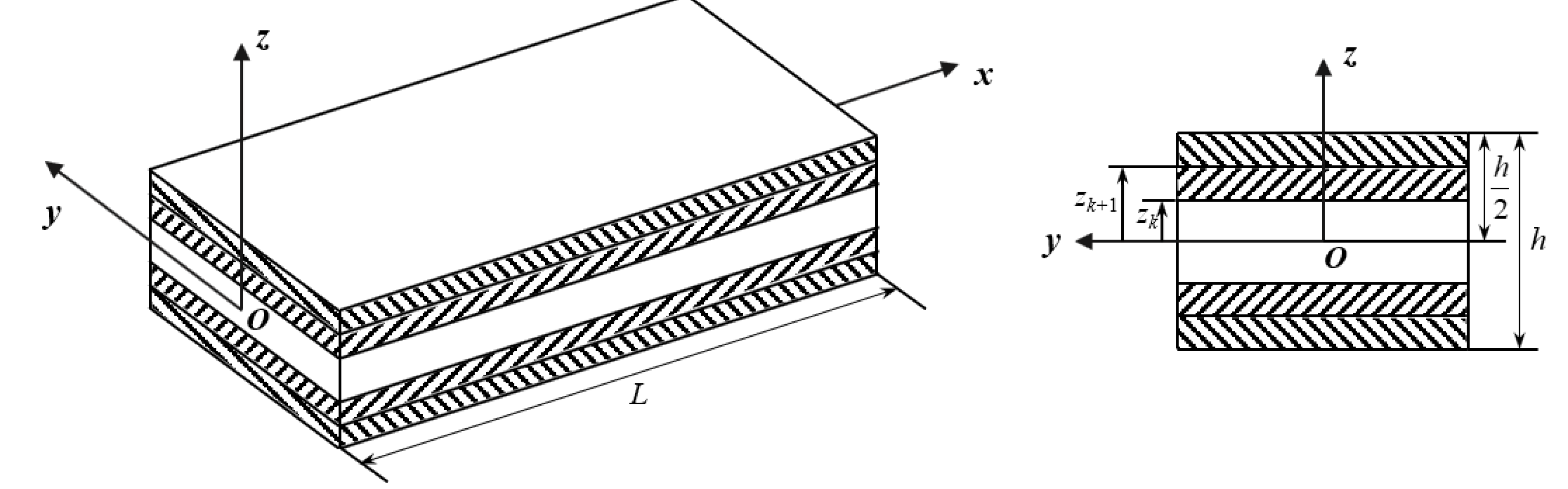
Figure 2.
Effects of elastic modulus ratio and slenderness ratio on the critical buckling temperature of bifurcation type for perfect FRC laminated beams with different ply-angles, (a) asymmetrically layered beam with clamped-clamped ends. (b) symmetrically layered beam with hinged-hinged ends. (c) symmetrically layered beam with clamped-clamped ends.
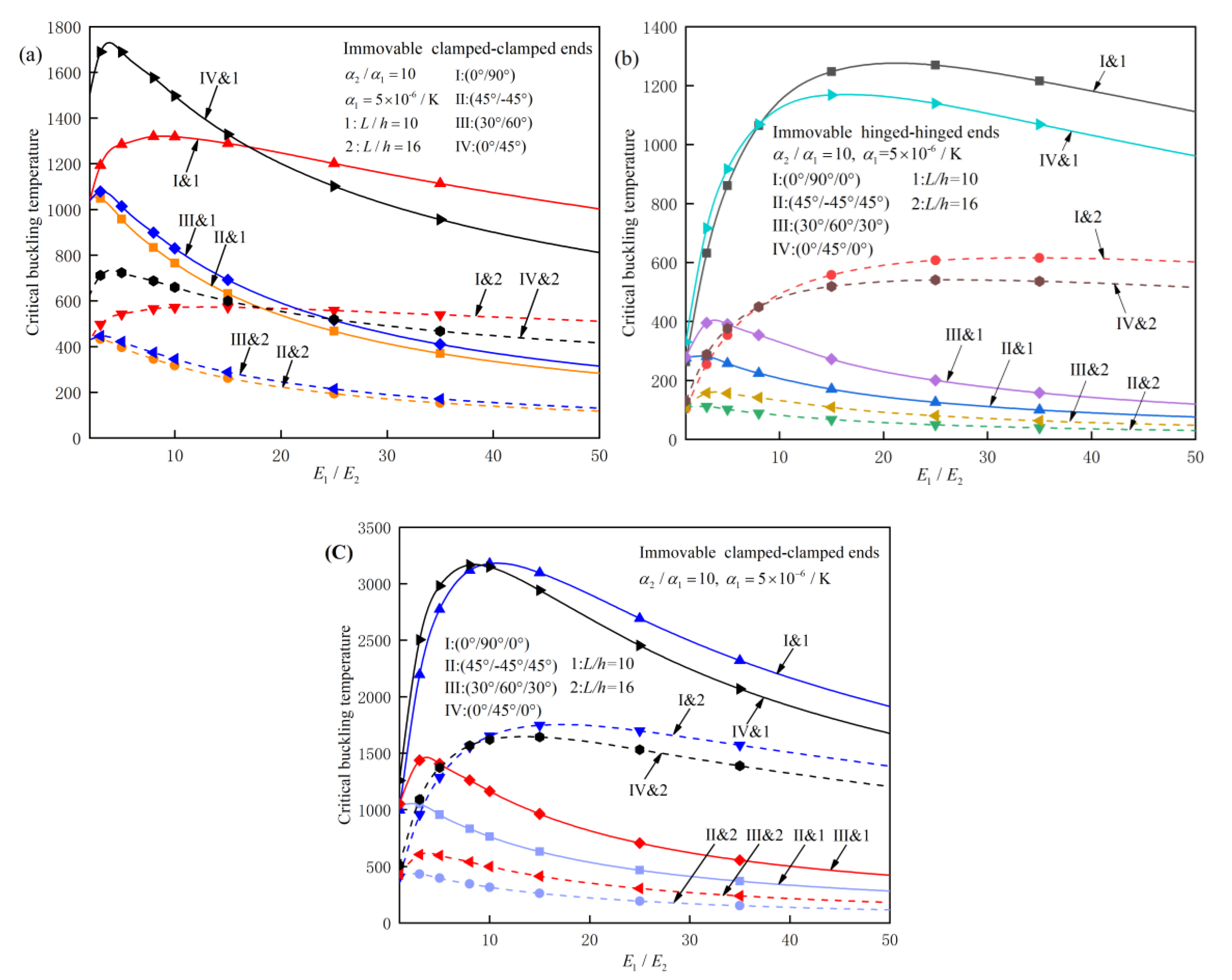
Figure 3.
Effects of slenderness ratio on the critical buckling temperature of bifurcation type for perfect symmetrically layered FRC laminated beams.
Figure 3.
Effects of slenderness ratio on the critical buckling temperature of bifurcation type for perfect symmetrically layered FRC laminated beams.
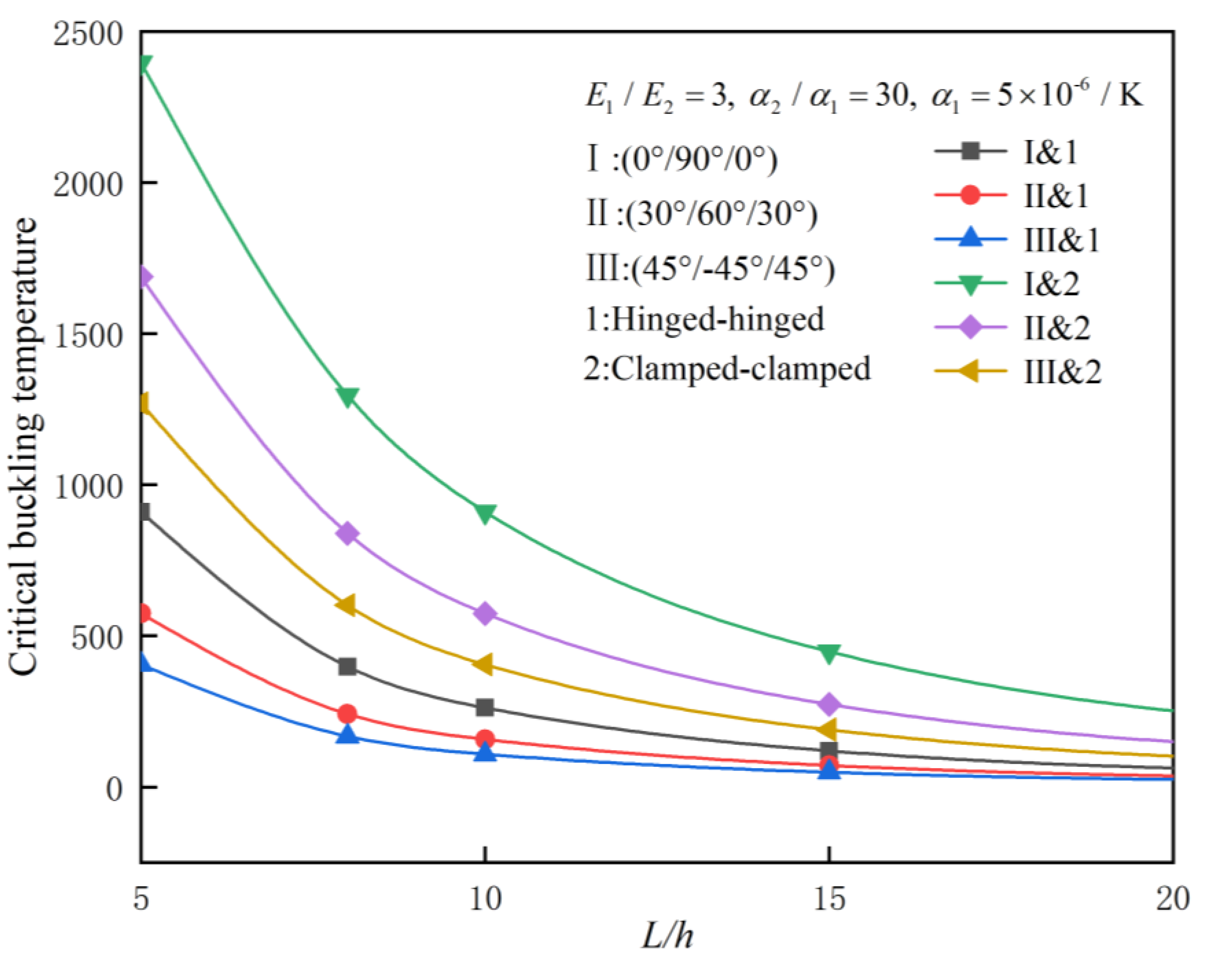
Figure 4.
Effects of thermal expansion coefficient ratio on the critical buckling temperature of bifurcation type for perfect clamped-clamped FRC laminated beams with different ply modes and elastic modulus ratios. (a) asymmetrically layered. (b) symmetrically layered.
Figure 4.
Effects of thermal expansion coefficient ratio on the critical buckling temperature of bifurcation type for perfect clamped-clamped FRC laminated beams with different ply modes and elastic modulus ratios. (a) asymmetrically layered. (b) symmetrically layered.
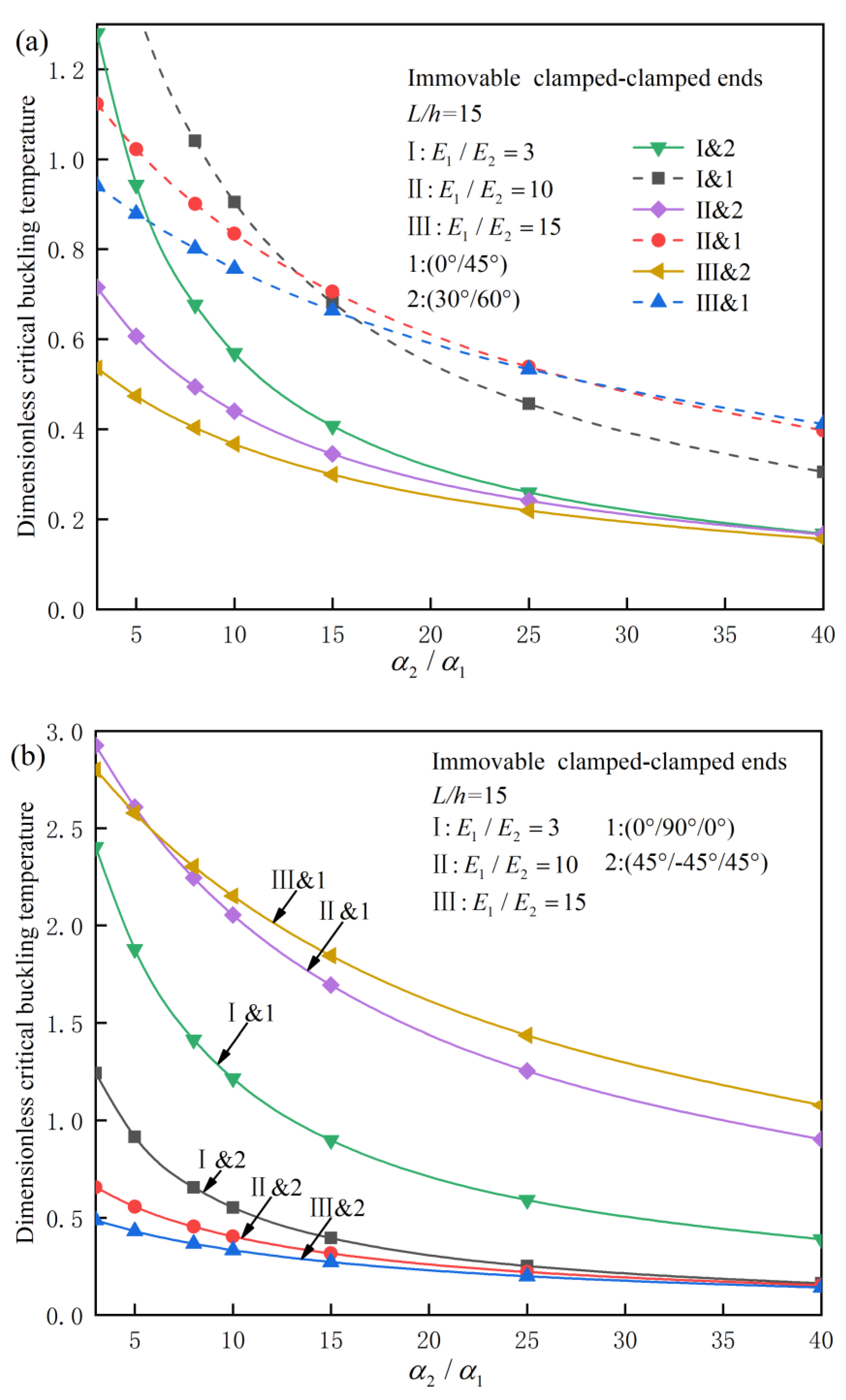
Figure 5.
Effect of different thermal expansion coefficient ratios on the thermal post-buckling behaviors of (45°/0°/45°) symmetrically layered FRC laminated beams under two different boundary conditions.
Figure 5.
Effect of different thermal expansion coefficient ratios on the thermal post-buckling behaviors of (45°/0°/45°) symmetrically layered FRC laminated beams under two different boundary conditions.
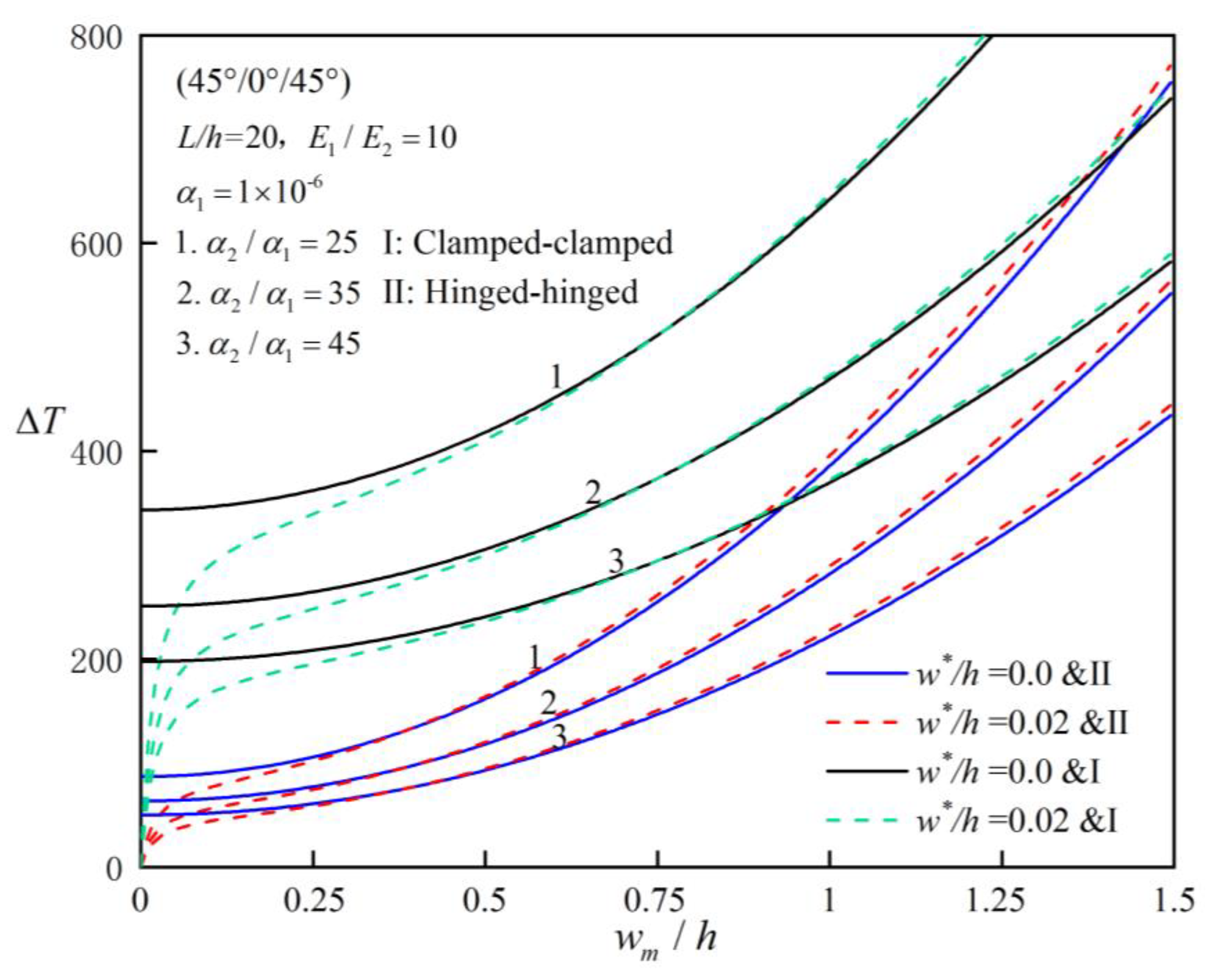
Figure 6.
Effects of different initial imperfection rates on the thermal post-buckling behaviors for (45°/-45°/45°) symmetrically layered FRC laminated beams.
Figure 6.
Effects of different initial imperfection rates on the thermal post-buckling behaviors for (45°/-45°/45°) symmetrically layered FRC laminated beams.
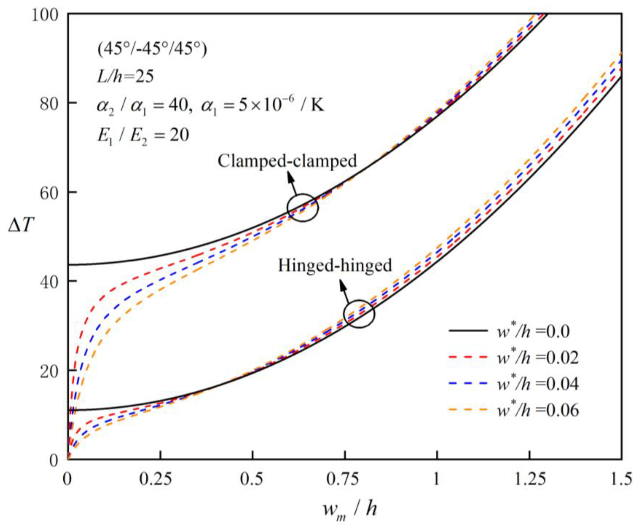
Figure 7.
Effects of different elastic modulus ratios on the thermal post-buckling behaviors for symmetrically layered FRC laminated beams under two different kinds of boundaries conditions and ply angles, (a) (0°/90°/0°). (b) (30°/60°/30°).
Figure 7.
Effects of different elastic modulus ratios on the thermal post-buckling behaviors for symmetrically layered FRC laminated beams under two different kinds of boundaries conditions and ply angles, (a) (0°/90°/0°). (b) (30°/60°/30°).
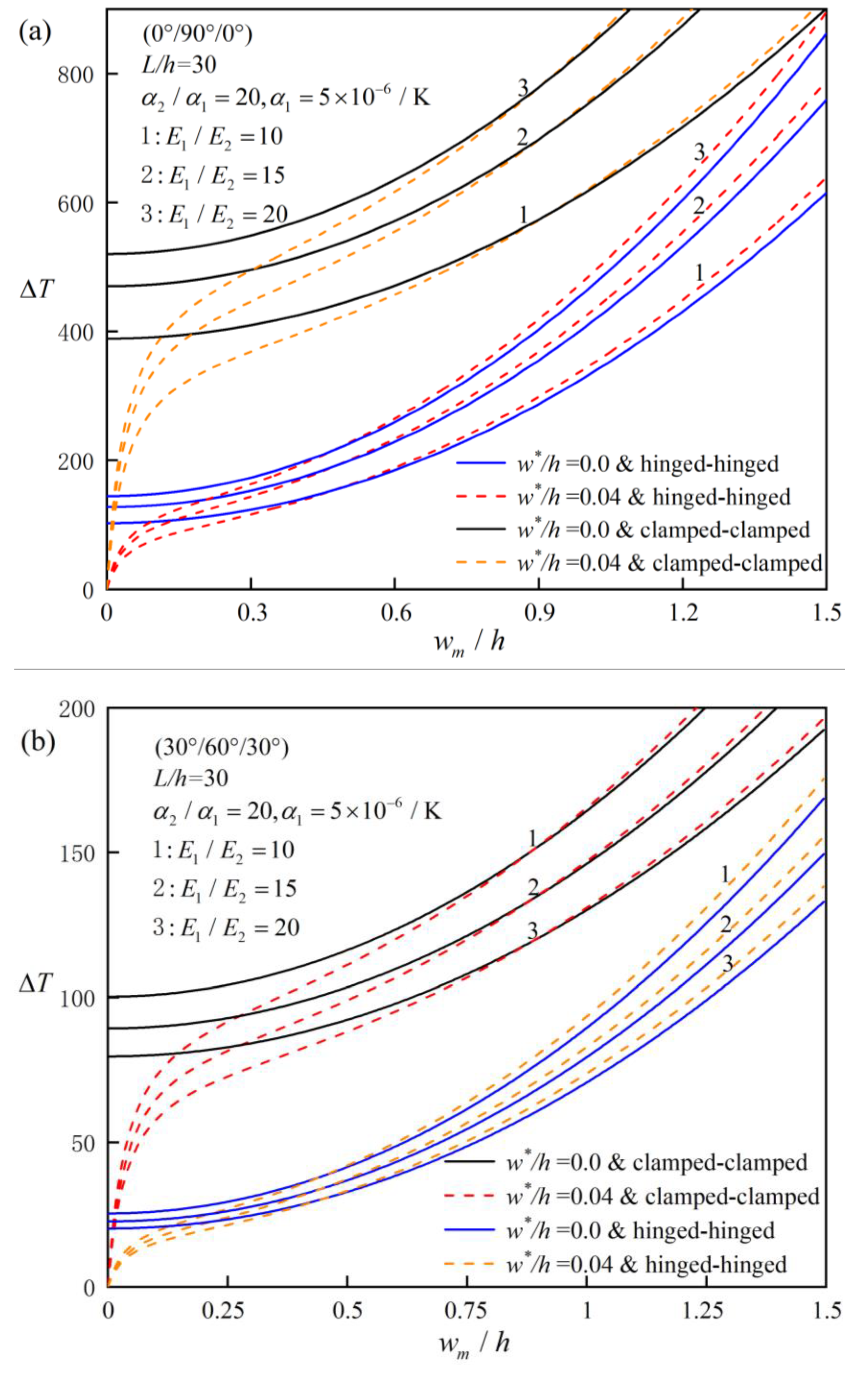
Figure 8.
Effect of different ply modes on the thermal post-buckling behaviors of FRC laminated beams, (a) asymmetrically layered, (b) symmetrically layered.
Figure 8.
Effect of different ply modes on the thermal post-buckling behaviors of FRC laminated beams, (a) asymmetrically layered, (b) symmetrically layered.
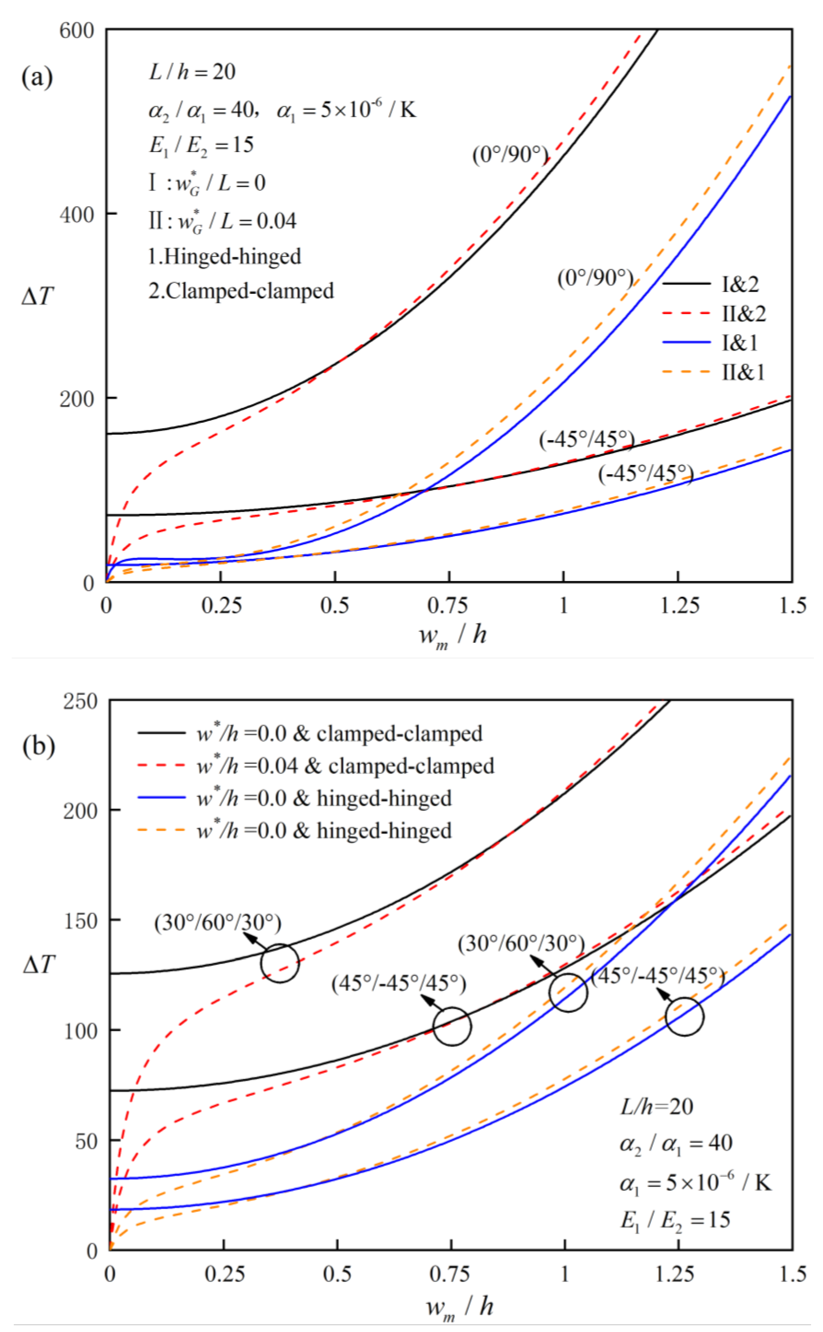

Table 1.
Dimensionless critical buckling temperature of (0°/90°) C-C asymmetric FRC laminated beams () [43,44].
| L/h | Reference | (0°/90°) |
|---|---|---|
| 5 | Present | 0.511 |
| Ngoc-Duong Nguyen | 0.558 | |
| Aydogdu | 0.557 | |
| Khdeir | 0.583 | |
| 10 | Present | 0.850 |
| Ngoc-Duong Nguyen | 0.887 | |
| Khdeir | 0.926 | |
| 20 | Present | 1.029 |
| Ngoc-Duong Nguyen | 1.045 | |
| Aydogdu | 1.092 | |
| Khdeir | 1.090 | |
| 30 | Present | 1.071 |
| Ngoc-Duong Nguyen | 1.081 | |
| 50 | Present | 1.094 |
| Ngoc-Duong Nguyen | 1.100 | |
| Aydogdu | 1.098 | |
| Khdeir | 1.148 |
Table 2.
Dimensionless critical buckling temperature of (0°/90°/0°) symmetric FRC laminated beams () [43,44].
| L/h | Reference | BCs | |
|---|---|---|---|
| H-H | C-C | ||
| 5 | Present | 0.448 | 0.682 |
| Ngoc-Duong Nguyen | 0.450 | 0.682 | |
| Khdeir | 0.468 | 0.710 | |
| 10 | Present | 0.787 | 1.791 |
| Ngoc-Duong Nguyen | 0.791 | 1.798 | |
| Aydogdu | 0.79 | 1.797 | |
| Khdeir | 0.823 | 1.871 | |
| 20 | Present | 0.976 | 3.149 |
| Ngoc-Duong Nguyen | 0.979 | 3.163 | |
| Khdeir | 1.019 | 3.292 | |
| 30 | Present | 1.021 | 3.674 |
| Ngoc-Duong Nguyen | 1.025 | 3.680 | |
| 50 | Present | 1.046 | 4.018 |
| Ngoc-Duong Nguyen | 1.049 | 4.032 | |
| Aydogdu | 1.049 | 4.030 | |
| Khdeir | 1.092 | 4.196 |
Table 3.
Dimensionless critical buckling temperature of (0°/90°) C-C asymmetric FRC laminated beams (L/h=10) [43].
Table 3.
Dimensionless critical buckling temperature of (0°/90°) C-C asymmetric FRC laminated beams (L/h=10) [43].
| BCs | Reference | ||||||
|---|---|---|---|---|---|---|---|
| 3 | 10 | 20 | 50 | 100 | |||
| c-c | 3 | Present | 1.342 | 0.596 | 0.333 | 0.143 | 0.073 |
| Ngoc-Duong Nguyen | 1.368 | 0.608 | 0.339 | 0.146 | 0.075 | ||
| 10 | Present | 1.071 | 0.659 | 0.425 | 0.206 | 0.111 | |
| Ngoc-Duong Nguyen | 1.090 | 0.671 | 0.433 | 0.210 | 0.113 | ||
| 20 | Present | 0.850 | 0.623 | 0.451 | 0.247 | 0.141 | |
| Ngoc-Duong Nguyen | 0.887 | 0.650 | 0.471 | 0.257 | 0.147 | ||
| 40 | Present | 0.643 | 0.537 | 0.434 | 0.276 | 0.171 | |
| Ngoc-Duong Nguyen | 0.709 | 0.592 | 0.478 | 0.304 | 0.189 |
Table 4.
Dimensionless critical buckling temperature of (0°/90°/0°) symmetric FRC laminated beams (L/h=10) [43,44].
| BCs | Reference | ||||||
|---|---|---|---|---|---|---|---|
| 3 | 10 | 20 | 50 | 100 | |||
| H-H | 3 | Present | 0.624 | 0.316 | 0.185 | 0.083 | 0.043 |
| Ngoc-Duong Nguyen | 0.637 | 0.322 | 0.171 | 0.084 | 0.044 | ||
| Aydogudu | 0.637 | 0.323 | 0.189 | 0.293 | 0.153 | ||
| 10 | Present | 0.815 | 0.573 | 0.402 | 0.212 | 0.119 | |
| Ngoc-Duong Nguyen | 0.821 | 0.576 | 0.404 | 0.213 | 0.119 | ||
| 20 | Present | 0.787 | 0.638 | 0.502 | 0.306 | 0.185 | |
| Ngoc-Duong Nguyen | 0.791 | 0.641 | 0.504 | 0.307 | 0.186 | ||
| Khdeir | 0.823 | 0.708 | 0.590 | 0.393 | 0.253 | ||
| 40 | Present | 0.663 | 0.590 | 0.510 | 0.362 | 0.244 | |
| Ngoc-Duong Nguyen | 0.666 | 0.592 | 0.512 | 0.363 | 0.245 | ||
| C-C | 3 | Present | 2.170 | 1.098 | 0.643 | 0.287 | 0.149 |
| Ngoc-Duong Nguyen | 2.212 | 1.119 | 0.656 | 0.293 | 0.137 | ||
| 10 | Present | 2.263 | 1.589 | 1.115 | 0.588 | 0.329 | |
| Ngoc-Duong Nguyen | 2.278 | 1.599 | 1.122 | 0.592 | 0.331 | ||
| 20 | Present | 1.791 | 1.451 | 1.141 | 0.695 | 0.421 | |
| Ngoc-Duong Nguyen | 1.798 | 1.456 | 1.145 | 0.698 | 0.423 | ||
| Aydogudu | 1.804 | 1.462 | 1.148 | 0.699 | 0.423 | ||
| 40 | Present | 1.216 | 1.082 | 0.935 | 0.664 | 0.448 | |
| Ngoc-Duong Nguyen | 1.218 | 1.083 | 0.936 | 0.665 | 0.448 |
Table 5.
Comparison of equilibrium paths of perfect symmetrically and anti-symmetrically layered beams.
Table 5.
Comparison of equilibrium paths of perfect symmetrically and anti-symmetrically layered beams.
| BCs | w/h | Ply-angle | |||
|---|---|---|---|---|---|
| (30°/-30°) | (30°/30°) | (45°/0°/45°) | (45°/0°/-45°) | ||
| H-H | 0 | 233.816 | 233.816 | 177.947 | 177.947 |
| 0.2 | 262.185 | 262.185 | 243.095 | 243.095 | |
| 0.4 | 347.293 | 347.293 | 438.536 | 438.536 | |
| 0.6 | 489.138 | 489.138 | 764.271 | 764.271 | |
| 0.8 | 687.722 | 687.722 | 1220.301 | 1220.301 | |
| 1.0 | 943.044 | 943.044 | 1806.625 | 1806.625 | |
| 1.2 | 1255.104 | 1255.104 | 2523.243 | 2523.243 | |
| 1.4 | 1623.903 | 1623.903 | 3370.155 | 3370.155 | |
| C-C | 0 | 905.482 | 905.482 | 691.368 | 691.368 |
| 0.2 | 933.852 | 933.852 | 756.515 | 756.515 | |
| 0.4 | 1018.959 | 1018.959 | 951.957 | 951.957 | |
| 0.6 | 1160.804 | 1160.804 | 1277.692 | 1277.692 | |
| 0.8 | 1359.388 | 1359.388 | 1733.722 | 1733.722 | |
| 1.0 | 1614.710 | 1614.710 | 2320.046 | 2320.046 | |
| 1.2 | 1926.771 | 1926.771 | 3036.664 | 3036.664 | |
| 1.4 | 2295.569 | 2295.569 | 3883.576 | 3883.576 | |
Disclaimer/Publisher’s Note: The statements, opinions and data contained in all publications are solely those of the individual author(s) and contributor(s) and not of MDPI and/or the editor(s). MDPI and/or the editor(s) disclaim responsibility for any injury to people or property resulting from any ideas, methods, instructions or products referred to in the content. |
© 2024 by the authors. Licensee MDPI, Basel, Switzerland. This article is an open access article distributed under the terms and conditions of the Creative Commons Attribution (CC BY) license (http://creativecommons.org/licenses/by/4.0/).
Copyright: This open access article is published under a Creative Commons CC BY 4.0 license, which permit the free download, distribution, and reuse, provided that the author and preprint are cited in any reuse.


