1. Introduction
This research focuses on the study of a plug flow
tubular reactor because it is very used in the industrial practice for the production of various and important chemicals [1–3]. The functioning of the tubular reactor presents many challenges, such as a strong variation of reactants and products concentrations versus the axial distance of tube constituting the reactor. This variation of concentrations is due mainly to the non-homogeneity caused by the inherent nature of the plug flow of reactants mixture.[4]. There are numerous kinds of tubular reactors such as tubular reactor with recycle exit stream, tubular packed bed reactor, jacketed tubular reactor for exothermic or endothermic reactions and staged feed tubular reactor [5,6]. The staged feed tubular reactor is used in the objective of optimizing a desired concentration product in the case of occurrence a multiple stoechiometric reactions or when it is impossible to premix directly the reactants in the inlet of the reactor due to high
exothermicity of the reaction. These considerations motivate the need for highlighting the effect of the distribution of the staged feed of the co-reactant on the efficiency of the reactor [7,8]. For this purpose, the mathematical model of the staged feed tubular reactor was set and solved using the data related to its nominal operating point [2]. Afterwards, the influence on the outlet conversion rate of the main operative variables and the distribution of the staged feed was assessed.
2. The staged Feed Tubular Reactor
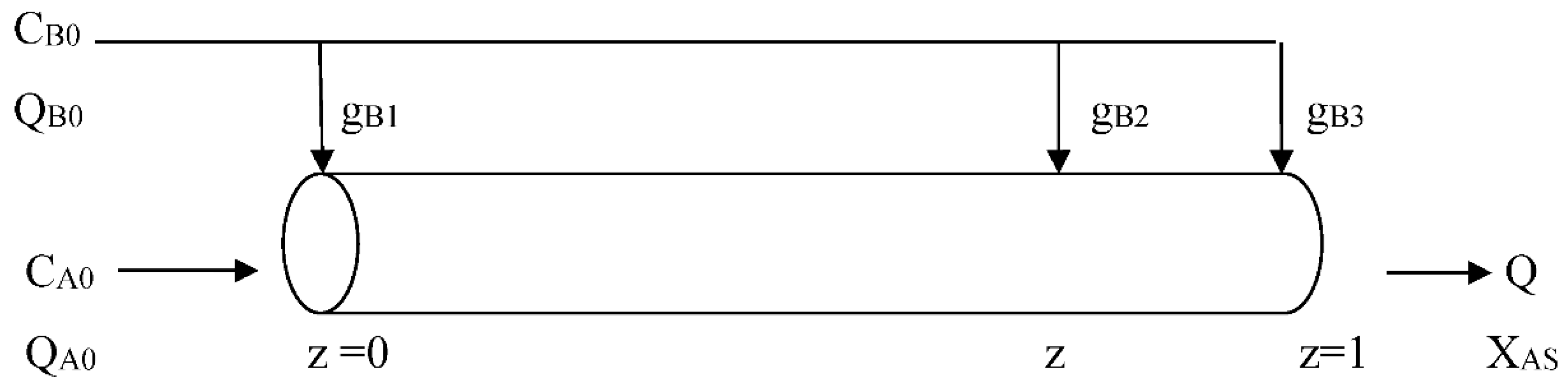
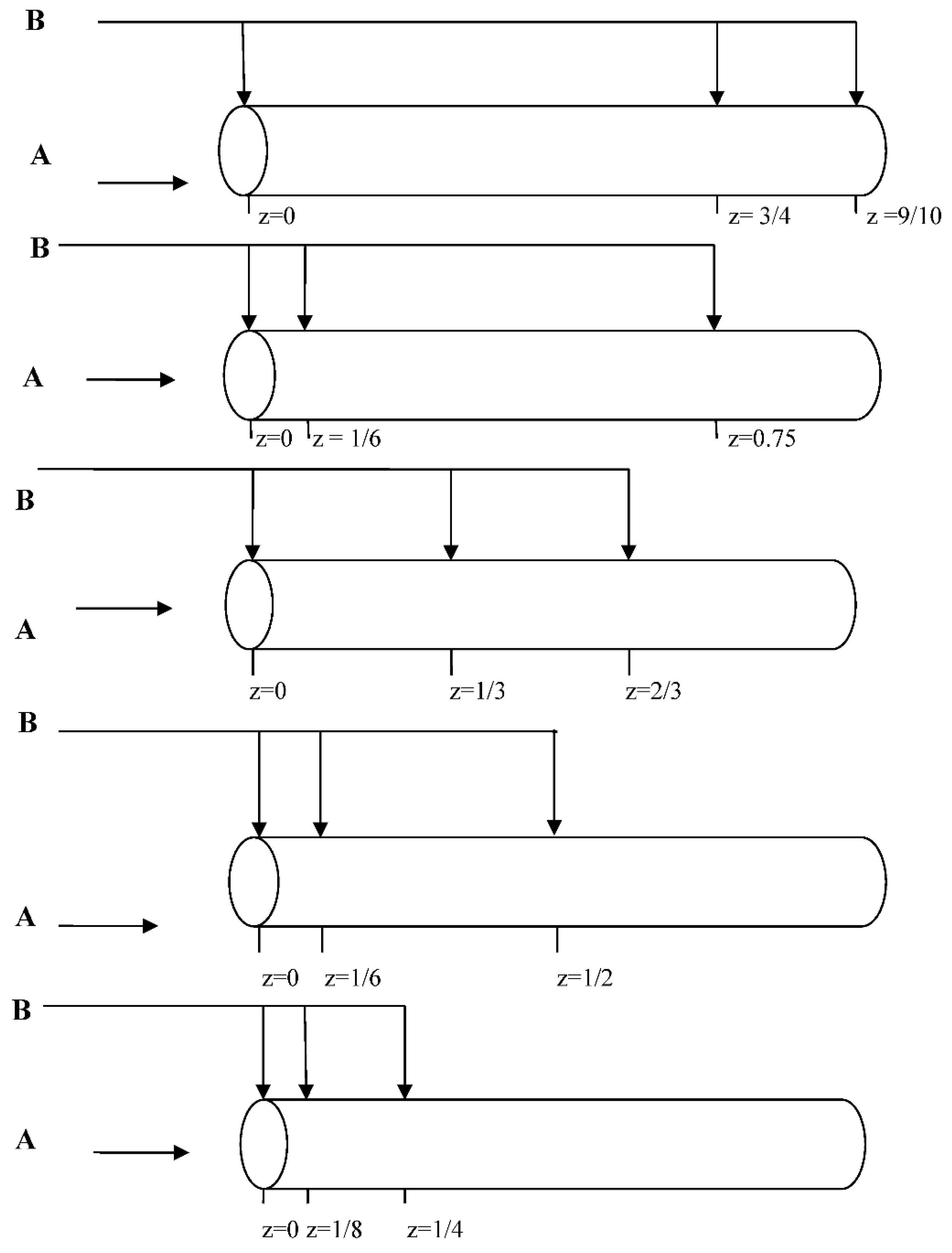
A flowsheet of staged feed tubular reactor is presented in
Figure 1 [8]. This reactor consists of a long tube or pipe disposed horizontally. The feed of main reactant A is fed entirely inside the tube and the liquid feed of co-reactant B is divided in some equal parts and fed axially along the tube. Staged feed of a second reactant is used both in order to control the temperature for exothermic reactions and optimize the selectivity of a desired product in the case of facing multiple stoechiometric reactions. Each part or fraction of the reactant B stream is headed and fed at a particular position z of the tube (
Figure 1).
Table 1 gives additional parameter values related to the studied process.
3. Model Assumptions
The main model assumptions are listed bellow:
- -
one dimensional and steady state mathematical model;
- -
constant cross-section surface of the tubular reactor;
- -
isotherm reactor (∆HR =0);
- -
incompressible flow of reactants streams;
- -
plug flow inside the reactor;
- -
perfect mixing inside the reactor (no existence of dead zone);
- -
whole reactor works in the same phase, i.e., liquid or gas.
4. Mathematical Model and Method of Resolution
The mathematical model of the staged feed plug flow reactor can be resumed essentially to the following adimensionnal differential equation [5]:
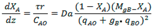
|
(1) |
The boundary conditions of Equation (1) are:
z = 0 XA = 0
z = zmaxi XA = XAi
( i : number of subdivision of the staged feed)
Da= k CAO (Dämkohler number)
r = k CACB, (second order
reaction rate)
τ = VR/Q = VR/(QA0 +
QB0)
MgB = gB*(CB0/CA0)
qA0=QA0/(QA0 + QB0)
qB0=QB0/(QA0 + QB0)
In this study, this differential equation must be solved for three intervals, so one obtain [
5]:
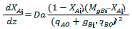 (i=1,2,3) (i=1,2,3) |
(2) |
MgBi = gBi*(CB0/CA0) (i=1,2,3)
0 zmax1 =1/6 gB1=1/3 0 (i=1)
1/6 zmax2 =1/2 gB2=2/3 (i =2)
1/2 zmax3 =1 gB3=1 XA2 < XA < XA3=XAS (i =3) |
|
So, for each interval i, fourth-order Runge-Kutta method was applied to equation (2) in order to get the conversion rate of reactant XAi. In the last interval (in this study, i=3) one can finally obtain the conversion at the reactor exit XAS =XA3.
5. Results and Discussion
5.1. Influence of the Feed Reactants Concentrations (CA0 and CB0) on the Conversion
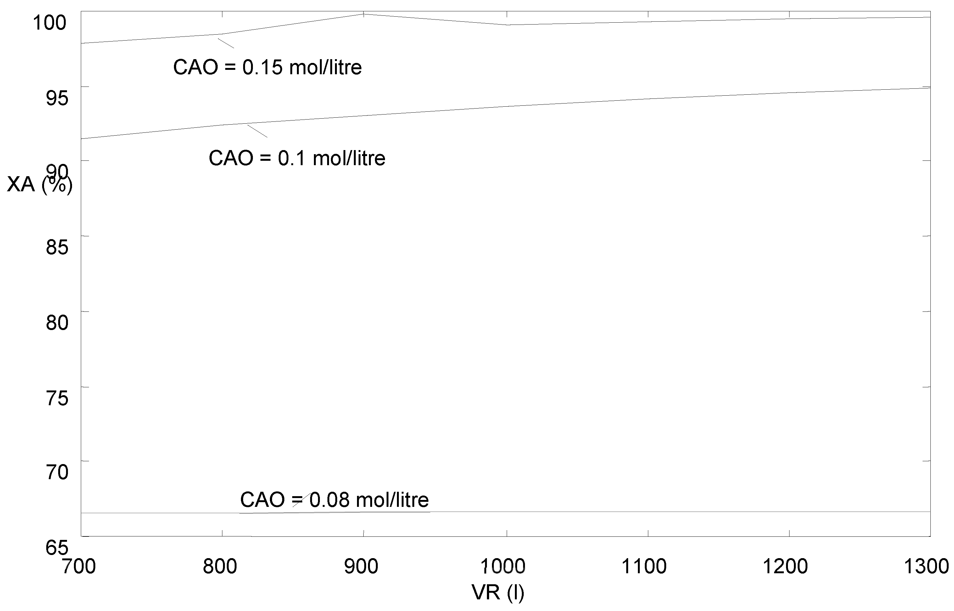
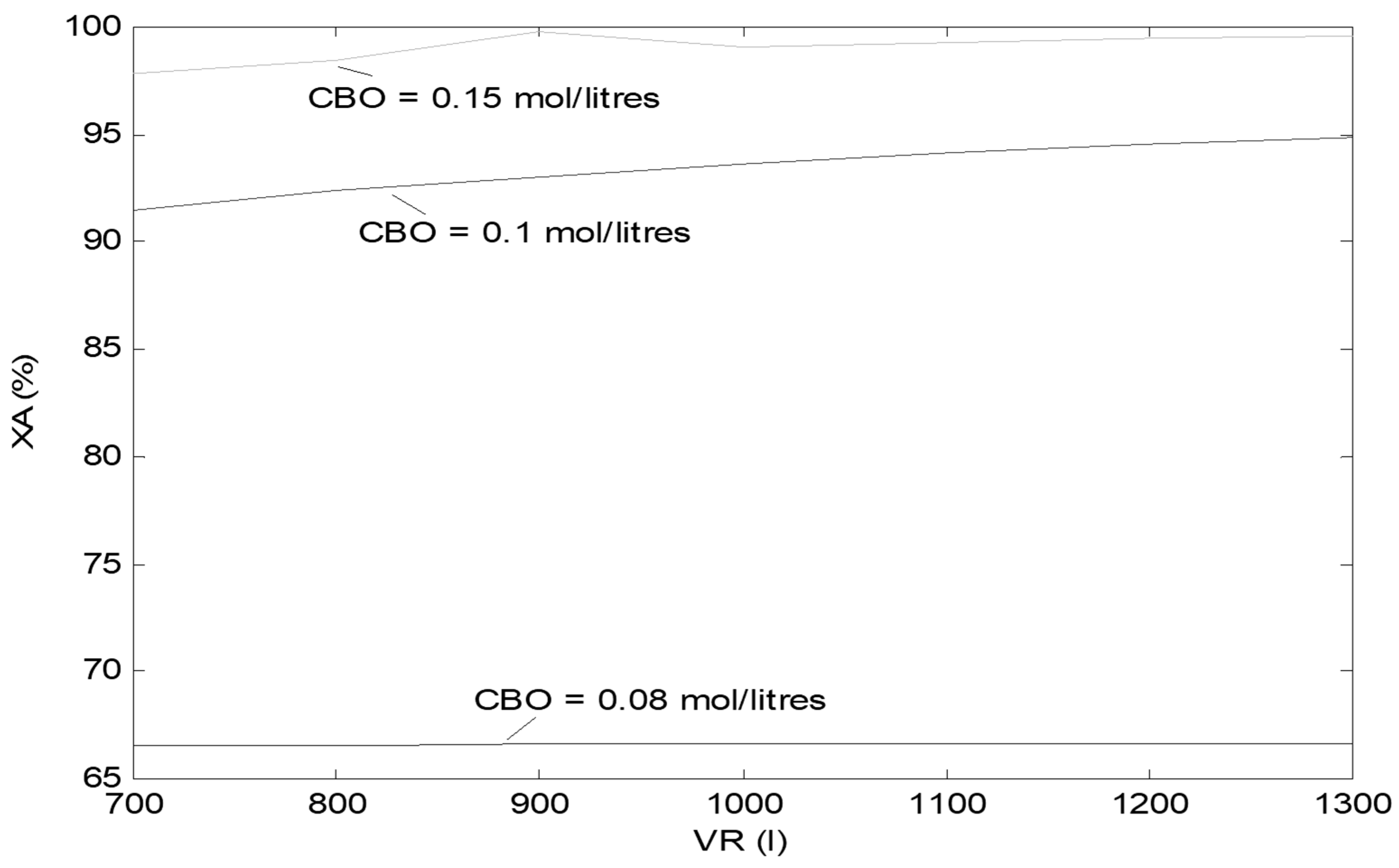
Figure 2 and
Figure 3 show the effect of varying the feed reactants concentrations on the outlet conversion. It can be seen that for a fixed value of volume reactor the conversion is very sensitive to reactants concentrations. For low reactants concentrations values (C
A0 and C
B0 ≤ 0.08 mol/litre), the conversion is low and seems to be independent of the volume reactor. At high values of reactants concentrations values (C
A0 and C
B0 = 0.1 mol/litre), the conversion is high and is dependant of the volume reactor. At very high values of reactants concentrations values (C
A0 and C
B0 ≥ 0.15 mol/litre), the conversion is very high and becomes approximately constant especially at high of the volume reactor.
5.2. Influence of the Volume Flow Rate (Q) on the Outlet Conversion
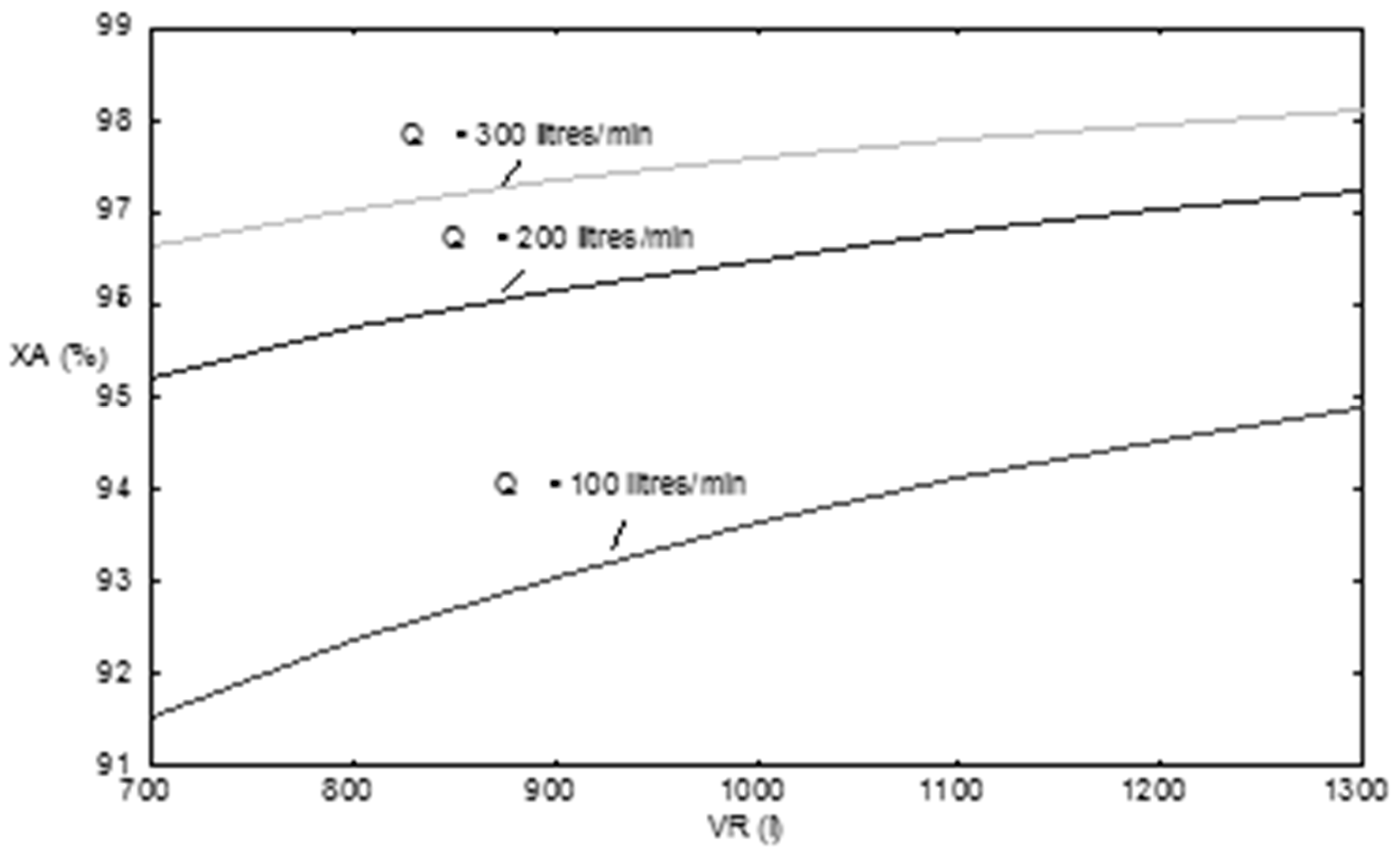
Figure 4 shows the effect of varying the volume flow rate (Q) on the outlet conversion. It can be seen that for a fixed value of volume reactor the conversion is very sensitive to volume flow rate. This last effect is very sensitive for low values of flow rate Q because the curves have tendency to be separated from one another. For low flow rate values (Q ≤ 100 litres/min), the conversion is quite low and seems to be dependent of the volume reactor. At high values of flow rate values (Q ≥ 200 litres/min), the conversion is high and is dependant of the volume reactor. At very high values of flow rate values (Q ≥ 300 litres/min), the conversion is very high and becomes approximately constant especially at high of the volume reactor.
5.3. Influence of Staged Feed Distribution on the Outlet Conversion
Figure 5 shows the effect of varying the staged feed distribution of co-reactant B on the outlet conversion. In this study five repartition of the co-reactant B staged feed were studied in order to get an insight of their influence on the outlet conversion. The number of division of the co-reactant staged feed was chosen to be equal to three (i =3) because this last value is close to one used in the industrial practice. In the program which simulates the studied process, the configuration number of the staged feed and the number of division of the co-reactant staged feed can be easily varied by changing their values. The studied repartitions of the staged feed along the tubular reactor were varied from the wide one to the narrow one (from the top to the bottom in
Figure 5) in order to find which configuration optimizes the outlet conversion.
Table 2 resumes the obtained values of conversion for each studied configuration. It can be noticed from
Table 2 that for the largest repartition of the staged feed, the outlet conversion is equal to 87.43 %, and for the narrowest repartition one, the outlet conversion becomes maximal and equal to 97.60 %. So, it can be concluded that as the repartition of the staged feed becomes more narrow and more close to the inlet of the tubular reactor, the outlet conversion increases and becomes maximal relatively to the other cases.
6. Conclusions
This research highlighted the effects of configuration of the staged feed distribution on the efficiency of a tubular reactor. Three operating parameters were studied, namely: reactant concentrations (CA0, CB0), volume flow rate (Q) and the distribution function of the co-reactant staged feed (gi). The obtained results showed that the outlet conversion increases as the reactant concentrations increase. The conversion is sensitive to the volume flow rate and it increase by increasing this last one. Furthermore, it was found that as the distribution of the co-reactant staged feed becomes narrow and close to the inlet of the tubular reactor, the outlet conversion value increases and becomes maximal comparatively to the other studied configurations. Therefore, the optimal configuration or distribution of the co-reactant staged feed can be determined by simulation using trial methods. In a future study, the effect of temperature on the distribution of co-reactant staged feed tubular reactor will be investigated.
References
- Fogler. H. S. Elements of chemical reaction engineering. Pearson Education. 4th ed., 2006.
- Luyben W L. Chemical reactor design and control, second ed, New Jersey: John Wiley & sons; 2007.
- Bendjaouahdou C, Bendjaouahdou M H (2013) Control of the hot spot temperature in an industrial SO2 converter, Energy Procedia, 36, 428-443.
- Gornay, J., Glaude, P.A.., Billaud, F., Coniglio, L. Experiments and Modeling of Octanoic Acid Pyrolysis in a Plug Flow Reactor, Journal of Analytical and Applied Pyrolysis 146 104767.
- Villermaux J. Génie de la réaction chimique, Tec & Doc-Lavoisier (1993).
- Luyben, W. L. (2001a). Design of cooled tubular reactor systems. Industrial and Engineering Chemistry Research 40 , 5775 /5783.
- Luyben, W. L. (2001b). Effect of design and kinetic parameters on the control of cooled tubular reactor systems. Industrial and Engineer-ing Chemistry Research 40 , 3623 / 3633.
- Modliński, N J. Kordylewski W K,. Jakubiak M P. (2013) Numerical simulation of O3 and NO reacting in a tubular flow reactor, Chem Process Eng, 34(3), 361-373.
|
Disclaimer/Publisher’s Note: The statements, opinions and data contained in all publications are solely those of the individual author(s) and contributor(s) and not of MDPI and/or the editor(s). MDPI and/or the editor(s) disclaim responsibility for any injury to people or property resulting from any ideas, methods, instructions or products referred to in the content. |
© 2024 by the authors. Licensee MDPI, Basel, Switzerland. This article is an open access article distributed under the terms and conditions of the Creative Commons Attribution (CC BY) license (http://creativecommons.org/licenses/by/4.0/).