Submitted:
07 December 2024
Posted:
09 December 2024
You are already at the latest version
Abstract
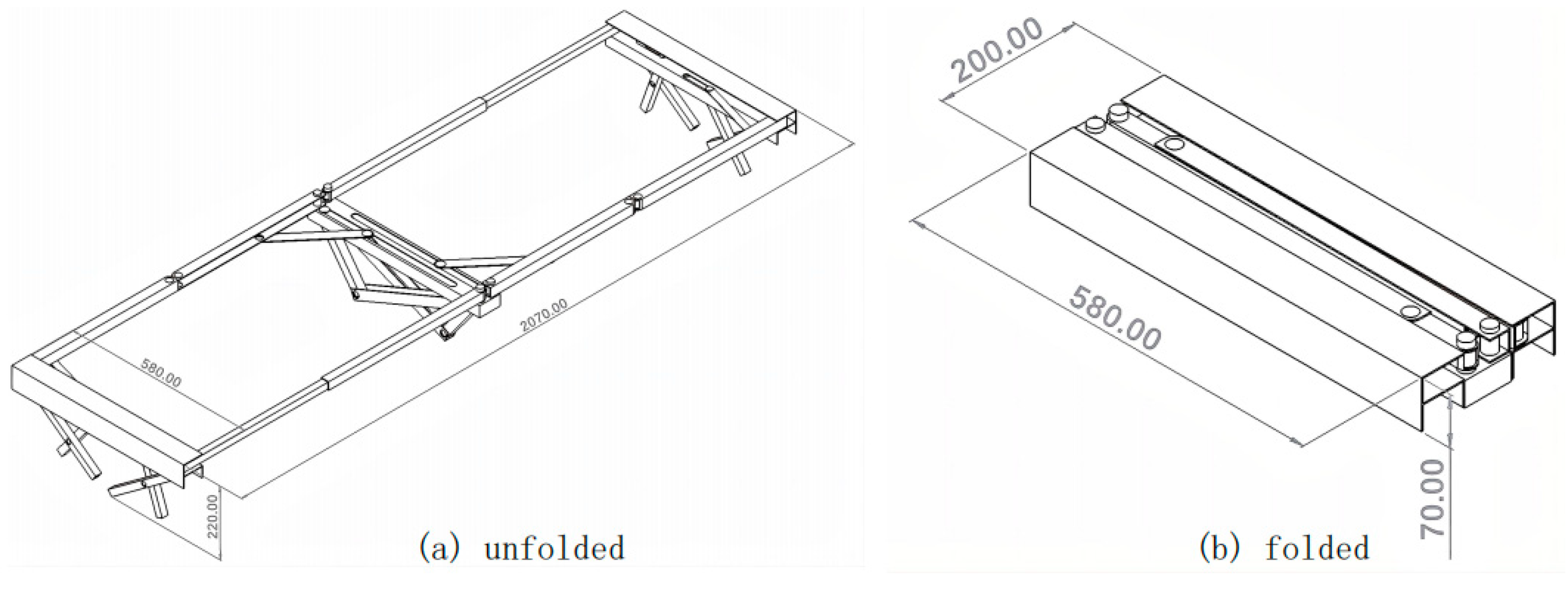
This paper delves into a newly designed folding bed structure to mitigate the limitations in current market offerings. The main body is divided into five sections: introduction, design, analysis, Model display, and conclusion. The first section outlines the common types of folding beds and their limitations and presents the design objectives: portability, ease of assembly, and efficient transportation. In the second part of this paper, a detailed description of the folding bed design is provided, encompassing the design of the entire structure and each substructure. The design prominently employs the crank-slider mechanism, utilizing deformation and combination to achieve rapid deployment. Assembly diagrams and dimension annotations for critical components are also included. In the third part of the paper, a degree-of-freedom analysis and geometric calculation analysis are conducted for each substructure design, which substantiates the design's feasibility. For the analysis of each substructure, corresponding 2D simplified diagrams and plot diagrams are included. The design was modeled in SolidWorks, including modeling each substructure and the overall folding bed. A series of images depicting the folding and unfolding process of these models is presented in the fourth part of this paper. A summary of the overall design is provided in the final section of the article. The folded dimensions of the folding bed are [200*580*70], and the unfolded dimensions are [2070*580*220]. These dimensions roughly meet the design objectives, although some deficiencies still require improvement.
Keywords:
folding bed
; portable camping bed
; slider crank mechanism
1. Introduction
Folding beds, a flexible and versatile form of furniture, play an increasingly important role in modern life. This design lets bedrooms quickly transform into other functional areas, such as the living room or study, thus significantly improving space utilization. Moreover, they can be used not only in smaller spaces that require multiple functions [1,2] but also to meettemporary or urgent needs, such as camping [3] orepidemics [4,5]. In addition, due to their simple and portable design, folding beds also meet the demands of being environmentally friendly and economical.
However, existing folding beds still have some issues, including occupying too much space even when folded, which is shown in Figure 1 [6], and being difficult to carry, which is shown in Figure 2 [7], or requiring complex assembly steps that need to be followed according to instructions to unfold them. To address these challenges, the group designed a folding bed with a small space and a relatively regular shape for easy transport when folded. Furthermore, it can be unfolded simply.
2. Design
2.1. Comprehensive Concept
As shown in Figure 2a,b, many folding bedshave a design with separate frame and bed surfaces, significantly reducing their folded size for improved portability and storage. This folding bed adheres to the same design principles. Square tubes and C-channels were selected for this bed design to achieve a cuboid shape when folded. As shown in Figure 2c, the cross-sectional profiles of the various tube materials used in this folding bed are shown. With proper sizing and folding mechanisms, the square tubes and C-channels can nest within each other, minimizing the stowed volume.
As illustrated in Figure 3, the bed surface frame employs an "M"-shaped deployment mechanism. The rectangular outer framework of the bed is constituted by the assembly of two "M"-shaped deployment units, which exhibit central symmetry. When fully deployed, the folding bed forms a rectangular frame with the missing sides completed using telescoping rods.
Abiding by this design, the whole structure of the folding bed can be partitioned into three substructures, referred to as Substructure 1, Substructure 2, and Substructure 3. Figure 4 shows that Substructure 1 is identical to Substructure 3 due to the central symmetry. The subsequent task involves the detailed design of Substructure 2 and the refinement of Substructures 1&3.
2.2. Main Substructure
2.2.1. Substructure 2
The structure is comprised of two identical slider-crank mechanisms. The crank-slider mechanism exhibits one degree of freedom, with the short rod capable of rotating 360 degrees [9].
Therefore, when the short rod is aligned at 0 or 180 degrees concerning the slide slot, the entire crank-slider mechanism collapses into a straight line (in a 2D model). In practical 3D designs, the rods can be configured as square tubes and C-channels to enable nested storage. For simplicity, Figure 5a illustrates the design in 2D.
The slider-crank mechanism offers the advantage of self-locking when a vertical downward force is applied, causing the slider to lock against the opposing side of the slot (C&F). This design leads to a structure that is both stable and reliable.
In the practical 3D design, each slider requires its dedicated slot. Consequently, the two slider-crank mechanisms cannot coexist in the same plane. To reduce the steps for unfolding the folding bed, the most optimal unfolding method for Substructure 2is to link with the horizontal expansion of the top rectangular frame ("M"-shaped deployment).
Substructure 2 is positionedcentrally on the folding bed and is linked to the rotational movements of Rod A and Rod B, as depicted in Figure 5b. It comprises two identical slider-crank mechanisms, labeled as mechanisms a and b. A linkage bar can be added between the two sliders and Rods A and B to connect the mechanisms and the rods. (as indicated by the red dashed lines in Figure 5b). This setup links the rotation of Rod A to the translation of slider-crank mechanism a and the rotation of Rod B to the translation of slider-crank mechanism b.
The following illustration represents the assembly drawing of the complete Substructure 2, along with critical dimensions for each component:
Figure 6 presents the assembly diagram of Substructure 2, along with annotations for some critical dimensions. Engineering drawings of individual components are included in Appendix 3.
*In the actual modeling data, space has been reserved for part movement, which results in slight discrepancies compared to the computational outcomes.
2.2.2. Substructure 1&3
Substructure 1&3 comprises two identical scissor-like elements (labeled as part A and part B) with a linkage bar that synchronizes their motion. For simplicity, this could be represented in a 2D illustration as Figure 7a.
The whole substructure exhibits one degree of freedom, with specific details provided in the following section of this report.
Each scissor-type element is derived from a crank-slider mechanism. Take part A as an example: extending the primary crank-slider mechanism’s two rods, AC and BC, transforms it into a scissor-like, as illustrated in Figure 7b.
To ensure the mobility of the whole substructure is 1, the two scissor-type elements fold in distinct manners. As illustrated in Figure 7c, in the case of part B, when the slider is moved to the left, the entire element folds directly upward. As for part A, the element folds and rotates simultaneously when the slider is moved to the left.
The two scissor-like elements cannot be identical due to their differing folding mechanisms, as both sliders move the same distance during the folding and unfolding process. Part B, as depicted in Figure 7c, originates from a larger crank-slider mechanism. Although the two scissor-type elements are not identical, through the calculation and design of each rod, the center of gravity of the bed could be positioned over the center of the support area perfectly, providing reliable and stable support. (The calculating process will be provided in subsequent sections)
Similarly, to simplify the setup process of the foldingbed, substructure 1&3 could also be combined with the horizontal expansion of the top rectangular frame (“M”-shaped deployment) by adding a connecting rod between the slider and the horizontal rotating rod.
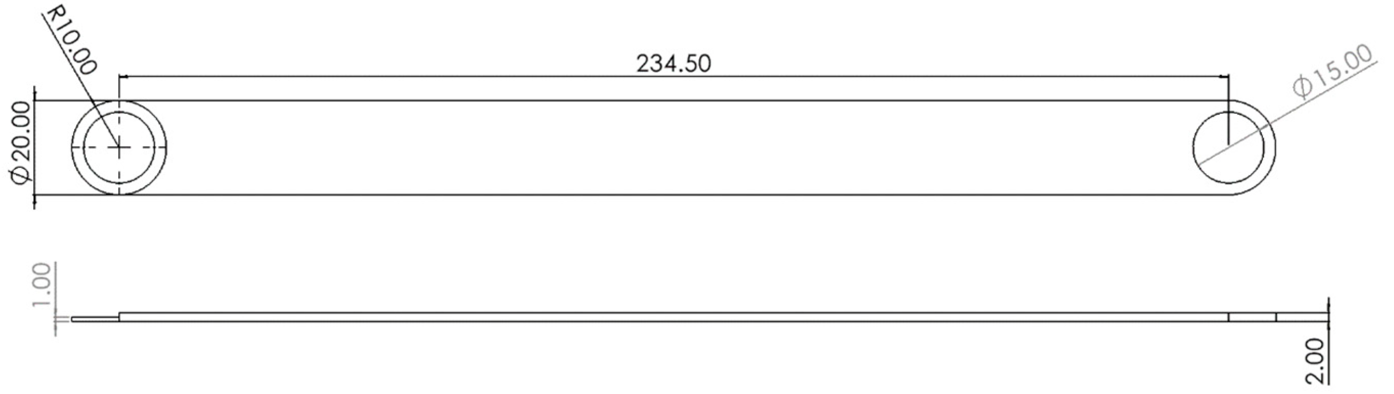
Figure 8 presents the complete assembly drawing of the substructure 1&3, including critical dimensional annotations for critical components:
(Engineering drawings of individual components are included in Appendix 3.)
*In the actual modeling data, space has been reserved for part movement, which results in slight discrepancies compared to the computational outcomes.
2.3. Details Design
2.3.1. The Telescopic Pole Mechanisms
Some cylindric poles are usually tapered and comprise several partsthat can slip into each other to fold and deploy. These kinds of poles are called telescoperods. It is essential in our design as it can serve functions like saving space, connecting, and supporting the whole structure. However, designing a pole structure with the lightest weight within given boundary conditionsbecomes a big problem.M. Dicleli and his groups discovered a computer program called ODAPS that can automatically design the most suitable telescopic by entering the input data [10]. So, with the front pole segment at 49cm and the rear pole segment at 53cm, the group can finally design a telescopic with the lightest weight and optimal stiffness and strength.
2.3.2. The Joints
The whole structure can be divided into two kinds of joints. The first type linkstwo horizontal bars (“M”-shaped deployment). The second type can only deploy around 90°.
3. Main Sub Structure Analysis
3.1. Degrees of Freedom
3.1.2. Substructure 2
As shown in Figure 11a, substructure 2 comprises two identical 3D crank-slider mechanisms. Therefore, it could take only half of substructure 2 to analyze for simplicity, as the other side is symmetrical.
Figure 11b illustrates half of substructure 2. For a spatial mechanism (3D), each rigid link has 6 DOF, thus applying 3DKutzbach Formula [13]:
From the figure, it can be observed that:
Each joint (joints C and D) has 1 degree of freedom (rotation) for the long slider CD. Since these two joints are located on the same slider, they share an additional degree of freedom (move along the slot). Therefore ;
Substituting the data in the formula, the Mobility of substructure 2 is 1.
3.1.3. Substructure 1&3
Given that the scissor-like element in Substructure 1&3 is derived from a crank-slider mechanism, when analyzing the degrees of freedom, it can be simplified as a crank-slider mechanism, as shown in Figure 12. For a plane mechanism (2D), each rigid link has 3 DOF, thus applying 2DKutzbach Formula [13]:
From the figure, it can be observed that:
Similarly, joints C and D are located on the same linkage bar. Therefore, the movement of C and D is connected, ;
Substituting the data in the formula, the Mobility of substructure 1&3 is 1.
3.2. Computational Analysis
3.2.1. Substructure 2
For substructure 2, Vector methods were used foranalysis. Mechanism 1 was abstracted into a simplified form, as shown in Figure 13, with corresponding symbols labeled. The final formula is detailed in Appendix 1.1.
The bed panel width determines the length of c as 50 cm, and the angle is constant at 180°.To ensure stability, the length of a significantly exceeds b, as shown in Equation 3.
When deployed, the bed’s overall height is set to 16 cm. To ensure its complete folding, BC must fully retract into AB, and the length of AB and BC must be less than the bed panels width. So, the detailed formula can be simplified into following equations:
The system of equations consists of two equations with four unknowns, resultingin the design of a as 41.2 cm and b as 20 cm. By controlling the length of c as the input parameter and using the overall height h of the mechanism as the output, the movement of the mechanism could be determined. As the Plot of motion shown in Figure 14, the overall height h first increases and then decreases to zero as c decreases from 50cm to 21.2cm, which shows that mechanism 1 can fold and unfold completely.
Mechanism 2 was also abstracted into a simplified structure, which is shown in Figure 15, with final equations in Appendix 1.2.
When fully extended, the angle is 90° and the angle remains 0°. Thus, this set of equations can be further simplified into the following system of equations:
The requirements include structural stability and full folding capability. Therefore, the a is designed as 18.3, b as 24.9, and the initial length of c as 16.9 cm, which includes a 2.5 cm gap length and 14.4 cm linkage length. With the length of c as the input parameter and as the output parameter, the movement plot of the mechanism can be shown in Figure 16.
From the initial fully deployed state, gradually increases from 90°to 180°as the length of c increases, proving that the mechanism can be fully folded. Further analysis reveals that with the length c from mechanism 1 changing from 50cm to 21.2cm, the length c from mechanism 2 changing from 16.9cm to 43.2cm, proving that these two mechanisms can fold and deployable simultaneously.
3.2.2. Substructure 1&3
Vector methods were applied for analysis structures 1 and 3, and a simplified structure was abstracted in Figure 17. This led to the following formulas, shown in Appendix 1.3.
Angles and are constant at 180°. For angle and the angle are always 360°. Consequently, the complex formulas can be simplified into the following system of equations:
Requirements include maintaining16 cm height, equal distances between support points for stability, and lengths for equal slides and connecting bar . The group designed as 16 cm, as 12 cm, c as 20 cm, and as 12 cm, with as 16 cm. Based on the geometric relationships of the structure, the group can formulate the following supplementary equations:
The above system has 16 equations with 20 unknowns. Calculations resulted in as 7.69 cm, as 10.25 cm, the length h as 12.31 cm, and equal slide length as 8 cm. The length of c serves as the control input parameter, related to the length of h. The angles and serve as the output variables, indicating the mechanism's complete folding capability, which is shown in Figure 18a and Figure 19b. Further analysis reveals that starting from the initial fully deployed state when the length of c increases from 20cm to 28cm, angle θ1 gradually increases to 360°, while angle θ7 gradually decreases to 180°. This confirms that the mechanism can do the complete folding.
4. Prototyping and Model display
The following section presents the folding sequence diagram of the folding bed. (SolidWorks 3D model)
4.1. Main Sub Structure
4.1.2. Structure 2
Based on the conclusions drawn from the preceding computational analysis, the model of Substructure 2 was built using SolidWorks software.
When transitioning from 2D to 3D design, it’s important to consider clearance distances, such as the required space between the slot end and the top joint.
Figure 19 illustrates the deployment process of Substructure 2 from different perspectives.
4.1.3. Structure 1&3
Following the computational analysis and subsequent adjustments during the modeling process, the determined lengths of the bottom support rods for Substructure 1&3 are as follows: (mm)
Figure 20 illustrates the deployment process of Substructure 1&3 from different perspectives.
4.1.4. Overall Structure
5. Conclusion
In conclusion, this report discusses the design of a new portable folding bed frame that combines the advantages of accessible transport and quick setup. The bed frame folds into a regular rectangular shape, significantly reducing transportation costs. As shown in Figure 23, the dimensions of the bed frame before and after folding are:
This folding bed design primarily involves combining and modifying crank-slider mechanisms while also replacing common tubes with square-cross-section tubes to achieve a regular shape when folded. It can be utilized in various situations, such as emergency relief supplies for disaster response or equipment for outdoor hiking.
However, the design still needs improvement. Currently, setting up the bed frame still requires three steps: pulling out the top frame and then inserting each of the two telescoping rods into their respective positions. Additionally, in practical use, the top rectangular frame does not exhibit a single degree of freedom during both deployment and folding.
Consequently, the nextsteps entail refining the folding bed design. The objective is to achieve a singular degree of freedom for the folding and unfolding mechanism of the top rectangular frame by incorporating as few connecting rods as possible. Furthermore, thefinal aim is to integrate the two telescoping rods into the deployment mechanism of the top frame to facilitate a one-touch setup.
Appendices
1.1. The Mechanism 1 Formula:
1.2. The Mechanism 2 Formula:
1.3. The Structure 1 and 3 Formula:
2.1. The Code of c vs h:
clc
a=0:0.1:28.8;
b=((50-a).*(50-a)+41.2*41.2-20*20)./(2.*(50-a).*41.2);
c=sqrt(1-(b.*b));
theta1=asind(c);
theta11=360-theta1;
h=41.2.*sin(theta1/180*pi);
d=50-a
plot(d,h);
xlabel('c'),ylabel('h'),title('The plot of c vs h');
2.2. The Code of c vs θ1:
clc
x=0:0.1:28.8;
c=14.65+x
b=24.9;a=18.3;
ctheta1=(a*a+c.*c-b*b)./(2*a.*c);
theta1=acosd(ctheta1);
theta11=180-theta1;
plot(c,theta11);
xlabel('c');ylabel('θ1');title('The plot of c vs θ1 ')
2.3. The Code of c vs θ1& c vs θ4:
clc
x=0:0.1:8;
ctheta1=(16*16+(20+x).*(20+x)-12*12)./(2*16*(20+x));
theta1=acosd(ctheta1);
ctheta4=((15.52-x).*(15.52-x)+6.55*6.55-14.07*14.07)./(2.*(15.52-x)*6.55);
theta4=acosd(ctheta4);
figure;
plot(20+x,360-theta1);
xlabel('c');ylabel('θ1');title('The plot of c vs θ1');
hold on
figure;
plot(20+x,360-theta4);
xlabel('c');ylabel('θ4');title('The plot of c vs θ4');
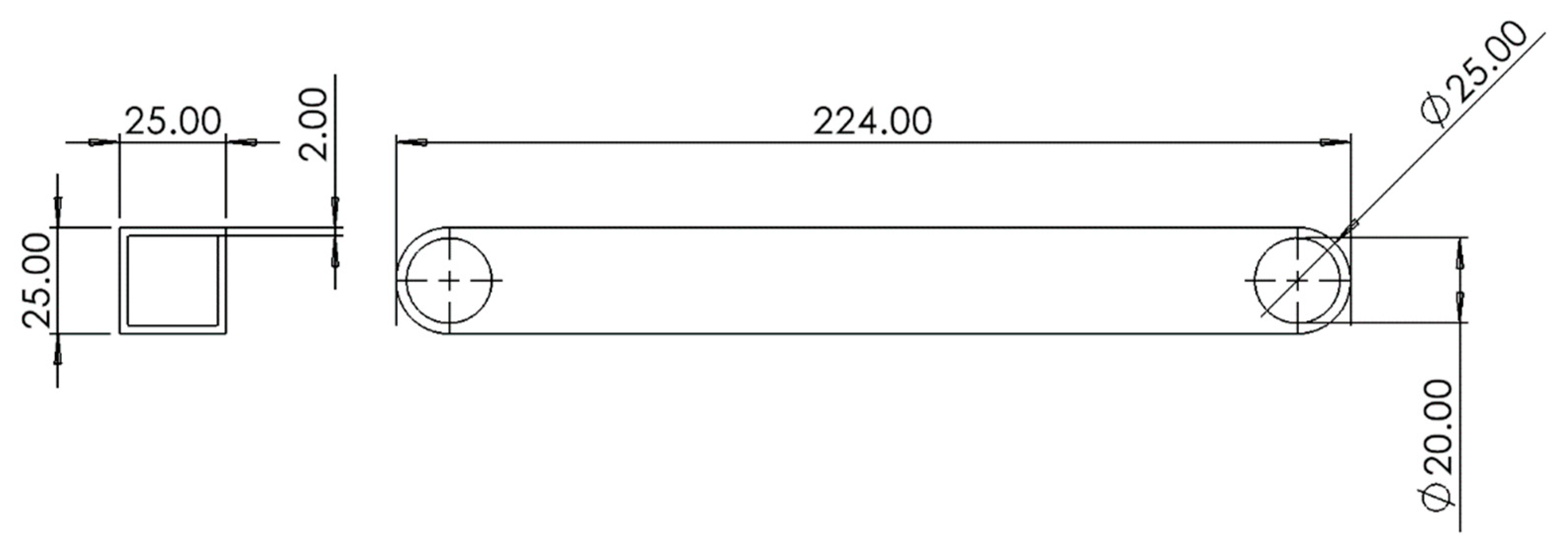
3.1. Engineering Drawings for Substructure 2 Components
Figure 24.
Top main rod.
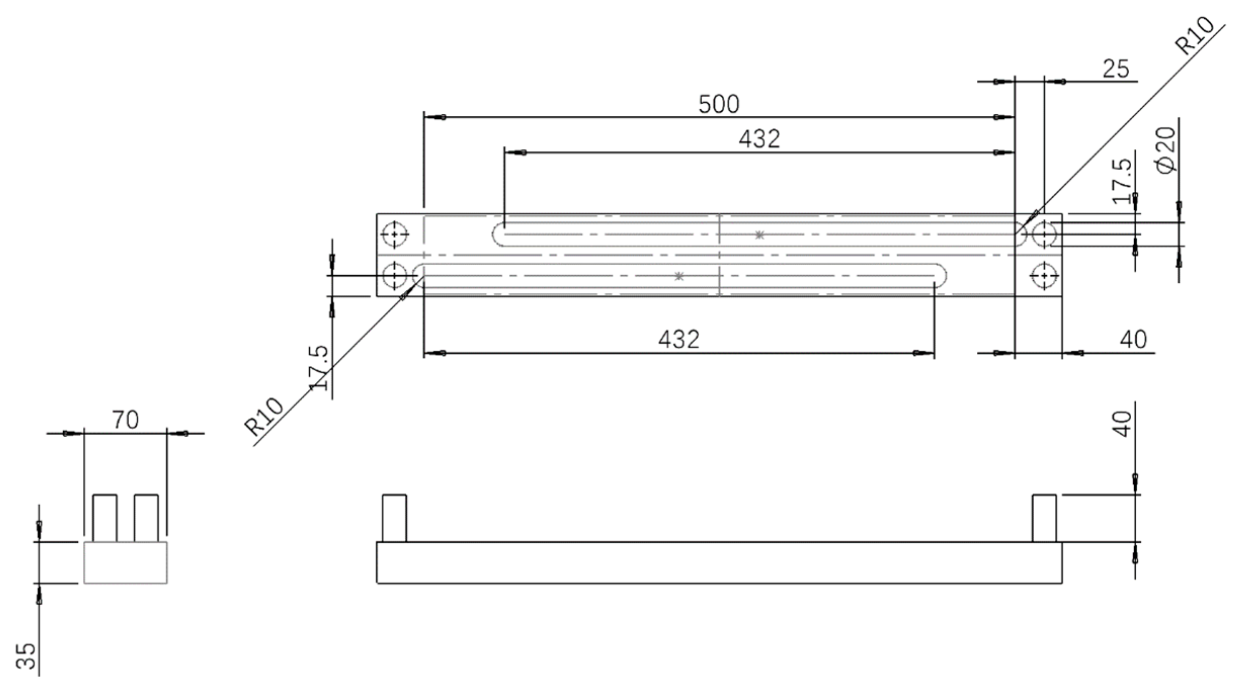
Figure 25.
Long slider.
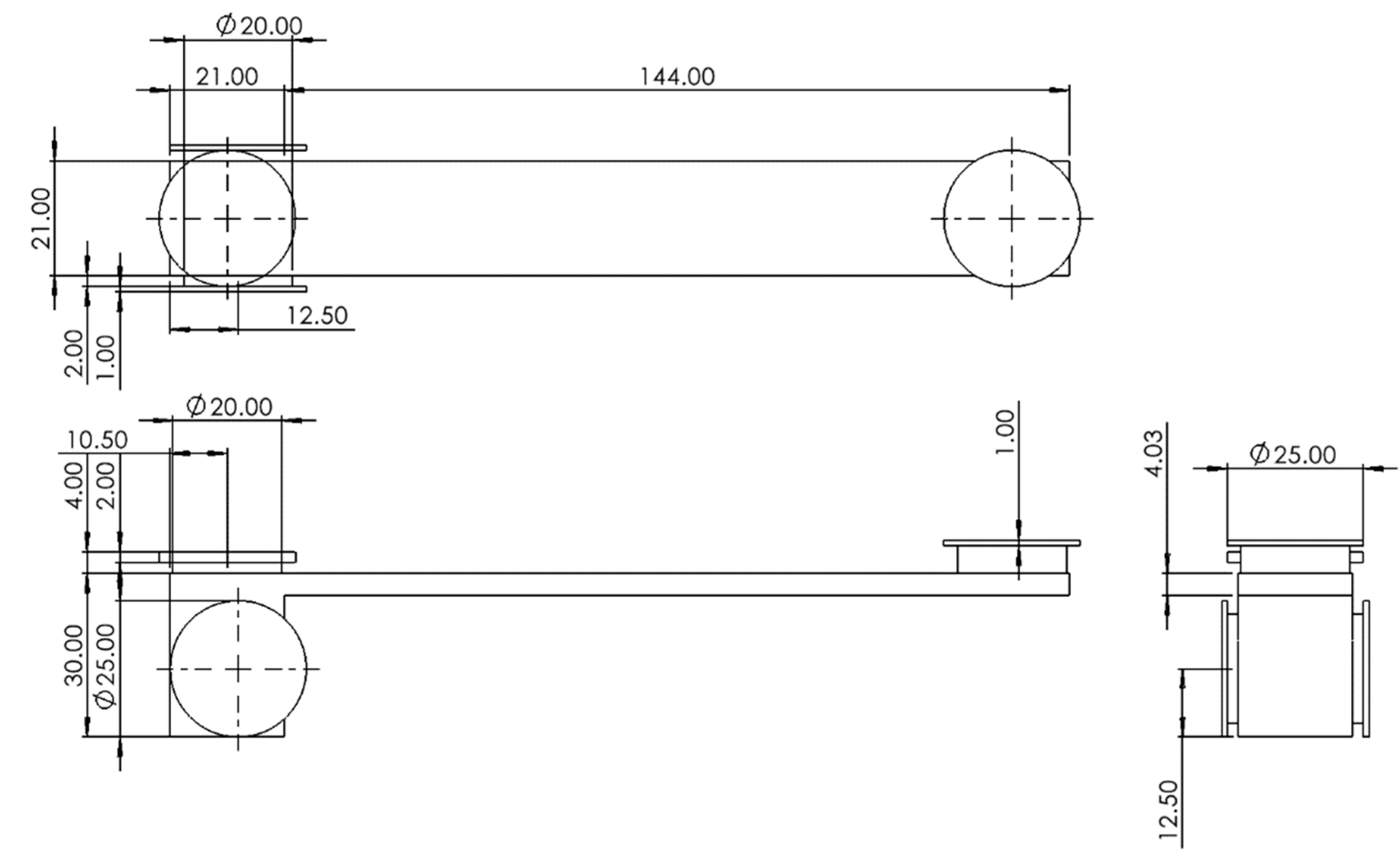
Figure 26.
Long rod.
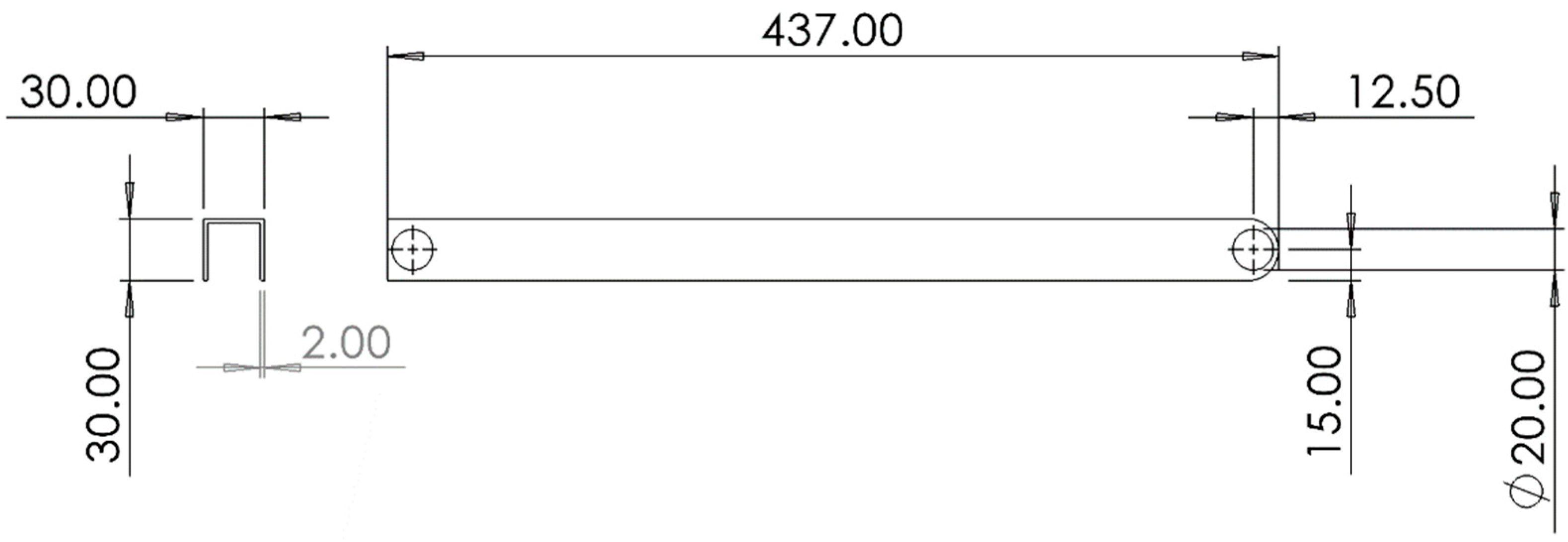
Figure 27.
M-shape deployment rod A.
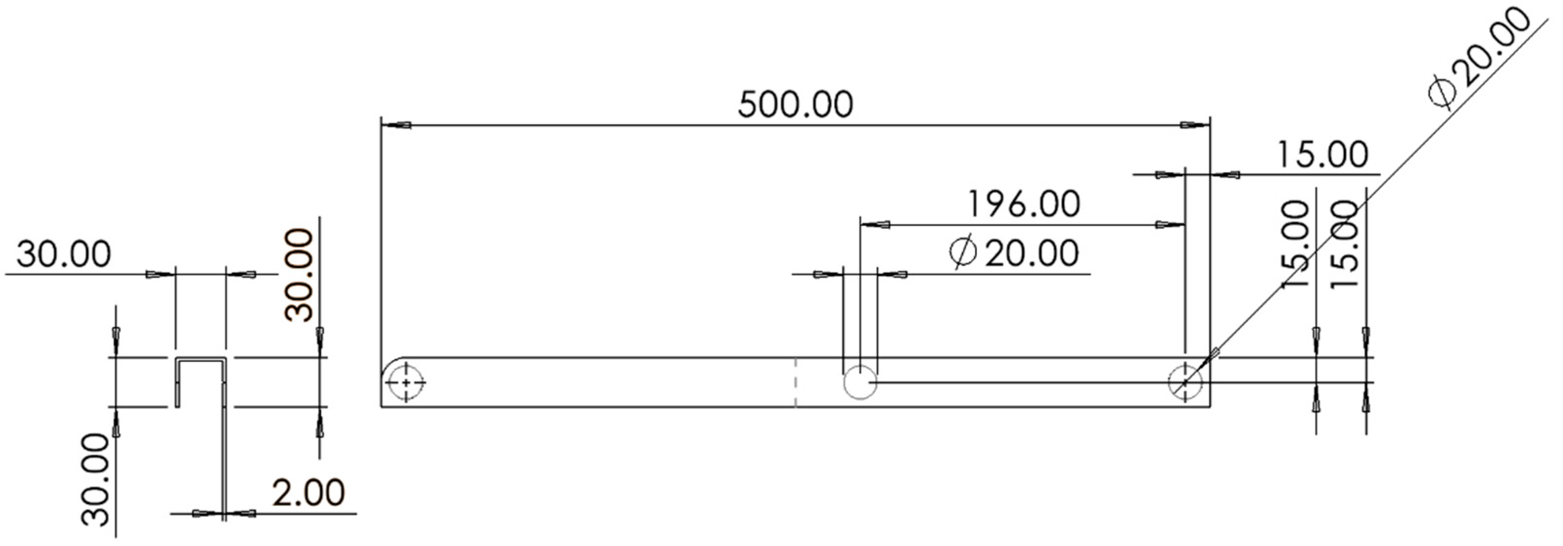
Figure 28.
Linkage bar.
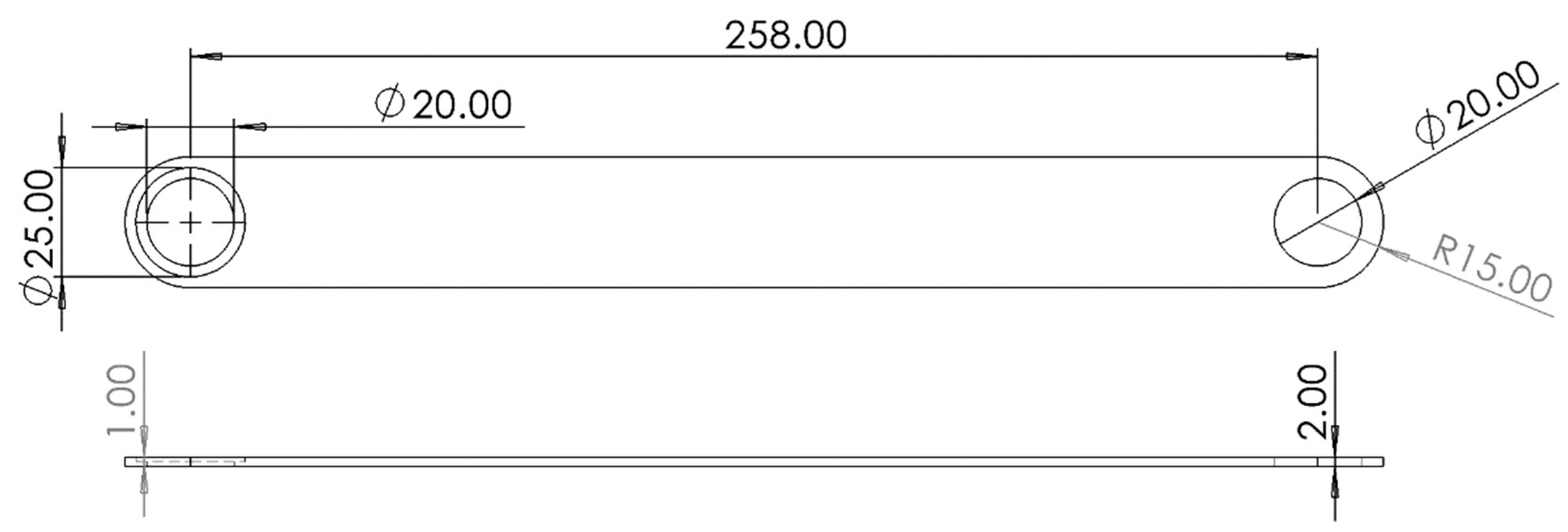
Figure 29.
Short rod.
3.2. Engineering Drawings for Substructure 1&3 Components
Figure 30.
Slider and M-shape spreading tube.
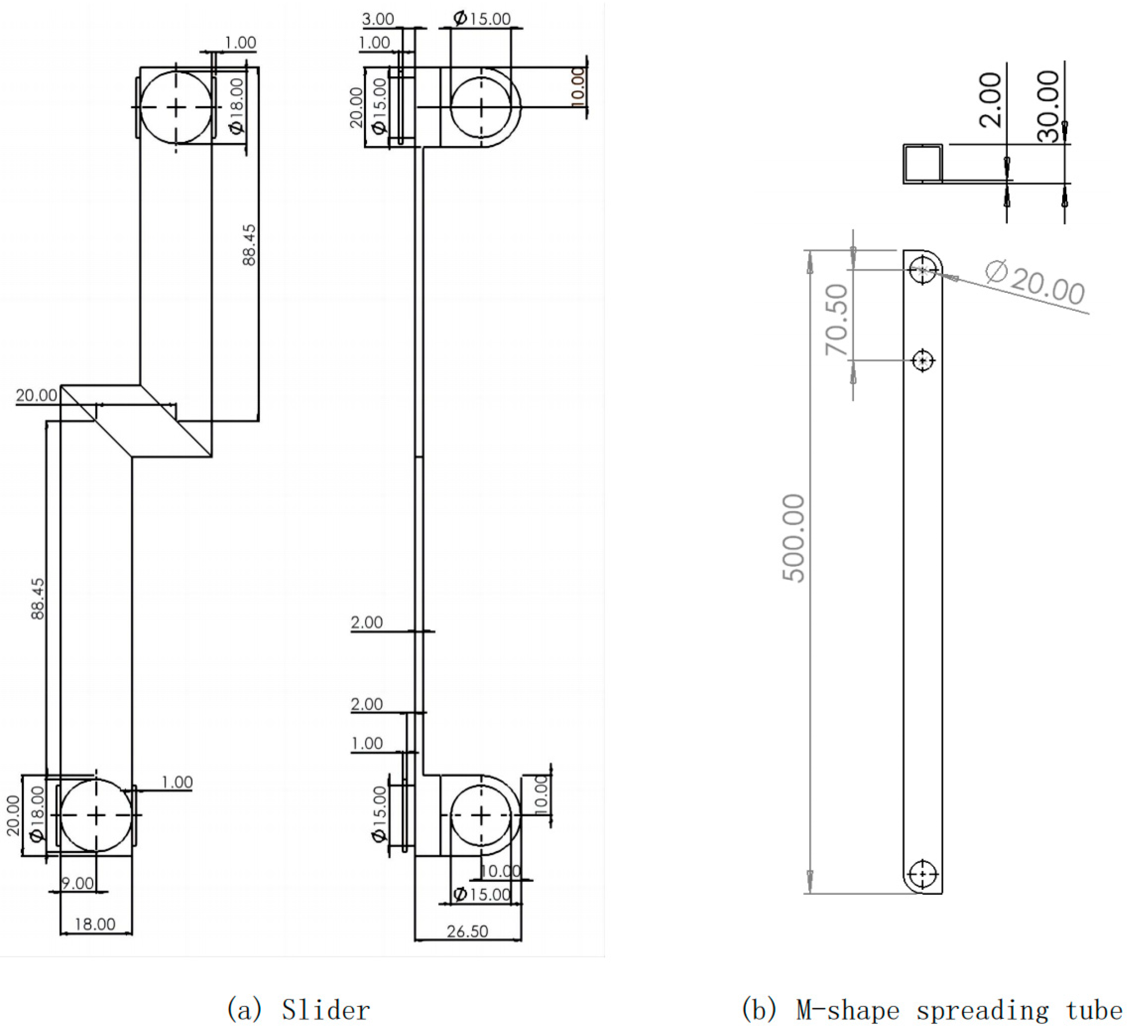
Figure 31.
Figure 31. Rod A to D.
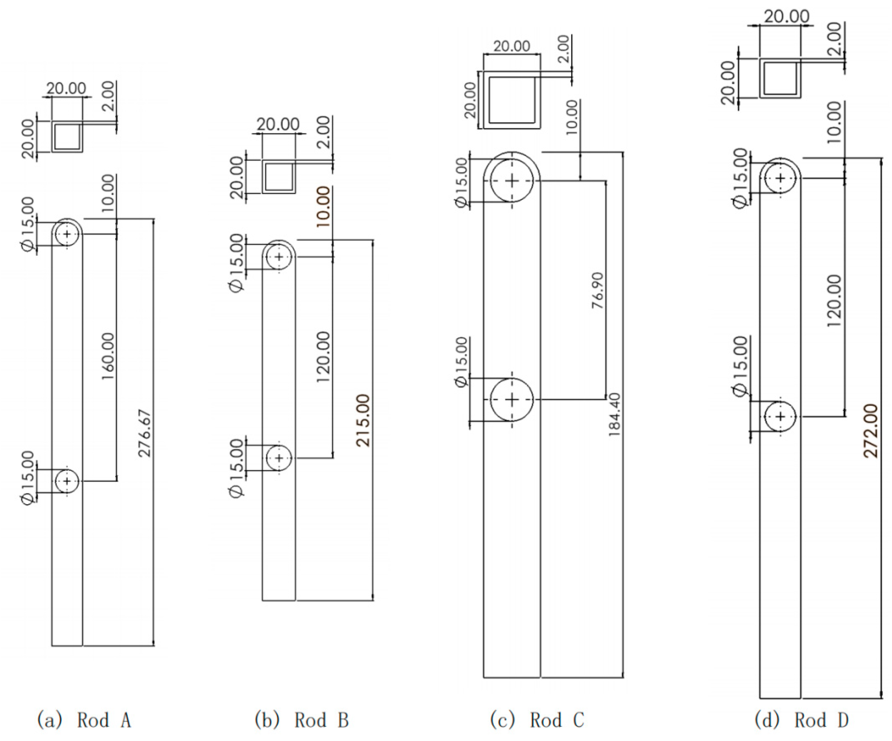
Figure 32.
Top rod
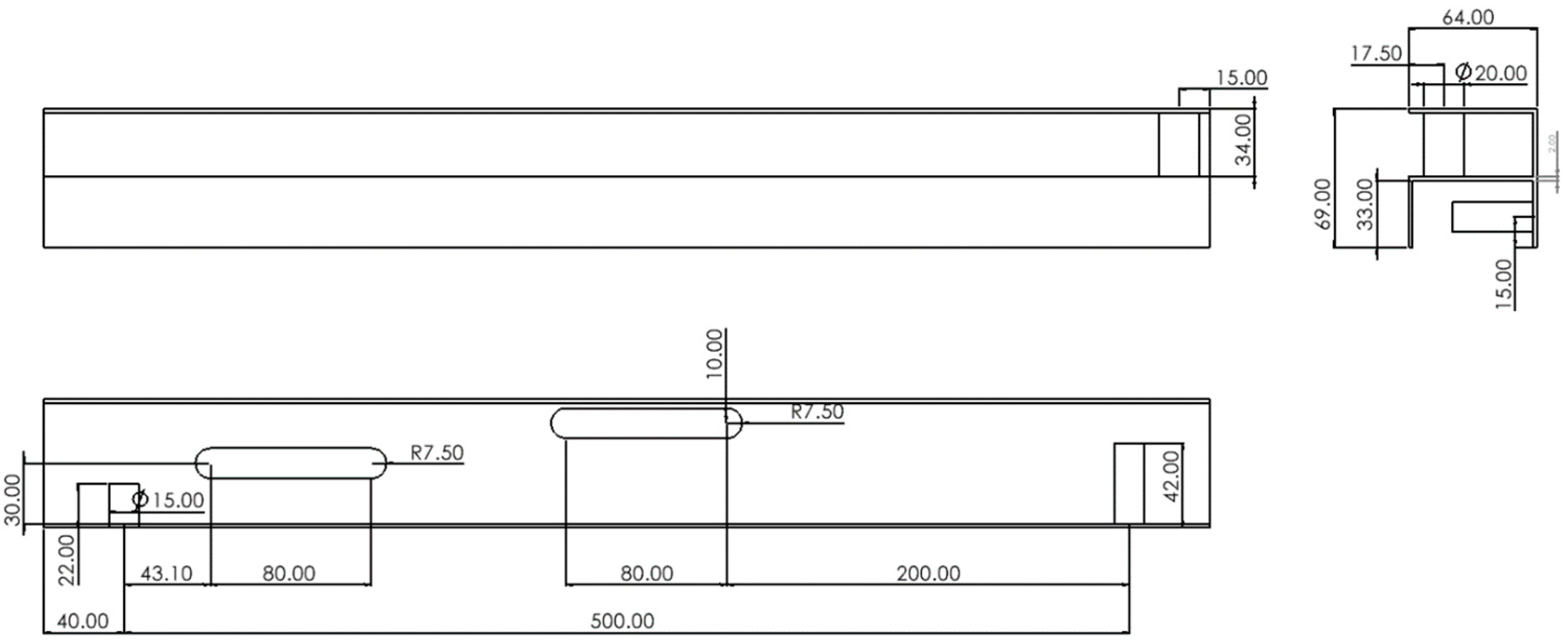
Figure 33.
Linkage bar.
References
- Lu, W.; Zhou, M.; Feng, Y. Research and development of folding bathing bed for the elderly driven by civil water. 2021 3rd International Conference on Artificial Intelligence and Advanced Manufacture; 2021; pp. 2370–2373. [Google Scholar]
- Gang, L.; Li, J.; Rong, Z. Design and Development of Portable Folding Baby Bed. Applied Mechanics and Materials 2013, 65–68. [Google Scholar]
- Zhen, J.; Wan, Y.; Chang, J.; Jian, Y.; Sheng, J.; Xiao, J.; Feng, T. Development of the Portable Field First-Aid Diagnosis Bed. Applied Mechanics and Materials 2014, 914–917. [Google Scholar]
- Laely, M.; Laela Nur, F.; Glenn, H.; Farid, T. Foldable Bed Design Concept for COVID-19 Patient: A Machine Design Case Study. ASEAN Journal of Science and Engineering 2021, 113–126. [Google Scholar]
- Shao, H.; Poh, K. Synthesisation of design features for multifunctional stretcher concepts. Journal of Medical Engineering & Technology 2021, 145–157. [Google Scholar]
- Zhang, J. Folding bed. CN308774308S. Patentstar search. 2024. Available online: https://www.patentstar.com.cn/Search/Detail?ANE=7AFA5CDA9HHH8AEA9GEE8BHA5BEA4AAA9IDFBFEA5DAA5EBA.
- Liu, Y.; Qian, X.J. Folding bed. CN220832466(U). Espacenet Patent search. Espacenet - Bibliographic data. 2024. [Google Scholar]
- Li, X. Outdoor camping camp bed. CN220587891 (U). Espacenet Patent search. Espacenet-Bibliographic data 2024. [Google Scholar]
- D’Angelo, A., Jr. Slider Crank Mechanisms. Dynamics and Mechanisms Design for Technology Students. Synthesis Lectures on Mechanical Engineering; Springer: Cham, 2024. [Google Scholar] [CrossRef]
- Dicleli, M. Computer-aided optimum design of steel tubular telescopic pole structures. Computers & Structures 1997, 961–973. [Google Scholar]
- Wang, Wei; CN, Jiangsu. ADJUSTABLE BED WITH FOLDING MECHANISM. US 11,317,729 B2. Field of Classification Search. 2022. [Google Scholar]
- Xu, J. One kind of Folding bed connection. CN110623464A. Patentstar search. 2024. Available online: https://www.patentstar.com.cn/Search/Detail?ANE=9HGG9IFE9EHD9HAH9HDC9CIC9FHE6FAA9GDCBGIA8FAA9CGE.
- KUTZBACH, K. Einzelfragenaus dem gebiet der maschinenteile[J]. Zeitschrift der Verein Deutscher Ingenieur 1933, 77, 1 168. [Google Scholar]
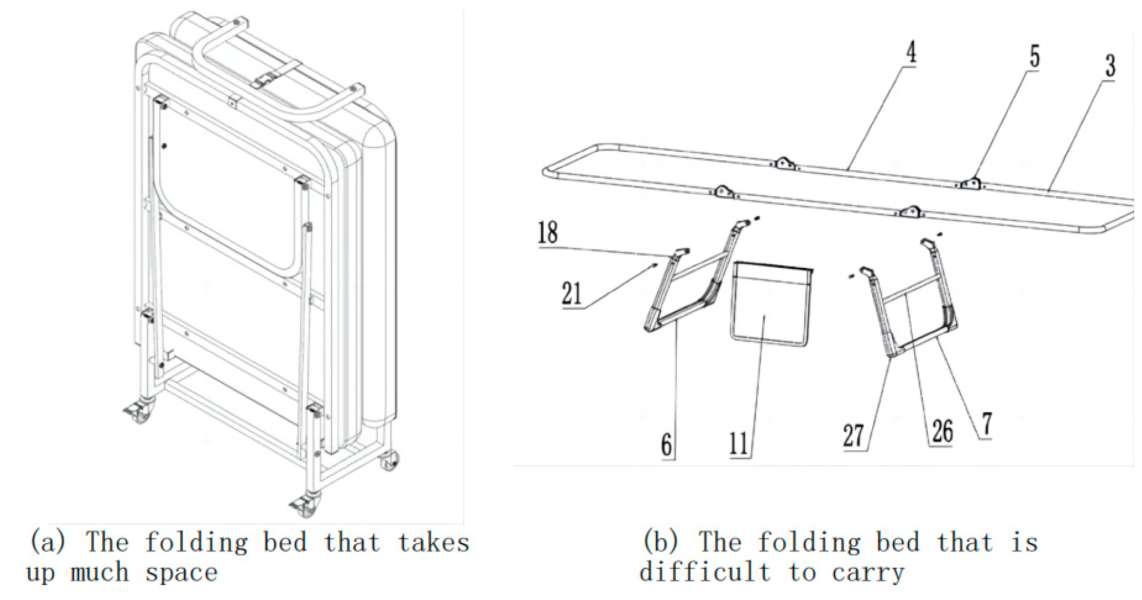
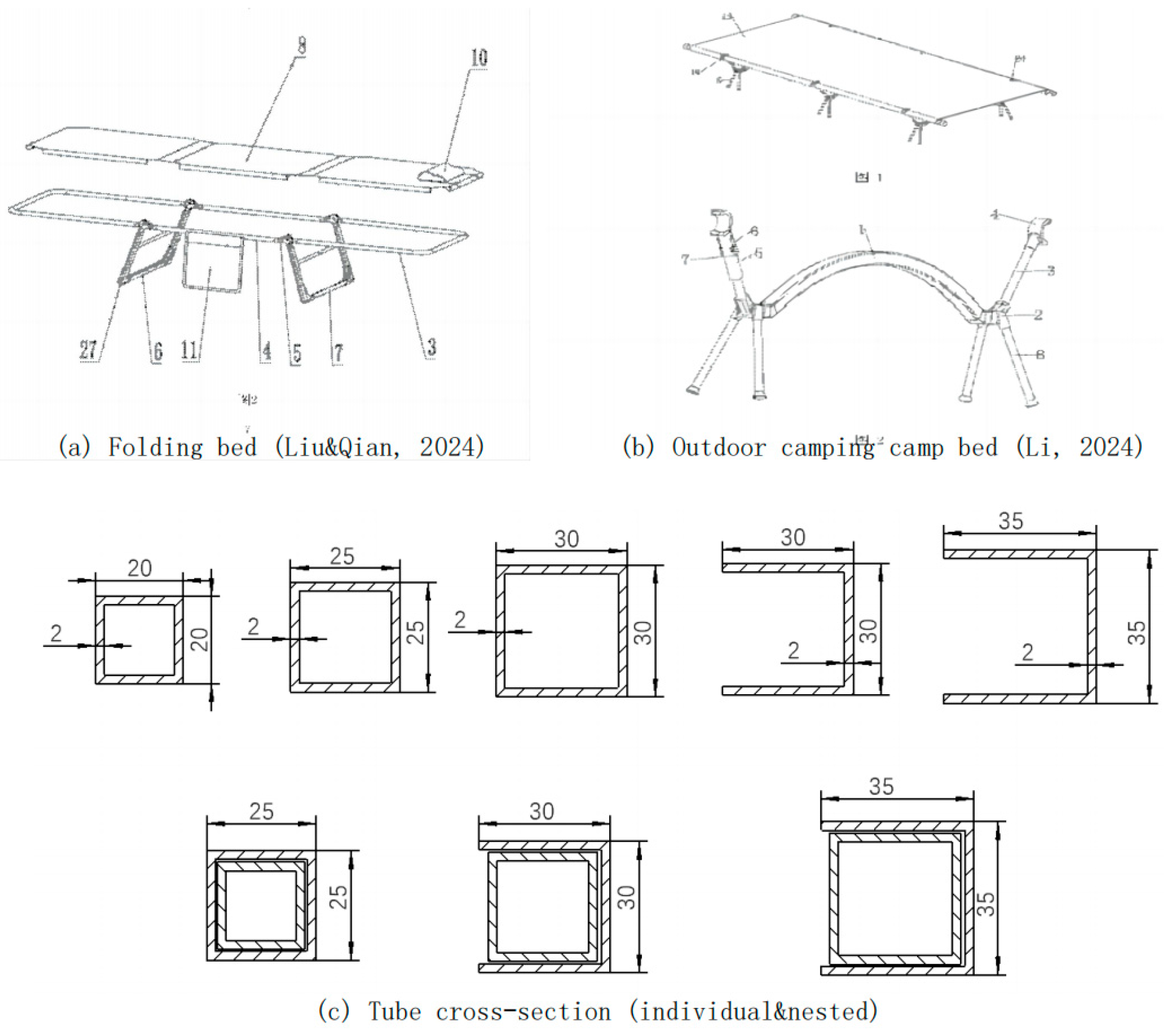
Figure 3.
Deployment process of the rectangular outer framework.
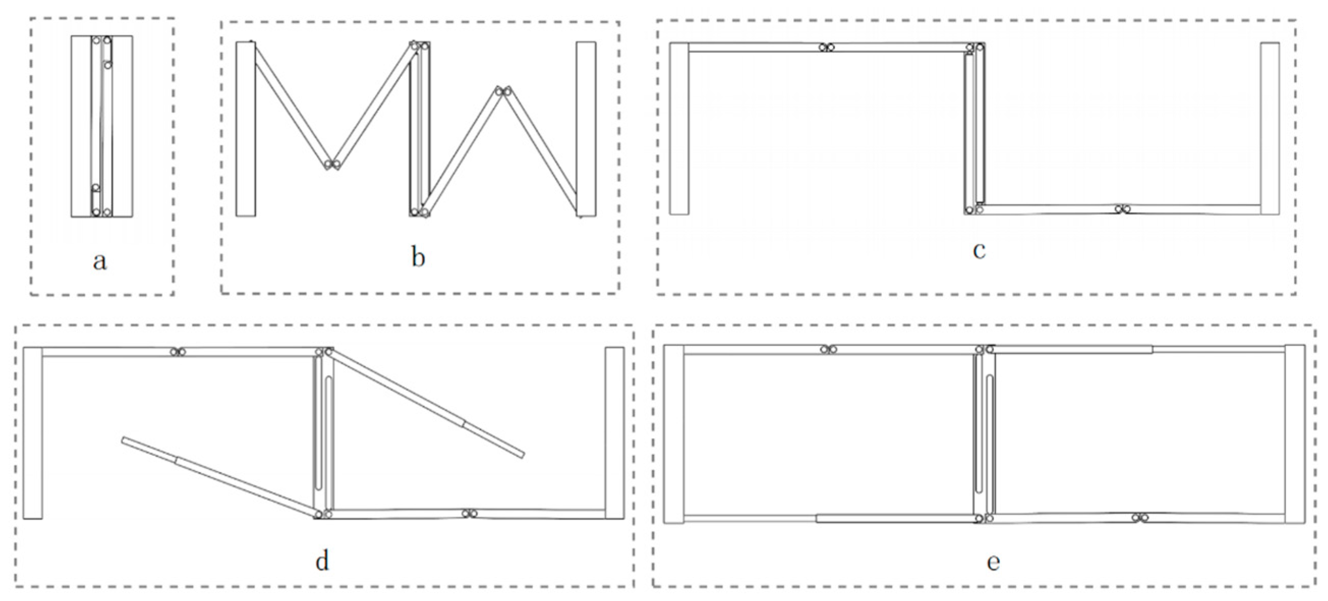
Figure 4.
The overview design figure.
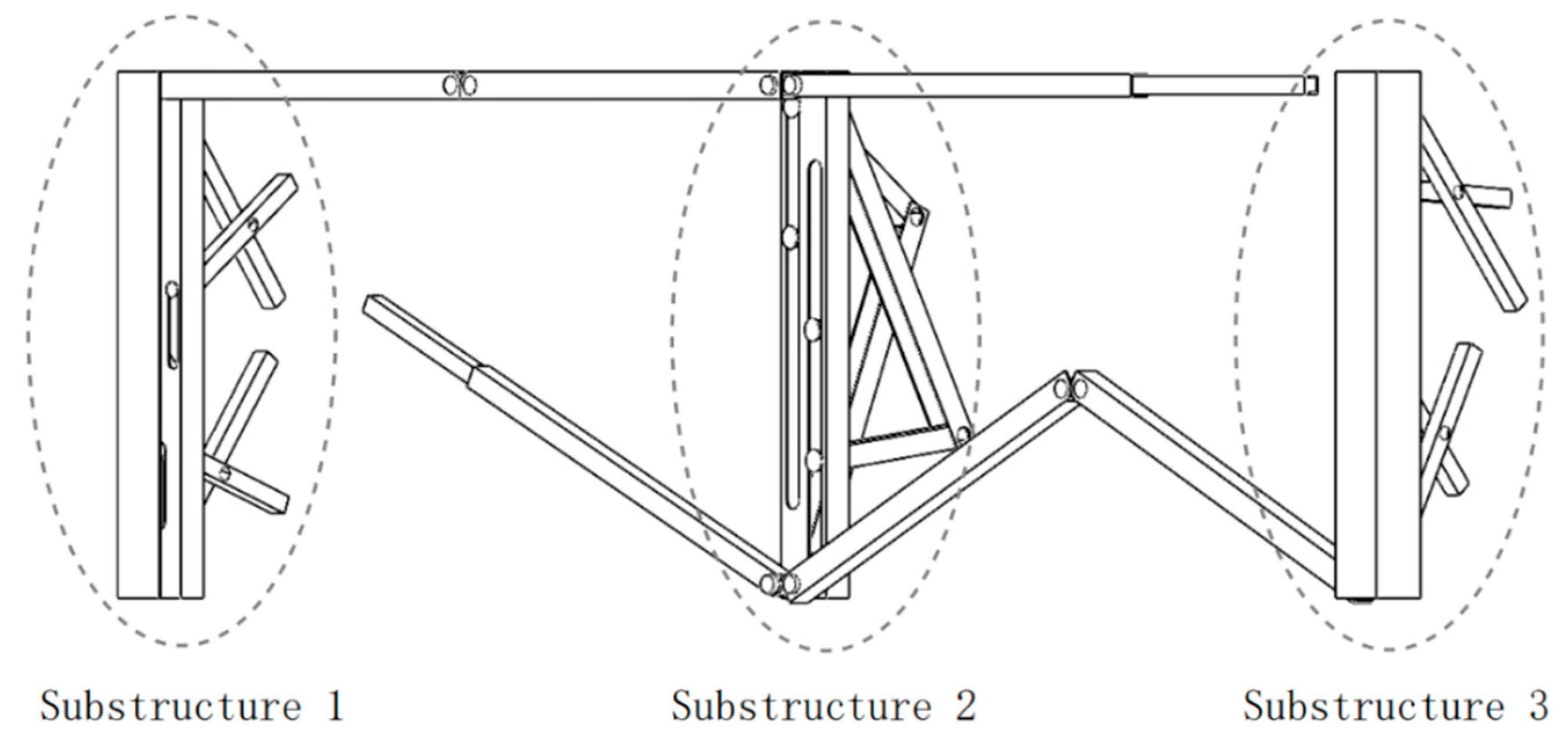
Figure 5.
Design of substructure 2.
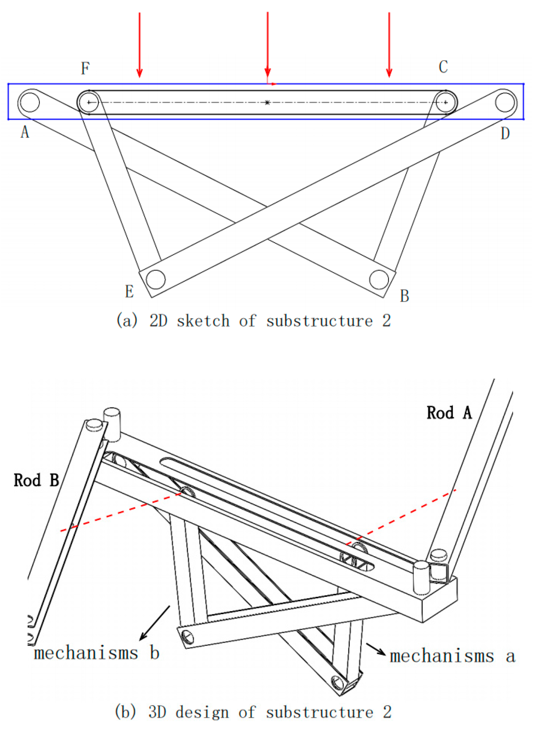
Figure 6.
Engineering drawing for Substructure 2.
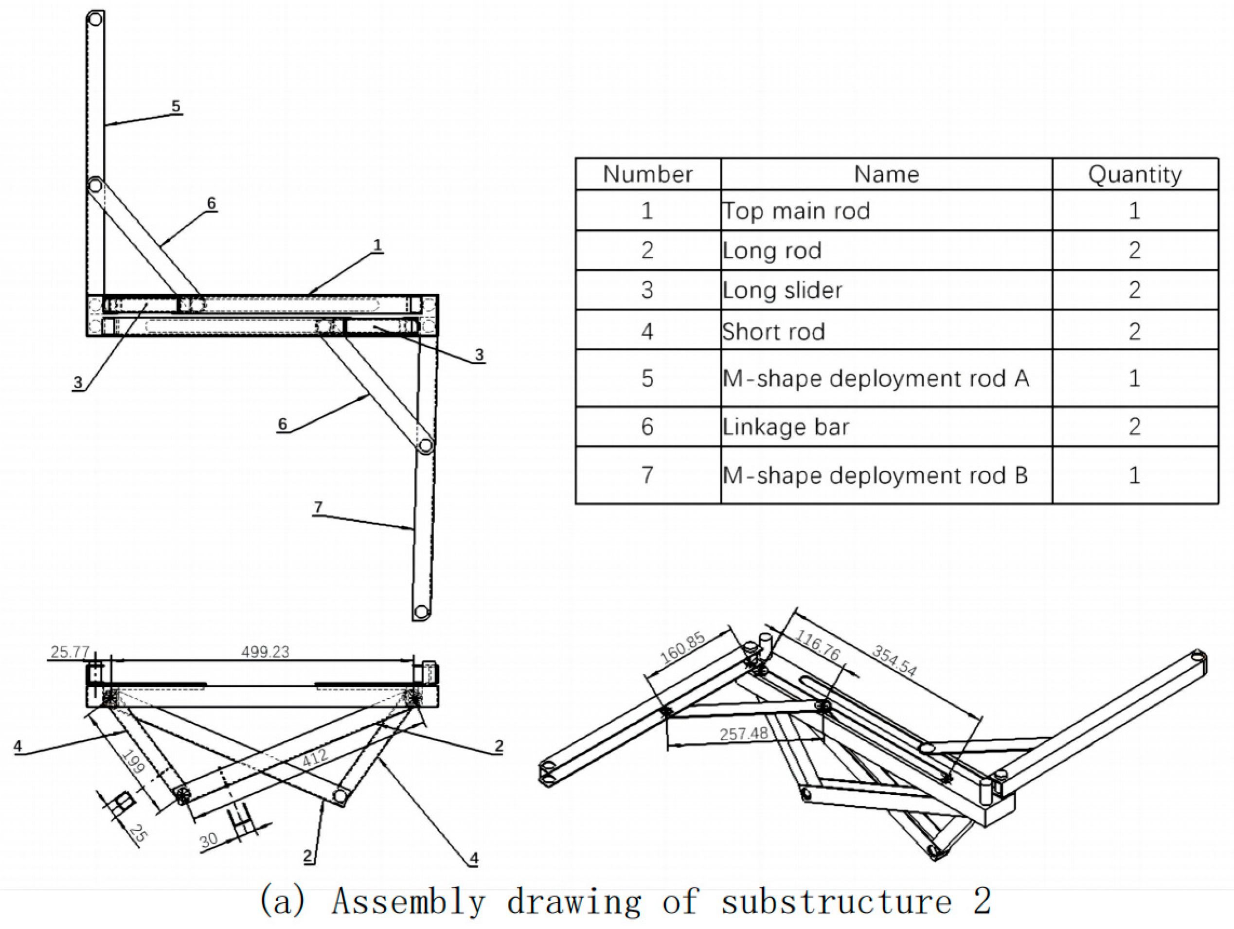
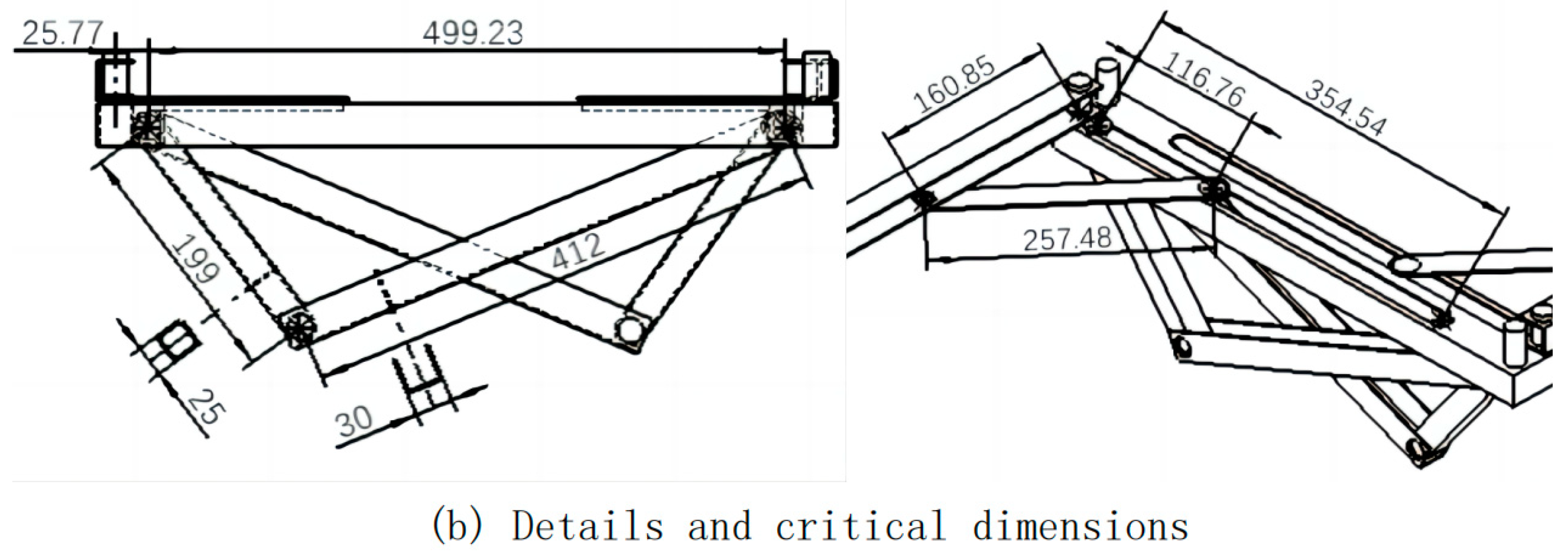
Figure 7.
Design of substructure 1&3.
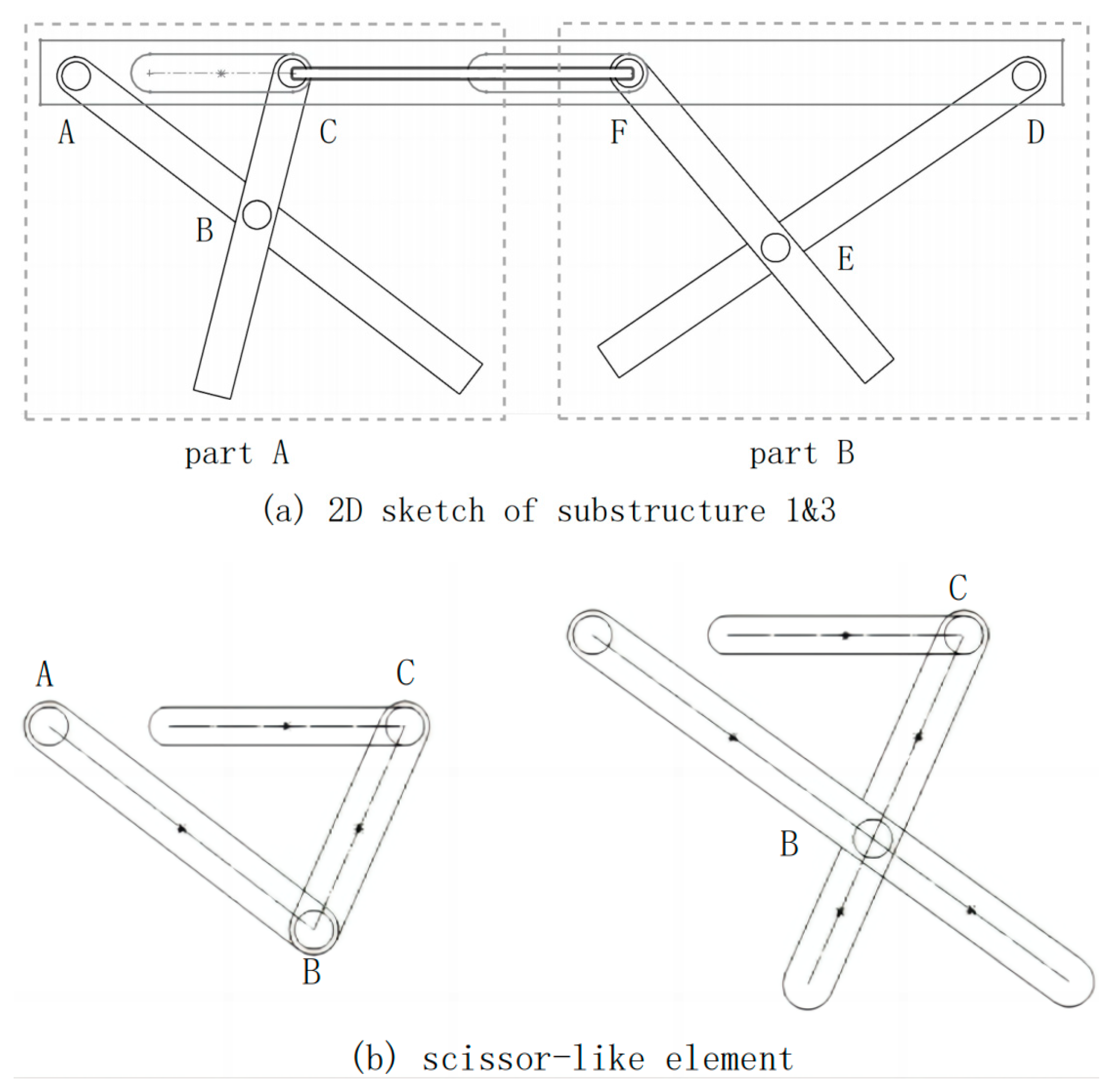
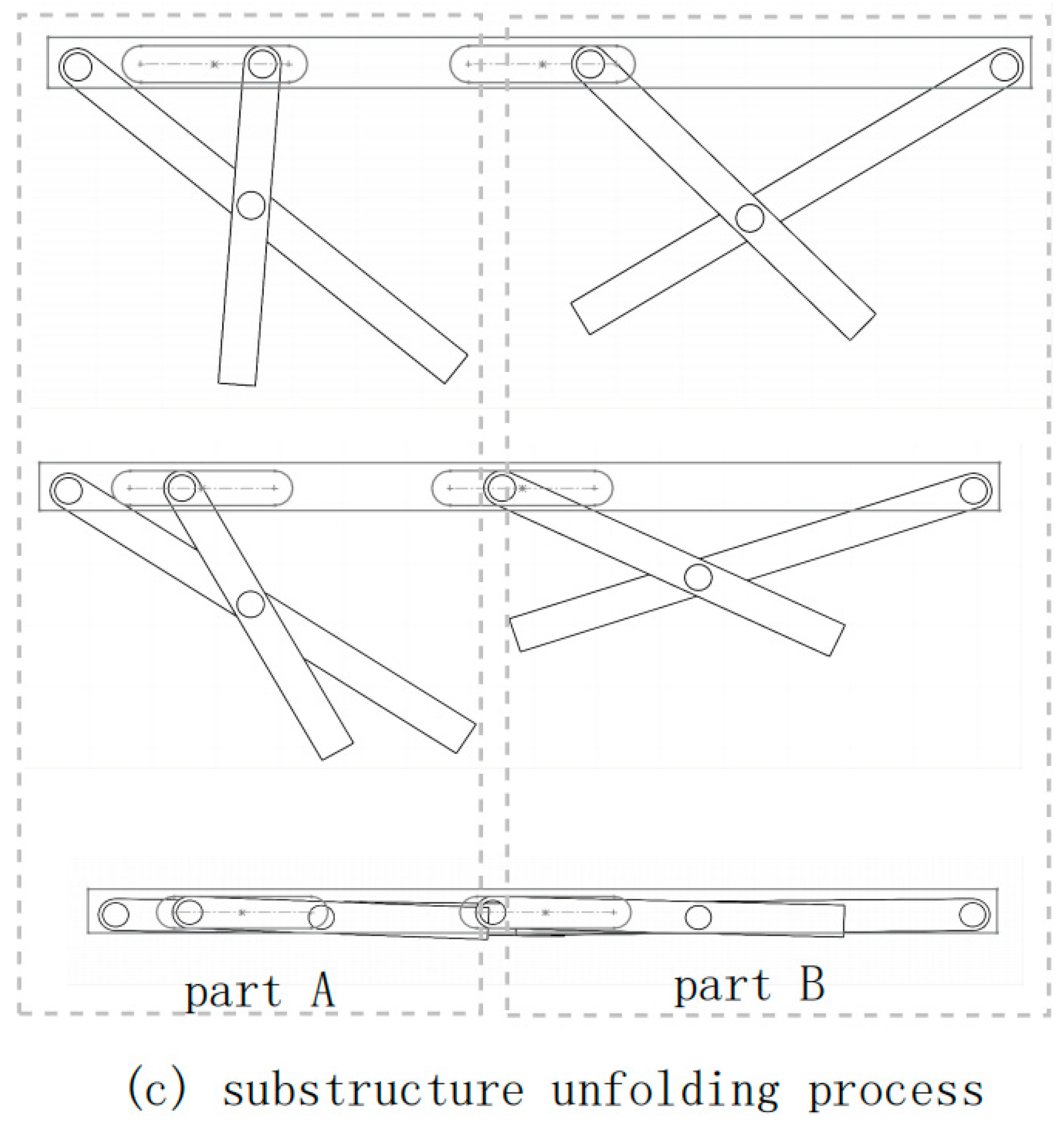
Figure 8.
Assembly drawing of substructure 1&3.
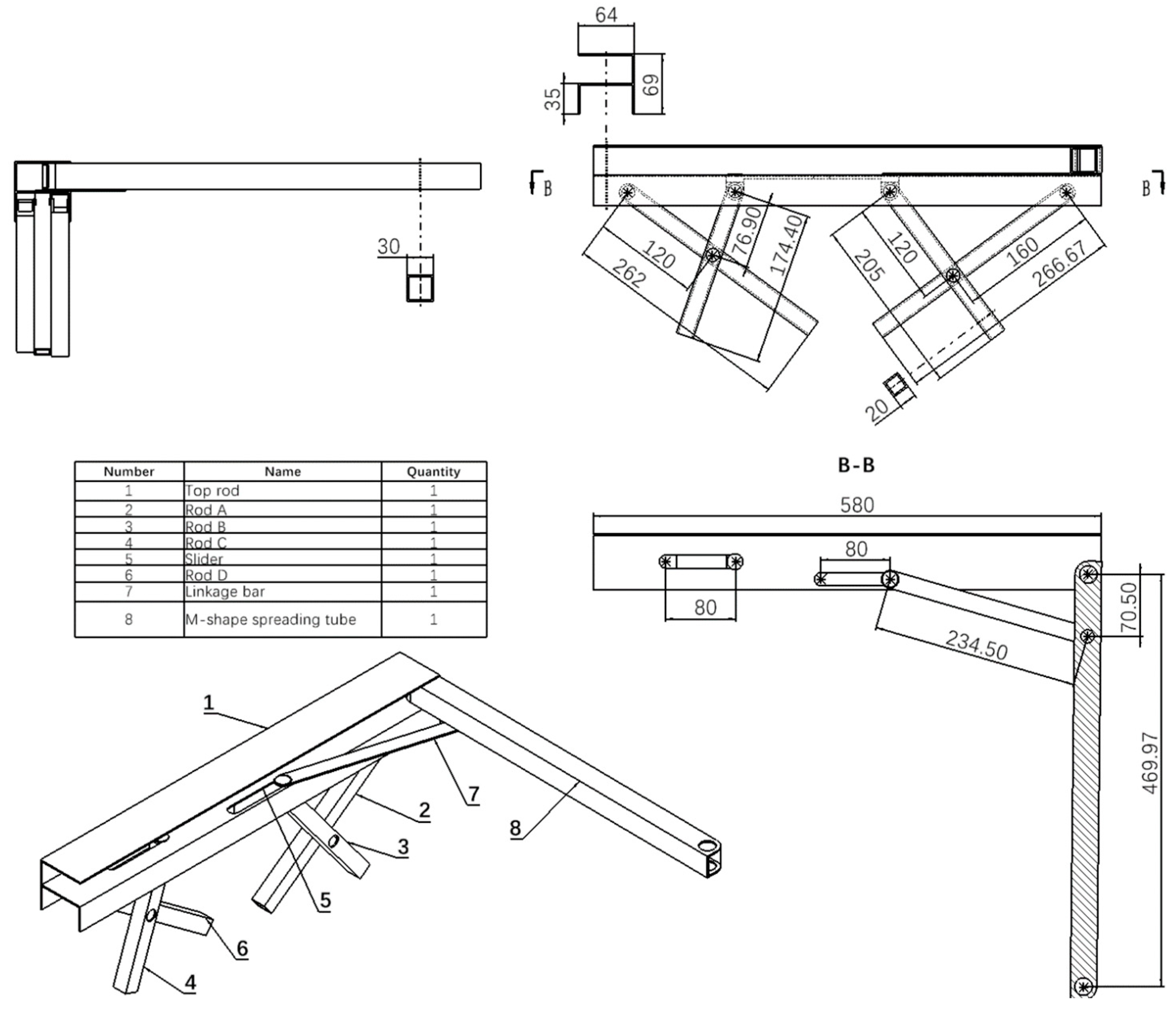
Figure 9.
The first type of rotating joint [11].
Figure 9.
The first type of rotating joint [11].
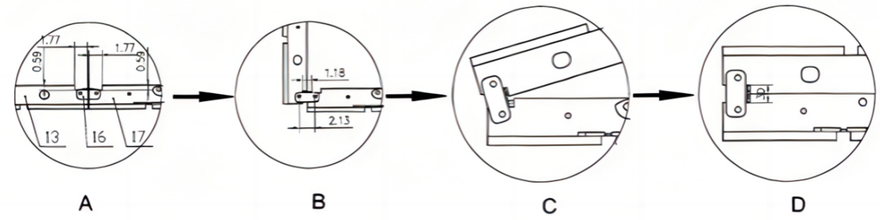
Figure 10.
The second type of rotating joint [12].
Figure 10.
The second type of rotating joint [12].
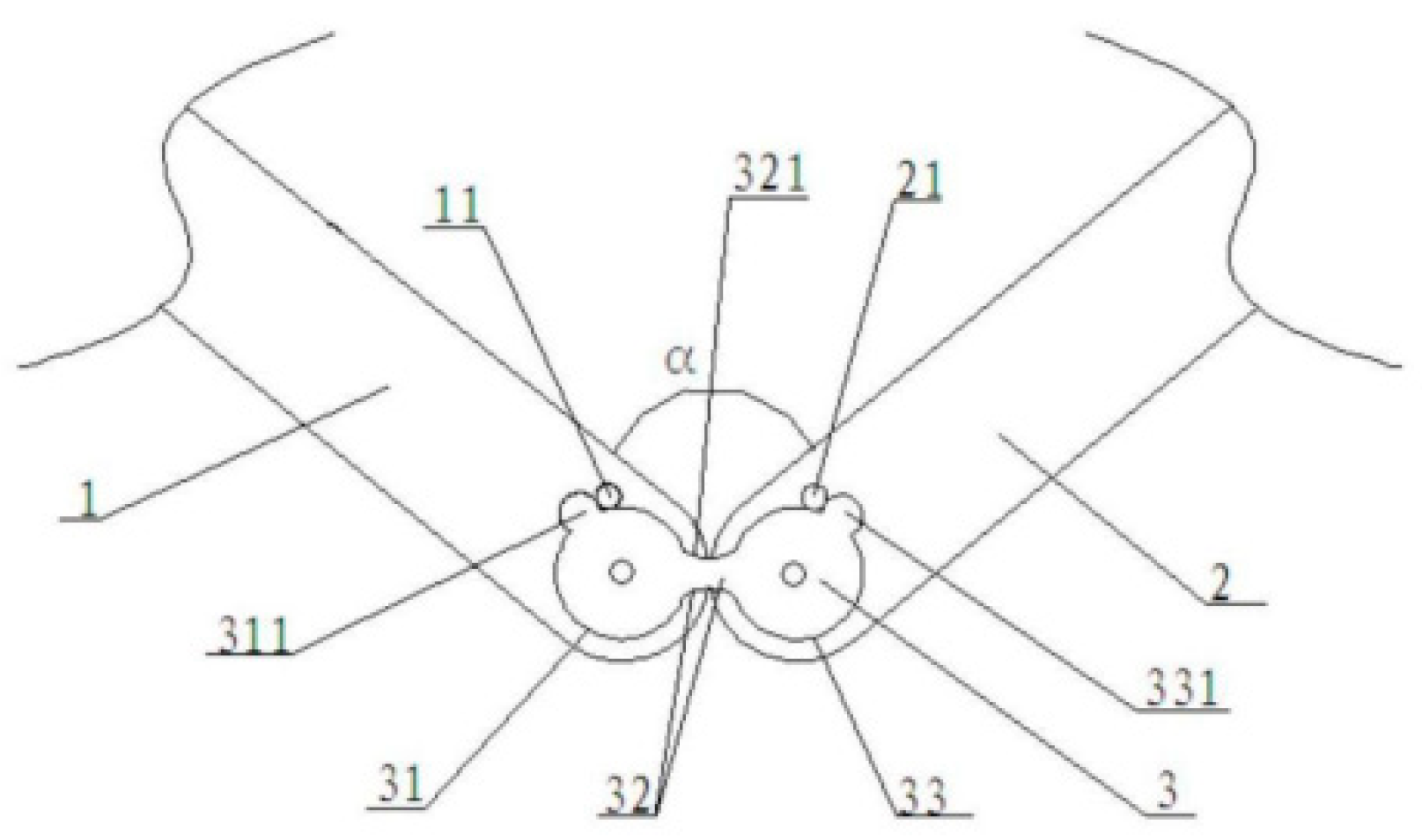
Figure 11.
Diagrams of Substructure 2.
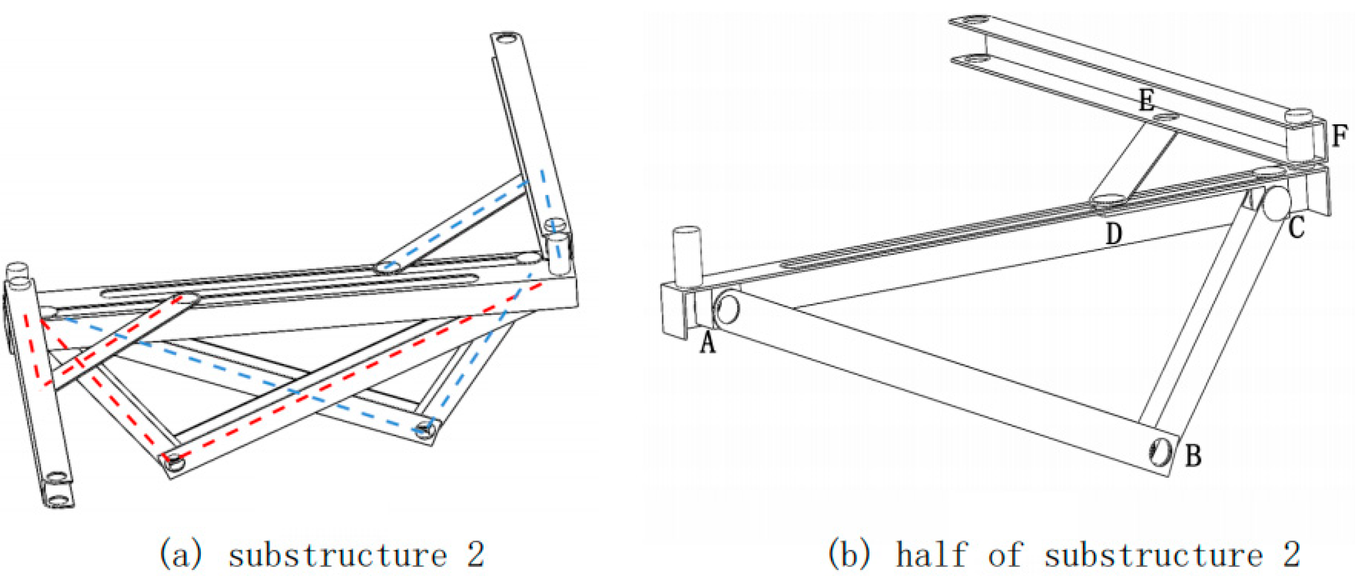
Figure 12.
Simplified diagram of substructures 1&3.
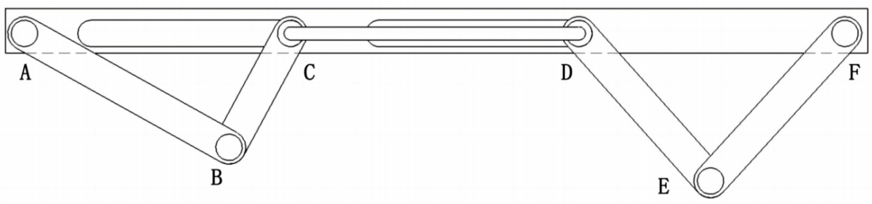
Figure 13.
The simple model of Mechanism 1
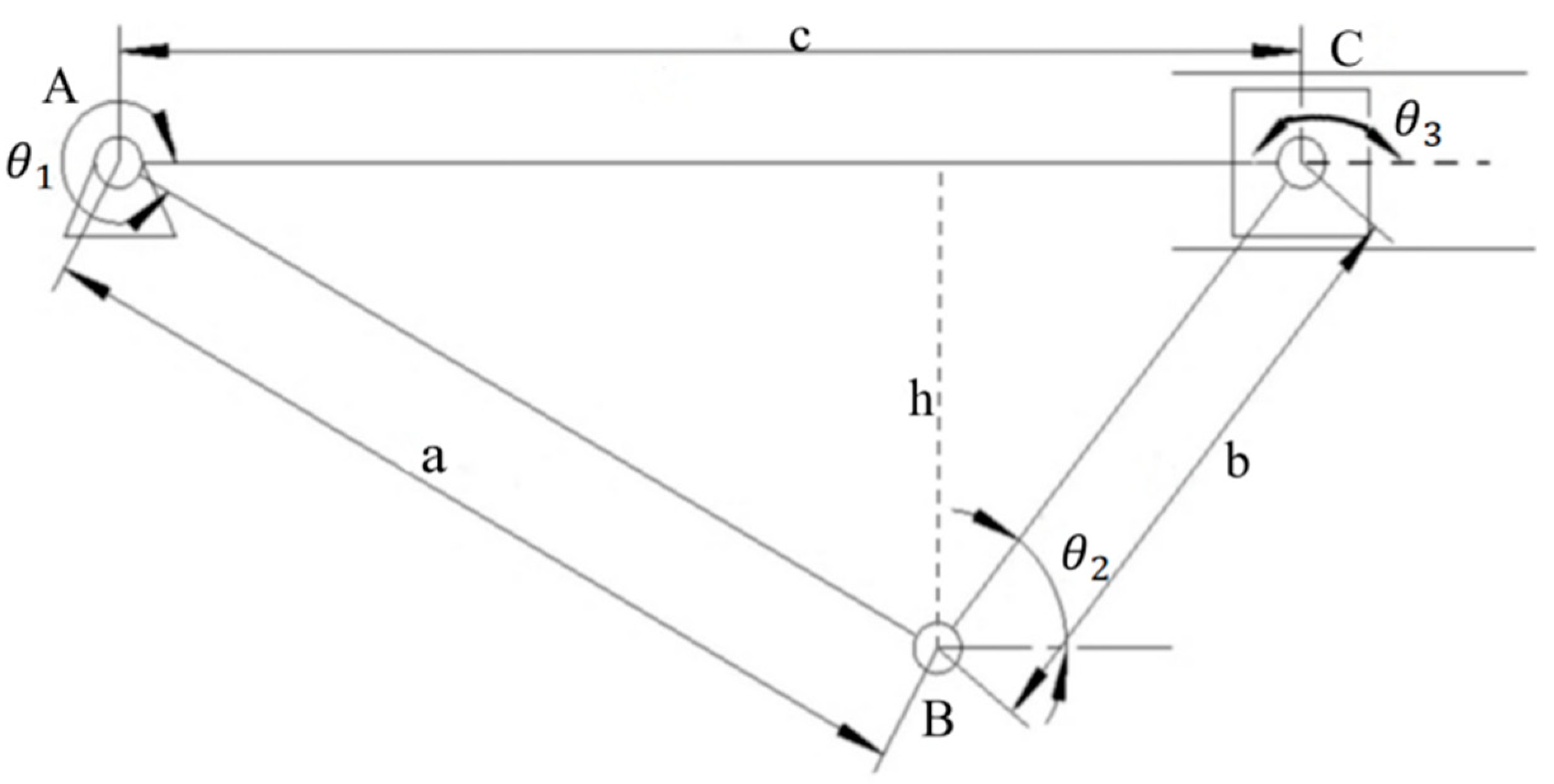
Figure 14.
The bed’s height changes with the decrease of c.
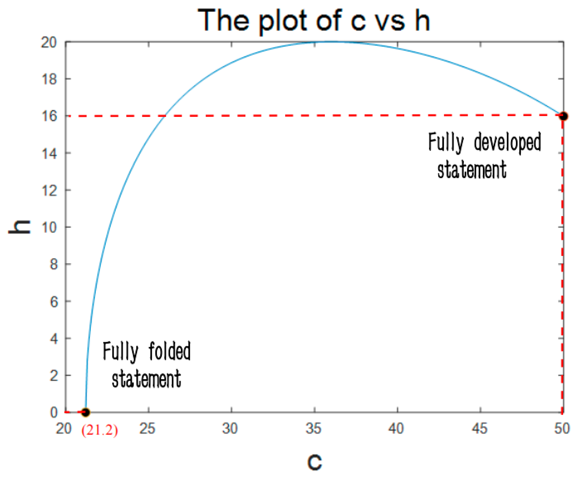
Figure 15.
The simple model of Mechanism 2.
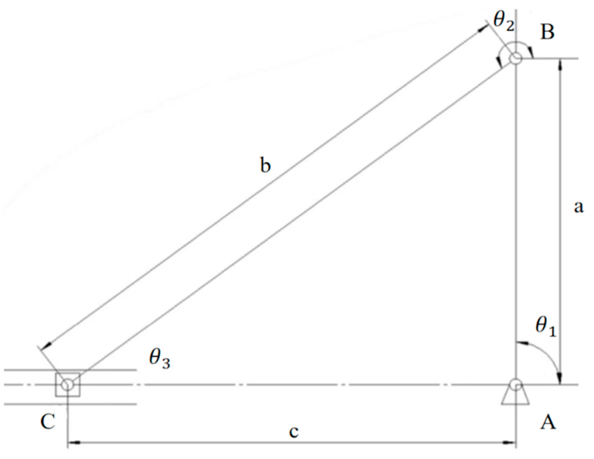
Figure 16.
The angle changes with the increase of c.
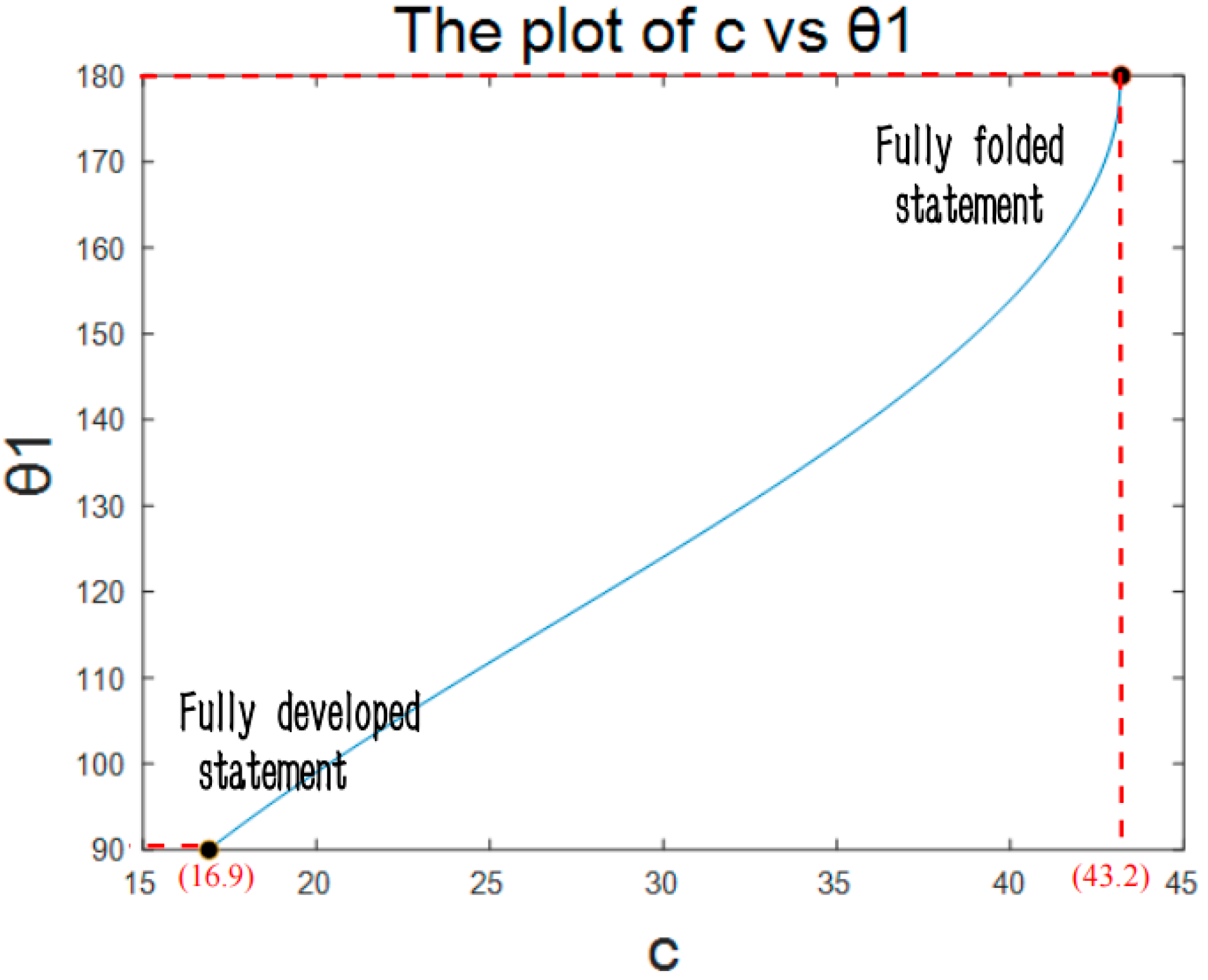
Figure 17.
The simple model of structures 1 and 3.
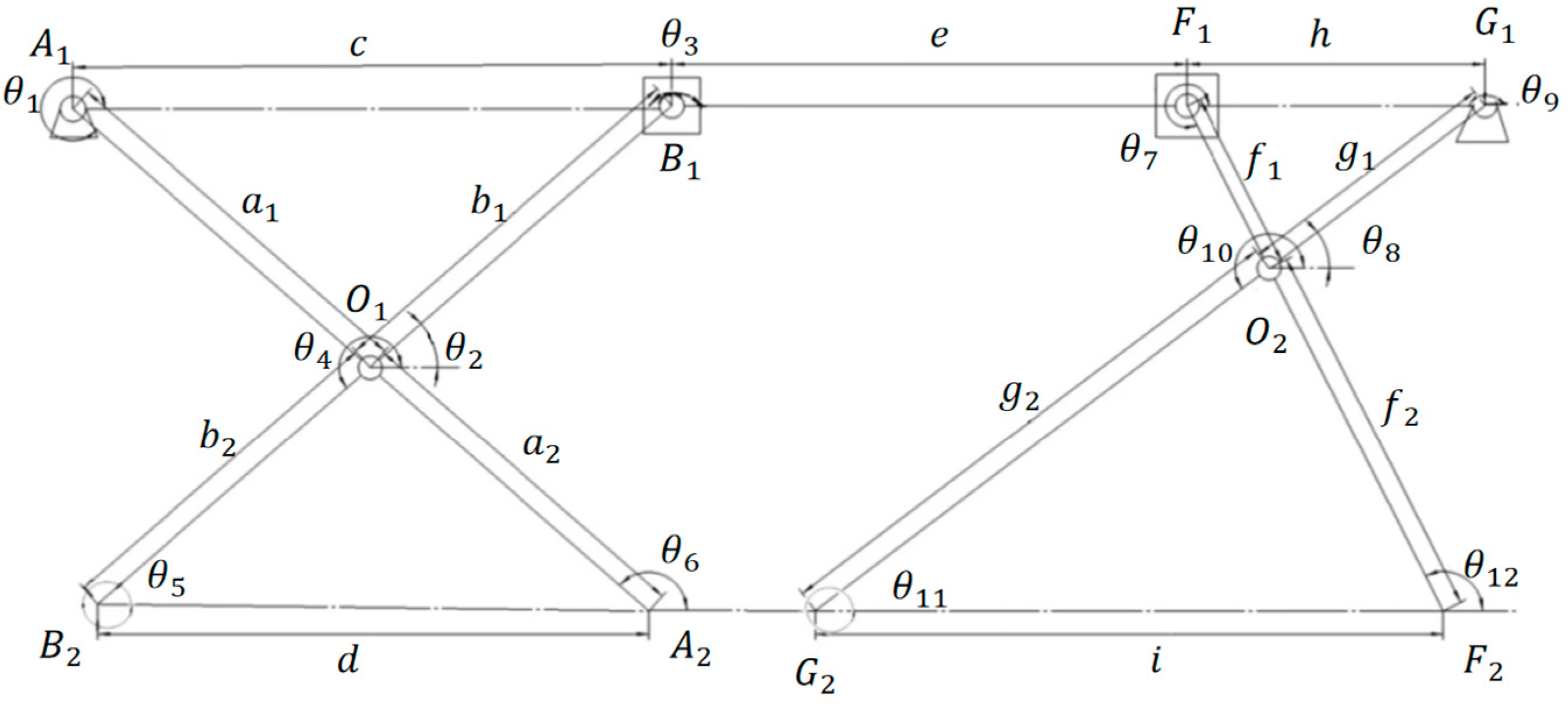
Figure 18.
The angle and change with the increase of c.
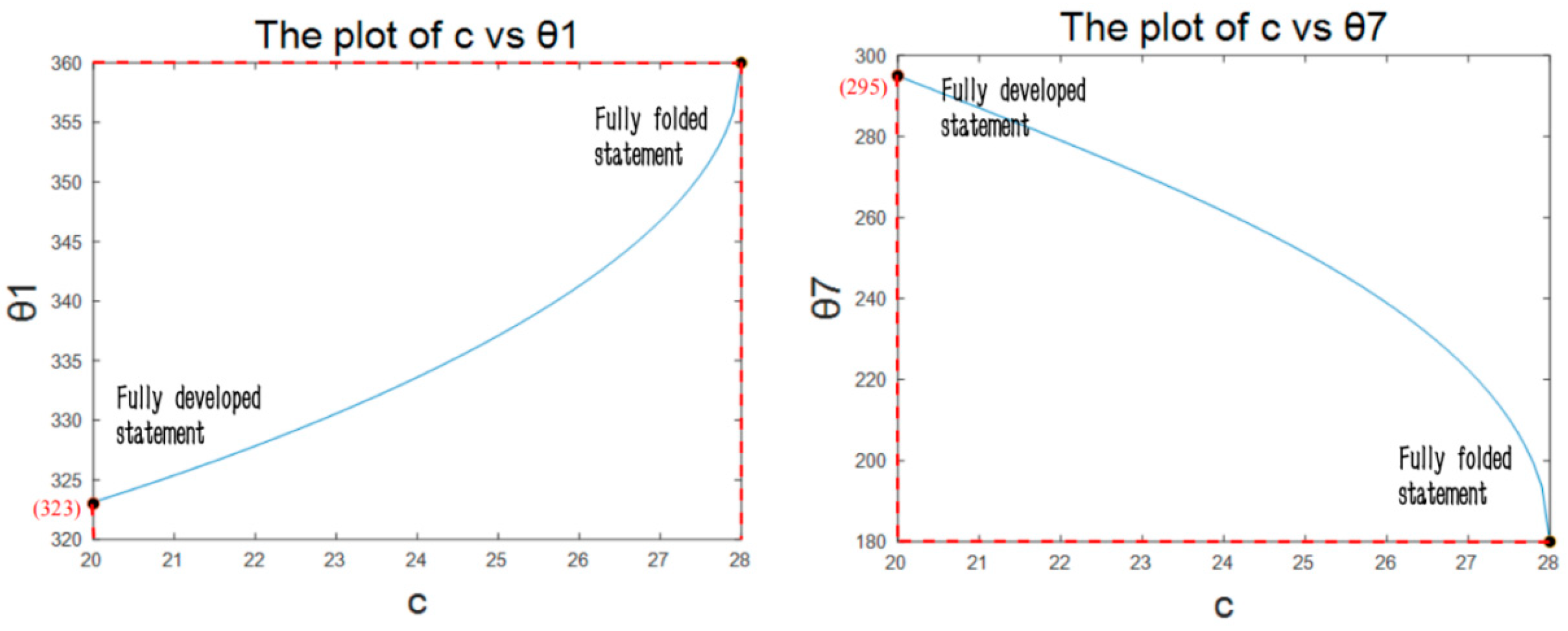
Figure 19.
Folding process of substructure 2.
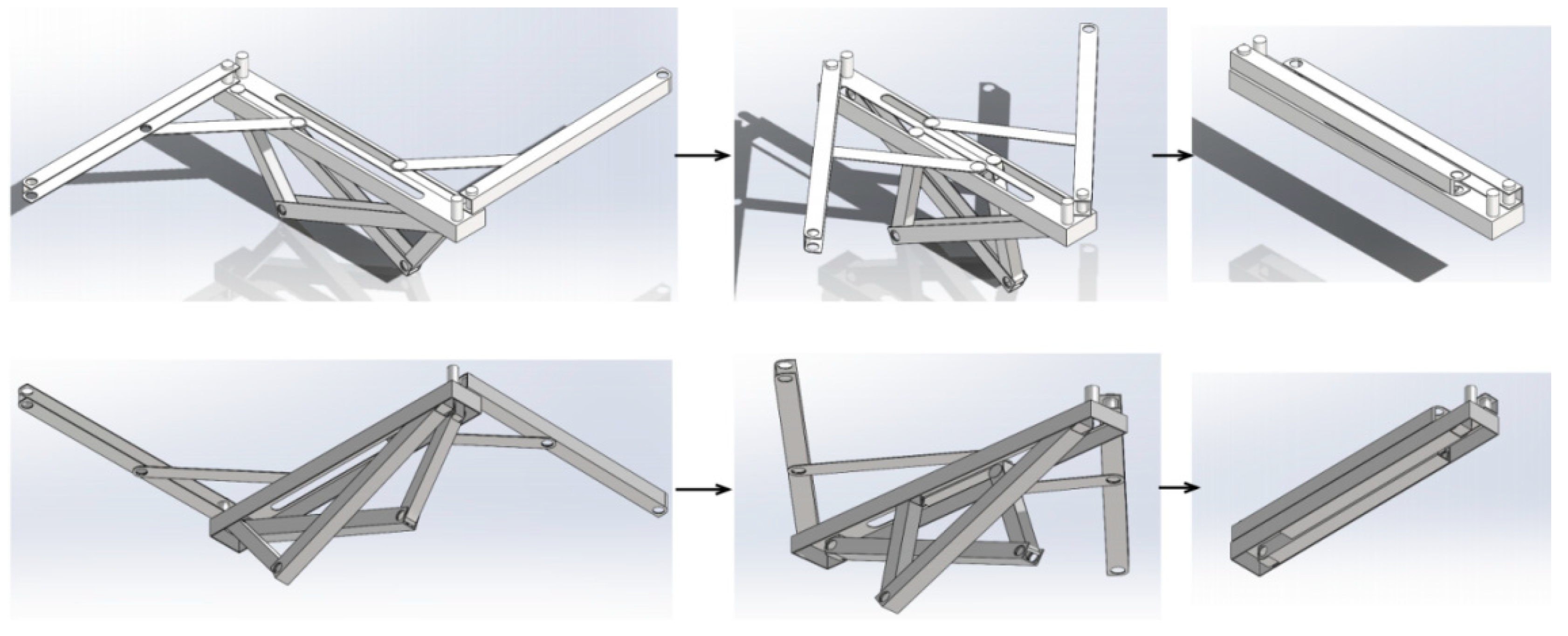
Figure 20.
Folding process of substructure 1&3.
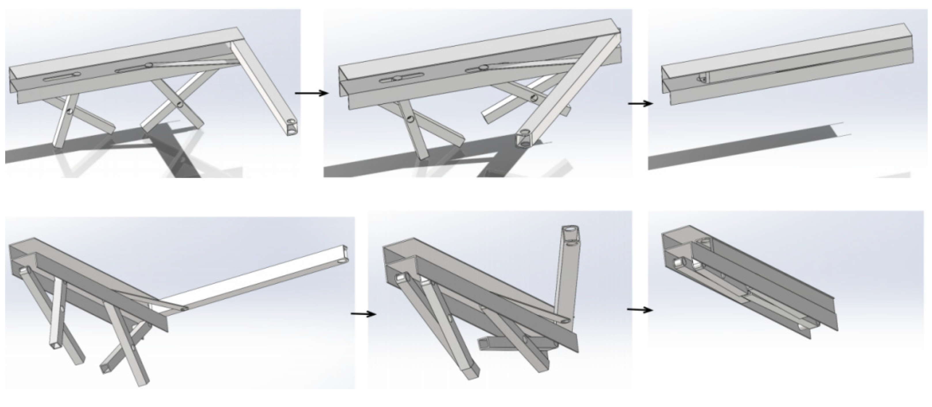
Figure 21.
Folding process of bed (isometric drawing A).
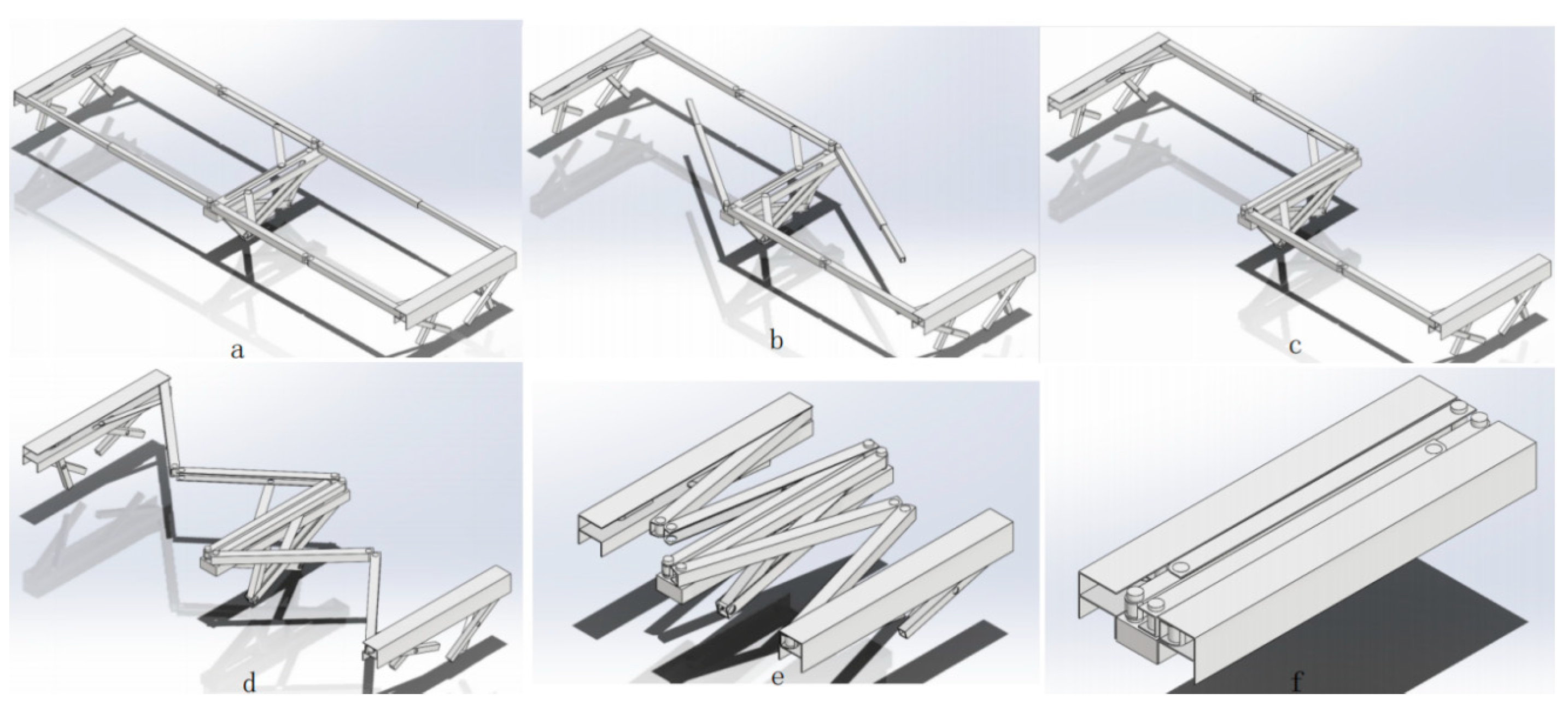
Figure 22.
Folding process of bed (isometric drawing B).
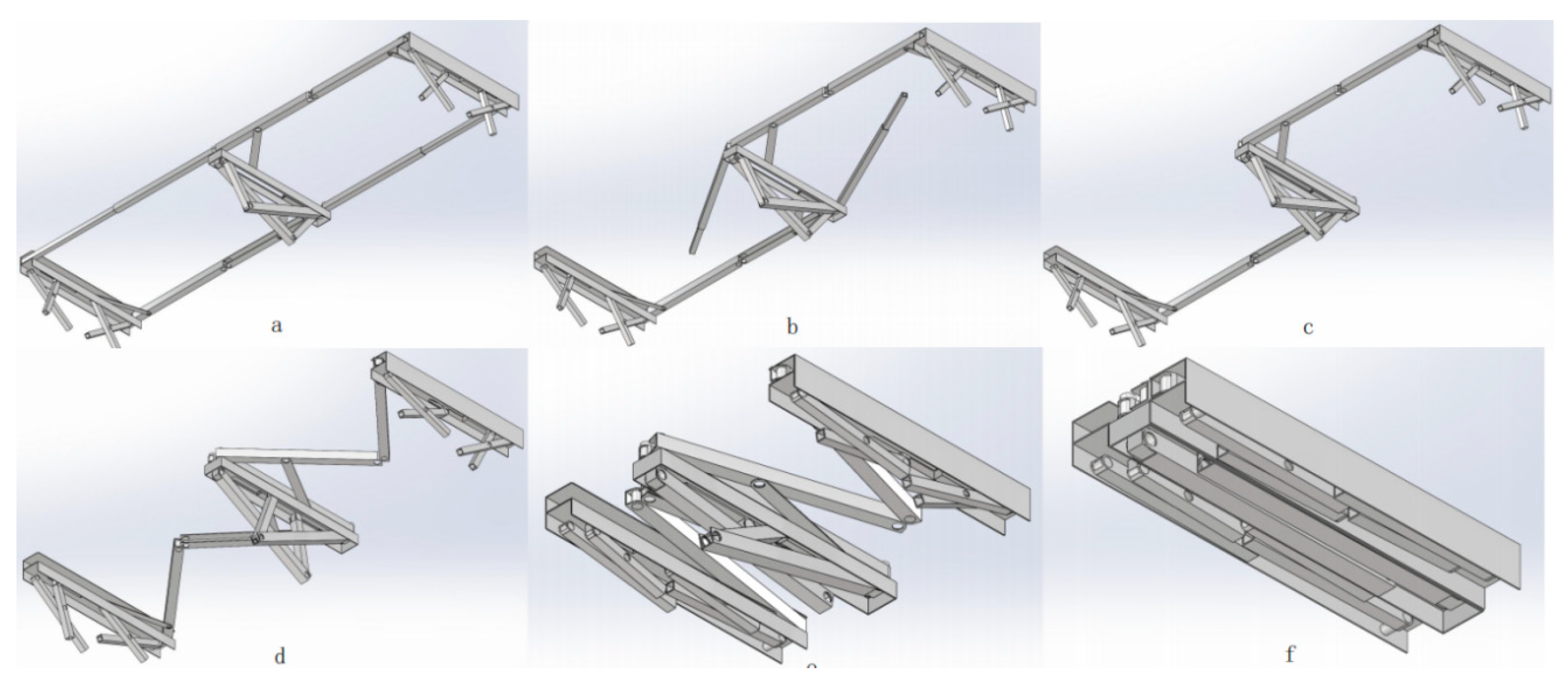
Figure 23.
(a) unfolding. (b) folding.
Disclaimer/Publisher’s Note: The statements, opinions and data contained in all publications are solely those of the individual author(s) and contributor(s) and not of MDPI and/or the editor(s). MDPI and/or the editor(s) disclaim responsibility for any injury to people or property resulting from any ideas, methods, instructions or products referred to in the content. |
© 2024 by the authors. Licensee MDPI, Basel, Switzerland. This article is an open access article distributed under the terms and conditions of the Creative Commons Attribution (CC BY) license (https://creativecommons.org/licenses/by/4.0/).
Copyright: This open access article is published under a Creative Commons CC BY 4.0 license, which permit the free download, distribution, and reuse, provided that the author and preprint are cited in any reuse.


