Submitted:
04 December 2024
Posted:
06 December 2024
You are already at the latest version
Abstract
To address the difficulty in extracting fault features from dual-channel signals, this work proposes a multichannel signal fusion processing method based on Flexible Tensor Singular Spectrum Decomposition (FTSSD) with adaptive embedding dimension selection. Firstly, the optimal embedding dimension of the trajectory tensor is adaptively determined using the proposed Trajectory Dimension Ratio (TDR) index. Once the optimal embedding dimension is obtained, the multichannel signals are represented as an optimal trajectory tensor. Then, FTSSD is employed to decompose the tensor and extract feature component signals. Moreover, by setting a residual threshold or maximum number of components to control the iterative process, the precision and rationality of the decomposition are ensured. Finally, all component signals are reconstructed, and their waveforms and spectra are comprehensively analyzed. Experimental results demonstrate that the proposed adaptive embedding FTSSD algorithm achieves high accuracy and robustness in multichannel signal decomposition and feature extraction, making it suitable for multicomponent analysis of complex dynamic signals such as mechanical fault diagnosis and vibration analysis.
Keywords:
Tensor Decomposition
; Fault Diagnosis
; Information Fusion
; Rolling Bearings
; Signal Processing
1. Introduction
With the continuous development of industrial automation and intelligent production, condition monitoring and fault diagnosis have become essential means to ensure the safe and efficient operation of industrial systems. Efficient decomposition and analysis are crucial for fault diagnosis of mechanical equipment [1,2,3]. In particular, employing two-channel signal acquisition to synchronously capture vibration signals in multiple directions and locations enables a more comprehensive reflection of the equipment’s dynamic characteristics and potential faults. However, due to the complex and variable nature of such signals, existing decomposition algorithms struggle to effectively address this challenge.
In recent years, numerous researchers have sought to improve methods for rolling bearing fault diagnosis. Yin et al. [4] studied a fault diagnosis approach that combines Fast Fourier Transform (FFT) and Convolutional Neural Networks, which significantly improves diagnostic accuracy while reducing dependence on expert experience. However, the feature extraction capabilities are limited, and high-quality training data are required. Wang et al. [5] introduced a bearing fault diagnosis method leveraging deep feature enhancement combined with reinforcement learning to improve diagnostic robustness and capture global information. However, the model is complex, and its interpretability of features is limited. Chen et al. [6] successfully identified weak transient fault features under strong noise environments by combining squared envelope spectrum and successive variational mode decomposition, though the computational cost was high. Fei et al. [7] proposed a hierarchical decision fusion diagnosis method aimed at improving diagnostic accuracy, which can accurately detect faults under different working conditions, locate faults, and estimate fault severity. However, the method has a disadvantage of being complex in model parameter tuning. Xu et al. [8] developed a diagnostic approach that integrates Singular Value Decomposition with the squared envelope spectrum, aiming to address the challenge of weak early defect signals being prone to noise interference and thereby effectively identify early fault types, although its noise suppression capability remains limited. To address compound faults caused by bearings and other components, Fan et al. [9] presented a method based on information fusion, Empirical Mode Decomposition (EMD), and polar coordinate adaptive distribution images for detecting compound faults of rolling bearings and rotors. This method, when dealing with complex compound faults, may require specific handling for each type of fault feature, and its applicability could be limited if confronted with unknown or diverse types of faults. Gao et al. [10] proposed a fault classification method that utilizes Complete Ensemble Empirical Mode Decomposition with Adaptive Noise (CEEMDAN), Fuzzy Measure Entropy (FME), and a Particle Swarm Optimized Probabilistic Neural Network (PSO-PNN) for improved fault detection. This method decomposes noise components from the signal and extracts features using fuzzy measure entropy, followed by classification through an optimized probabilistic neural network, but it has high computational costs. Wu et al. [11] addressed insufficient feature extraction under complex working conditions and low diagnostic accuracy in small datasets by proposing a fault diagnosis method based on MTF-CBAM-IResNet, significantly improving diagnostic accuracy. By introducing Multi-scale Temporal Feature (MTF) and Convolutional Block Attention Module (CBAM), the feature extraction effectiveness is enhanced, and an improved residual network (IResNet) is utilized for more accurate classification. However, the adaptability and generalizability of this method to other fault scenarios or significantly different data distributions still need verification. Jiang et al. [12] proposed a dual-channel CNN rolling bearing fault diagnosis method, which combines Sparrow Search Algorithm optimized Variational Mode Decomposition (SSA-VMD) and Symmetric Dot Pattern (SDP) to address the nonlinearity, nonstationarity, and limited feature extraction performance of single-channel CNN in rolling bearing fault signals. However, the computational complexity remains high, and robustness is limited. To extract and fuse complementary fault features from multi-sensor data, Wang et al. [13] proposed a multi-level feature tensor fusion network for bearing fault diagnosis, effectively improving fault diagnosis performance, though there is a risk of overfitting.
In summary, the above methods still face issues of insufficient resolution, sensitivity to noise, and high computational complexity when handling multi-channel signals. Tensor decomposition, as an effective multidimensional data analysis tool, has increasingly become a research focus in the signal processing field due to its capability to simultaneously handle multi-channel and multidimensional signal data. Particularly, the first-class tensor decomposition method can deeply reveal the intrinsic structure and multidimensional characteristics of signals, providing new insights for the decomposition and feature extraction of complex signals.
However, existing tensor decomposition methods still have shortcomings in practical applications. Firstly, the choice of embedding dimensions significantly affects the signal decomposition effect; fixed embedding dimensions struggle to adapt to the complex dynamic characteristics of different signals, potentially leading to insufficient information capture or excessive noise introduction. Secondly, existing tensor decomposition algorithms face a trade-off between computational efficiency and decomposition accuracy when dealing with large-scale data, necessitating improvements in computational performance while ensuring decomposition effectiveness. To address these issues, this study investigates a novel dual-channel signal decomposition algorithm based on flexible tensor decomposition combined with adaptive dimension selection. By introducing a Tensor Dynamic Range (TDR) metric, the embedding dimensions are adaptively selected to ensure that the embedding dimensions automatically adjust with changes in signal characteristics, thereby improving the accuracy of signal decomposition. Furthermore, this study aims to enhance the efficiency and precision of multi-channel signal decomposition through improved tensor decomposition methods. The main contributions of this work are as follows:
(1) A trajectory tensor embedding dimension adaptive selection algorithm is proposed, allowing dynamic adjustment of embedding dimensions based on signal component characteristics.
(2) A high-efficiency and accurate dual-channel signal decomposition is realized through flexible tensor decomposition, enhancing the overall performance of signal analysis.
The remainder of this paper is organized as follows: Section 1 introduces the adaptive embedding dimension selection method and its implementation steps; Section 2 elaborates on the flexible tensor decomposition principle and the new algorithm; Section 3 presents the experimental design and result analysis for the proposed algorithm in dual-channel signals, verifying the effectiveness of the proposed method; Section 4 provides the conclusions.
Through this research, we aim to provide an efficient, robust, and adaptive approach for dual-channel signal decomposition and analysis, advancing the application and development of advanced signal processing techniques in areas such as mechanical fault diagnosis.
2. Adaptive Embedding Dimension Method
The embedding dimension refers to the number of dimensions used when mapping the original multidimensional signal to a higher-dimensional space in signal processing and tensor decomposition. Specifically, the embedding dimension determines the representation of data in the high-dimensional space, directly impacting the effectiveness of signal feature capture and the accuracy of subsequent analysis. In the tensorization of multi-channel signals, the embedding dimension is used to construct high-order tensors to fully reflect the complex dynamic characteristics of the signal. The selection of the embedding dimension plays a crucial role in time-series analysis and signal processing. Traditional methods typically use a fixed embedding dimension, which may lead to insufficient feature capture or overfitting. To address the limitations of embedding dimension in tensor decomposition, Feng et al. [14] proposed a rolling bearing fault diagnosis method based on a multi-level denoising approach and an improved deep residual network, optimizing matrix singular value decomposition. This method automatically determines the optimal embedding dimension by calculating the DR value under different embedding dimensions. Building on this foundation, this paper proposes the TDR index:
where represent the elements of the first to third horizontal slices of the core tensor in the tensor singular value decomposition, and is the weighting coefficient, with a range of . Each trajectory tensor dimension corresponds to a TDR value, and the dimension with the highest TDR index is considered the optimal embedding dimension. Figure 1 illustrates the calculation and application process of the TDR index.
3. Flexible Tensor Singular Spectrum Decomposition
Tensor Decomposition is an essential tool in multidimensional data analysis, used to decompose high-order tensors (multi-dimensional arrays) into combinations of simpler, structured lower-order tensors. Tensor decomposition has broad applications in various fields, including signal processing, machine learning, image analysis, and natural language processing, and demonstrates significant advantages, especially when handling multi-channel and multi-dimensional signals.
Traditional tensor decomposition, such as CP decomposition and Tucker decomposition based on n-mode products, suffer from inherent issues like non-unique rank and non-pseudo-diagonal core tensor. Additionally, T-T product [[13] can only be used for multiplication between tensors of the same order, greatly limiting the applicability of tensor singular value decomposition algorithms based on T-T product. Flexible tensor product is one of the latest advancements in tensor decomposition theory [16], and can be represented as:
where p and q represent the respective orders for the first and second tensors. Here, the symbol ‘1’ denotes the forward order, i.e., the sequence of tensor modes follows the forward index, while ‘2’ indicates the reverse order, following the reverse index. The parameter o, a positive integer, indicates the order for the multiplier during tensor product, with an allowable range of . This flexibility provides more computational possibilities for tensor multiplication, making it adaptable to various application scenarios. To clearly denote the different forms of flexible tensor products, Ref. [16] described it as “o-order (p, q)-mode product.” This terminology provides a straightforward way to identify the particular type of tensor multiplication. Based on the flexible tensor product, the first kind of flexible tensor singular value decomposition can be derived:
where and are orthogonal singular tensors, and is the core tensor. The first kind of flexible tensor singular value decomposition (1K-FTSVD) for a third-order tensor is illustrated in Figure 2.
As observed in Figure 2, it is evident that the 1K-FTSVD method breaks down third-order tensors into three constituent tensors: , and . The left singular tensor and the right singular tensor are both of second order. Furthermore, 1K-FTSVD guarantees a unique decomposition result and maintains a simple computation process. Based on the principle of 1K-FTSVD, an adaptive embedding Flexible Tensor Singular Spectrum Decomposition (FTSSD) algorithm is constructed.
For multichannel signals, tensorization is performed to map the time series of k channels with N sampling points into a third-order tensor space, in order to capture the high-dimensional characteristics of the signal. Each forward slice of third-order tensors corresponds to a trajectory matrix for:
where , , and is the embedding dimension.
The selection of the embedding dimension is adaptively determined using the TDR formula. Subsequently, the resulting trajectory tensor undergoes tensor singular value decomposition, which is expressed as:
This process achieves dimensionality reduction and feature extraction by progressively extracting the characteristic components from multichannel signals. In the reconstruction process, all feature components are first divided into two disjoint sets , where the tensor for group is calculated using the following formula:
where . This method of tensor selection avoids including noise signals with large singular values. Subsequently, tensor undergoes diagonal averaging, and the next iteration is carried out using the residual signal. This iterative process concludes when the normalized mean squared error drops below a specified threshold. The proposed adaptive embedding FTSSD algorithm can effectively decompose and reconstruct multichannel signals, extracting physically meaningful signal components while removing interfering noise.
4. Result Analysis
4.1. Simulation Signal Analysis
To verify the effectiveness of the proposed method, we first introduced random noise into the simulation signals and processed the faulty signals of the bearing. Figure 3 presents the dual-channel time-domain, frequency spectrum, and envelope spectrum of the bearing simulation signal after adding noise. It can be observed that under the interference of noise, the bearing fault features are difficult to effectively identify and extract.
Next, we applied the proposed adaptive embedding FTSSD to process the simulation signals. Figure 4 shows the processed signal. It is evident that the bearing fault features, formerly masked by noise, are clearly extracted. This demonstrates that the proposed method could effectively extract the bearing fault features from noisy signals. These processed results indicate that the proposed method possesses strong anti-interference capability, enabling accurate capture of critical fault information even in high-noise environments.
4.2. Experimental Signal Analysis
To further verify the effectiveness of the proposed method under actual working conditions, the signals from the bearing test rig were analyzed. The experimental setup is shown in Figure 5, where the AC motor speed was set to 2250 r/min, the sampling frequency was Fs=25600 Hz, and the bearing outer race fault characteristic frequency was fo=115.61Hz. Random noise was added during the experiment to simulate realistic complex conditions. Figure 6 shows the time-domain waveforms and frequency spectra of the two-channel signals, where the fault characteristic frequency of the bearing outer race is difficult to identify in the envelope spectrum, and numerous interference components are present in the frequency spectrum.
Subsequently, the proposed method was applied to the experimental signals. Figure 7 presents the time-domain, frequency spectrum, and envelope spectrum of the dual-channel component signals. It can be clearly observed from Figure 7 that the fault characteristic frequency of the bearing outer race and its harmonics were effectively extracted. This demonstrates that the proposed method significantly enhances the feature extraction performance for multichannel signals.
To further validate the superiority of the proposed method, Tensor Robust Principal Component Analysis [17] was employed for comparative analysis of the experimental signals. Figure 8 shows the time-domain, frequency spectrum, and envelope spectrum of the dual-channel components processed by TRPCA. Compared to Figure 7, the signal-to-noise ratio in Figure 8 is significantly lower, and the extraction of the outer race characteristic frequency and its harmonics (1st to 3rd) in the envelope spectrum is less effective than with the proposed method.
Based on the above experimental results, it can be concluded that the proposed adaptive embedding FTSSD signal decomposition method demonstrates superior fault feature extraction capability in noisy environments, with both diagnostic accuracy and signal-to-noise ratio outperforming the traditional Tensor Robust Principal Component Analysis (TRPCA) method. This indicates that the proposed method has high practicality and effectiveness in multichannel signal decomposition, particularly for fault diagnosis tasks in complex dynamic environments.
5. Conclusions
This work proposed a multichannel signal fusion processing algorithm based on adaptive embedding FTSVD for the decomposition and analysis of dual-channel signals. The proposed TDR index was utilized to achieve adaptive selection of the embedding dimension, effectively improving the accuracy of signal decomposition. By constructing trajectory tensors and performing flexible tensor singular value decomposition, the optimal embedding dimension was adaptively determined, making the signal decomposition more precise and efficient. Experimental results demonstrated that the proposed method has significant advantages in the decomposition of dual-channel signals, effectively extracting the main features of the signal even in noisy environments. Compared to existing methods, the proposed approach better extracted the fault characteristic frequency and its harmonics, exhibited higher signal-to-noise ratio and diagnostic accuracy.
Author Contributions
Huaicheng Ma: Conceptualization, Methodology, Software, Writing - original draft. Jingran Li: Conceptualization, Methodology, Software, Investigation, Formal analysis, Writing - original draft. Jinfeng Huang: Writing - review and editing. Ruijian Wang: Writing - review & editing. Rui Ge: Writing - review and editing. Feibin Zhang: Resources, Supervision, Validation, Writing - review and editing, Conceptualization. All authors have read and agreed to the published version of the manuscript.
Funding
This work is supported by the National Natural Science Foundation of China under Grant No. 52105109, the National Natural Science Foundation of China under Grant No. 52305115, and the China Postdoctoral Science Foundation No. 2023M741938.
Data Availability Statement
The data used in this study are publicly available from a dataset referenced in DOI: 10.1109/TR.2018.2882682. For more details, please refer to the publicly archived dataset analyzed during this study.
Acknowledgments
The authors are grateful to the editors and anonymous reviewers for their helpful comments and constructive suggestions.
Conflicts of Interest
The authors declare that they have no known competing financial interests or personal relationships that could have appeared to influence the work reported in this paper.
References
- Islam M. M., M. , Kim J. M. Automated bearing fault diagnosis scheme using 2D representation of wavelet packet transform and deep convolutional neural network. Computers in Industry, 2019, 106, 142–153. [Google Scholar]
- Xu, H.; Wang, X.; Huang, J.; Zhang, F.; Chu, F. Semi-supervised multi-sensor information fusion tailored graph embedded low-rank tensor learning machine under extremely low labeled rate. Inf. Fusion 2023, 105. [Google Scholar] [CrossRef]
- Huang, J.; Zhang, F.; Safaei, B.; Qin, Z.; Chu, F. The flexible tensor singular value decomposition and its applications in multisensor signal fusion processing. Mech. Syst. Signal Process. 2024, 220. [Google Scholar] [CrossRef]
- Yin, W.; Xia, H.; Peng, B. , et al. A fault diagnosis method of rolling bearing based on FFT and CNN. Appl. Sci. Technol. 2021, 48, 97–101. [Google Scholar]
- Wang, R.; Jiang, H.; Zhu, K.; Wang, Y.; Liu, C. A deep feature enhanced reinforcement learning method for rolling bearing fault diagnosis. Adv. Eng. Informatics 2022, 54. [Google Scholar] [CrossRef]
- Chen, Z.; Jiang, Y.; Wang, Y. , et al. Fault Diagnosis of Rolling Bearings Based on SVMD-SES. Noise Vib. Control 2024, 44, 107–113. [Google Scholar]
- Fei, J.; Lv, X.; Cao, Y.; Li, S. A Hierarchical Decision Fusion Diagnosis Method for Rolling Bearings. Appl. Sci. 2021, 11, 739. [Google Scholar] [CrossRef]
- Xu, L.; Chatterton, S.; Pennacchi, P. Rolling element bearing diagnosis based on singular value decomposition and composite squared envelope spectrum. Mech. Syst. Signal Process. 2021, 148. [Google Scholar] [CrossRef]
- Hongwei, F.; Ceyi, X.; Jiateng, M.; Xiangang, C.; Xuhui, Z. A novel intelligent diagnosis method of rolling bearing and rotor composite faults based on vibration signal-to-image mapping and CNN-SVM. Meas. Sci. Technol. 2022, 34, 044008. [Google Scholar] [CrossRef]
- Gao, S.; Chen, X.; Zhang, Y. , et al. Fault Diagnosis of Rolling Bearing Based on CEEMDAN and Entropy Features. Mech. Des. Manuf. 2024, 1–5. [Google Scholar] [CrossRef]
- Wu, L.; Dong, L. Fault diagnosis method for rolling bearings based on MTF-CBAM-IResNet. Manuf. Technol. Mach. Tools 2024, 1-10. http://kns.cnki.net/kcms/detail/11.3398.th.20240717.1456.034.html.
- Jiang, L.; Gao, M.; Li, H. Fault identification method for bearings based on dual channel CNN using SSA-VMD and SDP. Electromech. Eng. 2024, 1-11. http://kns.cnki.net/kcms/detail/33.1088.th.20240910.1730.008.html.
- Wang, D.; Li, Y.; Song, Y.; Zhuang, Y. Bearing Fault Diagnosis Method based on Multiple-level Feature Tensor Fusion. IEEE Sensors J. 2024, PP, 1–1. [Google Scholar] [CrossRef]
- Feng, Z.; Wang, S.; Yu, M. A fault diagnosis for rolling bearing based on multilevel denoising method and improved deep residual network. Digit. Signal Process. 2023, 140. [Google Scholar] [CrossRef]
- Kilmer M., E. , Martin C. D., and Perrone L. A third-order generalization of the matrix SVD as a product of third-order tensors. Tufts University, Department of Computer Science, Tech. Rep., 2008.
- Huang, J.; Zhang, F.; Coombs, T.; Chu, F. The first-kind flexible tensor SVD: innovations in multi-sensor data fusion processing. Nonlinear Dyn. 2024, 1–19. [Google Scholar] [CrossRef]
- Lu, C.; Feng, J.; Chen, Y.; Liu, W.; Lin, Z.; Yan, S. Tensor Robust Principal Component Analysis: Exact Recovery of Corrupted Low-Rank Tensors via Convex Optimization. In Proceedings of the IEEE Conference on Computer Vision and Pattern Recognition, Las Vegas, NV, USA, 27–30 June 2016; pp. 5249–5257. [Google Scholar] [CrossRef]
Figure 1.
TDR index calculation process.
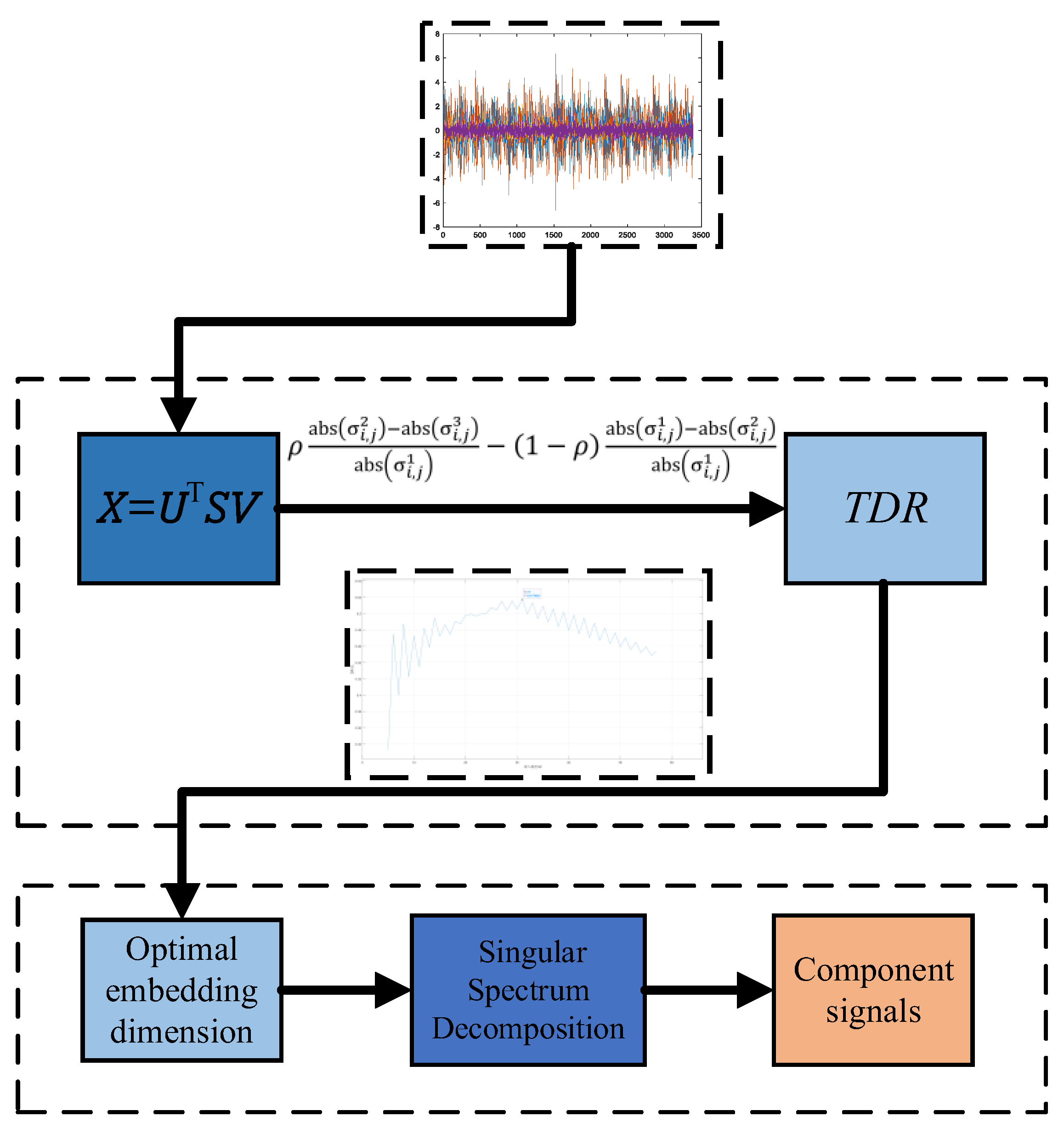
Figure 2.
The first kind of singular value decomposition of third-order tensors.
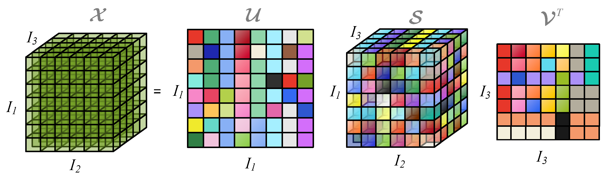
Figure 3.
Simulation signal with added noise: (a) First channel signal waveform; (b) First channel frequency spectrum; (c) First channel envelope spectrum; (d) Second channel signal waveform; (e) Second channel frequency spectrum; (f) Second channel envelope spectrum.
Figure 3.
Simulation signal with added noise: (a) First channel signal waveform; (b) First channel frequency spectrum; (c) First channel envelope spectrum; (d) Second channel signal waveform; (e) Second channel frequency spectrum; (f) Second channel envelope spectrum.
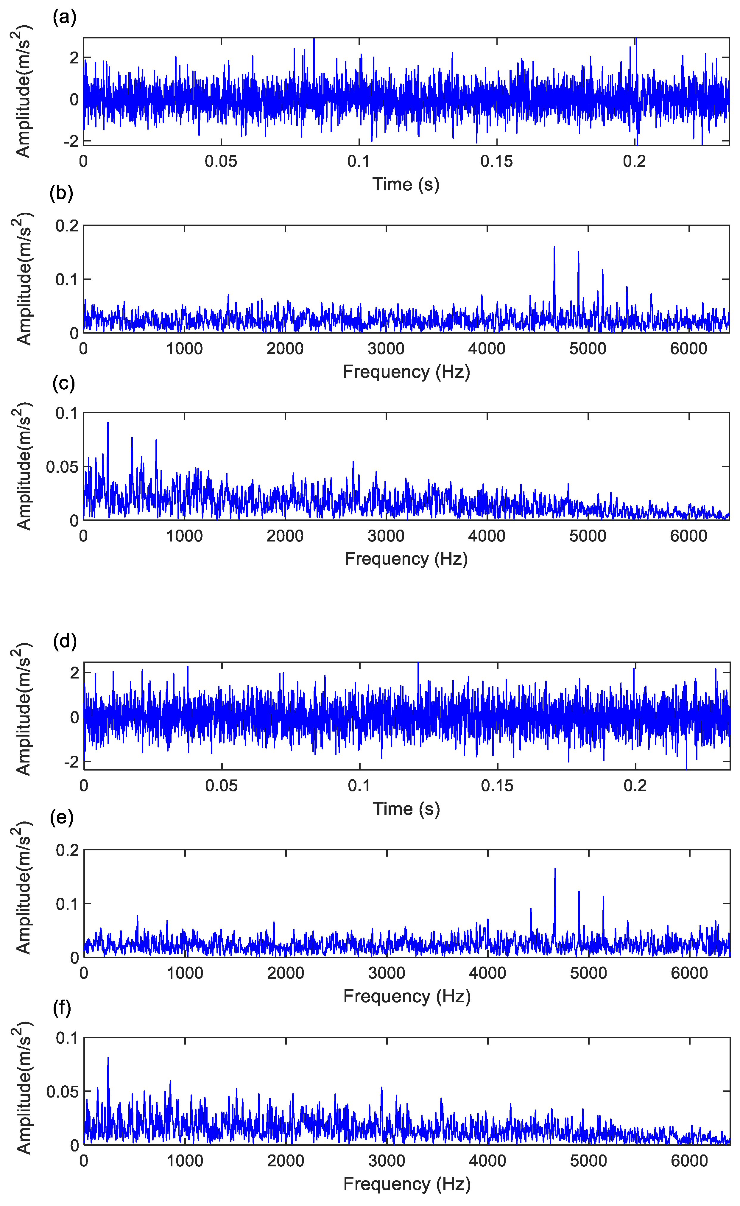
Figure 4.
The first component of the experimental signal using the proposed method: (a) First channel time-domain waveform; (b) First channel frequency spectrum; (c) First channel envelope spectrum; (d) Second channel time-domain waveform; (e) Second channel frequency spectrum; (f) Second channel envelope spectrum.
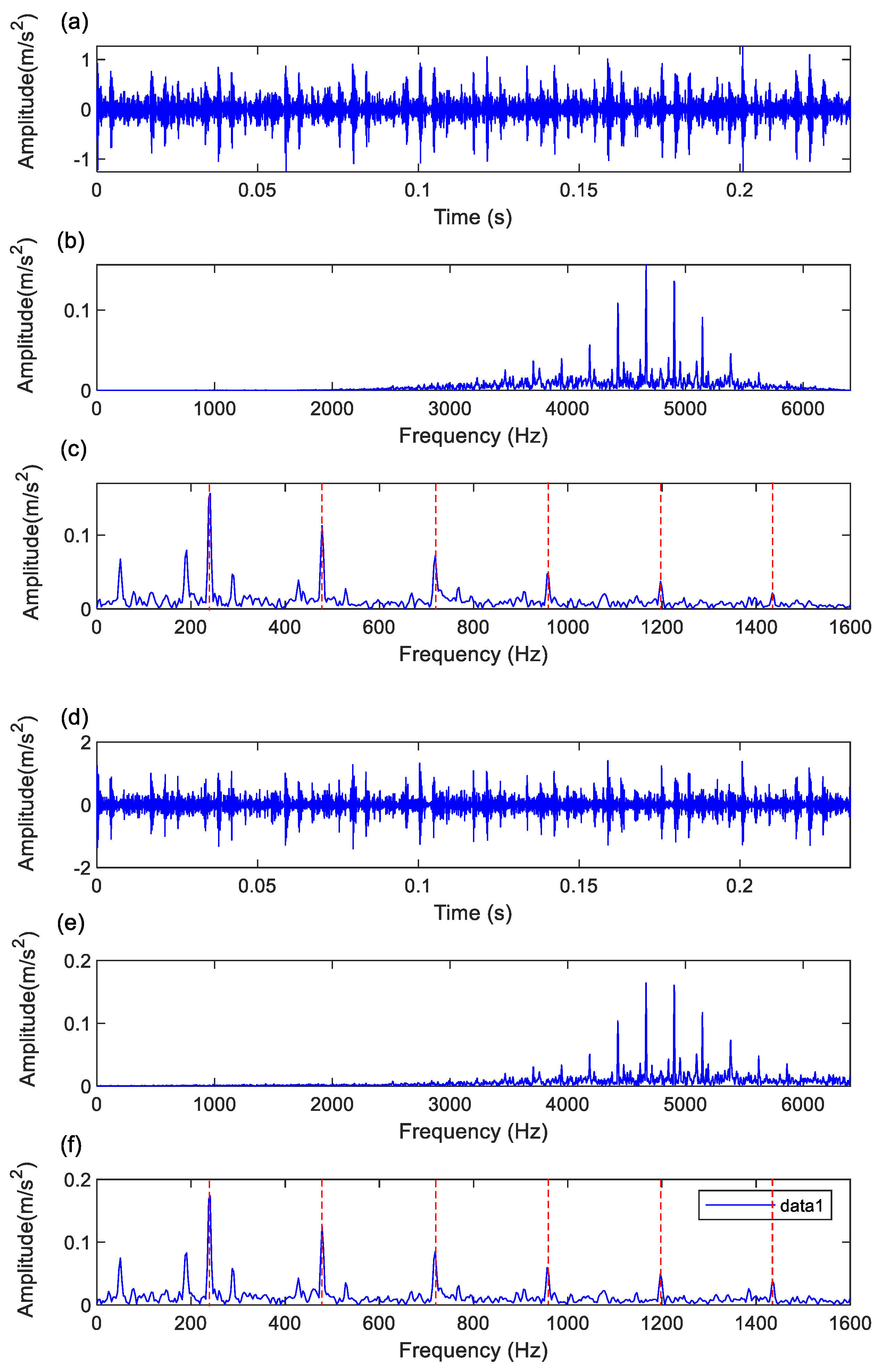
Figure 5.
The test rig picture.
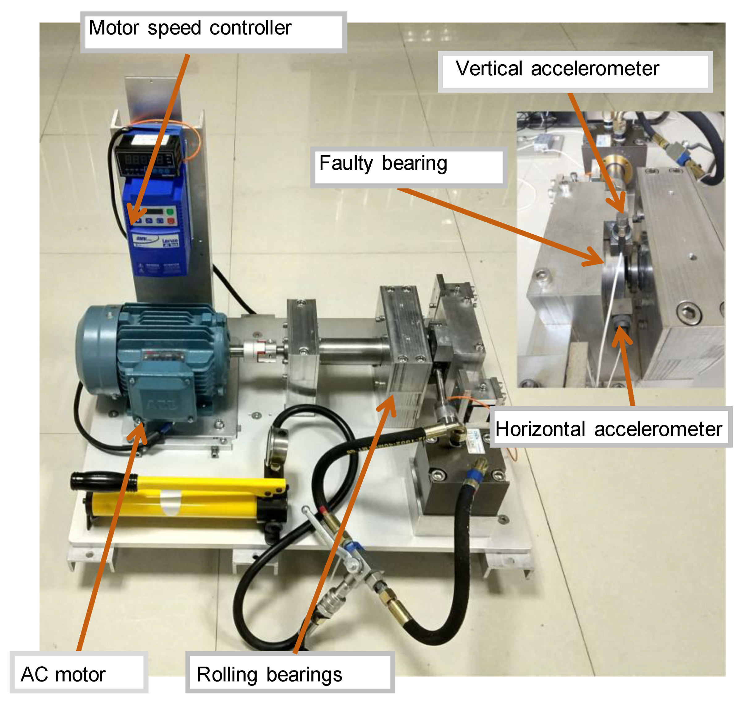
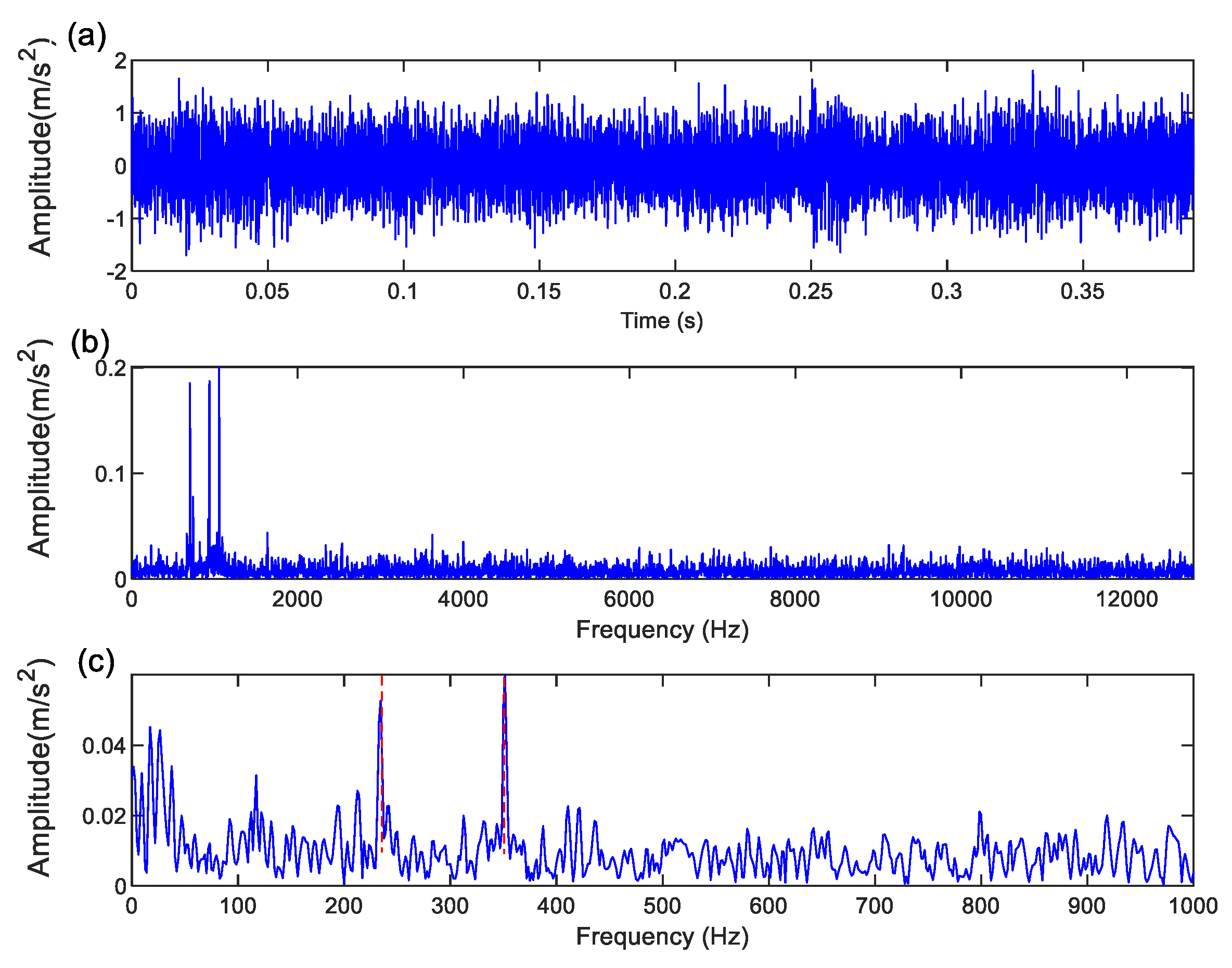
Figure 6.
The original bearing experimental signal in time domain and frequency domain: (a) Signal waveform for the horizontal accelerometer; (b) Spectrum for the horizontal accelerometer; (c) Envelope spectrum for the horizontal accelerometer; (d) Signal waveform for the vertical accelerometer; (e) Spectrum for vertical accelerometer; (f) Envelope spectrum for vertical accelerometer.
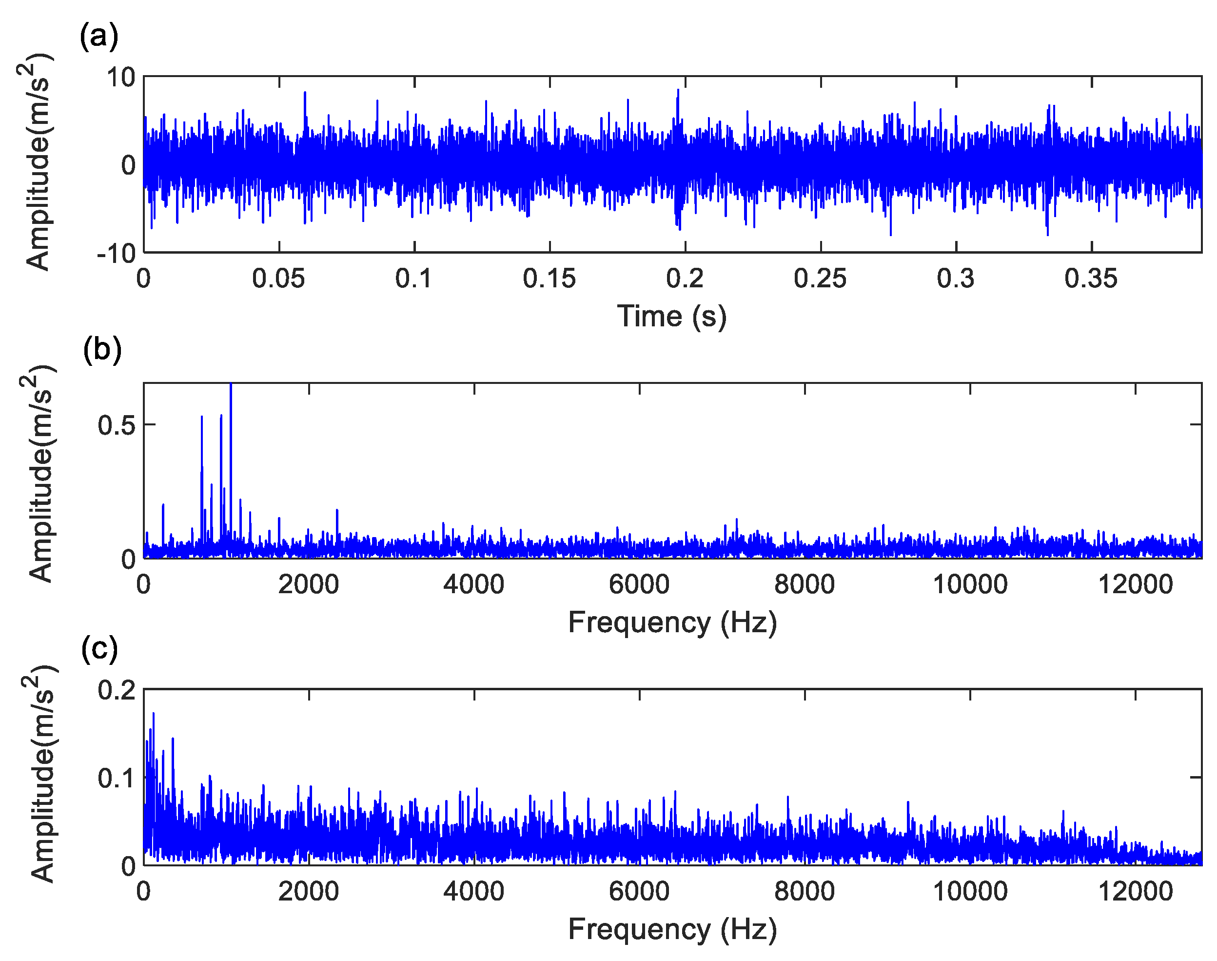
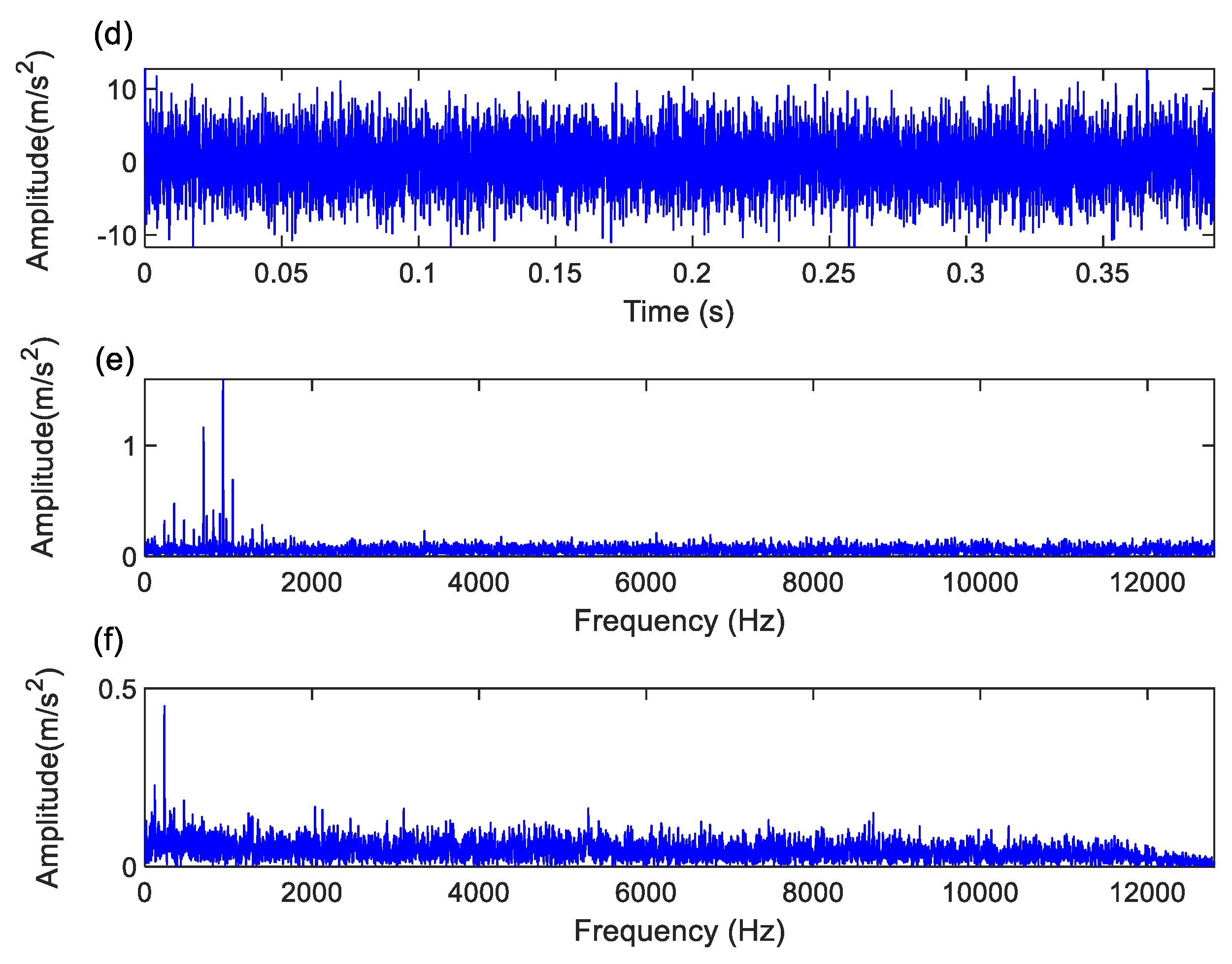
Figure 7.
The processing components for the experimental signal using the proposed method: (a) Signal waveform for the horizontal accelerometer; (b) Spectrum for the horizontal accelerometer; (c) Envelope spectrum for the horizontal accelerometer; (d) Signal waveform for the vertical accelerometer; (e) Spectrum for vertical accelerometer; (f) Envelope spectrum for vertical accelerometer.
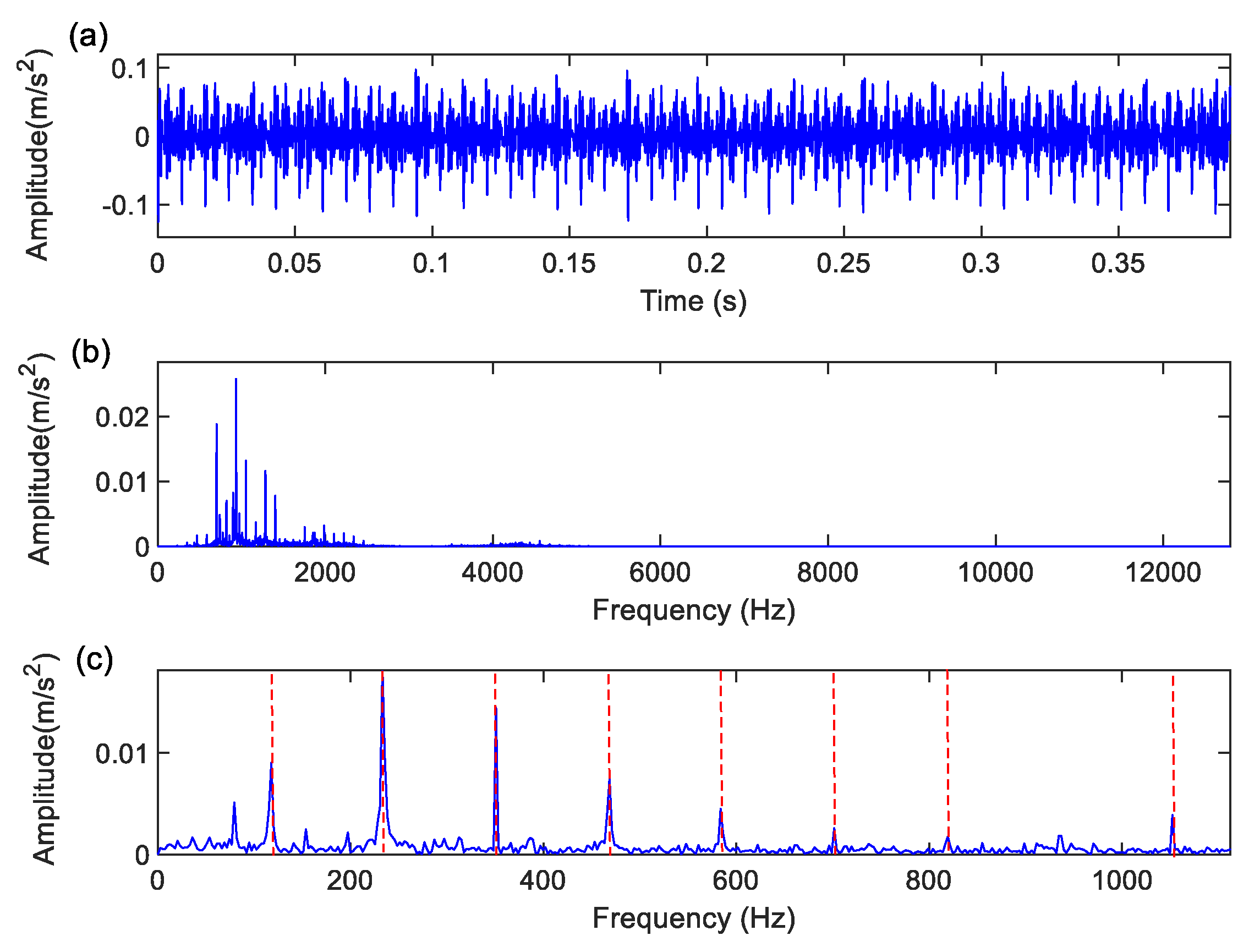
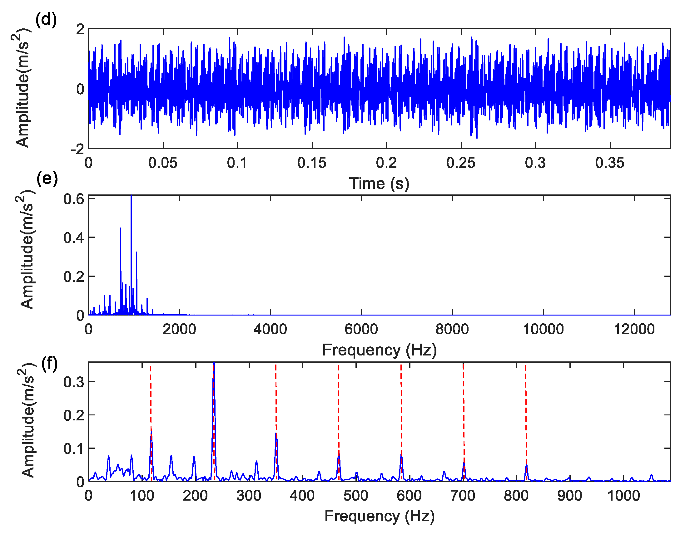
Figure 8.
The processing results of the experimental signal using the TRPCA: (a) Signal waveform for the horizontal accelerometer; (b) Spectrum for the horizontal accelerometer; (c) Envelope spectrum for the horizontal accelerometer; (d) Signal waveform for the vertical accelerometer; (e) Spectrum for vertical accelerometer; (f) Envelope spectrum for vertical accelerometer.

Disclaimer/Publisher’s Note: The statements, opinions and data contained in all publications are solely those of the individual author(s) and contributor(s) and not of MDPI and/or the editor(s). MDPI and/or the editor(s) disclaim responsibility for any injury to people or property resulting from any ideas, methods, instructions or products referred to in the content. |
© 2024 by the authors. Licensee MDPI, Basel, Switzerland. This article is an open access article distributed under the terms and conditions of the Creative Commons Attribution (CC BY) license (https://creativecommons.org/licenses/by/4.0/).
Copyright: This open access article is published under a Creative Commons CC BY 4.0 license, which permit the free download, distribution, and reuse, provided that the author and preprint are cited in any reuse.


