
Submitted:
03 December 2024
Posted:
05 December 2024
You are already at the latest version
Abstract
Hybrid processes of additive and subtractive manufacturing offer designers the potential to develop complex, lightweight parts by additive manufacturing coupled with superior surface quality and tolerance by subsequent machining. The thin-walled additive structures tend to deflect while machining due to static and dynamic effects. With the design for additive manufacturing, additional stiffening structures can be included to reduce vibrations. This work investigates the design of additively manufactured stiffening structures for vibration reduction in the milling of thin-walled parts. A vibration analysis of a probe geometry is simulatively performed to identify significant design parameters. From the outer dimensions, the height of a stiffening structure shows the highest influence, followed by the length. With larger stiffening structures, the mass rises, so a tradeoff between deformation reduction and additional material is necessary. Over the parameters length, width, and height, the deformation can be reduced by a factor of 800 while a mass increase of 4.82 %. Stiffening structures shall be positioned against the excitation direction of the milling force. Over the parameters quantity, position, and distance, a deformation reduction of 185 for a mass increase of 7.11 % can be realized. The paper concludes with design guidelines for additively manufactured stiffening structures.
Keywords:
Powder bed fusion of metals using a laser beam (PBF-LB/M)
; design for additive manufacturing (DfAM)
; hybrid manufacturing
; machining
; vibration reduction
Introduction
Additive manufacturing (AM) offers, due to its layer-wised and tool-free production, great design freedoms for highly complicated parts that are difficult or impossible to manufacture with conventional processes [1,2,3]. One of the leading metallic AM processes is the powder bed fusion of metals using a laser beam (PBF-LB/M). This technique enables the production of high-performance, complex metallic parts with a lightweight design that makes it attractive for the aerospace industry [4,5]. Nevertheless, the manufactured parts are limited in accuracy and surface quality [6]. Residual stresses due to rapid cooling lead to warpage and geometrical deviations [7]. In addition, the accuracy is limited due to the appearance of staircase effects resulting from the layer-wised production [6]. The surface roughness strongly depends on the part’s orientation in the build volume; a typical arithmetic mean value of PBF-LB/M samples lies at about 25 µm Ra [8,9,10]. Parts’ functional surfaces often need accurate dimensional and surface qualities, so post-processing with milling or grinding processes is necessary [11,12].
The combination of additive and subtractive manufacturing is known as hybrid manufacturing (HM) [13]. HM processes are standard practice for additively manufactured metal products when surface quality, narrowed dimensional tolerances, and avoidance of the risk of excessive stresses are required [14]. PBF-LB/M can be combined with CNC milling to solve production obstacles of complex shapes with high accuracy of functional surfaces under required surface quality and build speed [14,15]. The HM process can produce complex thin-walled products that appear, e.g., in the aircraft [16] and are impossible to obtain with conventional manufacturing. Nevertheless, the machining of AM parts can be challenging due to the low stiffness and damping of lightweight, thin-walled parts with high complexity [17,18]. Vibrations between the tool and the part with high amplitudes can occur while milling, especially in lower frequencies under 1,000 Hz [18,19,20,21,22]. The low modal frequencies of thin-walled structures lead to the excitation of resonances via the milling forces [19]. This can lead to damage on the surface, dimensional deviations, and low surface qualities [21,23,24]. To reduce vibrations, thin-walled parts are machined with conservative process parameters, leading to low material removal rates and inefficient processes [25].
The design for additive manufacturing (DfAM) enables the integration of elements for the subsequent machining operations. Specific fixtures and orientation setups for complex parts under high accuracy requirements can be integrated directly into the additively manufactured part with less effort than conventional manufacturing [26,27]. For example, referencing, clamping, and positioning elements for the machining can be connected with the part [17,28]. Figure 1 shows the PBF-LB/M process for a hybrid part, which is machined afterward. The part is extended with referencing and clamping elements for the milling machine to identify zero points and an easy clamp with standard fixtures. The additional structures must be removed after the machining operation [17]. The reduction of machining vibrations is one of the main objectives. The standard approach is to machine the AM part on the build platform with support structures [29,30]. This enables easy clamping, but the accessibility of downskin surfaces is terrible [29]. Redesigning additively manufactured support structures as fixtures and for vibration reduction is common because specific clamps are unnecessary [26,30]. Didier et al. [30] investigate support structures for fixation and vibration reduction in end milling operations of thin-walled parts. Face milling tests on plates manufactured by PBF-LB/M show that the displacement amplitude decreases to 0.31 mm and the surface roughness Ra decreases to 0.11 µm with stiffer support structures [30]. In contrast, the cutting force amplitude increases to 83.1 N [30]. The vibration reduction and surface improvement results from the growing distance between modal and excitation frequency [30]. The higher cutting force amplitude indicates a lower workpiece deflection and better dimensional accuracy [30]. Nevertheless, support structures can only be used when the position and orientation of the AM part permit it. The tool’s accessibility while machining must be ensured; downskin surfaces or surfaces under support structures are inaccessible [29]. In addition to support structures, additional stiffening structures can be designed to reduce vibration and increase stiffness and stability [31]. Smith et al. [31] investigate stiffening structures for milling thin-walled parts. Different variants are designed and analyzed on a wall probe by finite element analysis [31]. The highest stiffness increase by a factor of 7.7 is achieved with triangle ribs placed on both opposite long sides of the wall geometry [31]. In a milling test, they prove a more stable process and an improvement in surface quality [31]. In summary, the first studies show the effectiveness of stiffening structures for vibration reduction in milling. However, further investigation is needed to analyze different stiffening structures and give appropriate design guidelines for the application. Understanding and considering the machining vibrations in the design phase of additively manufactured parts is necessary.
This study aims to determine design guidelines for additively manufactured stiffening structures to reduce vibrations in milling. Therefore, a probe geometry is selected in a design study, and then different stiffening structure design parameters are analyzed using numerical simulations. The deformation of the probe geometry and the additional mass shall be minimized to enable an efficient milling process with fewer vibrations and low production effort. The influence factors of design parameters are determined so that a prediction of actual vibration behavior with stiffening structures can be made, and an optimal solution for a particular application is given. With the results of the design parameters, design guidelines are derived.
2. Materials and Methods
2.1. Probe Geometry and Machining Operation
In order to describe the behavior of different design parameters of stiffening structures to the resulting vibrations and mass, a generalized, simplified probe geometry is needed. A thin-walled part similar to the probe geometry in [31] is used for that case. The investigated model with dimensions is shown in Figure 2 a) and consists of four parts. A base plate is considered as a fixed body that simulates a fixed support as a clamping system. On top of the base plate, a support structure is placed, which symbolizes an intermediate volume body between the part and the base plate, analogous to the additive manufacturing process. Then, a thin-walled part is placed above the support structure, which is the final product with a length of 30 mm, width of 4 mm, and height of 85 mm. The red marked surface stands for the machining surface, which will be machined by a milling tool. A green marked design space is defined on the opposite of the machining surface. The maximum dimensions result from the part’s geometry and the depth above the base plate. So, a maximum length of 33 mm, width of 30 mm, and height of 90 mm is defined. Different stiffening structures are integrated into this space and analyzed to identify the ideal stiffness enhancement and vibration reduction geometry.
For this investigation, a finishing process of the additively manufactured part is assumed at the above shown machining surface by an end mill. The tool is assumed to be sufficiently stiff, so it can be idealized to a uniaxial milling force that excites the thin-walled part. Synchronous milling is assumed, a milling force normal to the thin-walled part surface appears and presses the part away from the end mill so that an inadequate chip removal can appear [19,32]. The milling force position, orientation, and condition of intervention are held constant in this case. Due to the low intervention in the finishing process, the main work is performed over the circumferential cutting edges so that the process can be assumed as a circumferential milling [19]. For the analysis, an end mill CoroMill® Dura from Sandvik Tooling Deutschland GmbH with four cutting edges, a diameter of 6 mm, and a swirl angle of 35.5° is defined. The manufacturer gives this tool a spindle rotation speed of 5790 1/min. Over the equation , an excitation frequency of 386 Hz results. For the cutting force, a value of 150 N is assumed. The force will be set in the middle of the machining surface, and the direction will be assumed equal to the middle intervention, which is defined over
For an inlet intervention of 71.8° and an outlet intervention of 90°, a middle intervention and force direction of 170.9° result. As a material for the thin-walled part, stainless steel with the number 1.4404, also known as 316L and typical for additive manufacturing, is assumed.
2.2. Design Parameter Study
In a two-series design study, the factors that influence vibration reduction with stiffening structures shall be identified and quantified to ensure a good surface quality of the machined surface of the final part. Therefore, the displacement of the part orthogonal to the feed direction has to be minimized so that a low deviation of the milling path and a low surface roughness from vibrations result. The addition of stiffening volume results in increased material demand in the AM and higher production costs. So, the second target is the minimization of additional mass for economic production. The calculation time rises with the increased number of design parameters, so six design parameters are investigated in a two-series design study. In the first study, a prism in a triangle shape is analyzed for its outer dimensions (see Figure 3 a). The prism is bonded at the opposite surface of the machining surface of the thin-walled part and the base plate. The length l, width w, and height h are varied up to the maximum design space of 33 mm, 30 mm, and 90 mm (in l × w × h). The minimum is defined as 1 and 5 mm, as smaller dimensions are assumed to have a negligible influence on vibration reduction. In the second study, triangle shaped ribs with 30 × 2 × 30 (l × w × h) mm3 dimensions and constant distance to each other are analyzed. The position p, distance d, and quantity n of the ribs are varied (see Figure 3 b). For the quantity, up to 11 ribs are investigated. The position is 0 when the centered rib aligns with the back end of the wall and 28 when the centered rib aligns with the front end. The distance between the ribs is between 3 and 15 mm, as 3 indicates a gap of 1 mm between them. The ribs are bonded at the thin-walled part and the base plate. A design of experiment (DoE) with the sampling method “Latin Hypercube sampling” is applied to define the design points in the design space.
2.3. Vibration Analysis of a Machined Surface
For the analysis of the design study, a parametric model and a simulation are performed. A parametric model is built up in Inventor Professional 2023 from Autodesk Inc. This model is transferred to a Workbench 2023 R2 project from Ansys Inc., in which a harmonic response analysis is conducted to simulate the vibrations while milling. The material “316 stainless steel” from the material data source “additive manufacturing materials” is selected for all bodies of the model, which lies within the range of a material data sheet for AM 316L [33]. All bodies are bonded at their contact surfaces to simulate a material-locking melting process in the PBF-LB/M process. As a mesh, an element size of 3 mm is defined, while the element size for the support structures is 1 mm. A fixed support is applied at the bottom surface of the base plate (see Figure 2 b) as a simplification. A sine force signal is applied; this can be assumed for milling processes with excitation frequencies over 100 Hz [19]. The system vibrates with the excitation frequency of 386 Hz, as calculated in Section 2.1. The force curve while cutting intervention and the phase offset due to asymmetry can be neglected [19]. For the force excitation, a quadratic surface on top and in the middle of the wall tip is selected, centered in the machining surface to neglect edge effects, which often occur in the side milling of thin-walled parts [34]. Then, the force of 150 N with an excitation angle of 170.9° is defined. As a result of the simulation, the maximum orthogonal deformation relative to the feed direction and the mass is calculated. The model is simulated for each design point in the DoE. With the results, a response surface is calculated and used for a multi-objective optimization to determine the tradeoff between the minimization of deformation and mass. The multi-objective genetic algorithm (MOGA) is used as an optimization method to generate a design point population and find the global minimum in the optimization domain.
3. Results
The probe geometry from Section 2.1 is first analyzed without any stiffening structures. A maximum deformation results in 16.162 mm at the tip of the wall. The mass of the geometry lies at 0.2808 kg.
3.1. Length, Width and Height of Stiffening Structures
The response surfaces of the design parameters length, width, and height are shown in Figure 4. As can be seen, the parameters influence each other for the resulting maximum deformation. The maximum deformation decreases with l, w, and h increase. The combined minimum (red dot) is located when l, w, and h go toward the maximum dimensions; the resulting deformation is -0.00445 mm. The maximum deformation is 1.633 mm for the minimum dimensions of the structure. The gradient of the response surface indicates the influence on deformation reduction. The height h achieves the largest gradient, so this parameter shows the most significant influence. The length l shows a larger gradient than the width w, indicating that l is more significant than w.
Nevertheless, with increasing dimensions, the additional mass also rises. The multi-objective optimization results in a Pareto front, as shown in Figure 5 a). The optima are located along a curve and can differ over the target of deformation and mass. One of the optimum candidate points is shown in Figure 5 b) (the red circle in Figure 5 a). An optimum stiffening structure is designed as a prism with l = 13.85 mm, w = 2.35 mm, and h = 88.96 mm. The deformation lies at about 0.0202 mm, while the additional mass is -0.01423 kg. This indicates that the deformation can be reduced by a factor of 800 when the mass is increased by 4.82%.
3.2. Position, Distance and Quantity Of Stiffening Structures
The response surfaces of the design parameters position, distance, and quantity are shown in Figure 6. The parameters influence each other for the deformation as well. As can be seen, the maximum deformation is 0.1597 mm, while the minimum is 0.07329 mm. The deformation decreases slightly with increasing quantity, and for the position and distance, a local minimum (red dot) can be found at p = 10 mm and d = 5 mm. The deformation increases for low and high p values because, at a particular position, the ribs lose their connection to the wall. The maximum deformation for n = 11 and d = 3 mm is not expected, and by a simulation of this parameter combination, an error in generating the response surface is approached.
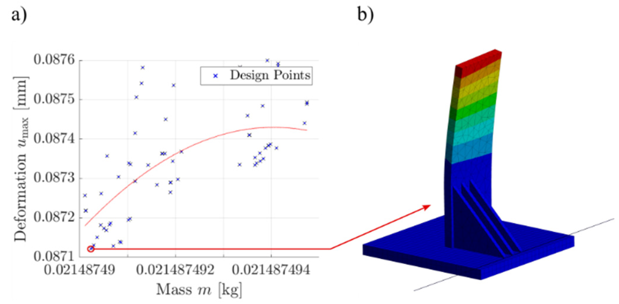
The mass increases with more ribs but is constant over the position and distance. The multi-objective optimization in Figure 7 a) shows that an optimum exists for minimizing deformation and mass. This is shown in Figure 7 b) for n = 3, p = 20.27 mm and d = 6.154 mm. The ribs are placed eccentrically and on the side of the wall in which the force acts. The optimum results in a deformation of 0.08713 mm, while the mass lies at about 0.02149 kg. This indicates a deformation reduction by 185 when the mass is increased by 7.11%.
4. Discussion—Design Guidelines of Stiffening Structures
4.1. Length, Width and Height Of Stiffening Structures
The parameters l, w, and h influence the deformation and mass due to stiffness and volume changes. A minimum deformation appears when these parameters are maximized, so the stiffness increases and the modal frequency rises, resulting in a greater distance to the excitation frequency. In the response surface in Figure 4, a negative deformation is achieved. This results from the deviations between the interpolated response surface and the DoE; a value near zero can be assumed. The height h shows the highest influence and shall be maximized so that the stiffening structure is located near the excitation area. The length l is also relevant; more material is placed along the excitation, so this parameter shall be maximized as much as possible. The width w is less relevant and can be designed small under the requirement to ensure sufficient stability, for example, in the AM. With the 3D diagrams, a design parameter combination for a stiffening structure can be found, which ensures a maximum deformation below a specific value, e.g., 3.2 µm, which is typical for functional surfaces. The maximum deformation can be decreased to near zero by a factor of 3,632, leading to a mass increase of up to 109.5%. Multi-objective optimization proves the impact of the design parameters and gives the designer a diagram to find a tradeoff between deformation and mass. In order to reduce vibrations with less material addition, a stiffening structure with a medium length, trim width, and significant height can be used.
4.2. Position, Distance and Quantity of Stiffening Structures
The parameters p, d, and n influence the deformation and are relevant for vibration reduction. The higher quantity of stiffening structures reduces deformation due to more material and stiffness, but for n > 3, the impact is relatively low. For the position, the local minimum proves that the ribs shall be placed against the excitation direction. The distance shows a local minimum of 5 to 6.5 mm, which indicates that a compromise is found when the ribs are concentrated near the critical displacement, act as a single volume, and increase the general stiffness of the structure. Also, with the 3D diagrams, a design parameter combination for a particular application can be found. The maximum deformation can be decreased up to a factor of 220.5 but with a mass increase of about 21.89%. This indicates less impact on the deformation reduction, but the ribs’ outer dimensions are defined with 30 × 2 × 30 mm3 (l × w × h); when the dimensions are adapted to the optimum values of the first design study, a higher impact is possible. The multi-objective optimization shows that three ribs are sufficient for deformation reduction in this application. In addition, the position proves that the stiffening structures shall be placed against the excitation direction of the end mill, so the resulting milling force is significant for the design of stiffening structures. In this study, the rotation of stiffening structures is still not investigated, but a relation is hypothesized.
5. Conclusions and Outlook
In this paper, design guidelines for additively manufactured stiffening structures are developed to reduce vibrations in milling. A thin-walled probe geometry is designed and analyzed for an assumed face milling process on the above side of the face of the part. A prism and several ribs are placed in a design space and investigated in a two-series design study. A harmonic simulation is conducted while the design parameters length, width, and height of the prism and the position, distance, and quantity of ribs are analyzed. With a design of experiment, parameter combinations are simulated and used to calculate response surfaces. A multi-objective optimization is applied to determine the optimality for minimizing deformation and mass. The deformation decreases with larger length, width, and height due to higher stiffness, while the mass increases due to larger volumes; a tradeoff is necessary. The height shows the highest impact, so stiffening structures near the excitation area shall be designed. The length is relevant to place more material along the excitation direction. The width has a low impact on deformation and can be designed material-savened. With the response surfaces, designers can find an appropriate stiffening structure for their application. The multi-objective optimization results in a medium length, small width, and large height of the stiffening structure, which reduces the deformation by a factor of 800 by a mass increase of about 4.82% compared to the probe geometry. The increased quantity of ribs reduces the deformation due to higher stiffness, but the mass increases with more ribs. An optimum position is found when the ribs are placed against the excitation direction. For the distance, an optimum of 5 to 6.5 mm shows that a compromise is found. The multi-objective optimization results in three ribs placed against the excitation direction with a distance of 6.154 mm, which decreases the deformation by 185 while the mass increases by 7.11% compared to the probe geometry. In this study, the first design guidelines for additively manufactured stiffening structures to reduce vibrations in milling are developed, but further research is still open. The results of these simulations need verification tests on a real milling machine. As indicated, more design parameters are present. For example, the milling force vector is decisive for the design of stiffening structures. The orientation and shape of stiffening structures are relevant as well. In addition, the part geometry plays a significant role and needs further investigation.
Acknowledgements
The project “Methodology for optimizing the interactions between additive and machining manufacturing“ was funded by the Deutsche Forschungsgemeinschaft (DFG, German Research Foundation) – project number 513747002.
References
- Lachmayer, R.; Ehlers, T.; Lippert, R.B. Design for Additive Manufacturing; Springer: Berlin, Heidelberg, 2024. [Google Scholar] [CrossRef]
- Wahl, J.P.; Niedermeyer, J.; Bernhard, R.; Hermsdorf, J.; et al. Design of additively manufacturable injection molds with conformal cooling. 2022, 111, 97. [Google Scholar] [CrossRef]
- Ehlers, T.; Meyer, I.; Oel, M.; Bode, B.; et al. Effect-Engineering by Additive Manufacturing. p. 1. [CrossRef]
- Campbell, I.; Bourell, D.; Gibson, I. Additive manufacturing: rapid prototyping comes of age. 2012, 18, 255. [Google Scholar] [CrossRef]
- Niedermeyer, J.; Ehlers, T.; Lachmayer, R. Potential of additively manufactured particle damped compressor blades: A literature review. 2023, 119, 570. [Google Scholar] [CrossRef]
- Abdulhameed, O.; Al-Ahmari, A.; Ameen, W.; Mian, S.H. Additive manufacturing: Challenges, trends, and applications. 2019, 11, 168781401882288. [Google Scholar] [CrossRef]
- Mugwagwa, L.; Dimitrov, D.; Matope, S.; Yadroitsev, I. Influence of process parameters on residual stress related distortions in selective laser melting. 2018, 21, 92. [Google Scholar] [CrossRef]
- Simonelli, M.; Tse, Y.Y.; Tuck, C. Effect of the build orientation on the mechanical properties and fracture modes of SLM Ti-6Al-4V. 2014, 616, 1. [Google Scholar] [CrossRef]
- Leary, M. Surface roughness optimisation for selective laser melting (SLM). In Laser Additive Manufacturing; Elsevier, 2017; p. 99. [Google Scholar] [CrossRef]
- Rott, S.; Ladewig, A.; Friedberger, K.; Casper, J.; et al. Surface roughness in laser powder bed fusion – Interdependency of surface orientation and laser incidence. 2020, 36, 101437. [Google Scholar] [CrossRef]
- Brinksmeier, E.; Levy, G.; Meyer, D.; Spierings, A.B. Surface integrity of selective-laser-melted components. 2010, 59, 601. [Google Scholar] [CrossRef]
- Waldschmidt, J.; Lindecke, P.; Wichmann, M.; Denkena, B.; et al. Improved Machining of Additive Manufactured Workpieces Using a Systematic Clamping Concept and Automated Process Planning. 2020. [Google Scholar]
- Du, W.; Bai, Q.; Zhang, B. A Novel Method for Additive/Subtractive Hybrid Manufacturing of Metallic Parts. 2016, 5, 1018. [Google Scholar] [CrossRef]
- GRZESIK, W.; Ruszaj, A. Hybrid Manufacturing Processes: Physical Fundamentals, Modelling and Rational Applications, 1st ed.; Springer International Publishing: Cham, 2021. [Google Scholar] [CrossRef]
- Choi, D.-S.; Lee, S.; Shin, B.; Whang, K.; et al. Development of a direct metal freeform fabrication technique using CO2 laser welding and milling technology. 2001, 113, 273. [Google Scholar] [CrossRef]
- Ding, D.; Shen, C.; Pan, Z.; Cuiuri, D.; et al. Towards an automated robotic arc-welding-based additive manufacturing system from CAD to finished part. 2016, 73, 66. [Google Scholar] [CrossRef]
- Jiménez, A.; Bidare, P.; Hassanin, H.; Tarlochan, F.; et al. Powder-based laser hybrid additive manufacturing of metals: a review. 2021, 114, 63. [Google Scholar] [CrossRef]
- Maslo, S.; Menezes, B.; Kienast, P.; Ganser, P.; et al. Improving dynamic process stability in milling of thin-walled workpieces by optimization of spindle speed based on a linear parameter-varying model. 2020, 93, 850. [Google Scholar] [CrossRef]
- Klocke, F. Fertigungsverfahren 1; Springer: Berlin, Heidelberg, 2018. [Google Scholar] [CrossRef]
- Michalik, P.; Zajac, J.; Hatala, M.; Mital, D.; et al. Monitoring surface roughness of thin-walled components from steel C45 machining down and up milling. 2014, 58, 416. [Google Scholar] [CrossRef]
- Denkena, B.; Tönshoff, H.K. Spanen: Grundlagen, 3rd ed.; Springer: Berlin, Heidelberg, 2011. [Google Scholar]
- Altintas, Y.; Kersting, P.; Biermann, D.; Budak, E.; et al. Virtual process systems for part machining operations. 2014, 63, 585. [Google Scholar] [CrossRef]
- Seguy, S.; Dessein, G.; Arnaud, L. Surface roughness variation of thin wall milling, related to modal interactions. 2008, 48, 261. [Google Scholar] [CrossRef]
- Byrne, G.; Dornfeld, D.; Denkena, B. Advancing Cutting Technology. 2023, 52, 483. [Google Scholar] [CrossRef]
- Abele, E.; Dohnal, F.; Feulner, M.; Sielaff, T.; et al. Numerical investigation of chatter suppression via parametric anti-resonance in a motorized spindle unit during milling. 2018, 12, 309. [Google Scholar] [CrossRef]
- Lachmayer, R.; Ehlers, T.; Lippert, R.B. Entwicklungsmethodik für die Additive Fertigung; Springer: Berlin, Heidelberg, 2022. [Google Scholar] [CrossRef]
- Manogharan, G.; Wysk, R.; Harrysson, O.; Aman, R. AIMS—A Metal Additive-hybrid Manufacturing System: System Architecture and Attributes. 2015, 1, 273. [Google Scholar] [CrossRef]
- Beutler, P.; Ferchow, J.; Schlüssel, M.; Meboldt, M. Semi-Automated Design Workflow for Bolt Clamping Interfaces to Post-Process Additive Manufactured Parts. 2023, 119, 596. [Google Scholar] [CrossRef]
- Maucher, C.; Kordmann, L.; Möhring, H.-C. Design Rules for the Additive-Subtractive Process Chain. 2023, 119, 1115. [Google Scholar] [CrossRef]
- Didier, P.; Le Coz, G.; Robin, G.; Lohmuller, P.; et al. Consideration of SLM additive manufacturing supports on the stability of flexible structures in finish milling. 2021, 62, 213. [Google Scholar] [CrossRef]
- Smith, S.; Wilhelm, R.; Dutterer, B.; Cherukuri, H.; et al. Sacrificial structure preforms for thin part machining. 2012, 61, 379. [Google Scholar] [CrossRef]
- Schmitz, T.L.; Smith, K.S. Machining Dynamics; Springer International Publishing: Cham, 2019. [Google Scholar] [CrossRef]
- m4p material solutions GmbH, 2024. m4p 316L: Technical Data Sheet.
- Thevenot, V.; Arnaud, L.; Dessein, G.; Cazenave-Larroche, G. Integration of dynamic behaviour variations in the stability lobes method: 3D lobes construction and application to thin-walled structure milling. 2006, 27, 638. [Google Scholar] [CrossRef]
Figure 1.
Schematic view of the PBF-LB/M process for a hybrid part with machining elements.
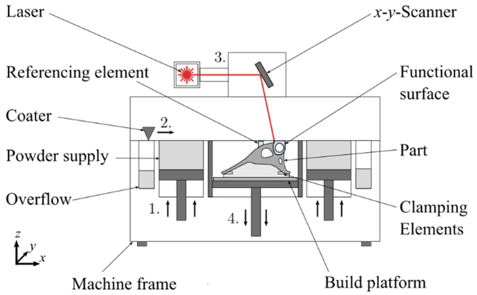
Figure 2.
(a) CAD-model of the probe geometry with dimensions and (b) boundary conditions for the harmonic analysis.
Figure 2.
(a) CAD-model of the probe geometry with dimensions and (b) boundary conditions for the harmonic analysis.
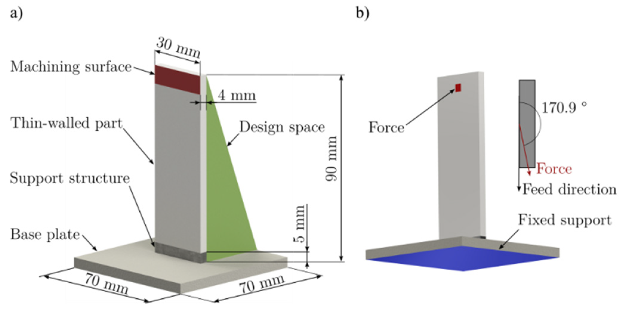
Figure 3.
Models for the two series studies: a) first design study with parameters l, w and h; b) second design study with parameters n, p and d.
Figure 3.
Models for the two series studies: a) first design study with parameters l, w and h; b) second design study with parameters n, p and d.
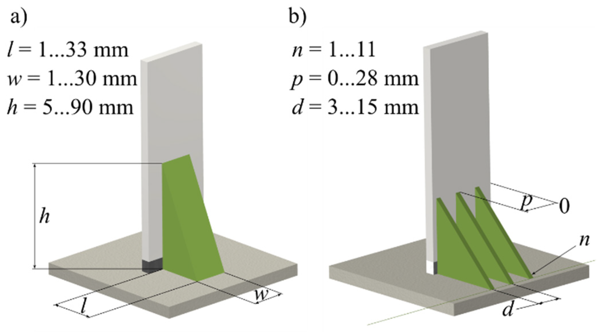
Figure 4.
Response surfaces for the deformation umax over the parameters length l, width w and height h.
Figure 4.
Response surfaces for the deformation umax over the parameters length l, width w and height h.
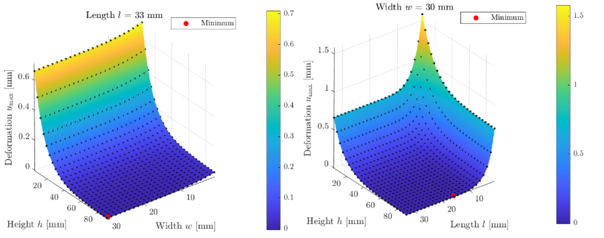
Figure 5.
a) Multi-objective optimization for maximum deformation and mass and b) example of an optimal candidate point.
Figure 5.
a) Multi-objective optimization for maximum deformation and mass and b) example of an optimal candidate point.
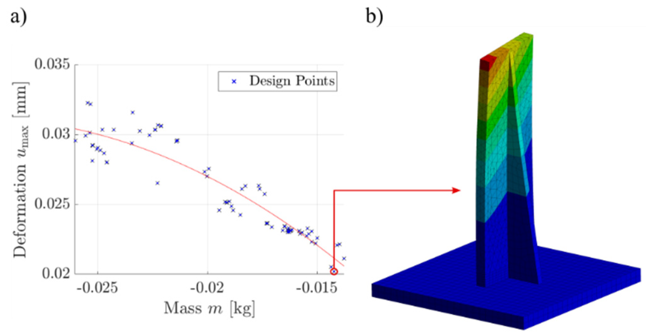
Figure 6.
Response surfaces for the deformation umax over the parameters position p, distance d and quantity n.
Figure 6.
Response surfaces for the deformation umax over the parameters position p, distance d and quantity n.
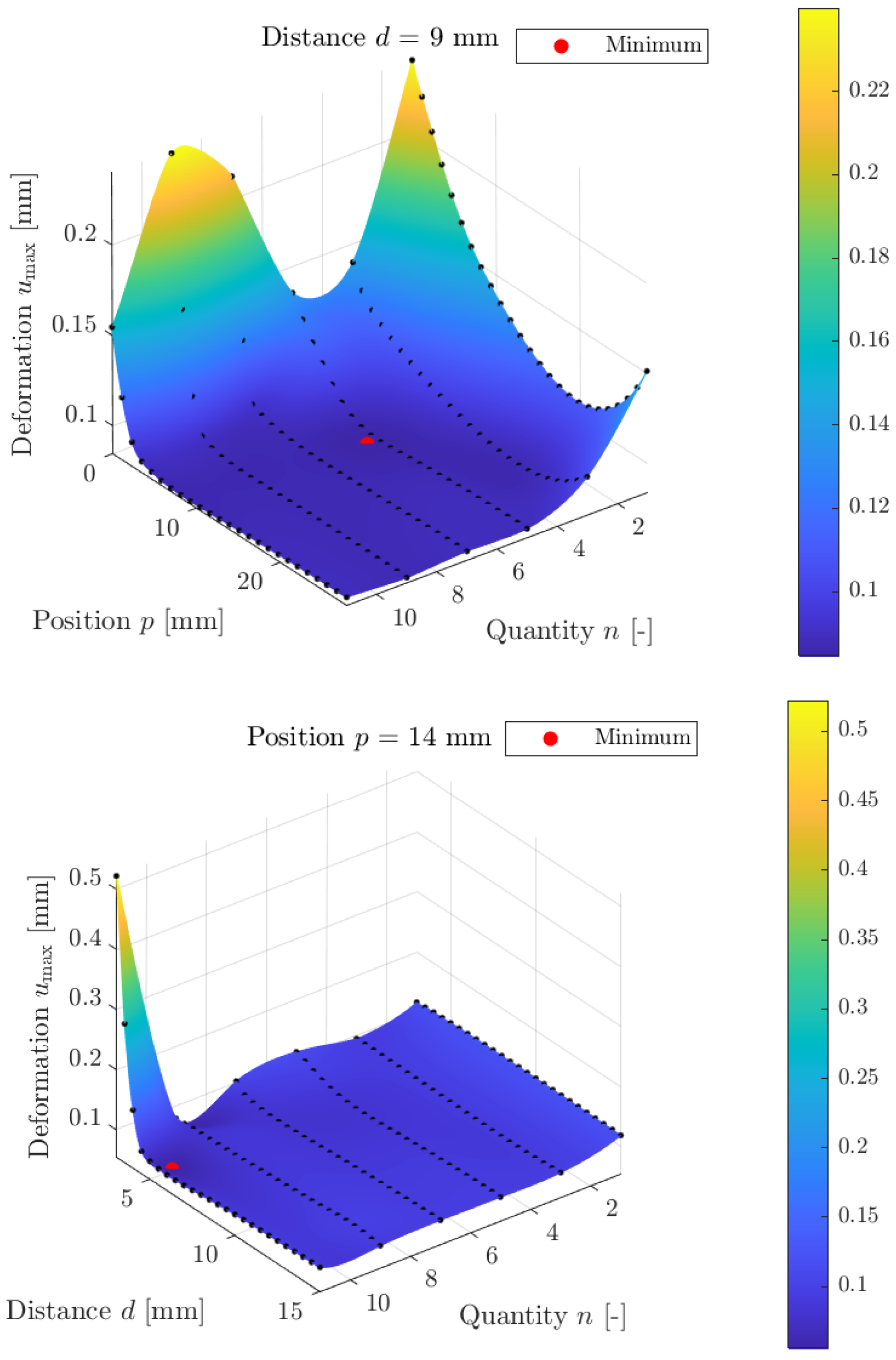
Figure 7.
a) Multi-objective optimization for deformation and mass and b) optimal candidate point.
Disclaimer/Publisher’s Note: The statements, opinions and data contained in all publications are solely those of the individual author(s) and contributor(s) and not of MDPI and/or the editor(s). MDPI and/or the editor(s) disclaim responsibility for any injury to people or property resulting from any ideas, methods, instructions or products referred to in the content. |
© 2024 by the authors. Licensee MDPI, Basel, Switzerland. This article is an open access article distributed under the terms and conditions of the Creative Commons Attribution (CC BY) license (http://creativecommons.org/licenses/by/4.0/).
Copyright: This open access article is published under a Creative Commons CC BY 4.0 license, which permit the free download, distribution, and reuse, provided that the author and preprint are cited in any reuse.


