Submitted:
02 December 2024
Posted:
02 December 2024
Read the latest preprint version here
Abstract
Introduction:
The biological response to hernia prostheses remains a topic of ongoing debate. Traditional static hernia meshes, widely used to reinforce the herniated abdominal wall, often lead to poor-quality fibrotic tissue ingrowth, mesh shrinkage, and complications such as nerve entrapment. These issues are particularly problematic in groin hernia repairs, where scar tissue can impair movement and cause discomfort. To address these challenges, the dynamic Stenting & Shielding (S&S) Hernia System was developed, promoting a probiotic biological response that supports the ingrowth of new muscles, nerves, and blood vessels.
Materials and Methods:
This study evaluated the quantity and quality of vascular development within the 3D scaffold of the S&S device implanted in the lower abdominal wall of pigs, with assessments made at various post-implantation stages.
Results:
Early-stage post-implantation revealed extensive angiogenesis within the S&S device excised from the pigs. The quantity and quality of arteries and veins progressively increased, reaching full development from the mid to extra-long term post-implantation. Notably, no inflammatory reactions or stiff scar tissue were observed within the 3D scaffold of the S&S device even long term.
Conclusion:
High quality biological ingrowth in hernia devices requires robust vascular support. The extensive network of mature arteries and veins observed in the S&S Hernia System underscores its regenerative capabilities, making it a promising solution for the treatment of abdominal wall hernias.
Keywords:
Hernia
; abdominal wall
; Experimental research
; Porcine animal model
; Regenerative Scaffolds
; Tissue regeneration
; Regenerative scaffolds
; Arteries
; Veins
; Angiogenesis
1. Introduction
The conventional approach to abdominal wall hernia repair relies on the use of synthetic flat meshes, predominantly made of polypropylene, to reinforce the groin by inducing the ingrowth of a fibrotic scar plate. [1,2] Despite ongoing advancements in techniques and materials, frequent complications continue to affect both intra- and post-operative outcomes, diminishing patient quality of life and increasing healthcare costs. Among the debated causes of these poor outcomes, the uncontrolled and suboptimal biological response of conventional hernia meshes—exacerbated by the challenges of mesh fixation in the highly mobile abdominal wall —plays a significant role. This inadequate response is often linked to unpleasant complications such as postoperative discomfort and chronic pain. [3,4,5,6]
Moreover, the widely accepted term “reinforcement” of the weakened groin may be misleading. The fibrotic ingrowth that is typical of flat, static meshes does not genuinely reinforce the herniated abdominal barrier but instead represents a foreign body reaction. When considering the relationship between this treatment approach and the underlying pathology of hernia protrusion, it becomes clear that conventional flat meshes fail to address the degenerative source of the condition. [7,8,9,10,11,12,13,14] Instead of “reinforcing” the herniated groin with avascular, stiff, and shrunken fibrotic tissue—leaving a patent defect—the goal should be to fill the hernial gap and promote tissue regeneration, thereby fully restoring a competent abdominal barrier.
In response to the motile nature of the abdominal wall and the degenerative pathogenesis of hernia disease, a novel treatment concept has recently emerged. This concept centers on the Stenting & Shielding (S&S) Hernia System, a newly engineered device made from injection-molded polypropylene-based Thermo-Polymer Elastomer (TPE). Unlike conventional flat meshes, this 3D-structured device is designed to be positioned without fixation, effectively obliterating the hernia opening. Its intrinsic dynamic compliance allows it to move in harmony with the abdominal wall, leading to a biological response that is markedly different from that elicited by static meshes.
Experimental investigations on porcine models have demonstrated the regenerative properties of the S&S hernia device, which functions as a regenerative scaffold. Alongside the development of viable connective tissue, the S&S device supports the ingrowth of newly formed muscles and mature nerves. Crucially, to sustain the function of these specialized tissues, the concurrent development and maturation of a suitable vascular network is essential. The present study aims to demonstrate this specific feature at defined stages following the implantation of the S&S hernia device in experimental pigs.
2. Material and Methods
The experimental study was performed in strict accordance with the Animal Care Protocol for Experimental Surgery, as required by the Italian Ministry of Health. Approval for the protocol was granted under Decree No. 379/2021-PR, dated June 1st, 2021. The study is reported in line with the ARRIVE guidelines (Animals in Research: Reporting In Vivo Experiments. [15]
Between February 2022 and July 2024, ten female pigs with bilaterally created muscular defects in the lower abdomen were selected for the study. Each pig received laparoscopic placement of two Stenting & Shielding (S&S) Hernia Devices. The S&S device, designed to allow atraumatic and dissection-free repair of several types of abdominal wall hernias—in particular inguinal, but also incisional, femoral, Spigelian, and obturator hernias—was employed for this purpose.
Aged between 4 and 6 months, the animals had a body weight ranging from 40 to 60 kg. All laparoscopic interventions were carried out under general anesthesia that included premedication with zolazepam and tiletamine (6.3 mg/kg) and xylazine (2.3 mg/kg), followed by induction with propofol (0.5 mg/kg) and maintenance with isoflurane combined with pancuronium (0.07 mg/kg). Postoperative care included antibiotic prophylaxis with oxytetracycline (20 mg/kg/day) for three days.
2.1. Stenting & Shielding Hernia System: Structure
The S&S Hernia System used in this study is fabricated from medical-grade, polypropylene-based Thermo-Polymer Elastomer (TPE). The mechanical properties of the material are presented in Table 1.
The device comprises two main components: an eight-rayed structure contouring a central mast, and a 3D oval shield dimensioned 10x8 cm with a ring positioned at its center. The mast is equipped with a button-like structure at its distal end, along with two conic enlargements (stops) in proximity of the button. Initially, the device is configured as a cylindrical unit, with the oval shield threaded onto the mast via its central ring (Figure 1A & B). This design allows the device to be delivered through a 12 mm trocar into the abdominal cavity. Once positioned inside the hernia defect, a metallic tube is used to advance the oval shield forward into the muscular defect. As the shield is moved beyond one or both conic stops on the mast, the cylindrical rayed structure expands inside the defect, creating an oval 3D scaffold that permanently occupies the hernia opening. This configuration locks the shield, preventing backward slippage, and blocks the scaffold within the defect, with the shield overlapping the muscular opening and making contact with the abdominal viscera (Figure 1C). The final diameter of the 3D scaffold used in this study is approximately 4.5 cm.
2.2. Follow-Up Protocol
Of the 10 pigs, 2 were sacrificed between 4 and 6 weeks postoperatively (short-term period), 2 between 3 and 4 months (mid-term), 5 between 6 and 8 months (long-term), and 1 at 18 months (extra-long-term). Scheduled ultrasound (Figure 1D) and laparoscopic evaluations were conducted at planned postoperative stages to confirm the proper positioning of the 3D scaffold and to visually verify if adhesions between abdominal viscera and shield were present.
At the time of euthanasia, all S&S devices were removed through an incision in the lower midline. The S&S devices were then carefully cleared of the host’s native tissue and cut in half for macroscopic evaluation of the tissue ingrown within the 3D scaffold (Figure 2).
The explanted devices were subsequently sent for a comprehensive histological evaluation regarding the development of the vascular elements.
2.3. Histology and Immunohistochemistry Methods
Tissue specimens removed from the core of the 3D scaffold of the S&S device were fixed in 10% phosphate-buffered formalin for a minimum of 12 hours before being embedded in paraffin. Sections of 4 μm thickness were cut and stored at room temperature until use. Routine histology (Hematoxylin–eosin staining, H&E) was performed to assess the histomorphological characteristics of the tissues developed within the 3D scaffold of the S&S device at the planned postoperative stages. Immunohistochemistry was carried out using CD31 (clone JC70A, 1:50 dilution, Dako-Agilent, Carpinteria, CA, USA),staining to assess the vascular density in the specimens.
2.4. Histologic and Immunohistochemical Assessment
Tissue samples were analysed by light microscopy at high magnification to examine the S&S device-tissue interface. A semi-quantitative histological analysis was conducted, focusing on the quantity and quality of the vascular elements identified in the histological slides. The morphological features of the vascular structures were assessed using digital images of the stained sections. Images were captured using a bright-light microscope, digital camera, and image capture software (Leica DMLB microscope, Nikon DS-Fi-1 digital camera, NIS Basic Research Nikon software).
2.5. Statistical Analysis
Vascular density was detected with CD 31 in 20 biopsies of the 3D dynamic implant excised at different times post implantation. Four samples 3-5 weeks (short term) post-surgery (PS), 4 samples 3-4 months PS (mid-term), 10 samples 6-8 months PS (long term) and 2 samples at 18 months post-surgery, were analyzed. A one-way ANOVA between 20 biopsies was conducted to compare the vascular density in 3D dynamic prosthesis for inguinal repair with respect to time (ST = short term, MT = mid-term, LT = long term). Moreover, the Tukey–Kramer multiple comparison test was used to assess significance of differences between stages. A p value <0.05 was considered significant. GraphPad Software (Inc., San Diego, CA, USA) was used for the analyses.
3. Results
Tissue specimens and their corresponding histological sections were evaluated by two pathologists who were blinded to the timing of the implants. Biopsies taken from the 3D scaffold of the S&S device during the short-term period (3-5 weeks post-implantation) revealed an abundant presence of early-stage vascular clusters near the scaffold material, with minimal inflammatory response observed (Figure 3, Figure 4, Figure 5 and Figure 6).
In the mid-term period (3-4 months post-implantation), H&E staining showed a significant presence of vascular structures within the S&S device. Notably, no inflammatory elements were detected at this stage. The arterial structures displayed advanced development, with well-defined endothelial and muscular layers, while the adventitia was properly enveloping the vessels. Similarly, the veins exhibited noticeable structural maturation compared to the earlier period (Figure 7, Figure 8 and Figure 9).
In the long-term period (6-8 months post-implantation), there was a complete absence of inflammation, and the newly formed arteries and veins demonstrated full structural maturation across all components (Figure 11, Figure 12, Figure 13, Figure 14 and Figure 15).
Microphotographs from the extra-long-term period highlighted a fully consolidated state of vascular maturation. At this stage, all three layers of the arteries—intima, media, and adventitia—exhibited an ideal configuration, closely resembling the typical structure of mature arteries (Figs.). This optimal structural formation was also evident in all components of the venous structures within the 3D scaffold of the S&S device (Figure 16, Figure 17, Figure 18, Figure 19 and Figure 20).
Statistical Analysis
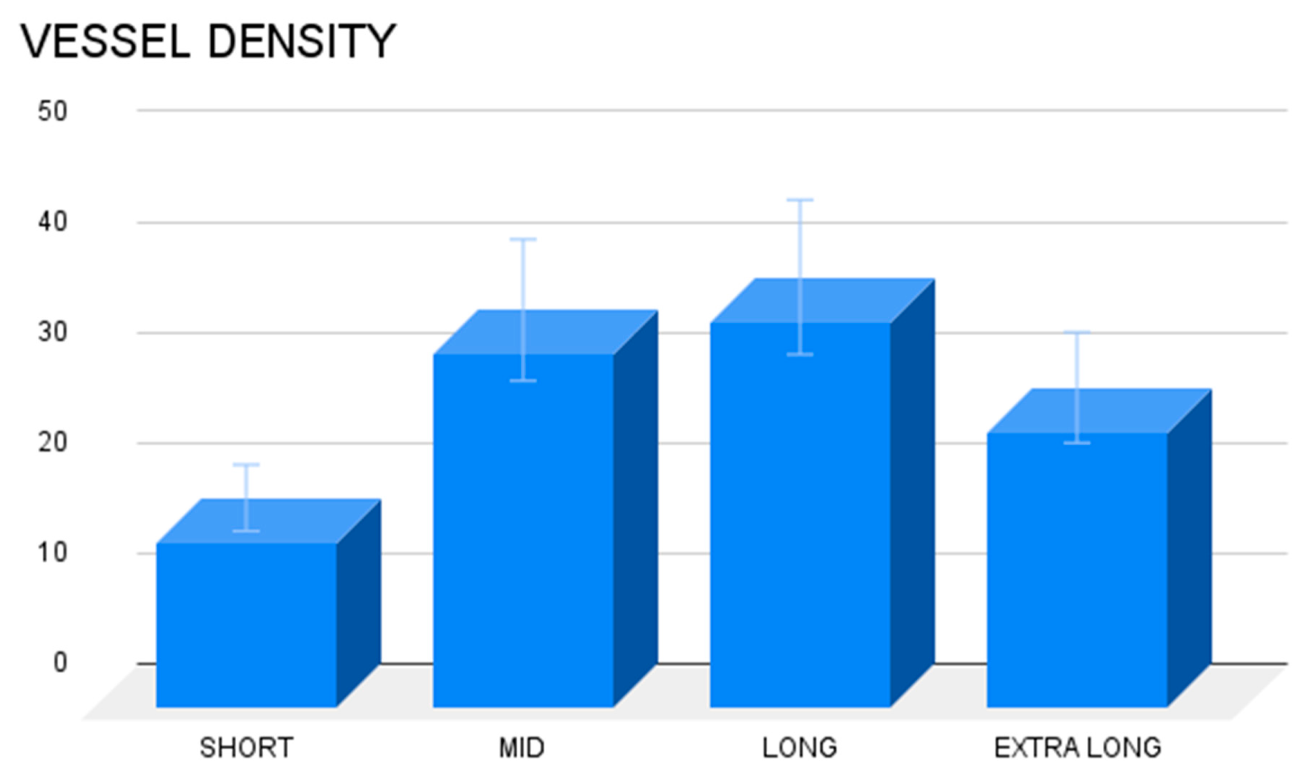
Vascular density of 20 biopsies excised from the 3D dynamic implant at different stages post implantation were compared with one-way Anova and post hoc Tukey test. Results showed statistically significant differences between stages (Table 2) and, in particular, suggested that vascular density in the 3D scaffold of the S&S Hernia System increases over time, up to extra-long term when it was slightly reduced compared to long term stage. Specifically, these outcomes seem to prove that in the long-term vascular density is significantly greater than in the short-term.
4. Discussion
This study aimed to evaluate the integration of newly formed vascular structures within the dynamic, responsive scaffold of the Stenting & Shielding (S&S) Hernia System over defined postoperative periods: short-, mid-, long-, and extra-long-term. The rationale for selecting these specific time frames is rooted in established research, which indicates that by 6-8 months post-implantation, tissue integration with hernia implants generally reaches completion and stabilizes [16,17,18].
The importance of angiogenesis in traditional static hernia meshes has been well-documented. These conventional, flat implants prompt the early onset of vascular proliferation soon after implantation. Initially, this new vascular network supports the incorporation of the mesh through fibrotic tissue growth [17,18,19,20,21,22,23,24]. However, as the process continues, these meshes become encapsulated in a rigid, fibrotic layer, leading to implant shrinkage. [25,26,27,28,29,30,31,32,33,34] During this phase, the vascular network is reduced and primarily functions to sustain the chronic inflammatory response—characterized by macrophages, lymphocytes, and plasma cells—that is typical of these prostheses. [35,36,37] The resulting tissue is often of poor quality, forming dense, stiff scar tissue that can lead to complications such as adhesion formation and nerve entrapment, especially in the inguinal region, potentially causing discomfort and chronic pain.
Understanding the biological processes involved in neo-vessel formation within newly developed tissue is crucial for appreciating the differences observed with the S&S device. Angiogenesis, the process of new blood vessel formation, is essential for providing the necessary metabolic support to developing tissues. [38,39,40,41,42] However, in conventional hernia meshes, the vascular network often fails to fully mature; instead, it primarily supports the maintenance of chronic inflammation rather than nourishing healthy tissue growth. [43] This is not the case with the S&S Hernia System.
In contrast, the S&S device’s dynamic and responsive nature appears to foster a more robust and enhanced biological response. The progressive ingrowth of healthy tissue, supported by continuous and effective angiogenesis, is essential for the development and maturation of complex tissue structures, such as muscle and nerve fibers. The findings of this study suggest that angiogenesis within the 3D scaffold of the S&S device is not only persistent but also evolves in tandem with the development of these highly specialized tissue components.
In the short term, the histological analysis revealed the presence of immature vascular structures, indicative of early-stage angiogenesis. By the mid-term, a more extensive and organized vascular network had formed, with ongoing vascular development occurring within the 3D scaffold. In the long-term phase, the study observed the continued maturation of these vascular elements, which paralleled the development of other tissue components, particularly muscle fibers and nerves. By this stage, the muscular layer of the arterial and venous walls had fully matured, demonstrating the establishment of a competent vascular network capable of sustaining the newly formed, sophisticated tissues within the scaffold.
Finally, in the extra-long period, the vascular structures reached full maturation and appeared significantly more compact than in the previous stage. This likely explains the slight reduction in vascular density observed compared to the long-term period. In this final phase of vascular development, all vessel elements—arteries, veins, and capillaries—exhibited the structural characteristics of fully matured vessels. This well-established vascular network ensures adequate blood supply to the newly formed tissues, particularly muscle and nerve tissues, within the S&S device. All these evidences have been confirmed in detail by the statistical assessment.
Overall, the findings of this study align with previous research that highlights the regenerative capabilities of dynamic scaffolds in hernia repair. [44,45,46,47,48] The S&S Hernia System, with its ability to support ongoing angiogenesis and tissue maturation, demonstrates significant potential as a dynamic regenerative scaffold for the effective treatment of hernia defects.
5. Conclusions
The histological findings from this study suggest that the biological response to synthetic hernia implants is strongly influenced by their structural design. Traditional static and passive flat meshes consistently trigger a foreign body reaction, leading to the formation of stiff, avascular scar tissue. In contrast, when the same synthetic material is configured in a 3D, dynamic structure like the Stenting & Shielding (S&S) Hernia System, the biological response is markedly different. The S&S device, designed to move in harmony with the abdominal wall, fosters a more favorable environment for tissue regeneration. This dynamic interaction appears to promote the ingrowth of muscle fibers, innervated by mature nerve structures, all supported by a well-developed network of blood vessels. Essentially, this device functions as a regenerative scaffold, aligning with the therapeutic goals of addressing the tissue degeneration underlying hernia formation. However, a significant limitation of this study is the lack of a clear explanation for the mechanisms driving the observed neoangiogenesis. Preliminary observations suggest that tissue growth factors may play a role in enhancing the biological response and sustaining the development of new vascular structures. Further research is needed to elucidate these mechanisms. The promising results from this animal model lay a strong basis for future clinical investigations. These studies will be crucial in determining whether the positive biological responses observed here can be replicated in humans. If validated, the S&S Hernia System could represent a significant advancement in hernia repair, potentially simplifying surgical procedures and improving patient outcomes.
Funding
This research received no external funding.
Authors’ contributions
AG Conceptualization A Formal Analysis RV Investigation PR Methodology DBG Software Validation CL Resources CR Data Curation RG Formal Analysis NC Original Draft Preparation Review & editing RG Supervision.
Data Availability Statement
All data supporting the reported results are available upon request from the corresponding author.
Conflicts of Interest
The corresponding author is the developer of the device described in the report. The other authors declare no conflict of interest.
References
- Kingsnorth, A.; LeBlanc, K. Hernias: inguinal and incisional. Lancet 2003, 362, 1561–71. [Google Scholar] [CrossRef]
- Debord, J.R. The historical development of prosthetics in hernia surgery. Surg Clin North Am 1998, 78, 973–10063. [Google Scholar] [CrossRef]
- Amid, P.K. Causes, prevention, and surgical treatment of postherniorrhaphy neuropathic inguinodynia: Triple neurectomy with proximal end implantation. Hernia 2004, 8, 343–349. [Google Scholar] [CrossRef]
- O’Dwyer, P.J.; Kingsnorth, A.N.; Mohillo, R.G.; Small, P.K.; Lammers, B.; Horeysee, G. Randomized clinical trial assessing impact of a lightweight or heavyweight on chronic pain after inguinal hernia repair. Br J Surg 2005, 92, 166–70. [Google Scholar] [CrossRef] [PubMed]
- Rutkow, I.M.; Robbins, A.W. Mesh plug hernia repair: a follow-up report. Surgery 1995, 117, 597–598. [Google Scholar] [CrossRef]
- Aasvang, E.; Kehlet, H. Surgical management of chronic pain after inguinal hernia repair. Br J Surg 2005, 92, 795–801. [Google Scholar] [CrossRef] [PubMed]
- Amato, G.; Marasa, L.; Sciacchitano, T.; Bell, S.G.; Romano, G.; Gioviale, M.C.; Lo Monte, A.I.; Romano, M. Histological findings of the internal inguinal ring in patients having indirect inguinal hernia. Hernia 2009, 13, 259–62. [Google Scholar] [CrossRef] [PubMed]
- Amato, G.; Ober, E.; Romano, G.; Salamone, G.; Agrusa, A.; Gulotta, G.; Bussani, R. Nerve degeneration in inguinal hernia specimens. Hernia 2011, 15, 53–58. [Google Scholar] [CrossRef] [PubMed]
- Amato, G.; Romano, G.; Salamone, G.; Agrusa, A.; Saladino, V.A.; Silvestri, F.; Bussani, R. Damage to the vascular structures in inguinal hernia specimens. Hernia 2012, 16, 63–67. [Google Scholar] [CrossRef] [PubMed]
- Amato, G.; Agrusa, A.; Romano, G.; Salamone, G.; Cocorullo, G.; Mularo, S.A.; Marasa, S.; Gulotta, G. Histological findings in direct inguinal hernia. Hernia 2013, 17, 757–763. [Google Scholar] [CrossRef] [PubMed]
- Amato, G.; Agrusa, A.; Romano, G.; Salamone, G.; Gulotta, G.; Silvestri, F.; Bussani, R. Muscle degeneration in inguinal hernia specimens. Hernia. 2012, 16, 327–31. [Google Scholar] [CrossRef]
- Amato, G.; Agrusa, A.; Rodolico, V.; Puleio, R.; Di Buono, G.; Amodeo, S.; Gulotta, E.; Romano, G. Combined inguinal hernia in the elderly. Portraying the progression of hernia disease. Int J Surg. Suppl 2016, 1, S20–S29. [Google Scholar]
- Amato, G.; Calò, P.; Rodolico, V.; Puleio, R.; Agrusa, A.; Gulotta, L.; Gordini, L.; Romano, G. The Septum Inguinalis: A Clue to Hernia Genesis? J Invest Surg. 2018, 31, 1–9. [Google Scholar] [CrossRef]
- Amato, G.; Agrusa, A.; Rodolico, V.; Caló, P.G.; Puleio, R.; Romano, G. Inguinal Hernia: The Destiny of the Inferior Epigastric Vessels and the Pathogenesis of the Disease. Surg Technol Int. 2020, 36, 105–111. [Google Scholar] [PubMed]
- Kilkenny, C.; Browne, W.J.; Cuthill, I.C.; Emerson, M.; Altman, D.G. Improving Bioscience Research Reporting: The ARRIVE Guidelines for Reporting Animal Research. PLoS Biol 2010, 8, e1000412. [Google Scholar] [CrossRef] [PubMed]
- Weidner, N. Current pathologic methods for measuring intratumoral microvessel density within breast carcinoma and other solid tumors. Breast Cancer Res Treat. 1995, 36, 169–80. [Google Scholar] [CrossRef] [PubMed]
- Amid, P.K.; Shulman, A.G.; Lichtenstein, I.L.; Hakakha, M. Biomaterials for abdominal wall hernia surgery and principles of their applications. Langenbecks Arch Chir 1994, 379, 168–71. [Google Scholar] [CrossRef]
- Klinge, U.; Klosterehalfen, B.; Muller, M.; Ottinger, A.P.; Schumpelick, V. Shrinking of polypropylene mesh in vivo: An experimental study in dogs. Eur J Surg 1998, 164, 96. [Google Scholar] [CrossRef]
- Klosterhalfen, B.; Klinge, U.; Schumpelick, V. Functional and morphological evaluation of different polypropylene-mesh modifications for abdominal wall repair. Biomaterials 1998, 19, 2235–2246. [Google Scholar] [CrossRef]
- EU Hernia Trialist Collaboration Mesh compared with nonmesh methods on open groin hernia repair. Systematic review of randomized controlled trial. Br J Surg 2000, 87, 854–859. [Google Scholar]
- Read, R.C. Recent advances in the repair of groin herniation. Curr Probl Surg 2003, 40, 13–79. [Google Scholar] [CrossRef]
- Amid, P.K. Lichtenstein tension-free hernioplasty: Its inception, evolution, and principles. Hernia 2004, 8, 1–7. [Google Scholar] [CrossRef] [PubMed]
- Amid, P.K. Shrinkage: fake or fact? In: Schumpelick V, Nyhus LM, editors. Meshes: benefits and risks. Springer Berlin, 2004. [Google Scholar]
- Klosterhalfen, B.; Junge, K.; Klinge, U. The lightweight and large porous mesh concept for hernia repair. Expert Rev Med Devices 2005, 2, 103–117. [Google Scholar] [CrossRef] [PubMed]
- Amid, P.K. Causes, prevention, and surgical treatment of postherniorrhaphy neuropathic inguinodynia: Triple neurectomy with proximal end implantation. Hernia 2004, 8, 343–349. [Google Scholar] [CrossRef]
- Bay-Nielsen M, Perkins FM, Kehlet H Danish Hernia Database Pain and functional impairment 1 year after inguinal herniorrhaphy: a nationwide questionnaire study. Am J Surg 2001, 233, 1–7.
- Langbach, O.; Holmedal, S.H.; Grandal, O.I.; Røkke, O. Adhesions to mesh after ventral hernia mesh repair are detected by MRI but are not a cause of long term chronic abdominal pain. Gastroenterol Res Pract. 2016, 2016, 2631598. [Google Scholar] [CrossRef] [PubMed]
- Bay-Nielsen M, Nilsson E, Nordin P, Kehlet H; Swedish Hernia Data Base the Danish Hernia Data Base Chronic pain after open mesh and sutured repair of indirect inguinal hernia in young males. Br J Surg 2004, 91, 1372–1376. [CrossRef]
- Kehlet, H.; Bay-Nielsen, M. Nationwide quality improvement of groin hernia repair from the Danish Hernia Database of 87,840 patients from 1998 to 2005. Hernia 2008, 12, 1–7. [Google Scholar] [CrossRef]
- Nienhuijs S, Staal E, Strobbe L, Rosman C, Groenewoud H, Bleichrodt R Chronic pain after mesh repair of inguinal hernia: a systematic review. Am J Surg 2007, 194, 394–400. [CrossRef] [PubMed]
- Loos MJ, Roumen RM, Scheltinga MR Classifying postherniorrhaphy pain syndromes following elective inguinal hernia repair. World J Surg 2007, 31, 1760–1765. [CrossRef] [PubMed]
- Aasvang EK, Gmaehle E, Hansen JB, et al. Predictive risk factors for persistent postherniotomy pain. Anesthesiology. 2010, 112, 957–969. [Google Scholar] [CrossRef]
- Burgmans JP, Voorbrood CE, Simmermacher RK, et al. Long-term results of a randomized double-blinded prospective trial of a lightweight (Ultrapro) versus a heavyweight mesh (Prolene) in laparoscopic total extraperitoneal inguinal hernia repair (TULP-trial). Ann Surg. 2016, 263, 862–866. [Google Scholar] [CrossRef] [PubMed]
- Andresen K Rosenberg J Management of chronic pain after hernia repair. J Pain Res. 2018, 11, 675–681. [CrossRef] [PubMed]
- Major, M.R.; Wong, V.W.; Nelson, E.R.; Longaker, M.T.; Gurtne, G.C. The foreign body response: at the interface of surgery and bioengineering. Plast Reconstr Surg 2015, 135, 1489–98. [Google Scholar] [CrossRef] [PubMed]
- Klopfleisch, R.; Jung, F. The pathology of the foreign body reaction against biomaterials. J Biomed Mater Res A 2017, 105, 927–940. [Google Scholar] [CrossRef]
- Geelhoed, W.J.; Moroni, L.; Joris, I. Rotmans, J.I. Utilizing the Foreign Body Response to Grow Tissue Engineered Blood Vessels in Vivo J. of Cardiovasc. Trans. Res. 2017, 10, 167–179. [Google Scholar]
- Kumar, V.; Abbas, A.K.; Fausto, N. Blood Vessel. Robbins&Cotran Pathologic Basis of Disease, Philadelphia, Saunders 2005, 513-515.
- Tozzi, P. The physiology of blood flow and artery wall. Springer editor, Sutureless Anastomoses, Darmstadt, Steinkopff, 2007, 12-24.
- Tannock, I.F.; Hayashi, S. The proliferation of capillary endothelial cells. Can Res. 1972, 32, 77–82. [Google Scholar]
- Nakatsu, M.N.; Hughes, C.C. An optimized three-dimensional in vitro model for the analysis of angiogenesis. Methods Enzymol. 2008, 443, 65–82. [Google Scholar]
- Potente, M.; Gerhardt, H.; Carmeliet, P. Basic and therapeutic aspects of angiogenesis. Cell 2011, 146, 873–887. [Google Scholar] [CrossRef] [PubMed]
- Anderson, J.M.; Rodriguez, A.; Chang, D.T. Foreign body reaction to biomaterials. Semin Immunol. 2008, 20, 86–100. [Google Scholar] [CrossRef]
- Amato, G.; Puleio, R.; Romano, G.; Calò, P.G.; Di Buono, G.; Cicero, L.; Cassata, G.; Goetze, T.; Buscemi, S.; Agrusa, A.; et al. Physiologic Cyclical Load on Inguinal Hernia Scaffold ProFlor Turns Biological Response into Tissue Regeneration. Biology 2023, 12, 434. [Google Scholar] [CrossRef] [PubMed]
- Amato, G.; Romano, G.; Puleio, R.; Agrusa, A.; Goetze, T.; Gulotta, E.; Gordini, L.; Erdas, E.; Calò, P. Neomyogenesis in 3D Dynamic Responsive Prosthesis for Inguinal Hernia Repair. Artif Organs. 2018, 42, 1216–1223. [Google Scholar] [CrossRef]
- Amato G, Agrusa A, Puleio R, Calò PG, Goetze T, Romano G Neo-nervegenesis in 3D dynamic responsive implant for inguinal hernia repair. Qualitative study. International Journal of Surgery 2020, 76, 114–119. [Google Scholar]
- Amato, G.; Puleio, R.; Rodolico, V.; Agrusa, A.; Calò, P.G.; Di Buono, G. Romano G, Goetze T. Enhanced angiogenesis in the 3D dynamic responsive implant for inguinal hernia repair ProFlor®. Artif Organs. 2021, 00, 1–10. [Google Scholar]
- Amato G, Agrusa, Puleio R, Micci G, Cassata G, Cicero L, Di Buono G, Calò PG, Galia M, Romano G. A regenerative scaffold for inguinal hernia repair. MR imaging and histological cross evidence. Qualitative study. Int J Surg. 2021, 96, 106170. [Google Scholar]
Figure 1.
A: The Stenting & Shielding (S&S) Hernia System in its pre-delivery configuration, prior to insertion into the abdominal cavity of the experimental pig. B: The S&S device fully deployed, illustrating its final structure. C: The two shields of the S&S Hernia System laparoscopically positioned in front of the abdominal viscera in the lower abdominal wall. D: Ultrasound scan six months post-implantation, showing the 3D scaffold (red circle) filled with newly ingrown tissue (yellow arrows).
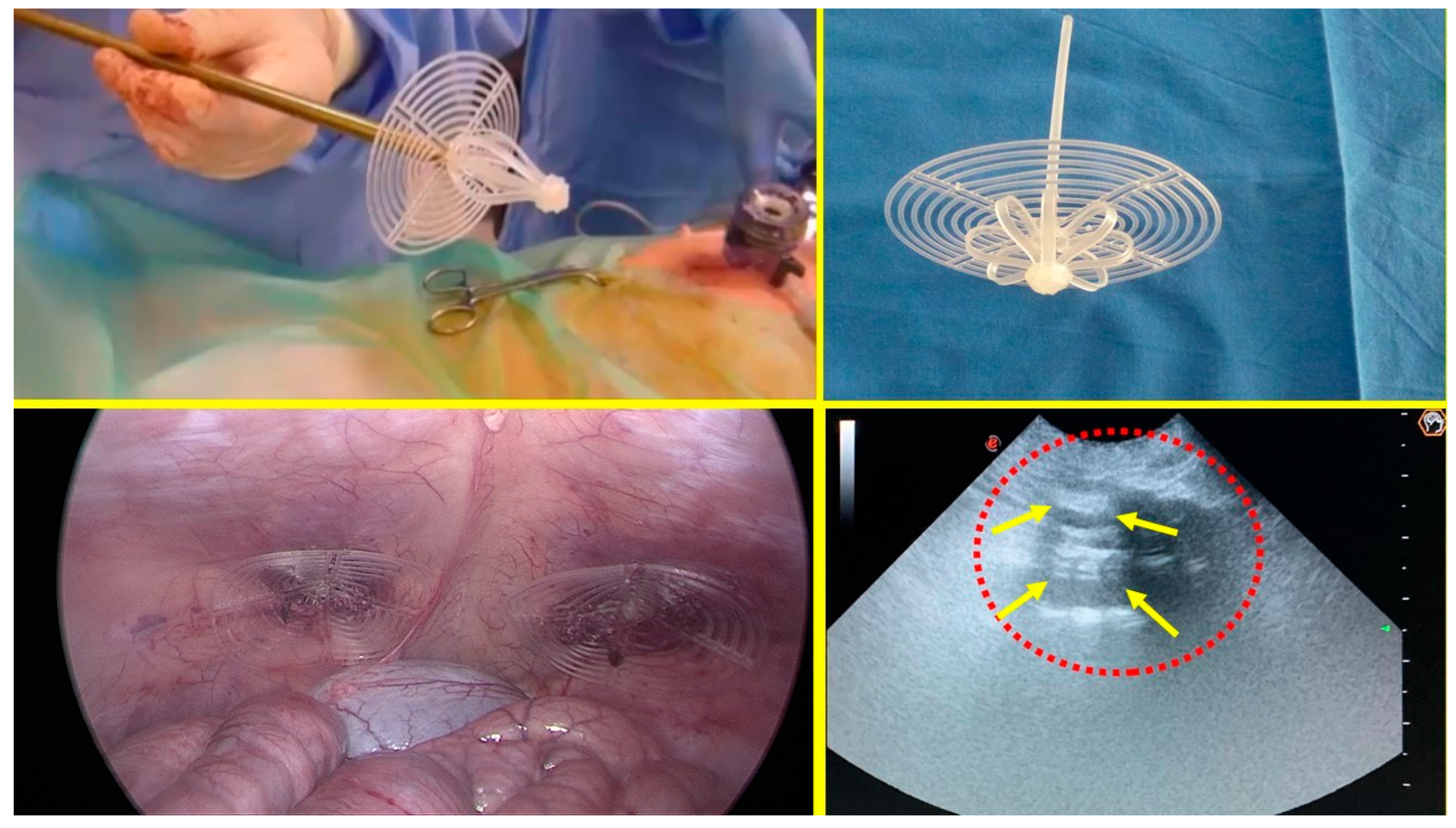
Figure 2.
The S&S Hernia System (red circle) excised three months post-implantation, bisected to reveal viable fleshy tissue (colored in red) that has grown into the 3D scaffold (*) of the device. The shield is indicated by X.
Figure 2.
The S&S Hernia System (red circle) excised three months post-implantation, bisected to reveal viable fleshy tissue (colored in red) that has grown into the 3D scaffold (*) of the device. The shield is indicated by X.
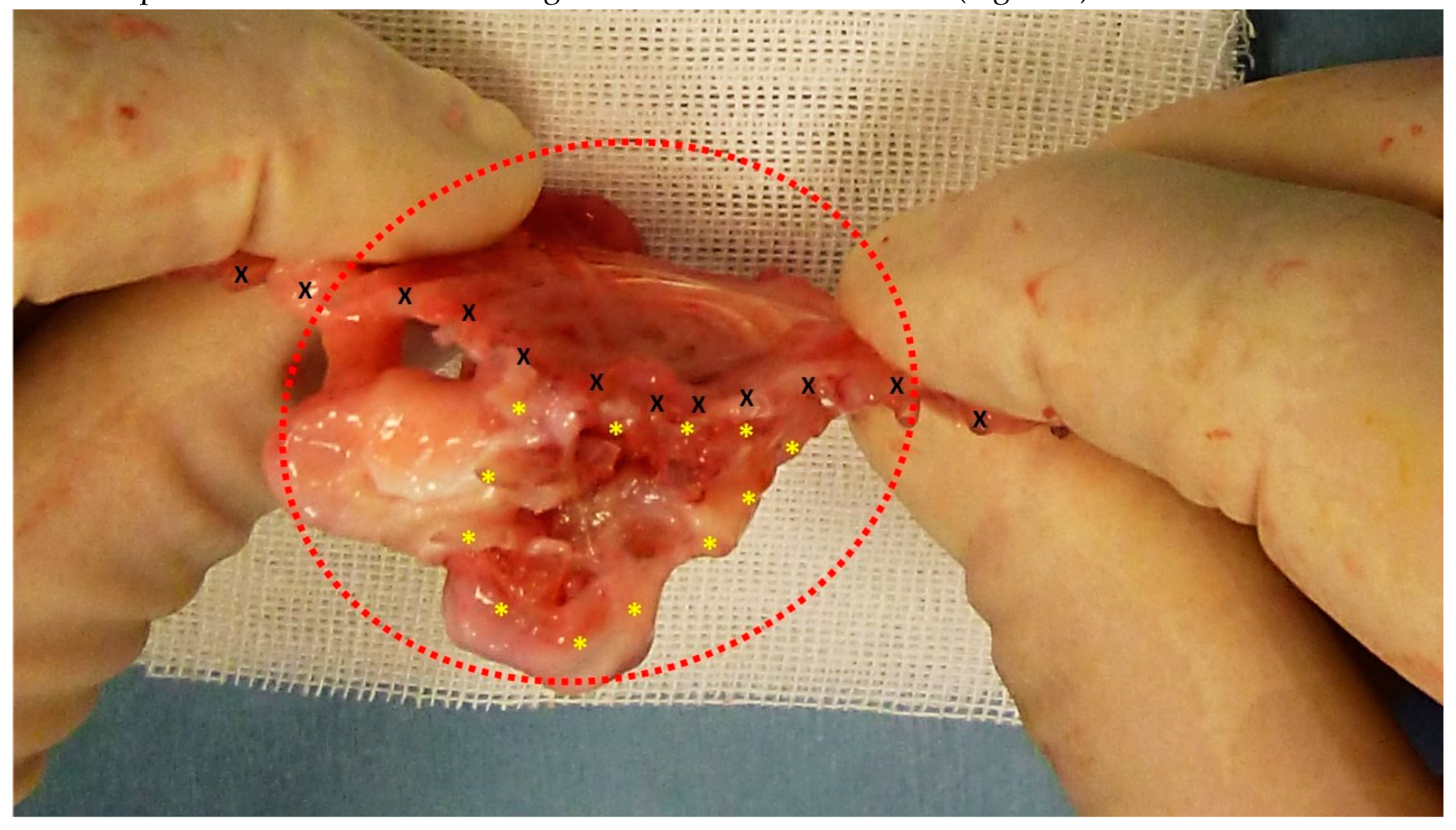
Figure 3.
Biopsy from the 3D scaffold of the S&S device, excised four weeks post-implantation (short-term). Microphotograph reveals numerous newly formed vascular structures in early development (*) adjacent to the S&S device fabric (X) with negligible inflammatory response in well-perfused connective tissue. The inset (right upper corner) provides a magnified view of these developing vascular elements. HE 50X (main image) and HE 100X (inset).
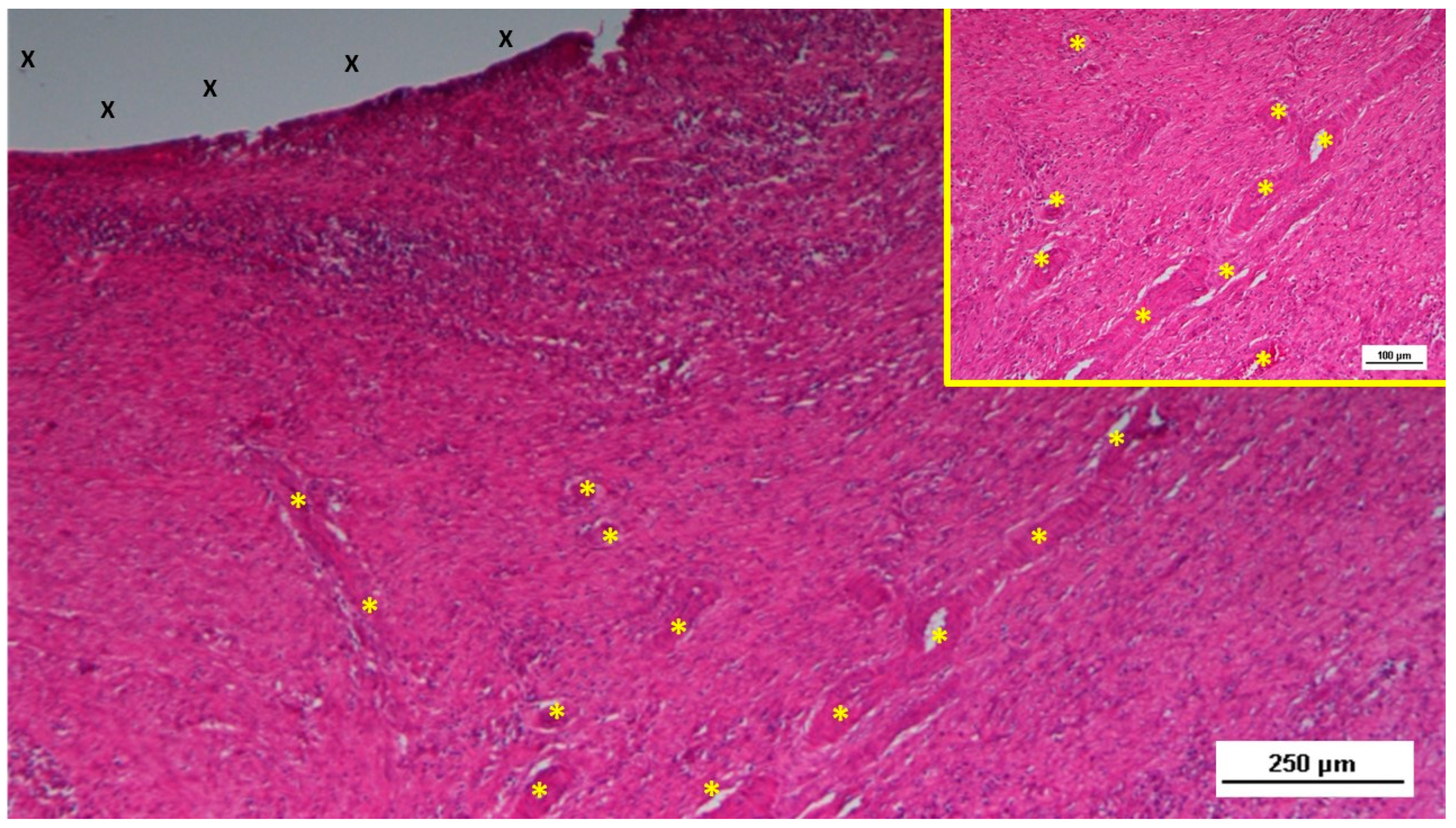
Figure 4.
Biopsy taken five weeks post-implantation from the 3D scaffold of the S&S device. Near the TPE fabric (X), no inflammatory reaction is present, but numerous vascular structures (*)—primarily immature veins—are visible. A yellow circle highlights a cluster of arterial elements in the early-stage of development. The inset (right upper corner) offers a detailed view of the arterial structures with developing muscular layers. HE 25X (main image) and HE 100X (inset).
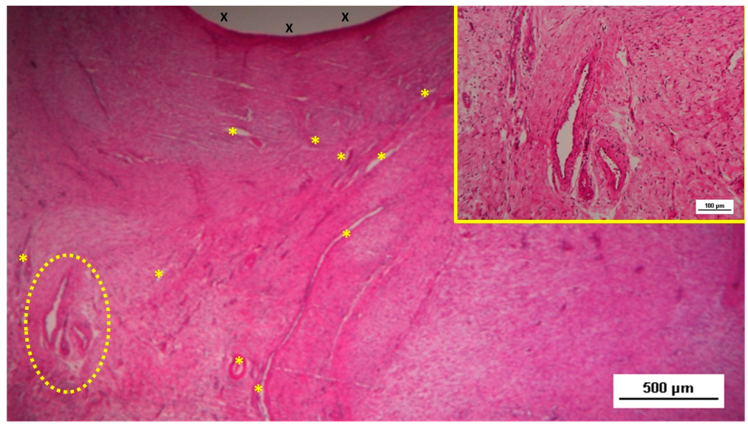
Figure 5.
Biopsy sample from the 3D scaffold of the S&S device, excised four weeks post-implantation. Close to the device fabric (X), a large arterial structure (yellow circle) is seen in its early developmental stage. No inflammatory elements are detectable near the device. HE 25X.
Figure 5.
Biopsy sample from the 3D scaffold of the S&S device, excised four weeks post-implantation. Close to the device fabric (X), a large arterial structure (yellow circle) is seen in its early developmental stage. No inflammatory elements are detectable near the device. HE 25X.
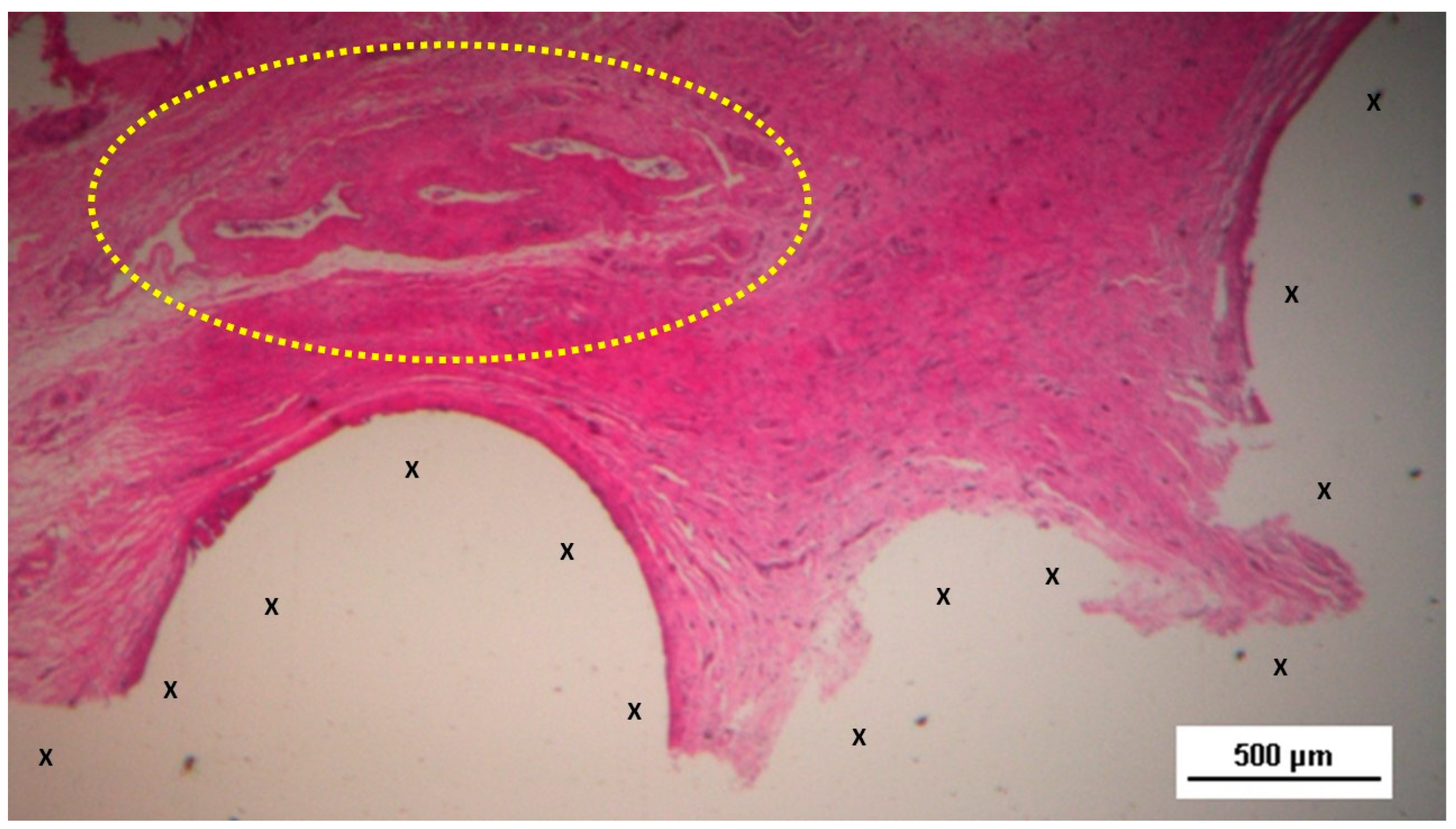
Figure 6.
Biopsy sample from the 3D scaffold of the S&S device, excised five weeks post-implantation. Close to the device fabric (X), several vascular structures (stained in brown) in the initial stage of development are visible in its early developmental stage. No inflammatory elements are detectable near the device. CD31 50X.
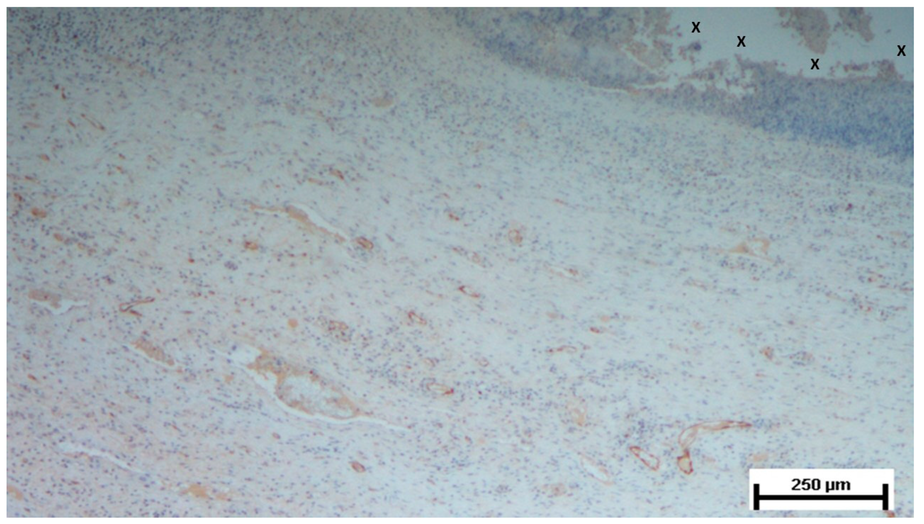
Figure 7.
Biopsy specimen excised three months post-surgery. Microphotograph reveals a large convoluted arterial structure (yellow circle) and several clusters of veins (Y) in advanced stages of development, embedded in well-perfused connective tissue near the S&S scaffold fabric (X), which is free from inflammation. The lower right corner highlights bundles of mature muscle elements (red spots). HE 25X.
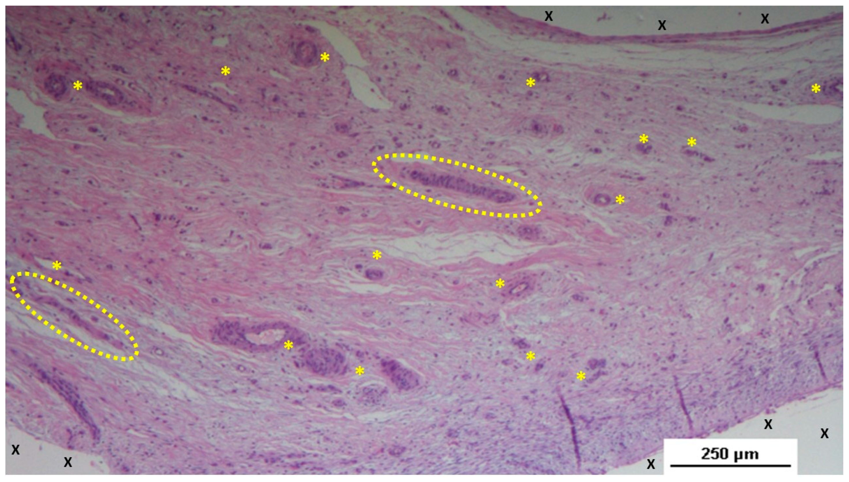
Figure 8.
Biopsy taken four months post-surgery from the 3D scaffold of the S&S Hernia System. Numerous clusters of vascular structures are in advanced stages of development (yellow circle), surrounded by well-hydrated, slack connective tissue containing several muscle bundles (red-stained dotted and striped structures) near the S&S fabric (X), with no signs of inflammation. HE 25X.
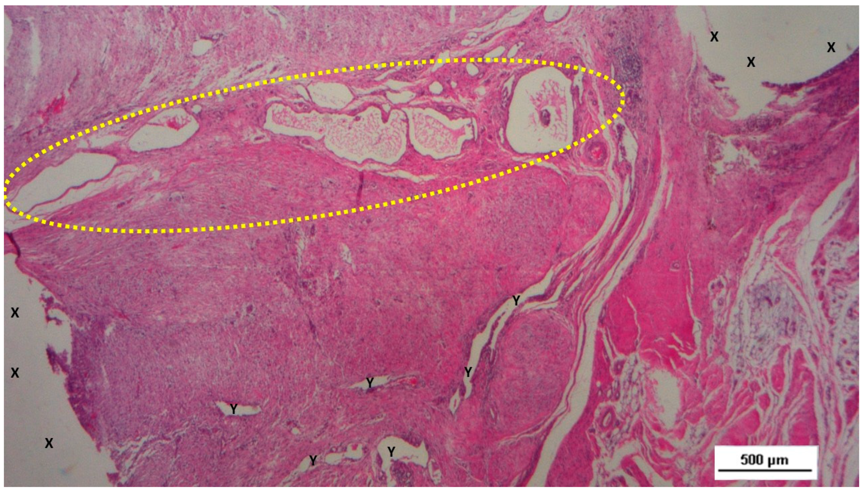
Figure 9.
Biopsy taken four months post-surgery from the 3D scaffold of the S&S Hernia System. Numerous clusters of vascular structures are in advanced stages of development (yellow circle), surrounded by well-hydrated, slack connective tissue containing several muscle bundles (red-stained dotted and striped structures) near the S&S fabric (X), with no signs of inflammation. HE 25X.
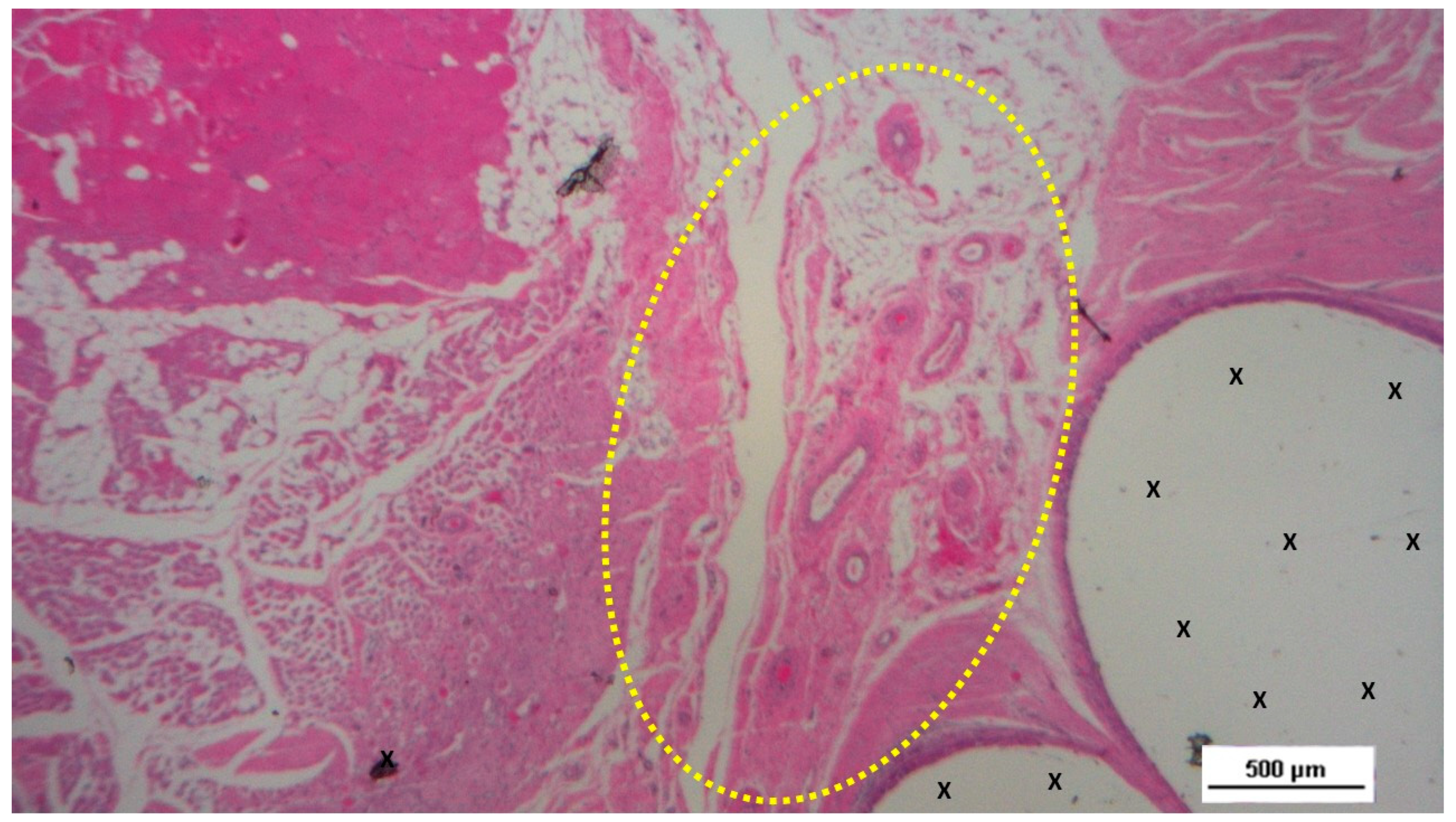
Figure 10.
Biopsy taken four months post-implantation from the 3D scaffold of the S&S Hernia System. Numerous vascular elements in advanced stage of development (stained in brown), close to the S&S fabric (X). CD31 50X.
Figure 10.
Biopsy taken four months post-implantation from the 3D scaffold of the S&S Hernia System. Numerous vascular elements in advanced stage of development (stained in brown), close to the S&S fabric (X). CD31 50X.
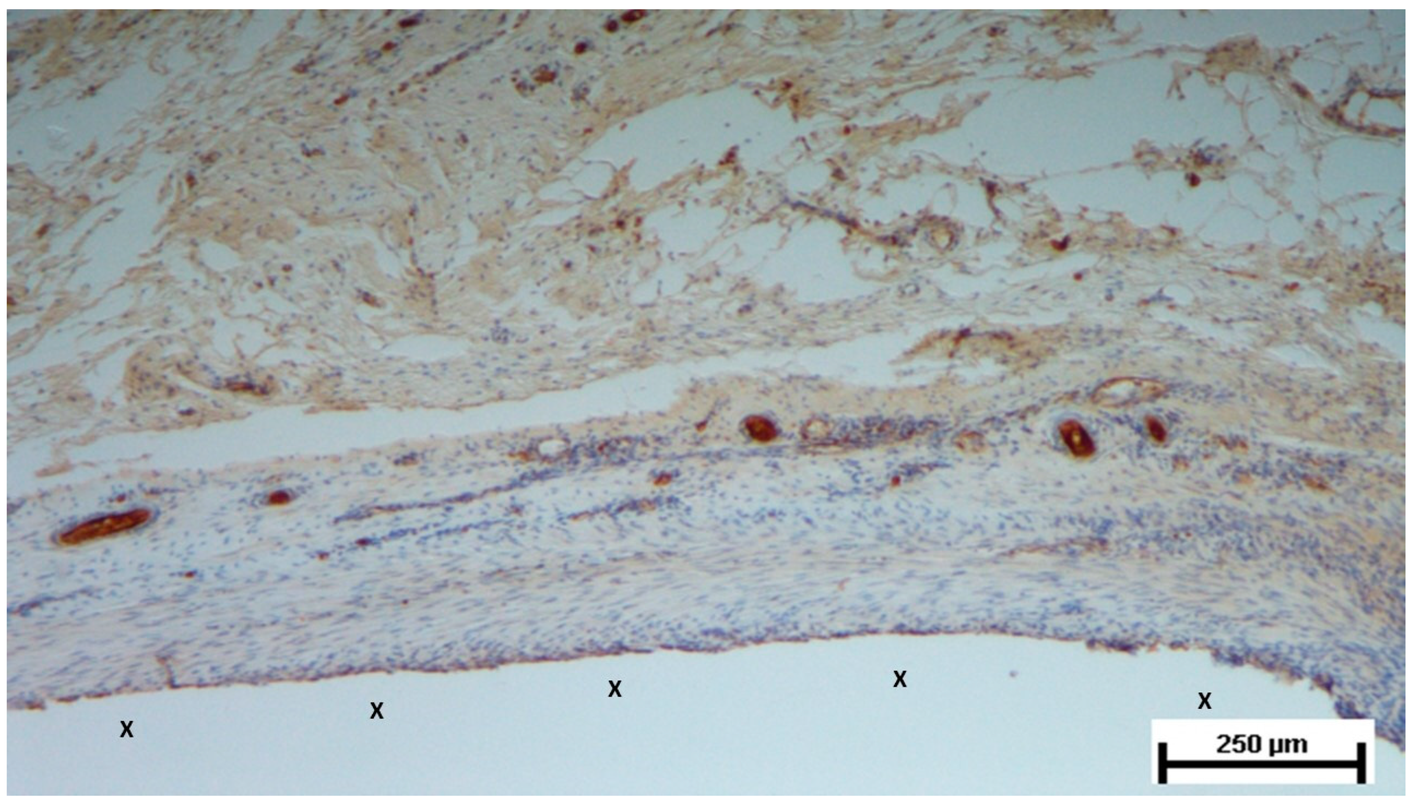
Figure 11.
Low-magnification microphotograph of tissue excised six months post-surgery, showing mature venous structures (white circular spots) and an artery (*) with thick media and adventitia layers, indicating completed structural maturation. The yellow circle encloses a mid-sized nerve. These structures are near the S&S scaffold fabric (X), which lacks inflammatory response. The inset (right upper corner) provides a highly magnified view of the thick arterial structure surrounded by veins (white spots) and the nerve (yellow circle). HE 25X (main image) and 100X (inset).
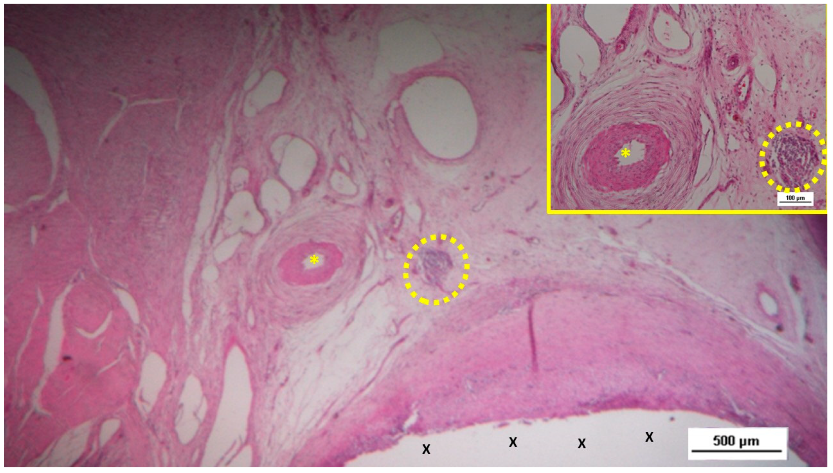
Figure 12.
Biopsy specimen from the 3D scaffold of the S&S device, six months post-surgery. In a matrix of slack, well-perfused connective tissue, several fully developed arterial structures (*) with thickened media are visible. A mature vein (Y) is located near the 3D scaffold fabric (X), which is free from inflammatory infiltration. HE 100X.
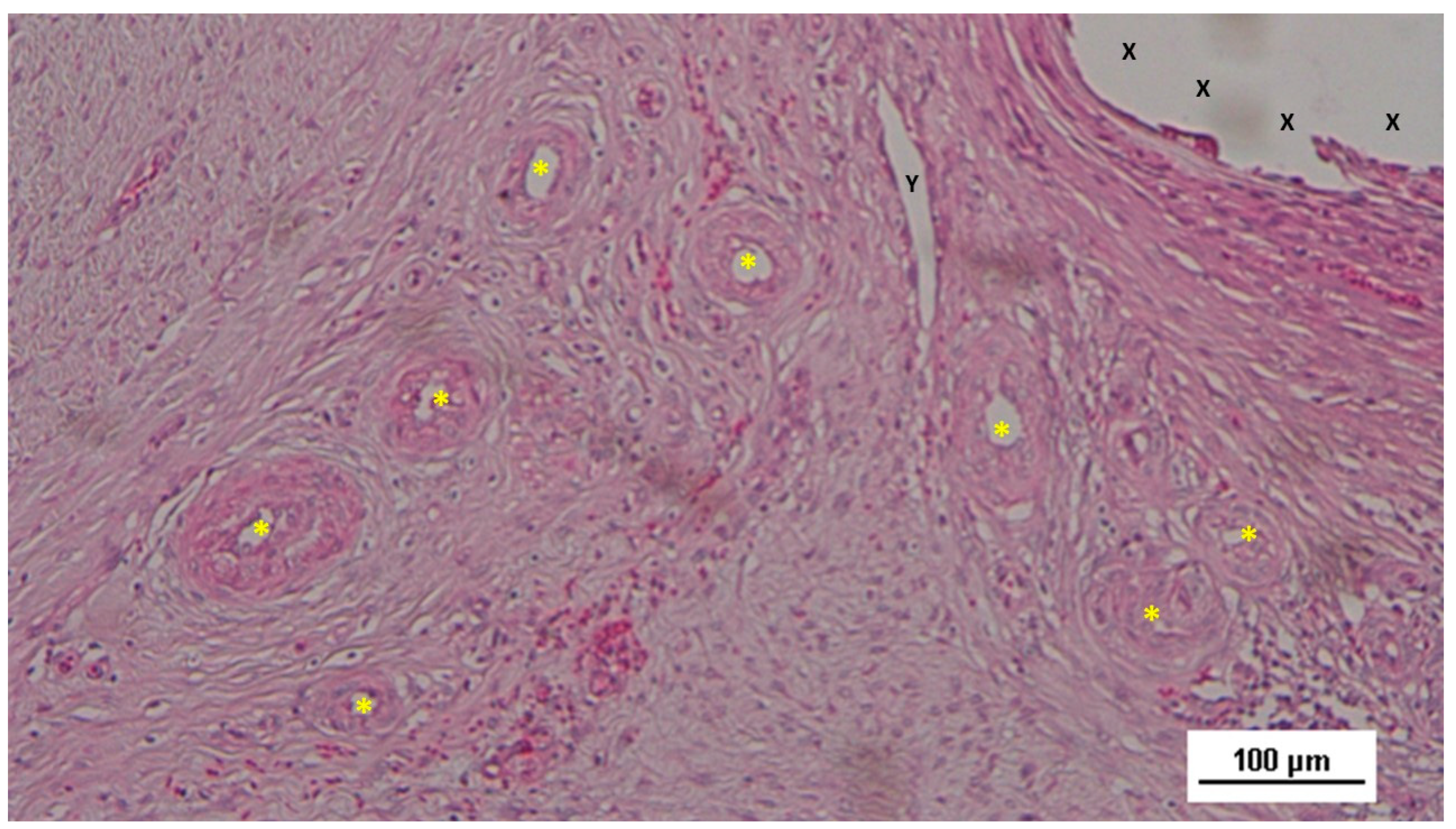
Figure 13.
Biopsy sample excised seven months post-implantation from the 3D scaffold of the S&S device. Adjacent to the S&S scaffold fabric (X), a large, well-developed artery (yellow circle) with a thick muscular layer and healthy endothelium is visible. Some veins (*) and numerous mature muscle bundles (red spots) are also evident. HE 50X.
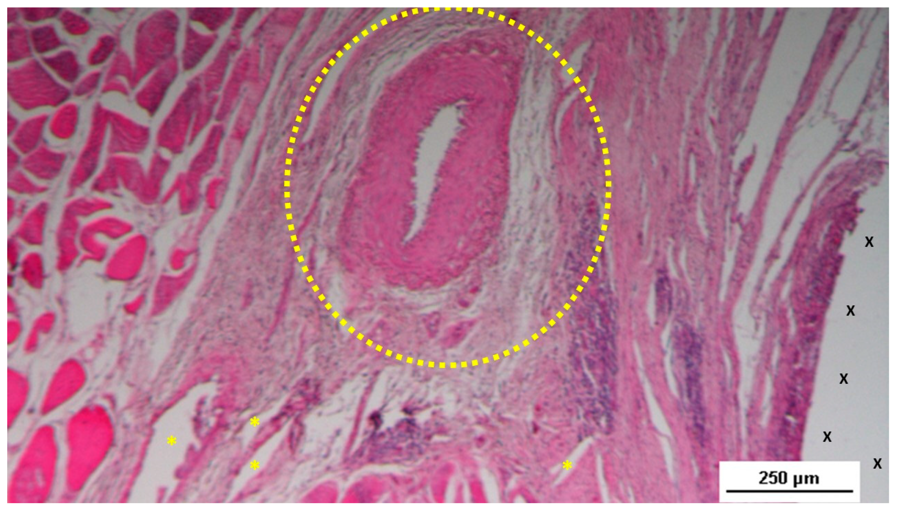
Figure 14.
Biopsy sample excised six months post-implantation from the 3D scaffold of the S&S device. The microphotograph shows multiple arterial structures (targeted elements) and veins (white spots) within a slack connective matrix, situated between two areas of muscle tissue (red-stained). No inflammatory reaction is evident near the S&S device fabric (X). The inset (lower left corner) provides a magnified view of an artery, displaying all three mature layers with a blood-filled lumen (*). HE 25X (main image) and 100X (inset). .
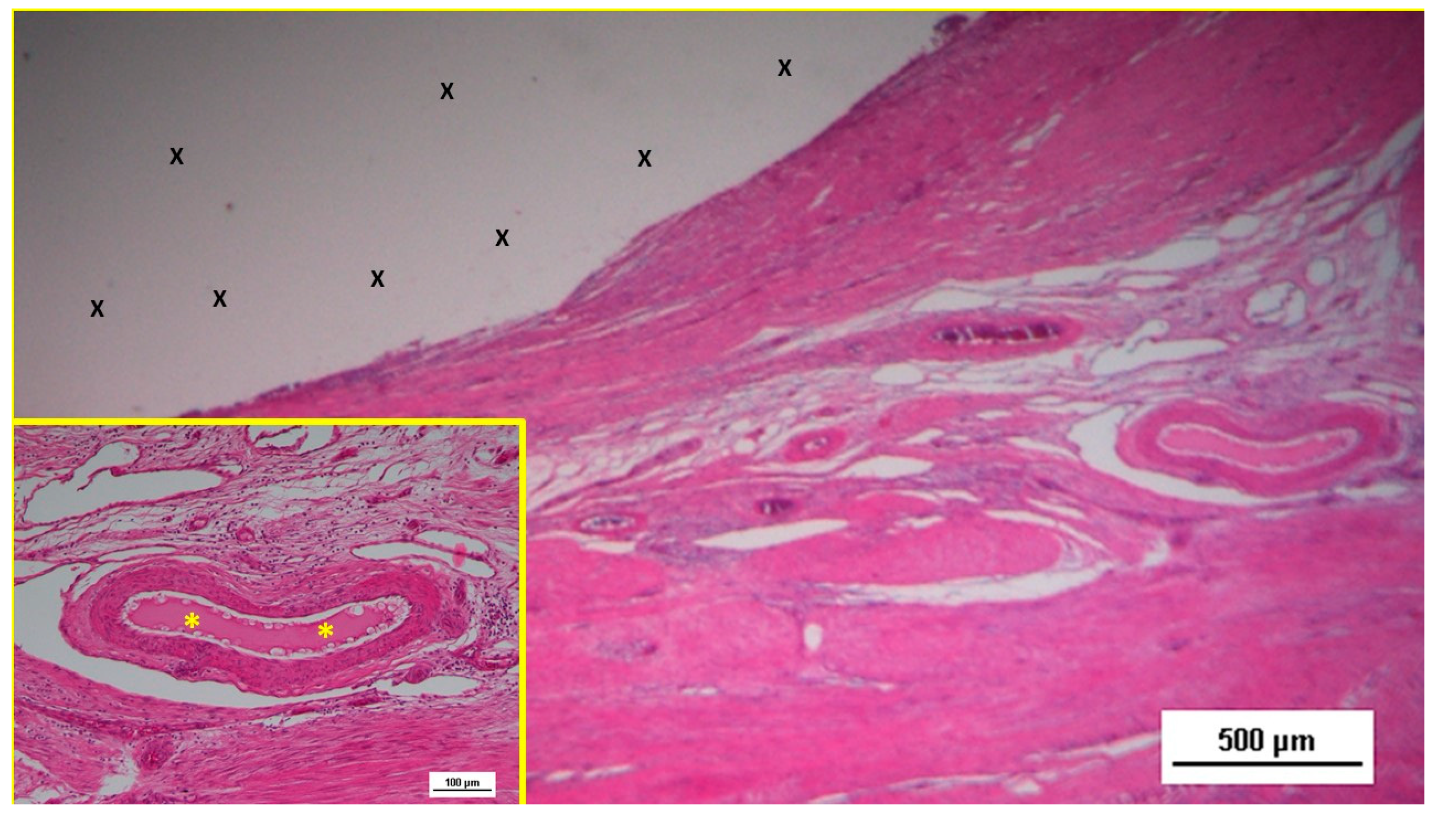
Figure 15.
Biopsy taken six months post-implantation from the 3D scaffold of the S&S Hernia System. Plenty of vascular elements showing fully mature structural arrangement (stained in brown), close to the S&S fabric (X). CD31 25X.
Figure 15.
Biopsy taken six months post-implantation from the 3D scaffold of the S&S Hernia System. Plenty of vascular elements showing fully mature structural arrangement (stained in brown), close to the S&S fabric (X). CD31 25X.
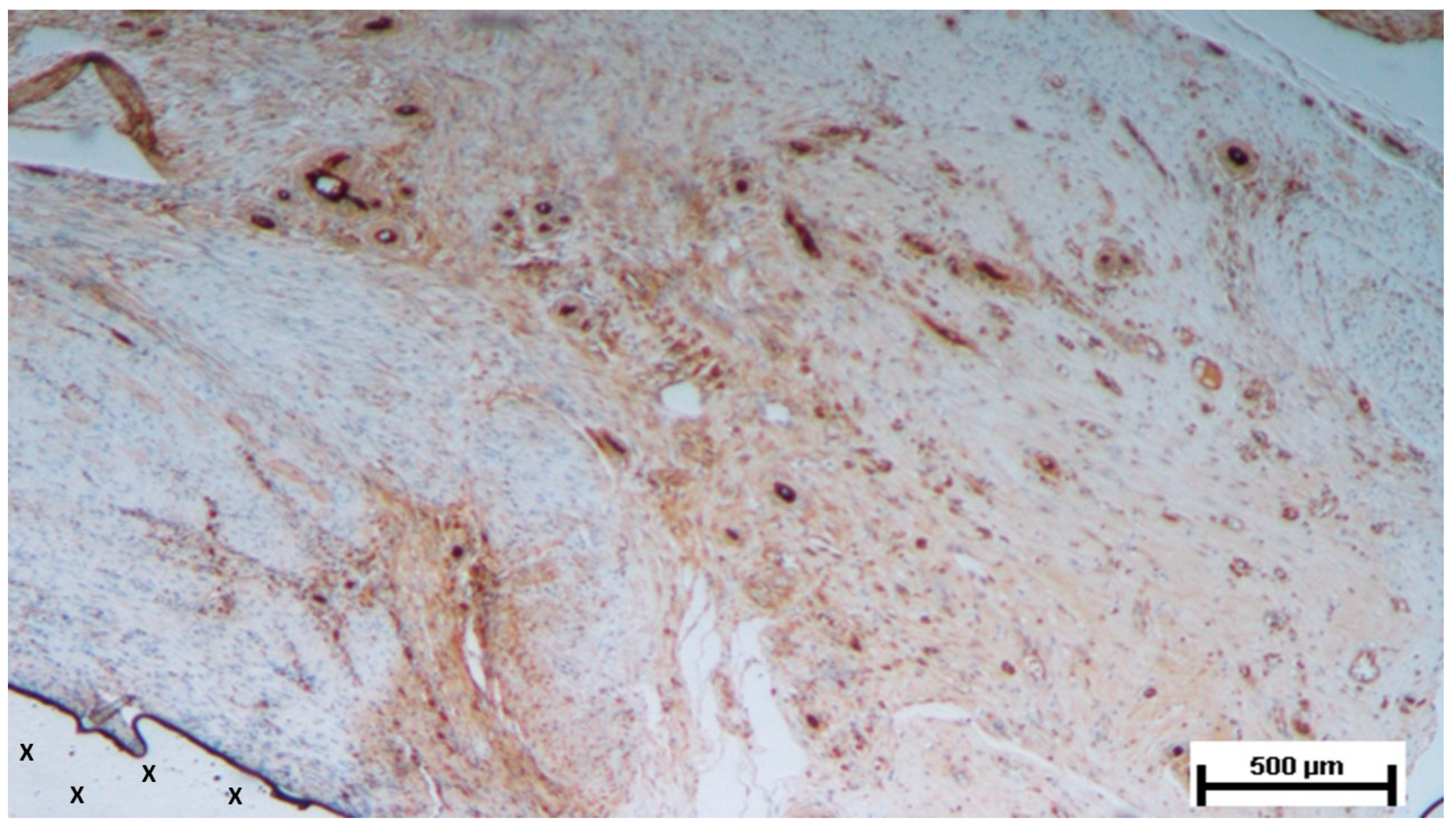
Figure 16.
Biopsy sample excised 18 months post-implantation from the 3D scaffold of the S&S device. The microphotograph highlights a large convoluted artery (*) and venous elements (Y) between the S&S device fabric (X) and a large area of adipocytes (white spots). The artery, showing thick muscular layers, is in a consolidated maturation stage. Strips of mature muscle bundles (red) are visible in the upper right corner and between the S&S structure spires. No inflammatory response is observed on the device fabric. HE 25X.
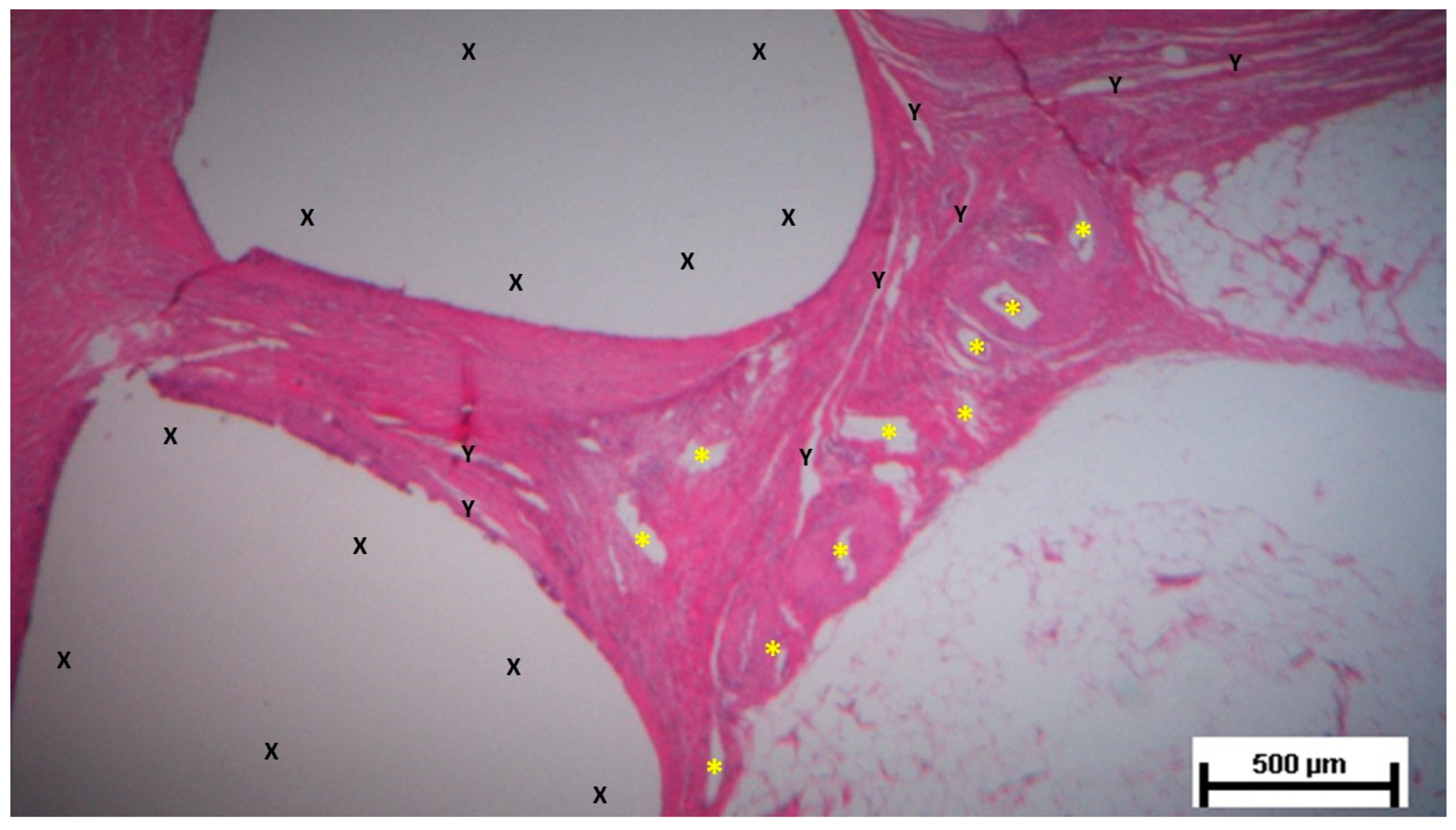
Figure 17.
Biopsy sample excised 18 months post-implantation from the 3D scaffold of the S&S device. The microphotograph shows a large convoluted artery (*) with a thick media layer, in the final stages of maturation, positioned below a large area of adipocytes (white spots) and adjacent to the S&S fabric (X). Mature muscle bundles (red-stained) are visible beneath the artery. No inflammatory infiltrate is present on the device fabric. HE 50X.
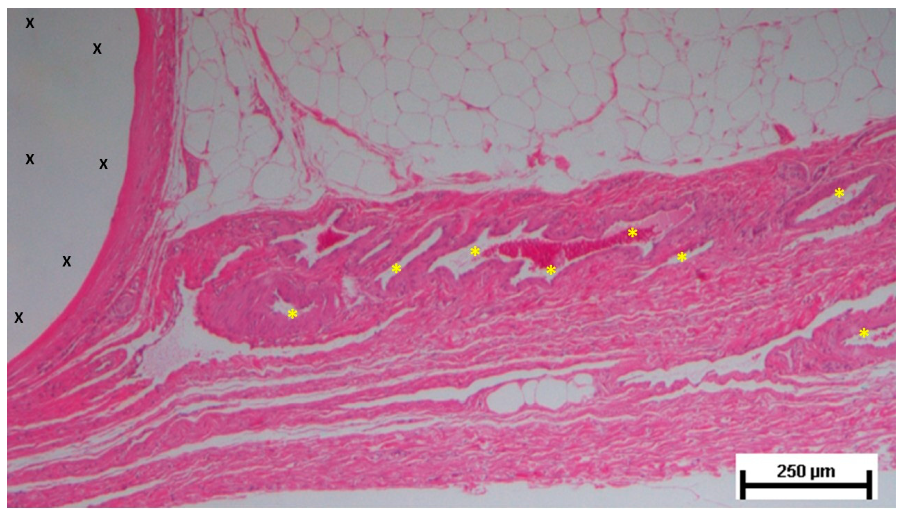
Figure 18.
Tissue specimen taken 18 months post-surgery from the 3D scaffold of the S&S device. The microphotograph highlights several venous elements (Y) and a large convoluted artery (yellow circle) in a consolidated maturation stage. The artery exhibits a thick muscular structure. No inflammatory reaction is detected around the S&S device fabric. HE 100X.
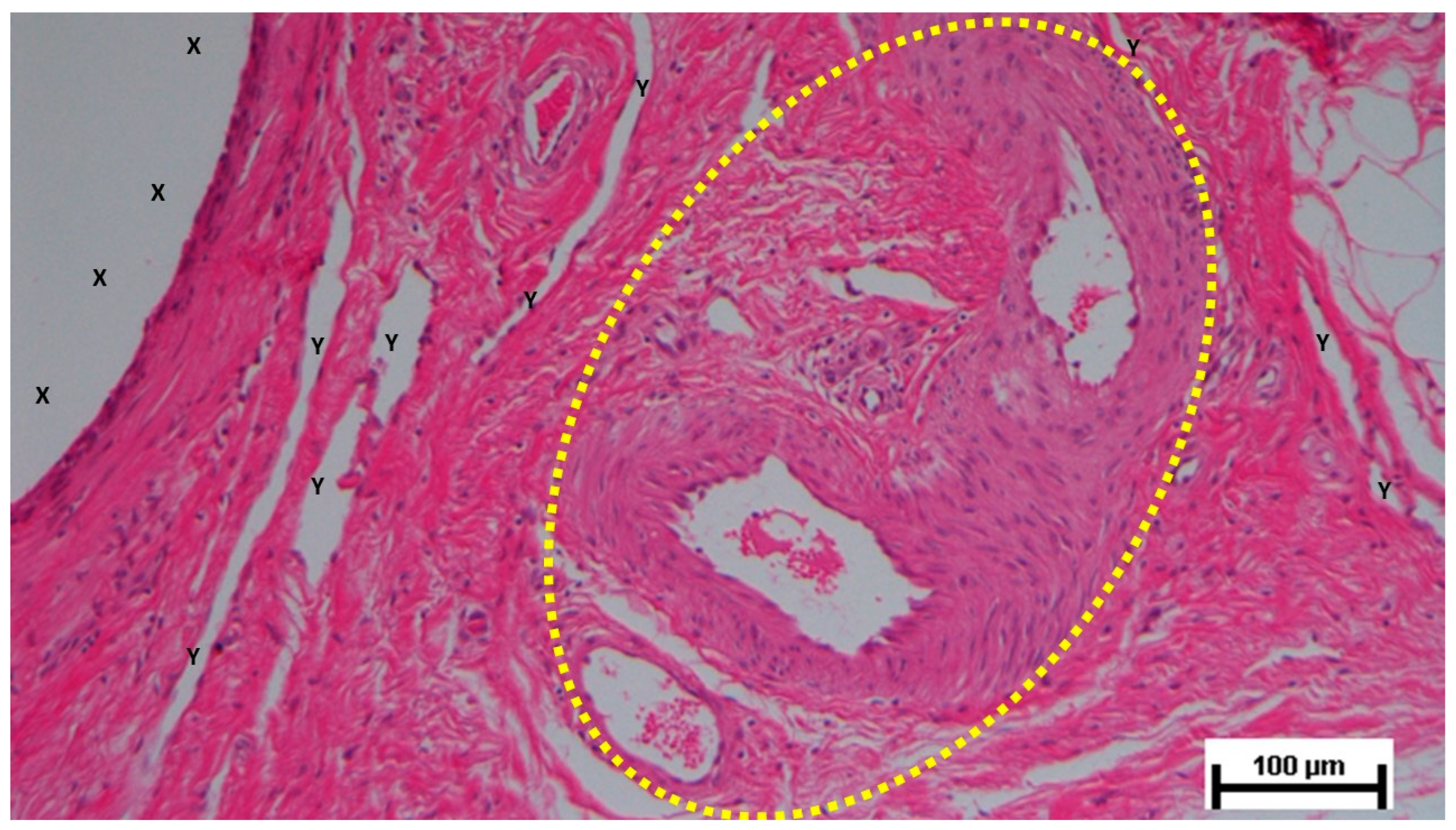
Figure 19.
Histological section of a biopsy sample taken from the 3D scaffold of the S&S device 18 months post-implantation. The image shows two mid-sized mature arteries (*) and veins (Y) embedded in loose, viable connective tissue, located adjacent to the S&S device’s fabric. Notably, there is an absence of inflammatory infiltrate affecting the TPE structure of the device. Mature muscle fibers, organized into bundles (red elongated stripes), are visible along the right margin of the image. HE 100X.
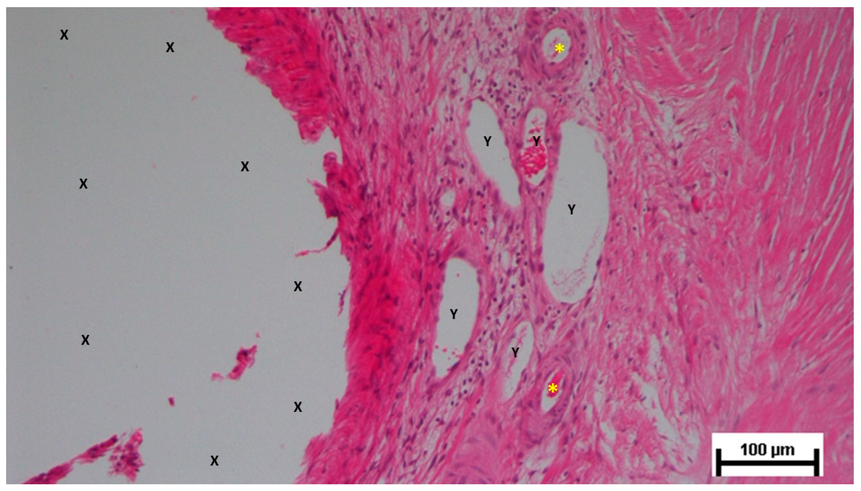
Figure 20.
Biopsy specimen excised from the 3D scaffold of the S&S device 18 months post-implantation. Plenty of vascular elements in consolidated stage of structural maturation (stained in brown), close to the S&S fabric (X). CD31 50X.
Figure 20.
Biopsy specimen excised from the 3D scaffold of the S&S device 18 months post-implantation. Plenty of vascular elements in consolidated stage of structural maturation (stained in brown), close to the S&S fabric (X). CD31 50X.
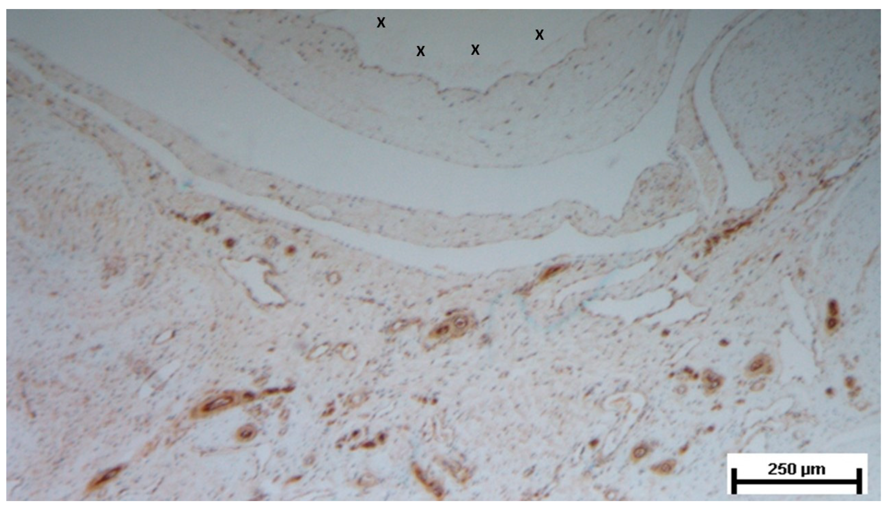

Table 1.
Mechanical properties of the TPE material used for the injection molding of the Stenting & Shielding Hernia System.
Table 1.
Mechanical properties of the TPE material used for the injection molding of the Stenting & Shielding Hernia System.
| TPE mechanical properties | Value | Unit | Test Standard |
| ISO Data | |||
| Tensile Strength | 16 | MPa | ISO 37 |
| Strain at break | 650 | % | ISO 37 |
| Compression set at 70 °C, 24h | 54 | % | ISO 815 |
| Compression set at 100 °C, 24h | 69 | % | ISO 815 |
| Tear strength | 46 | kN/m | ISO 34-1 |
| Shore A hardness | 89 | - | ISO 7619-1 |
| Density | 890 | kg/m³ | ISO 1183 |
Table 2.
Vessel density in different groups: short-, mid-, long- and extra-long-term. In long and mid term group, vessel density was higher than short-term, while in extra-long-term was lower; significant difference (p<0.05) among short- and long-term. * p<0.05
Table 2.
Vessel density in different groups: short-, mid-, long- and extra-long-term. In long and mid term group, vessel density was higher than short-term, while in extra-long-term was lower; significant difference (p<0.05) among short- and long-term. * p<0.05
 |
Disclaimer/Publisher’s Note: The statements, opinions and data contained in all publications are solely those of the individual author(s) and contributor(s) and not of MDPI and/or the editor(s). MDPI and/or the editor(s) disclaim responsibility for any injury to people or property resulting from any ideas, methods, instructions or products referred to in the content. |
© 2024 by the authors. Licensee MDPI, Basel, Switzerland. This article is an open access article distributed under the terms and conditions of the Creative Commons Attribution (CC BY) license (http://creativecommons.org/licenses/by/4.0/).
Copyright: This open access article is published under a Creative Commons CC BY 4.0 license, which permit the free download, distribution, and reuse, provided that the author and preprint are cited in any reuse.


