
Submitted:
02 December 2024
Posted:
03 December 2024
You are already at the latest version
Abstract
Battery electric vehicles (BEVs) are one promising measure to mitigate local greenhouse gas emissions. However, they still lack behind conventional vehicles in terms of maximum driving range. Using the heating, ventilation and air-conditioning (HVAC) system, even further reduces the maximum driving range of the vehicle because the energy for the HVAC system must be taken from the battery. In this paper we experimentally investigate the impact of 1) an air-air heat exchanger and 2) an improved thermal insulation of a truck cabin on the heating performance of the HVAC system. Additionally, we consider the required fresh-air volume flow rate to keep the CO2 level within the truck cabin below the critical value of 1000 ppm. The results show that the two proposed simple measures could increase the energy efficiency of the truck’s HVAC system by 22%. When two persons are present in the truck cabin, a fresh-air volume flow of around 100 m3/h is required to keep the CO2 concentration around 1000 ppm. These results prove that even with simple measures, the energy efficiency of vehicles’ subsystems can be increased. In future, more research will be necessary to further improve energy efficiency also of other vehicular subsystems.
Keywords:
electric vehicle
; air conditioning
; experimental
; heat exchanger
; insulation
; performance
1. Introduction
Due to the climate change, the societal awareness of mitigating air- and noise pollution as well as greenhouse gas emissions is currently very high. Battery electric vehicles (BEVs) represent one of the main drivers in the transportation sector that will help to reach the greenhouse gas targets, set by the European Union in the Green Deal [1]. In the last years, the scientific interest in electrification of vehicles moved from passenger vehicles also towards heavy-duty vehicles, such as trucks and buses [2,3,4,5,6]. However, as the thermal energy for conditioning the cabin in any BEV must be taken from the battery, the maximum driving range decreases at low or high ambient temperatures [4,6,7,8,9,10]. Hence, energy efficiency of the heating, ventilation and air-conditioning (HVAC) system is still one of the main keywords of research in this field.
1.1. Previous Research in the Field
[4] present in their paper an experimental evaluation of the energy consumption of a heating system for a BEV bus at an ambient temperature of 5 °C. In their experiments, they compare the thermal comfort of the passengers when cabin heating is on and off. They conclude that the thermal passenger comfort is only slightly affected when switching the heating system on (compared to when the heating system is switched off) but the maximum driving range of the bus will be drastically reduced by 50% when the heating system is used. For the sake of energy efficiency, [7] propose to directly use the recuperated energy that would be available in deceleration phases of a BEV for heating up the cabin at cold ambient temperatures. With this approach, the authors want to overcome the issue that Lithium-ion batteries can only be charged at low current rates when the battery is still cold. [2] investigate the impact of infrared heating panels to improve the system efficiency of an HVAC system for an electric truck. With their approach they determine an energy saving potential of approximately 30%, compared to a conventional purely convective heating system. [3] compare the energy consumption of an R744-based HVAC system in cooling and heating mode for two different BEV buses. They conclude that the energy consumption of the HVAC system strongly depends on its topology and on the distinct operating point in which the HVAC system is operated. In their paper, [6] conclude that using a heat pump system in a BEV bus can be beneficial in terms of overall energy consumption. Nevertheless, due to the high initial costs of such a system, the direct costs cannot be compensated when assuming an overall life span of twelve years. [10] investigate the effect of recirculation mode on the energy consumption of a plug-in hybrid electric vehicle compared to fresh air mode. They conclude that using recirculation mode can save in average 14% of the energy consumed by the HVAC system.
In [11], the authors compare a hysteresis-based air quality control with a model-based one. The implemented algorithm continuously switches between different ratios of fresh air and recirculated air. However, using a high share of recirculated air decreases the air quality, especially in terms of C concentration. This C-related problem is also analyzed in [11]. The authors investigate a possible air quality control for which they find 1200 ppm as maximum value for the permissible C concentration. [12] study the amount of C that accumulates in vehicles when operating the HVAC system in recirculation mode. They set the C limit for a vehicle with 2 passengers to 1200 ppm. [13] and [14] both develop equations in their papers to calculate the rise in C level in vehicle cabins dependent on the number of passengers, cabin volume and vehicle body leakage. They conclude that the equations can be incorporated into an HVAC control system to determine the required share between recirculation mode and fresh air mode. [13] sets the maximum allowed C level to 700 ppm above the ambient C level, while [14] sets this value to maximum 1000 ppm.
Also, the American Society of Heating, Refrigerating and Air-Conditioning Engineers (ASHRAE) uses 1000 ppm as long-term limit, above which health and cognitive effects may start to occur [15]. These results are in line with those of the previous studies. This supports the necessity to blow in a certain amount of fresh air into the vehicle cabin. On the other hand, when fresh air is blown into cabin, warm air from the cabin will be blown out to the ambient at the same time. Hence, the thermal energy that has been used to heat up the air that enters the cabin will be lost.
1.2. Current Study Novelty and Focus
In this paper we propose two simple but at the same time effective measures to increase the energy efficiency of a heating system for a truck cabin:
- We use an air-air heat exchanger that reuses the thermal energy from the conditioned air that leaves the cabin to pre-heat the fresh air that will be blown into the cabin. This approach allows us to use sufficient fresh air to keep the C concentration within the cabin at a feasible level while, at the same time, keeping the energy consumption low.
- In addition, to mitigate also the thermal losses through the walls, we apply a thermal insulation to the cabin. This measure additionally enhances the thermal performance of the truck cabin and, hence, it further reduces the energy consumption of the HVAC system.
The impact of the proposed measures on the heating performance of the truck cabin will be provided by means of measurement data in a climatic chamber for heating mode at an ambient temperature of -7 °C.
2. Materials and Methods
The literature presented above in the introduction section promotes a maximum C concentration in vehicle cabins varying between 1000 ppm and 1200 ppm. Therefore, we decided to consider for this contribution a maximum C concentration around 1000 ppm. This will ensure that even with slight fluctuations in C concentration, the actual value still remains in a reasonable range.
The authors of [15] derive an equation to calculate the required fresh air flow rate () in [/h], dependent on the number of persons present (),the C generation rate per person (N) in [/h], the maximum allowed C concentration of the indoor space in steady state () in [ppm], and the outdoor C concentration () of the fresh air in [ppm]:
whereas is a conversion factor because the C concentration in Equation 1 is given in ppm.
Based on [16] the C generation rate of one male occupant between 21 and 30 years, with activity levels similar to office work is 0.0064 l/s, which is 0.02304 /h. Using Equation 1 and assuming two persons in the cabin and a slightly elevated ambient C level of 550 ppm, the necessary fresh air intake volume flow to keep the C concentration of the cabin around 1000 ppm is approximately 100 /h:
To verify these numbers from Equation 2, we performed an experiment where we investigated the C concentration that accumulates in a truck cabin with two persons inside, and with controlled inlet fresh air volume flow rate of 100 /h. The results of this investigation will be further discussed in Section 3.1.
A schematic representation of the implemented air-air heat exchanger and the improved insulation is provided in Figure 1. The cabin in this case was in recirculation mode, with no fresh air supplied from the conventional HVAC system, and the cabin temperature, controlled by a proportional–integral–derivative (PID) controller, was set to 23 °C. The heater core was connected to a process thermostat, providing a constant flow of water/glycol coolant at 80 °C and 8 l/min. The air-air heat exchanger was located inside the cabin. Two openings were cut out of the truck cabin chassis, one for fresh air intake and the other one for ventilation exhaust air output. Each of these new openings was equipped with an additional blower, respectively, i.e. an inlet blower and an extraction blower.
These blowers enabled us to control the volume flow of fresh air entering and the volume flow leaving the cabin through the air-air heat exchanger. Additionally, it allows for setting the pressure level within the cabin. If the cabin pressure is lower than the ambient pressure, then outside air will be sucked through leaks in the chassis into the cabin. This drastically increases the thermal losses and, hence, decreases the efficiency of the HVAC system. In contrast, if the pressure within the cabin is higher than the ambient pressure, already conditioned air will leave the cabin through leaks in the chassis. This also results in a less efficient performance of the HVAC system, even if this is not that significant like in the first case. To conclude this topic, the best HVAC system efficiency will be achieved when the cabin pressure is equal to the ambient pressure as this will reduce the thermal losses through leakages.
As can be derived from Equation 1, if two persons are present in the vehicle, the volume flow of fresh air needs to be set to 100 /h. The air volume flow at the additional inlet was measured, and the blower settings were recorded for further control adjustments and for evaluation purposes.
As can be seen in the schematic Figure 1, also the thermal insulation has been improved. We attached insulation material at all possible interior surfaces of the truck cabin, i.e., at the roof, the back wall, the floor, and also the side doors.
To investigate the impact of the proposed measures, the thermal performance of the truck cabin was tested in a climatic chamber at an ambient temperature of -7 °C. The cabin target temperature was set to 23 °C and the PID controller, shown in Figure 1, controlled the cabin blower with the mean cabin temperature as feedback. The mean cabin temperature was calculated based on eight temperature sensors, which were installed in the cabin at the following locations: driver head, -chest and -feet, co-driver head, -chest and -feet, cabin center, and bottom center. Then, the performance of the original cabin was compared to the improved cabin in 5 different test cases, which are provided in Table 1, where Case1 is the baseline truck cabin as a reference, and Case5 is the improved cabin including all proposed measures.
In these 5 test cases we compare the total power consumption of the HVAC system:
with as the required heating power to heat up the coolant to the target temperature of 80 °C, as the measured power consumption of the main blower, and as the sum of the measured power consumption of the additional inlet- and extraction blowers.
As we use a process thermostat to heat up the coolant to the desired temperature, the required heating power in [W] can be calculated from Equation 4 by measuring the coolant temperature before the heater core () in [°C], the coolant temperature after the heater core () in [°C], and the coolant volume flow rate () in [/s]. For solving Equation 4, we further need the fluid properties of a water-glycol 1:1 mixture, compare also [17], which are the density ( = 1042 kg/) and the specific heat capacity of the coolant ( = 3657 J/kg·K).
The power consumption and the measured temperatures presented in Section 3 do not include the transient heat-up phase of the truck cabin. To allow for a fair evaluation, these values are average values that have been recorded once the cabin temperature has reached steady state. Then, an average value was calculated for each of the quantities over a measurement time of at least 1500 s in steady state.
3. Results
The measurement results are provided in this section. Section 3.1 presents the measurement results regarding the C concentration, while Section 3.2 presents the results of the measured power consumption of the HVAC system in the five test cases.
3.1. C Concentration
First, applying Equation 2 for two persons in the truck cabin showed that it requires approximately 100 /h fresh air to keep the C concentration around 1000 ppm. In the next step, to prove this result, we performed an experiment with two persons in the cabin and an incoming volume flow rate of fresh air of 100 /h while we measured the trend of the C concentration. The results are provided in Figure 2. They prove that with a volume flow of 100 /h of fresh air, the C concentration within the truck cabin remains around the targeted value of 1000 ppm when two persons are present. In the steady-state phase, after 400 s, the measured C levels fluctuate by up to ± 80 ppm around the mean value of 1004 ppm.
3.2. Power Demand for Heating
Figure 3 shows the measurement results with regard to the total power consumption of the HVAC system at steady state of the cabin temperature for the five different test cases from Table 1. Case1 is the baseline measurement in fresh air mode. This scenario, with 3311 W power consumption, serves as a reference for analyzing the impact of the measures from the other cases on the total power consumption of the HVAC system. Case2 shows the impact of recirculation mode. Here, the total power consumption is 2470 W. When comparing this value to the results of Case1, this means a reduced power consumption of 25%. Case3 features an insulated truck cabin in fresh air mode. Here, a power consumption of 2886 W was measured, which means an improved efficiency of 13% compared to Case1. The least power consumption could be achieved by the insulated truck cabin that is operated in pure recirculation mode, i.e. Case4. In this scenario the results show a power consumption of only 2263 W, which is 32% lower than the one measured in Case1. The total power consumption of the HVAC system when applying both proposed measures, i.e. the improved thermal insulation and the air-air heat exchanger, is represented by Case5. With a power consumption of 2571 W, which means a reduction of the power consumption by 22% compared to Case1, this scenario has achieved the best efficiency of all realistic cases, considering also a specific amount of fresh air to keep the C level inside the truck cabin at a feasible level. Further discussion of the measurement results are provided in Section 4.
4. Discussion
The proposed concept with the air-air heat exchanger and the controlled volume flow rate of fresh air of 100 /h, calculated by Equation 2, has been successfully verified with the presented measurement data from Figure 2. The mean value of the measured C levels has been 1004 ppm. However, the C sensor for measuring the presented C concentration in the truck cabin was placed between the driver and the co-driver, approximately 30 cm above their heads. Therefore, dependent on the alignment of the passengers’ heads, the measured C levels fluctuate by up to ± 80 ppm around the mean value.
Regarding the power consumption of the different scenarios, provided in Figure 3, Case1 is the worst case. As this is the power consumption of the original vehicle, the presented value serves as a baseline to quantify the efficiency gains of the other scenarios. Case2 shows the impact of only recirculation mode. Comparing the measured power consumption to the one from Case1, a reduced power consumption of 25% could be achieved. However, this is not a realistic scenario because, as already stated in the previous part of the paper, operating the HVAC system in pure recirculation mode will result in issues regarding the maximum permissible C concentration in the truck cabin. Comparing Case3 with the baseline Case1 shows the impact of an improved insulation. This simple measure could reduce the power consumption of the HVAC system by 13%. Case4 is the best scenario, although it is not realistic because pure recirculation mode is used again. However, this scenario represents the maximum achievable efficiency, to quantify how good the air-air heat exchanger and the improved insulation performance is in terms of the globally achievable efficiency. The measures of Case4 achieved a reduction of the energy consumption of 32%, compared to the baseline Case1. Case5 is the best case of the realistic scenarios. Here, sufficient fresh air is used to keep the C level at a feasible level. When comparing the results to Case1, the power consumption could be reduced by 22%. The proposed measures have achieved an improved energy efficiency of the HVAC system and are easy to implement for original equipment manufacturers (OEMs). Hence, they can contribute to making electric vehicles more attractive to people.
5. Conclusions
This paper presented experimental results investigating the impact of an air-air heat exchanger and an improved insulation on the performance of an HVAC system for a truck cabin. The proposed measures take also into account the C levels that arise in vehicle cabins when they are operated in recirculation mode. The power consumption of the HVAC system in heating mode for different vehicle setups has been measured. Measurement data have been provided which prove that the proposed concept does not exceed critical C levels. The proposed measures are easy to implement for OEMs and, as a combined bundle of measures, they can reduce the power consumption of the HVAC system by 22%, compared to the original vehicle setup.
The results show that even simple measures can significantly increase the system efficiency of HVAC systems. This is especially relevant for BEVs, as the energy for the HVAC system must be taken from the battery, which, in turn, reduces the maximum driving range of the vehicle. In future, further research needs to be conducted to improve the efficiency of vehicular subsystems, such as the HVAC system, to make BEVs step-by-step more attractive to people.
Author Contributions
Conceptualization, D.D. and M.K.; methodology, D.D. and M.K.; validation, D.D., M.K. and I.G.; formal analysis, M.K. and I.G.; investigation, D.D., M.K. and I.G.; writing—original draft preparation, D.D. and M.K.; writing—review and editing, I.G.; visualization, D.D., M.K. and I.G.; supervision, D.S.; project administration, D.S.; funding acquisition, D.S. All authors have read and agreed to the published version of the manuscript.
Funding
This research was funded by European Union’s Horizon research and innovation program under grant number 101096028. The content of this publication is the sole responsibility of the consortium partners listed herein and does not necessarily represent the view of the European Commission or its services.
Conflicts of Interest
The authors declare no conflicts of interest. The funders had no role in the design of the study; in the collection, analyses, or interpretation of data; in the writing of the manuscript; or in the decision to publish the results.
Abbreviations
The following abbreviations are used in this manuscript:
| ASHRAE | American society of heating, refrigerating and air-conditioning engineers |
| BEV | Battery electric vehicle |
| C | Carbon dioxide |
| HVAC | Heating, ventilation and air-conditioning |
| OEM | Original equipment manufacturer |
| PID | Proportional–integral–derivative controller |
References
- European Union. The European Green Deal. Available online: https://commission.europa.eu/strategy-and-policy/priorities-2019-2024/european-green-deal_en (accessed on 05.11.2024).
- Gellai, I.; Popovac, M.; Kardos, M.; Simic, D. Numerical analysis of the energy efficiency measures for improving the truck cabin thermal performance. Engineering Modelling, Analysis and Simulation 2024, 2, 1–8. [CrossRef]
- Heß, L.; Dimova, D.; Piechalski, J.W.; Rusche, S.; Best, P.; Sonnekalb, M. Analysis of the Specific Energy Consumption of Battery-Driven Electrical Buses for Heating and Cooling in Dependence on the Technical Equipment and Operating Conditions. World Electric Vehicle Journal 2023, 14. [CrossRef]
- Cigarini, F.; Fay, T.A.; Artemenko, N.; Göhlich, D. Modeling and experimental investigation of thermal comfort and energy consumption in a battery electric bus. World Electric Vehicle Journal 2021, 12, 1–22. [CrossRef]
- Moll, C.; Plötz, P.; Hadwich, K.; Wietschel, M. Are battery-electric trucks for 24-hour delivery the future of city logistics?-A german case study. World Electric Vehicle Journal 2020, 11. [CrossRef]
- Göhlich, D.; Ly, T.A.; Kunith, A.; Jefferies, D. Economic assessment of different air-conditioning and heating systems for electric city buses based on comprehensive energetic simulations. World Electric Vehicle Journal 2015, 7, 398–406. [CrossRef]
- Steinstraeter, M.; Heinrich, T.; Lienkamp, M. Effect of low temperature on electric vehicle range. World Electric Vehicle Journal 2021, 12. [CrossRef]
- Dvorak, D.; Basciotti, D.; Gellai, I. Demand-based control design for efficient heat pump operation of electric vehicles. Energies 2020, 13. [CrossRef]
- Lajunen, A.; Yang, Y.; Emadi, A. Review of Cabin Thermal Management for Electrified Passenger Vehicles. IEEE Transactions on Vehicular Technology 2020, 69, 6025–6040. [CrossRef]
- Li, C.; Brewer, E.; Pham, L.; Jung, H. Reducing mobile air conditioner (MAC) power consumption using active cabin-air-recirculation in a plug-in hybrid electric vehicle (PHEV). World Electric Vehicle Journal 2018, 9, 1–15. [CrossRef]
- Schutzeich, P.; Pischinger, S.; Hemkemeyer, D.; Franke, K.; Hamelbeck, P. A Predictive Cabin Conditioning Strategy for Battery Electric Vehicles. World Electric Vehicle Journal 2024, 15. [CrossRef]
- Goh, C.C.; Kamarudin, L.M.; Shukri, S.; Abdullah, N.S.; Zakaria, A. Monitoring of carbon dioxide (CO2) accumulation in vehicle cabin. 2016 3rd International Conference on Electronic Design, ICED 2016 2016, pp. 427–432. [CrossRef]
- Jung, H. Modeling CO2 concentrations in vehicle cabin. SAE Technical Papers 2013, 2, 1–6. [CrossRef]
- Wei, D.; Nielsen, F.; Karlsson, H.; Ekberg, L.; Dalenbäck, J.O. Vehicle cabin air quality: influence of air recirculation on energy use, particles, and CO2. Environmental Science and Pollution Research 2023, 30, 43387–43402. [CrossRef]
- Persily, A.; Bahnfleth, W.P.; Kipen, H.; Lau, J.; Mandin, C.; Sekhar, C.; Wargocki, P.; Weekes, L.C.N. ASHRAE Position Document on Indoor Carbon Dioxide 2022.
- Persily, A.; de Jonge, L. Carbon dioxide generation rates for building occupants. Indoor Air 2017, 27, 868–879. [CrossRef]
- The Engineering ToolBox. Ethylene Glycol Heat-Transfer Fluid Properties. Available online: https://www.engineeringtoolbox.com/ethylene-glycol-d_146.html (accessed on 20.11.2024).
Figure 1.
Schematics of the implemented air-air heat exchanger and the improved thermal cabin insulation.
Figure 1.
Schematics of the implemented air-air heat exchanger and the improved thermal cabin insulation.
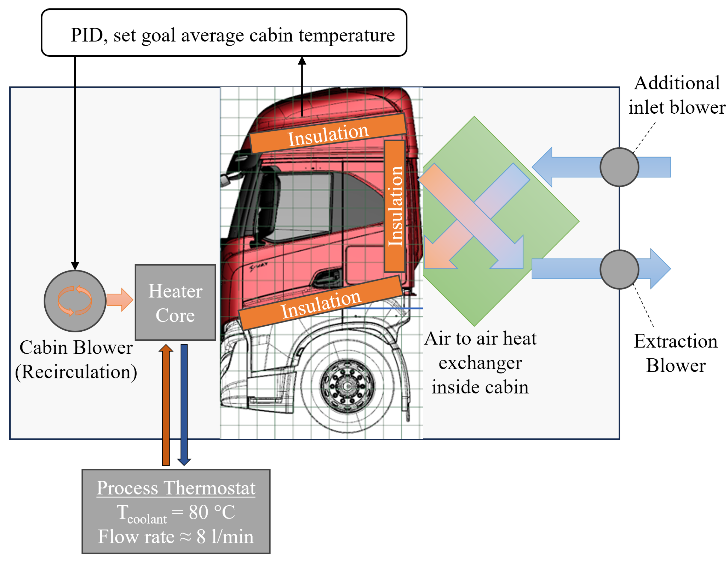
Figure 2.
C concentration with two occupants at 100 /h fresh air volume flow rate.
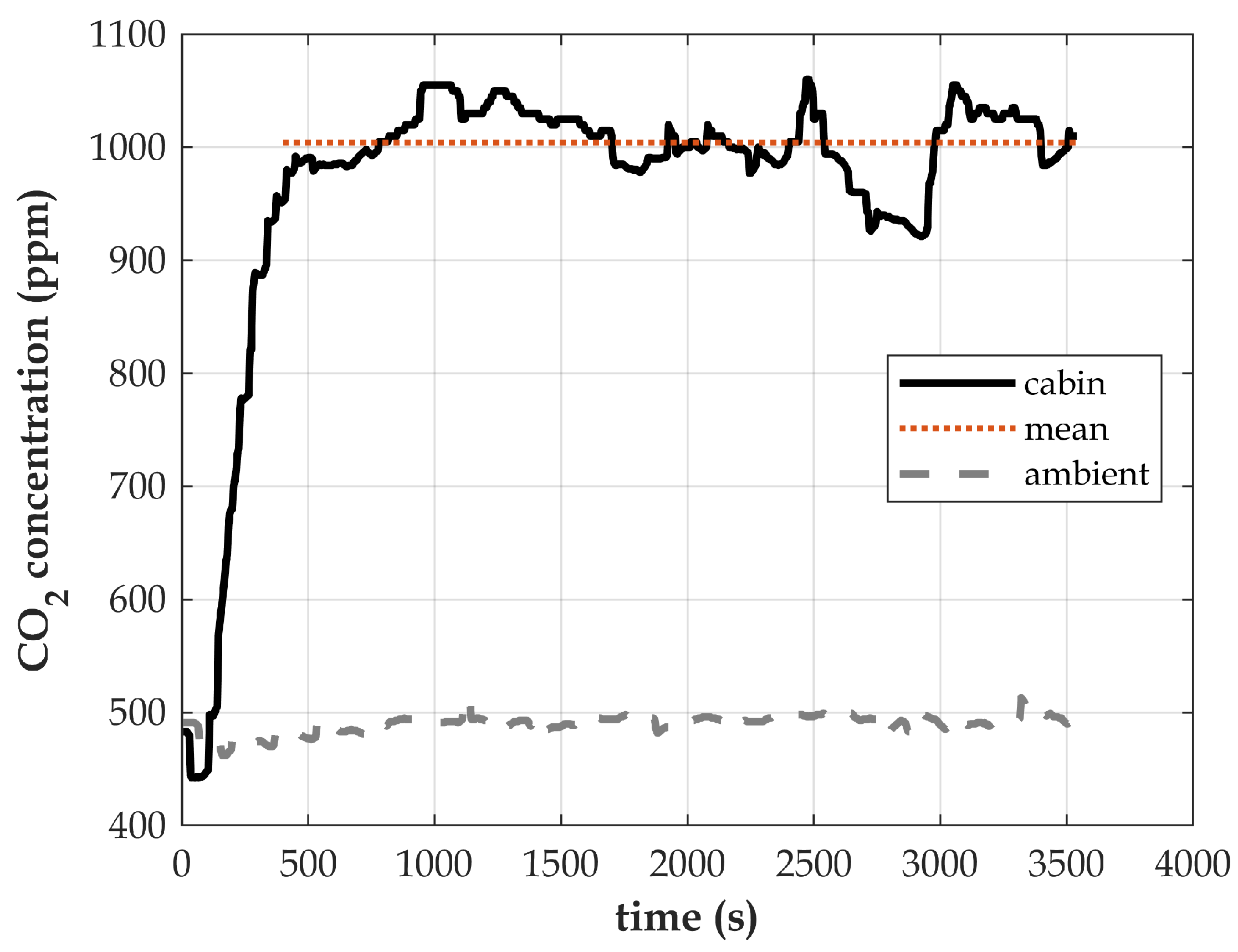
Figure 3.
Total power consumption of the HVAC system for the different cases.
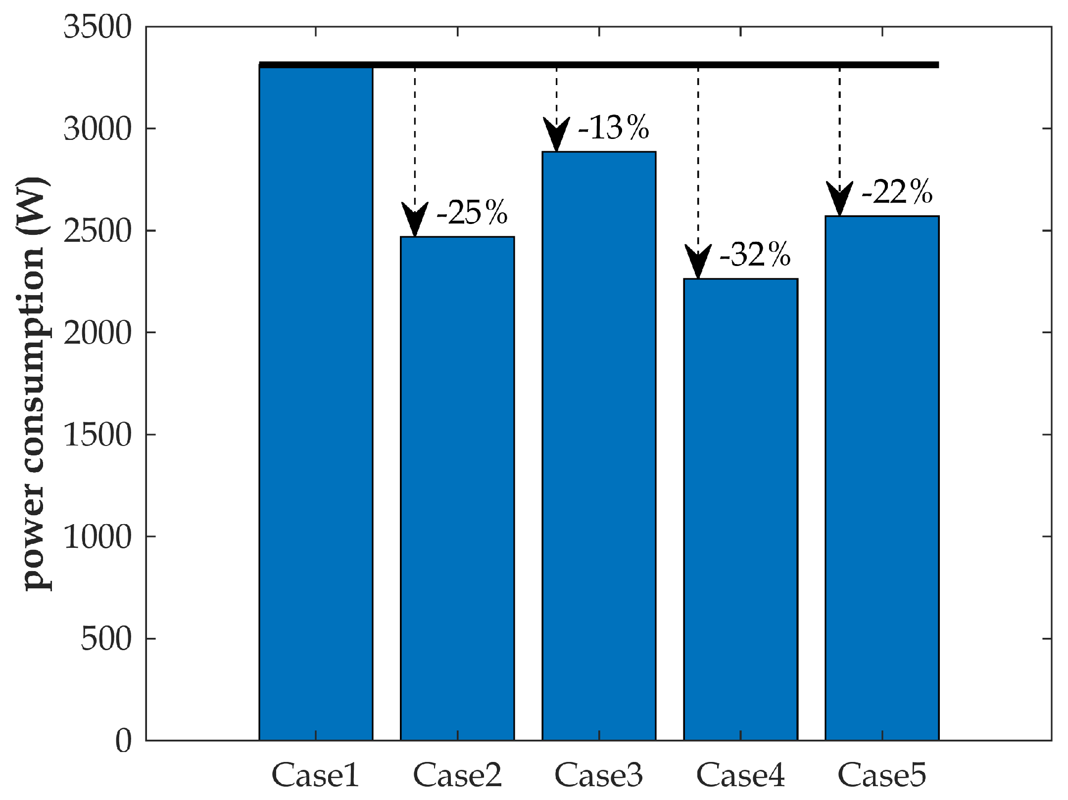

Table 1.
Description of the test cases.
| Case1 | Case2 | Case3 | Case4 | Case5 | |
|---|---|---|---|---|---|
| Improved insulation | No | No | Yes | Yes | Yes |
| Recirculation mode | No | Yes | No | Yes | Yes |
| Air-air heat exchanger | No | No | No | No | Yes |
Disclaimer/Publisher’s Note: The statements, opinions and data contained in all publications are solely those of the individual author(s) and contributor(s) and not of MDPI and/or the editor(s). MDPI and/or the editor(s) disclaim responsibility for any injury to people or property resulting from any ideas, methods, instructions or products referred to in the content. |
© 2024 by the authors. Licensee MDPI, Basel, Switzerland. This article is an open access article distributed under the terms and conditions of the Creative Commons Attribution (CC BY) license (http://creativecommons.org/licenses/by/4.0/).
Copyright: This open access article is published under a Creative Commons CC BY 4.0 license, which permit the free download, distribution, and reuse, provided that the author and preprint are cited in any reuse.


