
Submitted:
29 November 2024
Posted:
02 December 2024
You are already at the latest version
Abstract
This paper analyzes first the general statements accepted in the technical literature concerning the complete dynamic decoupling of constant air-gap multiphase machines with space harmonics (usually resorting to the instantaneous symmetrical components, ISC) and shows that they are not correct, since they only hold (and only with good approximation) for the particular case of converter-controlled machines. It then deduces in a rigorous theoretical way the correct conditions in all cases for both a precise and an approximate decoupling of multiphase machines and thereupon verifies them through numerous simulations. To do that, the Space Phasors Theory (SPhTh) is applied, whose true core, often unknown or misunderstood, is clearly explained. Preceding this point, the concept of dynamic phasor of g sequence, which is widely used in the SPhTh, is introduced and the necessary historical and critical review of the ISC is undertaken.
Keywords:
AC machines
; Instantaneous Symmetrical Components
; Space Phasors Theory
; Multiphase machines
1. Introduction
The physical meaning and the history of the instantaneous symmetrical components (ISC) in their application to the analysis of electrical machines transients have been detailed in [1], which together with [15], is the starting point of this work. As indicated there, the theory of symmetrical components (SC) originated with Fortescue, who published it in a paper [2] which, including the discussions is 113 pages long, with more than 300 formulae. Although Fortescue pointed out that his formulae could be applied to electrical quantities of arbitrary time variation, he only applied them in [2] to the analysis of many practical industrial cases of rotating machines in asymmetrical steady state.
In 1954, Lyon published his book [3] for analyzing the transients in three-phase machines, using as essential tool the SC formulae in [2], but applied to the instantaneous values of the electrical quantities (an application field of the SC unexplored until then, but mathematically correct, as Fortescue had already pointed out). Thus, the instantaneous symmetrical components (ISC) for three-phase machines were “rediscovered” for the electrical engineering world in their most powerful1 version and presented as excellent, but mere analytic tools for transients study. Their use within this context led Lyon to no longer call them a decomposition but a transformation. Three years later, Hochrainer, in his book [5], introduced for the German-speaking area the ISC, and also presented them as a mathematical transformation without any underlying physical meaning ([5], page 279). Later on, White and Woodson extended the transform to multiphase machines considering no saturation and only the case of sinusoidal distribution of the air gap induction ([6], pages 546 and 569).
The ISC of currents (analogously for voltages and flux linkages) of an m-phase symmetrical winding are [6]:
Where . From (1), the expression for the general ISC, , (with k = 0, 1, 2…m-1) is:
It is apparent that the ISC in (1) are conjugate complex quantities. In spite of that, when analyzing in [3] the three-phase machines, the pair of conjugate complex equations systematically appear, although one of these equations is simply superfluous. This fact was rightly criticized in the long paper [7], whose title, which takes the form of a question, clearly anticipated the debate contained therein, and underlined the remarkable advantages of the method proposed one year earlier in [8].
In their book [8], Kovacs and Racz (who also assume the hypothesis of no space harmonics), instead of starting from abstract mathematical transformations, analyzed first in all detail ([8], pp 61-67), from a physical perspective, the dynamic m.m.f. space wave produced by a three-phase winding and deduced its expression, which has a direct correlation with the time phase currents. In addition to its formula and its physical meaning, they characterized this space wave by a graphical tool they called “current space vector”, I (in German: Stromraumvektor). Later on, as they could not find space quantities related to the phase flux linkage and voltage time quantities, they introduced very briefly and only mathematically, by a mere formal analogy to I, the so-called voltage (U) and flux linkage (Ψ) “space vectors” ([8], page 75). Yet, although there was no physical meaning for them in terms of space waves, the authors in [8] profusely used them together with I in a graphical manner to explain the three-phase machine equations. This new graphical viewpoint of approaching and illustrating the transients, in contrast to the abstract matrix transformation perspective, provided a much better insight into the phenomena, in addition to the reduction of the number of equations. As to this last point, notice that, mathematically, the “space vectors” I, U, and Ψ in [8] are the first ISC of the machine currents, voltages, and flux linkages, which are sufficient (no need for the second ISC, as discussed in [7]), to characterize the three-phase machine dynamic equations, provided there are no homopolar components.
On the other hand, many years earlier, following a quite different approach, Park had introduced [9] his complex quantities for the sole purpose of simplifying the dynamic three-phase machine equations. And as it turned out that the expression of the “space vectors” in [8] coincided with their homologous complex quantities in [9], Park's complex quantities were then renamed in quite a few cases as “Park vectors”, although it was not uncommon to ignore the process and the physical reality behind this change of name.
In any case, it should be noted that in the discussion to [9], Kron already indicated in passing that Park's current complex quantity could be considered as a “current linear density wave” ([9], page. 354]). However, in his later highly abstract publications, Kron does not seem to have been interested in defining or searching for similar correlations between other (if at all existing) machine space waves and Park’s voltage and flux linkage complex quantities.
So far, with the exception of [6], all of the above references [3,5,6,7,89] refer to ISC or to “space vectors” (a conceptually incorrect name, since they are not vectors as understood in physics, but complex quantities that symbolize space waves) in three-phase machines. In [10], Stepina stated that any of the current ISC in a multiphase machine with space harmonics was associated with a specific group of m.m.f. (or of current linear density) space waves. He gave their mathematical relationship and, as a practical and useful example, he detailed the groups of current sheet space waves corresponding to each one of the current ISC in m-phase windings ranging from m = 2 to 7 ([10], Table 1, page 392).
Stepina´s contribution was a very valuable contribution in that it linked space waves (“space vectors”) and ISC of the currents in the very general case of multiphase machines including their current sheet harmonic waves. Nevertheless, as to the ISC of Ψ and U, it continued to be impossible to make any physical sense of them, even in the simplest case introduced in [8] of three phase machines without space harmonics. Yet, just these two “space vectors” are by far the two most important ones, and understanding and deducing their relationships to both, their machine space waves and the time values of the corresponding phase quantities in the general case (multiphase machines with spaces harmonics), is essential for understanding how the machine actually works and how to “untangle” its intricate structure. This “untangle” is precisely the base for the decoupling of the multiphase machine, as shown in this paper.
This paper is as follows: Section 2 analyzes the general statements accepted in the literature as to the complete dynamic decoupling of constant airgap multiphase machines with space harmonics, shows their starting inconsistency and rejects them. The decoupling problem and its correct answer are addressed in Section 6 and Section 7 by means of the SPhTh. Before doing it, it is unavoidable to become familiar with the suitable analytical tools and the true core of the SPhTh, often unknown or clearly misunderstood. This previous task is carried out in sections 3-5. Section 3 introduces the concepts of dynamical m-phase system (DmPhS) of g sequence and its dynamic time phasor. Through that, Kapp´s time phasor concept is extended from steady to transient states, whereby the notion of “g” sequence must also be included. Next section determines the formulae of all of the dynamic time phasors necessary to characterize the corresponding electrical quantity of a symmetrical multiphase system in the most general case (this, moreover, gives a first physical interpretation of the ISC). Section 5 shows in a precise way the true core of the Space Phasor Theory (SPhTh). It defines first the Ψ and U space phasors as symbolical representations of the two most important machine internal (space waves) quantities and calculates thereafter their correlation with their homologous time phase quantities. Relying directly on the results of sections 3-5, section 6 shows how to “untangle” the intricate structure of the multiphase machine and to decompose it into several simpler and independent machines. This section also gives a second and deeper physical interpretation of the ISC. Finally, Section 7, which is by far the longest one, discusses theoretically and establishes thereafter the conditions in all cases for both, a precise and an approximate machine decoupling, which is then confirmed by numerous simulations.
2. On the Incorrect Statements as to the Method to Obtain Complete Dynamic Decoupling of Multiphase Machines with Space Harmonics in the General Case
The authors totally agree with the statement ([11], page 492), that “Probably, the most comprehensive treatment of the modelling procedure (for multiphase machines) at a general level is available in [6]”.
In chapter 10 (“General Analysis of the n–m Winding Machine”) of the above book [6], resorting to the ISC and assuming that phase windings are “cosinusoidally distributed in space on a smooth magnetic structure and that the mutual flux density between rotor and stator produced by them is a sinusoidal function of space” (page 569), its authors, after a rigorous mathematical process, conclude: “Therefore, the only quantities which must be considered to determine electromechanical energy conversion properties are the positive- and negative-sequence currents of an equivalent two-phase machine...Since all the other (n + m – 4) symmetrical component volt-ampere equations except the + - components for stator and rotor are linear and non-torque producing, it follows that the symmetrical component transformation reduces the n – m machine to an equivalent two-phase energy converter plus a set of independent networks (n + m – 4) in number” (pages 588 and 590).
In today´s literature, it is usual to express the above conclusions in another equivalent way. Put it simply: leaving aside the homopolar components, in the m-phase machine there are (m – 1)/2 so-called mutually orthogonal bidimensional subspaces (m odd), of which only one is involved in the torque generation. Or alternatively: there are (m – 1)/2 pairs of current and voltage components. Only one of them (α-β components) produces torque, being each one of the remaining non-torque producing pairs (x-y components) completely decoupled from all the others.
Relying on these conclusions, deduced and only valid under the assumptions very clearly and precisely indicated in [6], a very audacious and qualitative leap was made; namely, it was stated that one can use the additional x-y components of the machine to increase the torque density by utilizing its harmonic fields, being the dynamic torque produced by each x-y component independent from all the others ([12], page 637; [11], page 495; [13], page 1896). Stator and rotor phase number may be different, as usual in most squirrel cage motors.
It would be unfair and a sign of ignorance not to recognize the important contribution of this idea in developing multiphase machines useful and practical applications.
Yet, this idea or statement, which is about twenty years old, has been accepted, it is true, worldwide in the technical literature, but, surprisingly, it has never been mathematically proven. This, on the other hand, could hardly have been done, simply because it lacks a correct theoretical base.
Indeed the statement above requires that there are air-gap harmonic fields. Yet, at the same time, the results and formulae in [6], on which it fully relies, apply and have been deduced only for machines without harmonic fields (sinusoidal air-gap induction). This clear contradiction alone openly questions the general validity of the claim.
3. Definition of a Dynamic M-Phase System of g Sequence. Extending the Concept of Kapp’s Time Phasor to Dynamic States of Polyphase Systems
In the steady state of alternating current circuits, sinusoidal quantities are very often involved. As well known (Figure 1), their instantaneous values may be determined by the projection on a Cartesian axis of a “rotating vector” (Kapp´s time phasor) with constant amplitude and speed [14]. Let us first extend Kapp´s phasor concept to transient states.
By definition, the m quantities (m currents, m voltages, etc.) of an m-phase symmetrical winding are said to constitute a dynamic m–phase system (DmPhS) of “g” sequence, if they meet the following equations (γ = 2π/m):
where x(t) and ε(t) can be arbitrary time functions. For g = mq+1, mq+2, mq+3, etc., where q is any positive natural number, the values in (3) are the same as for g= 1, 2, 3, etc., respectively. For g = mq or zero, the system is called the homopolar DmPhS.
A DmPhS of “g” sequence only has two independent variables, x(t) and ε(t). Thus, it can be fully characterized by a new mathematical tool (a complex time quantity) called in [15] “dynamic time phasor of a DmPhS of “g” sequence:
Variables x(t) and ε(t) determine the amplitude and position in the complex plane of the dynamic time phasor. Let us first consider a DmPhS with g = 1. It is apparent from (3) and (4) that in this case, the quantity of any phase is obtained by simply projecting the phasor onto the phase axis.
Now let us fictitiously exchange the phase positions in a cyclic manner according to the g-value, that is, to go from phase y to the next phase y+1, one has to traverse the angle gγ, instead of γ (see Figure 2). Keeping this in mind, it is clear that in a DmPhS of g sequence, the quantity of any phase with its axis placed at its actual position, y, is obtained by simply projecting the phasor onto the axis that would belong to this phase after having performed with g sequence the cyclic exchange of phases. Mathematically (stands for “real part of”):
The sum of currents, voltages, etc., of several DmPhS´s, S1, S2, etc., of the same sequence, g, produces a DmPhS which also has the g sequence. The dynamic time phasor of the resultant DmPhS equals the vectorial sum of the dynamic time phasors associated with S1, S2, etc. Notice that although functions x(t) and ε(t) in (3) may be arbitrary and very different for the different systems S1, S2, etc., the statement above on the vectorial sum of dynamic time phasors always holds.
The g and (m – g) sequences are called complementary sequences. Any DmPhS of g sequence can be converted ([1], page 336) into a DmPhS of (m – g) sequence according to the formula (* stands for conjugate complex):
These formulae show that DmPhS´s with equal or complementary sequences can be added up and the result can be characterized by just one dynamic time phasor.
The dynamic time phasors can be regarded as a powerful extension of Kapp´s steady state time phasors. They can be dealt with mathematically (complex time-varying quantities) and graphically (vectorial addition), just as done with Kapp´s classical phasors.
With regard to this point, notice too that any DmPhS of g sequence is the result of projecting with g sequence into the system phases a phasor whose amplitude and speed may vary in arbitrary manner2. The DmPhS is fully characterized by the phasor. This fact provides, when operating with transients, a powerful tool, both for their mathematical as well as their graphical and visual analysis.
4. Dynamic Time Phasors of Symmetrical Multiphase Systems with Arbitrary Currents
Since the essential features of dynamic time and space phasors can be best illustrated with m-phase systems having an odd number of phases, henceforth in this paper, m will always be assumed odd. Phase 1 axis always coincides with the real axis.
Let it be a three-phase symmetrical winding with three arbitrary currents (or voltages, flux linkages, etc.) without homopolar components, i1(t), i2(t) and i3(t). It must be possible to obtain these currents through the projection of a dynamic time phasor onto the phase axes, that is (γ = 2π/m):
Indeed, since the sum of the phase currents is zero, there are only two independent variables and equations in (7), which just determine magnitude and angle of IA. After a simple calculation, it follows:
Let it be now a 5-phase winding with arbitrary currents, but again without homopolar components. Since there are four independent currents, it seems at first sight that the two independent phasors:
would suffice to determine the current of any phase (sum of the two phasor projections onto the phase). Yet, this way, all the currents would actually be derived from the projections of one only effective phasor (sum of IA and IB). Therefore, and for the purpose of specifying the phase currents, it is necessary to impose the additional condition that IA and IB also differ from one another as to the way in which their projections on the winding phases take place. This could be done in many ways. The most direct one is to imagine that the phase positions are exchanged in cyclic manner, depending on the phasor considered: e.g., for phasor IA, the phases are placed in their actual sequence, 1, 2, 3, 4, 5 (that is g = 1), whereas for IB they are assumed to be in the sequence 1, 4, 2, 5, 3, (that is, g = 2.). Again, after a rather simple calculation, it follows (more details in [15] and [1], page 337):
Notice that, according to the developments in previous section, IA and IB are, simply, the dynamic current phasors of sequence 1 and 2 of the 5-phase winding. In other words, through the phasors of sequence 1 and 2, the original five arbitrary currents system without homopolar components has been decomposed into two independent systems, each of them characterized by one only dynamic time phasor. Obviously, only dynamic phasors of the same sequence can be vectorially combined and added up.
This process can be easily generalized to symmetrical windings with an arbitrary number of phases, m, and without homopolar components. In that case, (m – 1)/2 phasors of sequence g = 1, 2…(m – 1)/2 are needed. The formula for the general dynamic time phasor of g sequence is given by (details in [1,15]):
As seen in previous section, the dynamic currents (or voltages, flux linkages, etc.) in all of the phases of a symmetrical m-phase winding can be characterized by just one dynamic time phasor if, and only if, these phase currents constitute a DmPhS of g sequence. Yet, even in the most general case of arbitrary currents, the set of the phase currents can always be characterized by (m-1)/2 dynamic time phasors of sequences g= 1,2...(m-1)/2 plus, if necessary, a homopolar dynamic time phasor. In other words, the overall system has been decoupled, in the most general case, into a homopolar system and (m-1)/2 completely independent DmPhS's, each of which is defined by its dynamic time phasor, whose formula is given in (11).
Except for a factor 2, formula (11) coincides with (2) of the ISC. Thus, the ISC have a first important physical meaning: they are the set of dynamic time phasors that decouple and fully describe, mathematically and graphically, the time evolution, in the most general case, of the phase quantities in an m-phase symmetrical winding.
5. The Space Phasors Theory and the Fundamental Ψ and U Space Phasors
The approach overwhelmingly used today for machines transient analysis is the magnetic coupling circuit approach (MCCA) which regards the machine as a network made up of resistances and inductances, many of which vary with the rotor position. This network is dealt with by means of abstract and complex matrix transformations.
By contrast to the MCCA, the SPhTh introduced in [15] states that a machine can also be regarded as an electromechanical device that produces electromagnetic (field) waves with a restricted propagation capacity, namely they are forced to turn inside its air-gap. These space waves:
- Should be the most important and dominant ones.
- Should be characterized by dynamic space phasors.
- Should be easily correlated with their corresponding machine time phase quantities.
These requirements are fully met by the space waves of the magnetic vector potential, A, and of the scalar electric potential difference, φ.
Thus, the SPhTh in [15] completely rejects space phasors to be mere mathematical entities without physical meaning (an idea always found for phasors Ψ and U in papers on three-phase machines, let alone in case of multiphase machines). Its starting point is just the opposite: space phasors are always to be introduced representing fundamental and clearly defined machine internal (space) quantities.
As to these quantities, the extraordinary importance of A and φ was already strongly stressed by the Nobel laureate Feynman, who wrote: “the vector potential A (together with the scalar electric potential, φ that goes with it) appears to give the most direct description of the physics.” ([16], page 15-14). The key role played by A and φ in electromagnetics can also be seen very clearly in the, in our opinion, excellent and extraordinary book [17].
To put into practice in our case Feynman´s fundamental idea, let it be a long (negligible end effects) salient pole machine with axial conductors at the cylindrical stator surface. From Maxwell´s equation:
it follows that the total flux linkages of an arbitrary stator single turn, “ab” (Figure 3) of any stator phase is given by:
That is, Ψab is the sum of the vector potential values, Az, at the positions of the two turn conductors, multiplied by the machine length, l. (Notice that A and B are constant in the axial direction, z, since, as usual, the magnetic field distribution in the machine is assumed bidimensional). Thus, the flux linkages of the whole phase are simply the algebraic sum of the A values at their conductor positions.
Notice that (13) always holds, no matter the rotor shape or whether the magnetic circuit be saturated or not. Thus, if the magnetic vector potential wave at the stator surface is known, the phase flux linkages are obtained immediately from this space wave in the most general case.
Analogously, if the space wave of the stator electric potential difference in axial direction, φz, is known (potential difference between the two ends of an axial straight conductor), the total voltage of any stator phase K is obtained by simply adding up the electric potential difference values at all of the conductor positions:
Dynamic space phasors are excellent tools to operate with the space waves in (13) and (14). By definition, a space phasor is an oriented segment in the complex plane that symbolically represents the spatial sinusoidal distribution of an internal machine quantity. The phasor always points to the positive maximum of the wave (case of bipolar waves) and its modulus is equal to the wave amplitude. Both the wave amplitude and speed may vary arbitrarily.
Usually, the internal quantity is not sinusoidal. Then a harmonic space phasor is assigned to each space harmonic of its Fourier expansion. To this end, a domain transformation is defined in such a manner that any angle, α, in the machine domain, becomes an angle να (ν = absolute harmonic order) in its corresponding phasorial domain. Notice that through this transformation (which boils down to transform the mechanical angles into electrical ones) any multipolar wave is characterized by one only space phasor (the same coordinate in the phasorial domain corresponds to all its positive crests in the machine, see Figure 4).
Let it be a sinusoidal wave with ν=hp pole pairs distributed over the stator cylindrical surface of a salient pole machine (an induction wave, a wave of electric potential difference, etc.). If xhp(t) is the instantaneous amplitude of the space wave and ε(t) defines any of its instantaneous positive crests in the machine, the wave expression becomes:
On the other hand, this space wave of hp pole pairs, as just stated, is fully characterized in its phasorial domain by its space phasor, whose expression in the most general case is:
From (15) and (16) it follows immediately:
That is, the stator quantity (e. g. induction, electric potential difference, etc.) at an axial straight line of the stator surface specified in the machine domain by the angular coordinate α is given by the projection of its space phasor on the straight line defined by hpα in the phasorial domain (see Figure 5).
Thus, according to (17), the voltage of one conductor produced by the electric potential difference wave (the “voltage wave”) with hp pole pairs is equal to the projection in the phasorial domain of its voltage space phasor onto the conductor. Therefore, the voltage of any stator phase of an m-phase symmetrical winding due exclusively to this voltage wave is given by the sum of each one of the projections of its voltage space phasor, Uhp, onto the phase conductors. This sum turns out to be equal to the projection of the phasor Uhp onto the phase axis multiplied by Zξh, where Z is the number of the phase conductors connected in series and ξh is the winding factor for the harmonic of relative order h. Finally, the total voltage in (14) of any of the m-winding phases is easily obtained through the sum of the projections of all of the voltage phasors onto the phase axis, multiplying each projection by its corresponding Zξh.
Analogous process of sums of projections holds for the Ψ phasors and their associated phase flux linkages.
6. Untangling the Intricate Structure of the Multiphase Machine
All of the sums in the previous section (a rather simple calculation) have been carried out in [15]. The main results are as follows (see, among other formulae, the mathematical deduction, implications and interpretation of equation (23) in [15]): let it be, e. g., a 7-phase symmetrical winding with p pole pairs placed at the stator of a salient pole machine. Each of the voltage waves (that is, electric potential difference space waves in axial direction) with p, 8p, 15p, etc., pole pairs (with other words, each of the harmonic waves of relative order h = 7q + 1 with q = 0, 1, 2, 3, etc.) only produces in the phases of the 7-phase winding a voltage DmPhS of g=1. Likewise, each of the waves of order h = 7q + 2; h = 7q +3, etc., produces in the phases a voltage DmPhS of g= 2, 3, etc., respectively.
Therefore, for a 7-phase winding, all of the electric potential difference waves can be classified into seven independent families. The instantaneous amplitudes and positions of the different waves belonging to the same family are, in the general case, quite different from one another. However, all of them originate DmPhS´s of the same sequence, and therefore, as explained in sections 3 and 4, can be added up to give a resultant DmPhS of this same sequence. Thus, the combined action of all of the waves of a family on the voltages of the winding phases can be characterized by just one effective voltage space phasor of the family. Or alternatively: the resultant voltage DmPhS in the polyphase winding produced by a whole family of waves can be imagined to be produced by one only effective voltage space wave, the phasor of which is just the effective space phasor of the family of waves.
Moreover, the two voltage DmPhS´s produced by the families with h = 7q ± 1 are DmPhS´s of complementary sequence. Hence, they can be added up so that just one space phasor suffices to characterize the combined action of this group of two families. The same statement applies to the families with h = 7q ± 2 and h = 7q ± 3. Thus, the combined effect of all of the electric potential difference waves on the voltages of the seven phases in any dynamic state is fully characterized by just three effective voltage space phasors (plus one homopolar phasor, if necessary). These conclusions apply too to the magnetic vector potential space waves (space phasorsΨ), and can be extended to a symmetrical winding with an arbitrary number of phases [15]. It should be underlined that these groups of UandΨ space waves, mathematically established in [15] for the first time, coincide with the groups determined by Stepina for the I space waves following a quite different path, which can only be applied to the currents [10].
In summary, the phase voltages of an m-phase symmetrical winding placed on a cylindrical stator or rotor are completely defined by the projections, in their phasorial domains, of the (m-1)/2 stator or rotor effective voltage space phasors (plus a homopolar phasor, if necessary) on the axes of these phases. This also applies to the flux linkages and currents, no matter how arbitrary their time variations may be. Yet, this is exactly the same as with the (m-1)/2 dynamic time phasors calculated in Section 4. Thus, mathematically, the expressions of the effective space phasors must coincide with that of the dynamic time phasors in Section 4, which, in turn, coincide with the formulae of the ISC multiplied by 2. This, in addition, gives a second a deeper physical meaning of the ISC: they symbolize the current linear density, the electric potential difference and the magnetic vector potential space waves in the m-phase machine (more details in [1]).
If we apply a current to a phase placed on a cylindrical stator or rotor and we know the spatial distribution of its conductors, we can determine any space harmonic (and its space phasor) of the current sheet wave produced by the phase. This is not the case with the voltage space wave. Indeed, if we know the phase current, we know the current in each one of its conductors (which makes it much simpler to cope with I than with U waves), whereas in the case of an applied voltage we do not know the individual conductor voltages, but only their sum. That is the reason why only the effective voltage space phasors of an m-phase winding can be determined from layout and voltages of its phases. On the contrary, under similar circumstances, we can calculate not only the effective current space phasors, but also the individual space phasors of all of the space harmonics of the current sheet produced by the m-phase winding. Moreover, once these formulae ([15], page 87) are calculated, it is easy to prove ([15], page 92) that, if the currents applied to an m-phase winding constitute a DmPhS of g sequence, then all the current sheet space waves produced by them are, exclusively, of relative order h = qm ± g.
It is now convenient to summarize (more details in [15]) the main results that apply to constant air-gap multiphase machines (either permanent magnet synchronous machines PMSM, induction IM or doubly fed asynchronous machines DFAM) with m phases in stator and rotor and without homopolar components (always to be avoided):
For a three-phase machine, there is only one space phasor U in the stator (all of the corresponding harmonic space waves belong to the same group, h = 3q ±1 with h odd) and one in the rotor. The same applies to the Ψ and I effective space phasors. These two (U,Ψ, I) triads fully describe the machine behavior.
- (a)
- Each of the (m-1)/2 U space phasors in stator (or rotor) characterizes an effective voltage space wave in the stator (or rotor). More precisely: it synthesizes through an equivalent wave the contribution to the voltages of the stator (or rotor) phases due to a specific group of electric potential differences space waves existing in the stator (or in rotor). Analogous considerations apply to the Ψ and I space phasors.
- (b)
- The mentioned total contribution to a phase of any of the waves group is obtained through a very simple procedure: by projecting its phasor onto the phase axis.
- (c)
- Each one of the independent groups of space waves in stator, together with its homologous group in rotor, can be associated with a fictitious machine which, therefore, has one only set of phasors (U,Ψ,I ) in stator and one in the rotor, just as in three-phase machines.
In summary, each one of the different triads (U,Ψ, I) of effective dynamic space phasors in the multiphase machine is related to one specific and independent group of space harmonics. This physical reality, analyzed in detail in [15] constitutes the base that enables to “untangle” the structure of a constant air-gap multiphase machine and to split it into a equivalent set of (m-1)/2 fictitious machines, mechanically coupled but electrically independent.
A possibility that is usually the first that comes to mind to describe any one of these fictitious machines is that of a machine whose winding factors are all zero, except for those corresponding to the harmonics belonging to the wave group associated with the machine (e.g., ). There is also a second and more interesting possibility: indeed, in the most general case, an m-phase induction machine (IM) without homopolar components can be fed by a voltage system for the definition of which (m-1)/2 DmPhS´s (or (m-1)/2 dynamic time phasors) are required. Within this context, each of the fictitious and mechanically coupled machines can be considered to be equal to the actual machine but imposing the condition that it can be fed by only one of these DmPhS’s of voltages. Obviously, both pictures or approaches lead to the same set of air-gap space harmonics, are equivalent and can be easily implemented in a program.
It should be pointed out that the authors in [18] dealt with the simpler case (neither phases number nor windings in the rotor) of PMSM. Following a completely different approach, they arrived for the mentioned particular case of PMSM at analogous results than the ones in this paper. Indeed, with the additional simplifying assumption (unnecessary in the SPhTh) that the stator currents do not modify the wave of the EMF induced in the stator coils by the rotor magnets, they proved in a mathematically elegant manner that a PMSM can be decomposed into a set of simpler independent fictitious machines.
As well known, only the interaction of stator and rotor space waves with the same pole number produces torque. Assume a 7-phase DFAM. If one applies, exclusively, e.g., a current DmPhS of g = 2 (or g=5) to the stator and another one to the rotor, the space waves (and their associated torques) of the stator and rotor space waves groups with h = 7q ± 2 can be controlled in any dynamic state without modifying the waves of the remaining groups. This is the physical base underlying the decoupled control of the multiphase machine.
7. Establishing and Verifying the Decoupling Conditions for Constant Air-Gap Multiphase Machines with Space Harmonics
7.1. Precise Decoupling
Let it be a constant air-gap machine with a multiphase winding in the stator and another in the rotor. The theoretical assumptions are the same as in chapter 10 of [6], but eliminating the hard restriction of sinusoidal air-gap induction, that is, the windings do not have, as postulated in [6], an unreal and ideally sinusoidal distribution in space, on the contrary, all the air-gap induction harmonics produced by them are taken into account. (Note in passing that, consistent with this fact, the analysis field of the SPhTh goes far beyond the one in [6]). The phases of each winding are, as in [6], equal, and symmetrically and evenly spaced (the angle between any two consecutive is 2π/m).
In a symmetrical machine without homopolar components and mstr=mrot = 3, there is in the stator winding (the same applies to rotor) only one DmPhS of flux linkages and another one of voltages, with the sequence g=1. Therefore, all the individual magnetic vector potential and electric potential difference space waves in stator, no matter their changes of amplitude and speed (arbitrary transients) must produce DmPhS´s of this sequence. In a m-phase winding, however, there are several DmPhS´s of Ψ and U, which are mathematically and graphically fully characterized by their corresponding dynamic phasors. Since these DmPhS´s are independent of each other, as underlined at the end of Section 4, there must be groups of space waves, which are also independent of each other, and which produce the existing DmPhS´s. This is one of the main physical ideas underlying the paper [15] to untangle the intricate structure of the multiphase machine and address the problem of its possible decoupling.
Applying the key concept of a DmPhS of g sequence, or, better expressed, on the base of the DmPhS´s of flux linkages and voltages that they produce in a multiphase IM, the field harmonics of its stator winding (the same applies to rotor) must necessarily be distributed among several independent groups. And this, indeed, has been mathematically proven in the SPhTh ([15], page 85). The relative order, h, of the harmonics belonging to the same group meet the equation h=qm ± g. According to this fact, it is evident that, if mstr ≠ mrot, the decoupling of the multiphase machine by pairs of homologous groups of stator and rotor space waves is mathematically impossible. The reason is, simply, that the field harmonics belonging to one only stator waves group have their rotor counterparts distributed among several rotor groups; and conversely.
The condition mstr = mrot, required for a precise machine decoupling, theoretically deduced in the preceding paragraphs, has also been checked with the help of a very complete program [19]. This program starts from the groundwork of the one used in [15], based on the SPhTh, but it is more powerful and much more versatile and faster. It can simulate transients of multiphase IM´s not only in healthy conditions, as was the case in [15], but also with any kind of rotor failures. In fact, the program has been applied in [20] to end-ring failures and its simulations have been tested and confirmed by failure measurements in real industrial installations. In this work, the simpler program variant of healthy motor is the one applied and consist of a dynamic model of an IM with constant air-gap, ideal magnetic circuit and arbitrary number of air-gap harmonics produced by the windings. The program has been implemented using MATLAB in a PC with an Intel Core i7-8700 processor and solved using a fourth-order Runge–Kutta method with a simulation step size of 10−4.
The verification procedure is based on the second approach described at the end of the previous section. Thus, first, the model is input with a voltage system sum of (mstr-1)/2 DmPhS’s of different g sequences, giving as output the total motor torque. Next, the same model is fed with each of these DmPhS’s separately, giving as output the motor torque for each case. Finally, these torques are summed and compared to the total torque. If both results overlap it means that both systems are equivalent, or in other words, that the m-phase machine can be decoupled into a set of (m-1)/2 electrically independent but mechanically coupled machines. Notice too that each of these machines can be treated as a three-phase machine in terms of the SPhTh, since only one effective space phasor is sufficient to characterize the action of all the waves of a given space quantity (e.g., Ψ for magnetic vector potential waves, U for scalar electric potential difference waves and I for current linear density waves).
Figure 6 shows the application of this procedure to the direct start-up under constant load torque of a wound induction motor (data in Appendix A) with p=2 and mstr=mrot=5, being the voltage DmPhS’s:
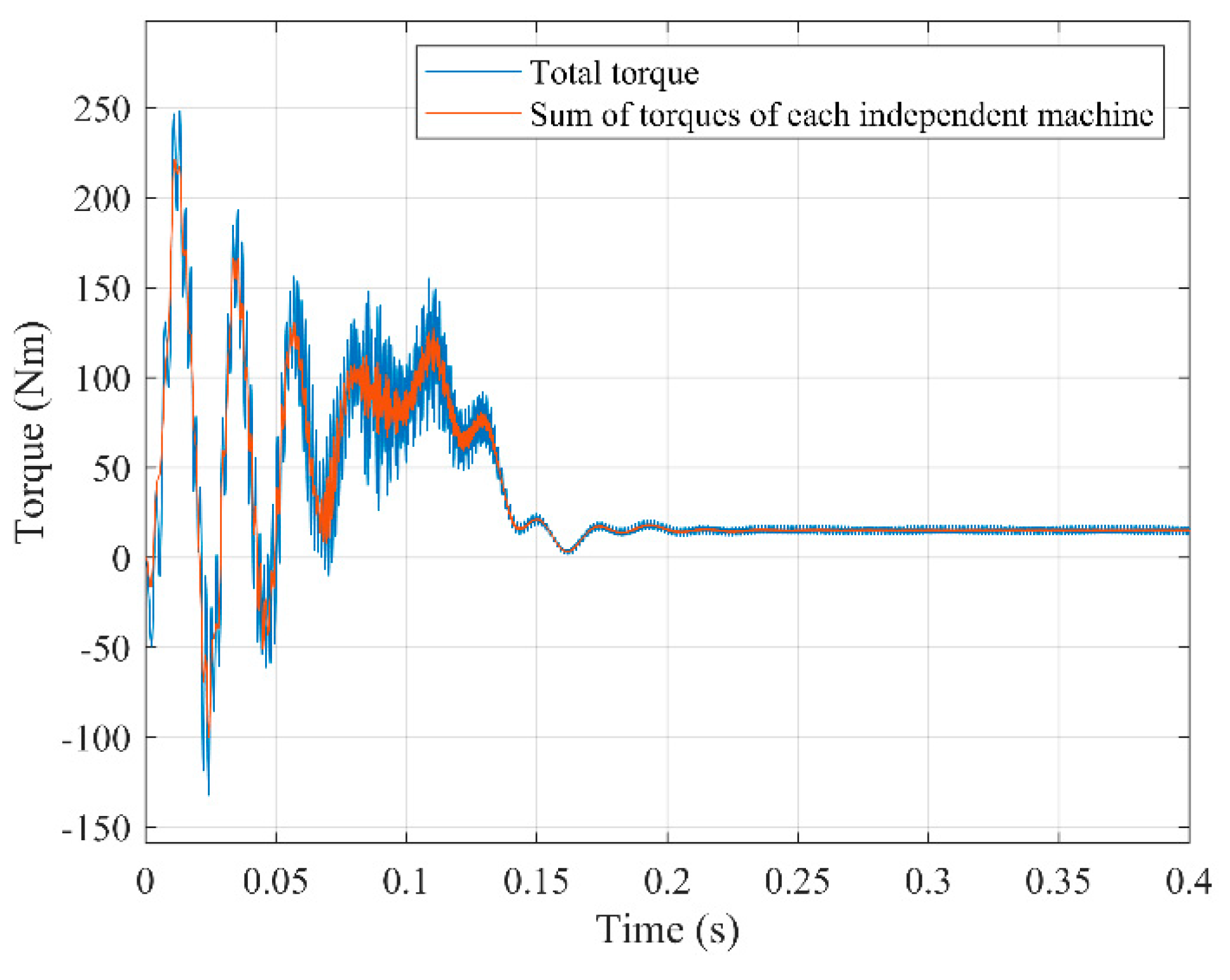
As can be seen, the electromagnetic torque is exactly equal in both cases (red graph overlapping the blue one). However, if the number of rotor phases is changed to 7, then Figure 7 shows that both torques clearly differ, meaning that the machine cannot be decoupled by pairs of homologous groups of stator and rotor space waves. As mentioned before, the reason is that the field harmonics belonging to a given stator group have their rotor counterparts distributed among several rotor groups. For example, in this case, the field harmonic of relative order h=9 belongs to the group of g = ±1 in the stator, while in the rotor it appears in the group of g = ±2. Similar discrepancies occur with many other harmonics as well.
The previous conclusions also apply, of course, to squirrel-cage motors. In this type of machine, assuming the almost universal case of B/p integer, the rotor can be regarded as a system of B/p phases, where B is the number of rotor bars and p the number of pole pairs. Figure 8 shows the application of the mentioned procedure to a squirrel-cage motor with 14 bars, p=2, mstr=7 and mrot=14/2=7, (remaining data in Appendix A) being the DmPhS’s:
As in the case of the wound induction motor, when the condition of mstr=mrot holds, there is also a perfect match between the torque resulting of feeding the machine with all the DmPhS’s simultaneously, and that obtained as the sum of torques when the machine is fed with each of the DmPhS’s separately. Likewise, when the condition is not satisfied, for example, if the number of rotor bars is increased to 22, the decoupling of the machine is mathematically impossible, as shown in Figure 9.
Thanks to the fast computation time of the program (typically around 25s for a 0.5s simulation), tens of simulations have been conducted with very different machines. Moreover, the input phase voltages had not only a sinusoidal, but also an arbitrary time evolution, expressed as sums of functions that meet (3). In all cases, the simulations confirmed the aforementioned conclusions.
In summary, as first deduced theoretically and then confirmed by tens of simulations (and shown for the first time in this paper, as far as the authors know), the condition for a machine decoupling both precise and valid for the whole working region (arbitrary slips) is that the equality mstr = mrot is fulfilled.
Since in almost all squirrel cage motors, mstr ≠ mrot, their decoupling, if at all possible, can only be appoximate and, most probably, only within a restricted working region. This issue is addressed in the next section.
7.2. Approximate Decoupling Within a Narrow Working Region—Equations of the Multiphase Machine
Let us start, in a first step, from a machine with m phases in stator and rotor. For each one of its fictitious machines, related to each group “g” of harmonic space waves, the voltage of any of its stator or rotor phases, K, must be equal to its resistive voltage drop plus the time derivative of its flux linkages, that is (x = stator or rotor):
Expressing these three time quantities by means of the projections of their corresponding space phasors onto the phase axis (see section 6, especially third bullet point (c) of that section), (20) turns into:
Since (21) is valid for any instant of time, any phase and for any number of phases, it follows for each one of the fictitious machines:
Equations (21) and (22) highlight two key advantages of the SPhTh:
- (a)
- Space phasors provide a deep physical insight into the machine behavior. This enables to "untangle" its complex structure, and it is just this previous knowledge that allows to directly write the equations of the machine with space harmonics as the ones of a set of electrically independent machines. Without this knowledge, the machine has to be analyzed as a single global system with a very intricate structure.
- (b)
- The very powerful step from (20) to equations (21) – (22) is extremely simple and straightforward.
In [21] very precise measurements of transient harmonic torques in three-phase IM´s connected to the mains were carried out. In addition to the measurements, it was also theoretically justified and confirmed by numerous simulations that the field harmonics effect on the machine torque may be very important in several industrial transients, like start up, unplugging, drop out, injection braking, etc. Yet, it was also proven that this effect is always negligible at low slips of the machine. This conclusion is also deduced in [22], page 208, using a quite different reasoning, and can be extended, with even more reason, to each wave group of the multiphase machine. This implies that in converter-controlled multiphase machines (always small slips, even in transients) it is acceptable to assume that only the space harmonics which are head members of their groups, that is, the harmonics with the lowest pole number, need to be considered. (e. g., for a 5-phase machine – which only has two groups – harmonics 1 and 3. For a 7-phase machine, harmonics 1, 3 and 5, etc.).
To reinforce and check the above conclusion from a different perspective, it is very useful to have a look at the, in the author’s opinion, valuable paper [23]. In it, the authors present a theoretical framework of analysis using matrix transformations. Relying on it, and in order to show through a practical example that in any induction (or more precisely: in any constant air-gap) multiphase machine the decoupling is always possible, they choose a machine with seven phases in the stator. They start then from the assumption that in this case “the flux produced by the rotor in the stator winding has a fundamental, a third and a fifth harmonic component” ([23], page 336), but without giving any mathematical proof or physical explanation that justify it. So, one has the right to ask: why choose just and only these three harmonics? What is the reason for not choosing, e.g., the first seven machine harmonics or other combinations? (In these other cases one can verify that there is no longer any decoupling). Likewise, when applying their procedure to a 5-phase machine, only the first and third harmonics may be present in order to achieve decoupling. And so on.
The useful and correctly proven decoupling of induction machines in the valuable paper [23] is actually based on the unstated assumption that only the space harmonics which are precisely the head members of the groups established in the SPhTh produce torque. Yet, this assumption is only acceptable for the narrow region of small slips ([21], page 74, [22], page 208). Thus, it is only this assumption that allows the approximate, but very practical decoupling of converter-controlled multiphase induction machines (always small slips, even in transients) by means of (m-1)/2 pairs of independent space harmonics. Moreover, in contrast to Section 7.1, in the particular case now under consideration, the decoupling does apply also to the structure mstr ≠ mrot. Indeed, even when mstr ≠ mrot, any pair of homologous stator and rotor head members is independent of all other analogous pairs, and it is only these pairs that produce torque in this case. Notice that the validity of an approximate decoupling at low slips is also clearly confirmed by Figure 7 and Figure 9: when the motor is close to steady state, the blue and red graphs practically overlap each other. Yet, out of this small region, if mstr ≠ mrot , as is the case with virtually all the squirrel cage motors, there is an important cross coupling between stator and rotor space waves that belong to different groups, as proven in the SPhTh [15] and as seen by comparing Figure 6, Figure 7, Figure 8 and Figure 9.
Now, instead of using, as done in previous paragraphs, the straightforward and very “visual language” of groups of space waves, let us resort to the abstract language of “mathematical subspaces”. Precisely formulated in this language, the second and most important contribution or thesis of this paper is the following: the claim or the statements that the machine structure is always equivalent to a set of mutually orthogonal bidimensional subspaces with only one harmonic per subspace must be rejected. These statements, although accepted without objection in the literature for some 20 years, have never been mathematically proven. This could hardly have been done since, as shown in previous paragraphs, they only hold, and only approximately (although with very good approximation) in the narrow region of small slips.
In spite of that, and as already written in section 2, it would be unfair not to recognize the positive impact of the above statements on valuable applications of multiphase machines. Yet, one should be aware that it has been a lucky coincidence that, so far, the decoupling procedure based on them has been applied and verified only in the field of converter-controlled machines. Certainly, this is, at least nowadays, their overwhelmingly used and most important industrial field. Yet, a technological circumstance is no reason in science to sustain and present, without any proof, theoretical principles or statements as having general validity, when they only apply to a particular case.
Moreover (and worse, in our opinion) such an approach also makes impossible to physically understand and explain what are the true reasons why, despite the fact that those general statements are incorrect, there is nevertheless a particular field in which they do hold up. Likewise, it prevents a deep physical insight into the intricate machine structure and how to correctly untangle it.
Equation (22) fully describes the electric behavior of any one of the fictitious machines with all its winding space harmonics. As the input data in (22) are usually the phase voltages, the space phasor U of each fictitious machine is known, since U is, simply, one of the ISC of the phase voltages of the real machine. Thus, solving (22) requires determining the relationship between the space phasors I and Ψ (between currents and flux linkages, if we refer to their homologous time quantities). This is a very complicated task if the whole group of space harmonics of each fictitious machine has to be taken into account. Yet, in converter-controlled machines, since only the head harmonic of each group is considered, the mentioned relationship can be easily established for each fictitious machine through its inductances.
Indeed, in this case, mathematical content and structure of the stator (or rotor) equation (22) for any of the fictitious m-phase machines, expressed in space phasors, are the same as that of the electrical stator (or rotor) equation of a three-phase machine under analogous conditions (in both cases it is, simply, the very well-known IM in which there is stator-rotor magnetic coupling only through their main space waves. The influence of the remaining fields is included in the leakage inductances). But for three-phase machines, that have been, by far, the most usual and important industrial ones, the equation (22) and the relationship between the “space vectors” I and Ψ, under the above assumptions, have been known in the literature for a very long time. Therefore, there is no point in repeating here for each fictitious machine the well-known mathematical process leading to correlate phasors Ψ and I, a process that, for three-phase machines, can be seen in all detail, in pages 80-82 of [8], the pioneering and nowadays a classic work on “space vectors”. In line with [8], in a multiphase machine, the formulae for each one of its fictitious machine become:
with:
where Lg,μ-x and Lg,σ-x are (x = stator or rotor) the magnetizing and leakage inductance of one phase, Lg,M the maximum mutual inductance between stator and rotor phases, hg is the relative order of the head harmonic of the g group of space waves and λ is the rotor mechanical angle.
Replacing (23) and (24) in (22) the final stator and rotor electrical equations, expressed in space phasors, for any of these fictitious machines (formulae completely analogous to the ones of their equivalent three phase machines) are:
The terms U and I in each fictitious machine are, simply, one of the space phasors or, what is mathematically the same, one of the ISC of the voltages and currents of the real machine. The space waves, that is, the space phasors in (26), are given in their own system. Rotor (or stator) phasors are translated into the stator (or rotor) system by simply multiplying them (i. e. applying to them) the rotation (or ). In this connection, and with regard to the interpretation of (26), it is probably not superfluous to call the attention to the fact that, from a rigorous physical viewpoint (and thus for a deep insight into the machine phenomena too), only space quantities can be subjected to space coordinate changes.
The torque of each fictitious machine is given by:
where symbol x stands here for vectorial product.
The mechanical equation of the real machine can then be expressed as:
Equation (27) is very enlightening and intuitive: it states that the torque in a machine is, simply, the tendency to align of two magnets (more precisely: of their equivalent stator and rotor current sheets expressed in a common reference frame).
Equations (26) and (27) also show another essential advantage of the SPhTh. Indeed, notice that no matter how high the stator and rotor phase number of each fictitious machine may be, its equation system has only three unknowns, two of which belonging to the bidimensional complex domain (the third one, λ, is a real variable). Thus, there is no need of abstract and long m-dimensional matrix transformations that, moreover, are usually introduced without any physical explanation or interpretation.
Obviously, through mere mathematical manipulations, one can express the equation system (26) and (27) using as variables Istr and Ψstr instead of Istr and Irot. In particular, for the torque, after referring the rotor quantities to the stator, we get the well-known expression of general use:
Certainly, (29) is not as visual and didactic as (27) . Yet, on the other hand, it has two key advantages:
- (a)
- In line with Feynman´s ideas, the space phasors Ψ that appear in (29) are, by far, the most important ones, especially for control studies. In fact, virtually all schemes for very high precision torque control are based on them [24].
- (b)
- Ψstr can be easily obtained on-line by measuring the stator voltages and currents. Indeed, from the general equation (22) it follows:
Once the phasorial equations of the fictitious machines have been solved, the current in any stator (or rotor) phase of the real multiphase machine is obtained by adding the projections of the stator (or rotor) I phasors of all fictitious machines onto their corresponding axes. Since these I phasors (as well as the torques of the fictitious or of their equivalent three-phase machines) are decoupled, each of them can be controlled in an independent manner. This enables developing schemes for the control of the multiphase machines as a mere extension of those already known for three-phase machines, like the field-oriented or the direct torque control, which are particular cases of a much more general principle [24].
As to this point, practical implementations of multiphase machines with symmetrical windings that use the field harmonics in addition to the fundamental wave for improving the torque production capability have been known for a very long time, with m odd being always the case ([13], page 494). The structure of the machine control is usually deduced and explained by means of rather complex and abstract matrix transformations. This is, of course, a fully legitimate method. Yet, the authors believe that perhaps today’s exacerbate mathematical formalism may sometimes become a process in which the deep physical insight into the phenomena is often almost completely lost. Thus, as an alternative procedure, in pages 90-91 of [15], a typical field-oriented control structure of the multiphase IM is deduced and explained starting directly from the general principle in [24] and without resorting to any phase transformation or reduction matrices. It is shown that the usual mathematical blocks of the control structure (whose presence is generally justified and interpreted as abstract matrix transformations) are actually operations with amplitudes, positions, space coordinate changes and projections (to get the time quantities) of the suitable space phasors.
8. Conclusions
This paper reviews the general statements accepted in the technical literature concerning the complete dynamic decoupling of constant air-gap multiphase machines with space harmonics, and shows that they are not correct, since only hold (and only with good approximation) for converter-controlled machines. Thereafter, it establishes and verifies the correct conditions in all cases for both a precise and an approximate decoupling.
To do that, instead of the overwhelmingly used “magnetic coupling circuits approach” (MCCA: machine as a network made up of resistances and inductances, many of which vary with the rotor position), this paper presents and makes use of the SPhTh, that states a machine can also be regarded as a device that produces electromagnetic waves that turn inside its air-gap. These space waves are characterized by space phasors that:
- (a)
- Always have, therefore, a clear physical meaning and are not just mere mathematical tools, as usually introduced in the literature.
- (b)
- Easily correlate the machine space waves and their homologous time quantities.
- (c)
- Provide a deep physical insight into the intricate machine structure and how to untangle it.
The SPhTh proves that the different harmonic space waves with relative order, h, in the m-phase cylindrical stator (or rotor) of a multiphase machine can be classified into independent groups, the waves of which meet h = qm ± g. All of the waves in the stator (or rotor) that belong to the same group originate in the winding DmPhS´s of the same g sequence. Conversely, if a current DmPhS of g sequence is applied to a stator (or rotor) m-phase winding, all the current sheet space waves produced by it are of order h = qm ± g.
Therefore, operating with current DmPhS´s of different g (or with their dynamic time phasors), a precise decoupling of the constant air-gap multiphase machine that includes all its harmonic fields produced by the windings is possible (real machine equivalent to a set of simpler machines, mechanically coupled, but electrically independent). However, this requires that mstr=mrot, as theoretically proven and confirmed by simulation (see Figure 6, Figure 7, Figure 8 and Figure 9). The stator (or rotor) electric equation of each independent fictitious machine with all its harmonic fields and valid for any dynamic state is given in this case by the general equation (22) in which determining the relationship between phasors I–Ψ, is quite a difficult task.
Yet, in the particular case of restricting the machine behavior to the region of small slips (as in converter-controlled machines), it is acceptable to assume that only the head harmonics of the different fictitious machines (i. e., of each group of space waves) are involved in the torque production, and to get this way an approximate but simple and very effective decoupling also valid for mstr ≠ mrot. Notice that under this assumption (22) turns into the much simpler and well-known equation (26). In it, the terms U and I of each fictitious machine are, simply, one of the space phasors or, what is mathematically the same, one of the ISC of the voltages and currents of the real multiphase machine.
Put it another way: let us consider a multiphase IM fed with arbitrary voltages in which the necessary conditions for its decoupling are met, either a precise and complete decoupling (section 7.1 ) or an approximate decoupling, valid only for a narrow working region (section 7.2). In both cases, the machine is equivalent to a set of simpler fictitious machines, mechanically coupled, but electrically independent. Also in both cases each of these fictitious machines is equal to the real machine, but fed only with one of its voltages ISC, i.e., equal to the real machine, but with only one of its voltage space phasors. The difference between the two cases lies in the way the space phasors I–Ψ are correlated (In the more practical second case – converter-controlled machines – this correlation in each fictitious machine is given by equations (23) and (24)) .
As regards the use of space phasors to formulate the dynamic equations, notice that they are simpler and much more intuitive than abstract matrix transformations and, in addition, as already said, easily correlate space waves with time quantities. Thus, they also allow to deduce the machine control schemes in a simpler way and to understand them from a much more physical perspective.
Finally, there are two further important points that are worth underlying, which have been already dealt with in previous works ([1,15]) of the authors. Nevertheless, since they are essential to understand the theoretical frame and development of this paper, they have been included in it, so that the reader has in a single publication a complete and integrated perspective of the problem analyzed. These two points are:
- (a)
- Introducing and explaining the key concept of a DmPhS of g sequence and its dynamic time phasor, which represents a powerful extension, mathematically and graphically, of the Kapp´s time phasor, which is valid only for sinusoidal steady states and does not include the concept of g sequence.
- (b)
- Presenting an extensive historical and critical review of the ISC, which makes clear their close relationship to the SPhTh and their two deep physical meanings: 1) They symbolize the linear current density, the electric potential difference and the magnetic vector potential space waves in the m-phase machine (electric machines viewpoint). 2) They are the set of dynamic time phasors that decouple and fully describe, mathematically and graphically, the time evolution, in the most general case, of the phase quantities in an m-phase symmetrical winding (electric circuits viewpoint).
Author Contributions
Conceptualization, L.S.-I.; methodology, L.S.-I.; software, J.B.-J.; validation, L.S.-I. and J.B.-J.; formal analysis, L.S.-I. and J.B.-J.; investigation, L.S.-I. and J.B.-J.; resources, L.S.-I.; data curation, L.S.-I. and J.B.-J.; writing—original draft preparation, L.S.-I. and J.B.-J.; writing—review and editing, L.S.-I. and J.B.-J.; visualization, L.S.-I. and J.B.-J.; supervision, L.S.-I.; project administration, L.S.-I.; funding acquisition, L.S.-I. All authors have read and agreed to the published version of the manuscript.
Conflicts of Interest
The authors declare no conflicts of interest.
Appendix A

Table A1.
Wound rotor induction motor data.
| Stator | |||
| Rotor |
Table A2.
Wound rotor induction motor data.
| Stator | |||
| Rotor | |||
Notes
-
1For the sake of completeness, it is interesting to add that mathematicians already knew the ISC in the 18th and 19th centuries under the name of ‘trigonometric interpolation polynomials’. In fact, within this exclusively mathematical context, the formulae for the real and imaginary parts of the ISC go back to Clairault (1754) and Lagrange (1759). The later mathematical work was essentially due to Gauss (1805) and Cauchy (1831). A detailed exposition is in the valuable, although highly mathematical, paper [4], where its author wrote ( page 356) that ‘electrical engineers seem to be unaware that (the ISC method) is an old method, known in mathematics as trigonometric interpolation’ (translation from German).
-
2The origin of the “time phasors technique” can be traced back to the 18th century and comes from mechanical engineering, when physicists realized that the mechanical oscillations of a simple harmonic motion could be easily treated by means of the projections onto a cartesian axis of a “rotating vector” (Fresnel´s vector) with constant amplitude and speed. The phasors method was used by Prof. Fliegner in his lectures (“Schiebersteuerungen”) at the Zürich Politechnicum, where Gisbert Kapp studied mechanical engineering (1869-1871). The idea of extendign this technique to “electrical oscillations” (alternating currents) was presented by Kapp in [14]. He spread it out in his lectures at the engineering school of Berlin– Charlotemburg (1895–1905) and at the University of Birmingham (1905 -1919), where he was appointed professor at proposals (“You are the man”) of Silvanus P. Thomson and Oliver Lodge.
References
- L. Serrano-Iribarnegaray and J. Bonet-Jara, "Physical Meaning of the Multiphase Instantaneous Symmetrical Components and Their Relation to the Space Phasor Theory," 2022 International Conference on Electrical Machines (ICEM), Valencia, Spain, 2022, pp. 334-340.
- C. L. Fortescue, “Method of symmetrical co-ordinates applied to the solution of polyphase networks,” A.I.E.E, vol. 37, no. 2, pp. 1027-1140, 1918. [CrossRef]
- W. V. Lyon, Transient analysis of alternating-current machinery. Cambridge and John Wiley, New York: Technology Press, 1954.
- V. Klima, “Symmetrische Komponenten, ihr Zusammenang mit trigonometrischer Interpolation und Fourierschen Reihen” in Elektrotechnik unk Maschinenbau (E.u M.), Vol 84, pp. 354-365, 1967.
- Hochrainer, Symmetrische Komponenten in Drehstromsystemen, Springer, Berlin, 1957.
- D.C. White and H. H. Woodson, Electromechanical Energy Conver sion. John Wiley & Sons, New York, 1959.
- Kovacs: “Symmetrische Komponenten der Momentanwerte, oder Vektoren der elektrische Grössen?” Arch. für Elek. vol. 45, pp. 99-117, 1960.
- K. P Kovacs, I. Racz, Transiente Vorgänge in Wechselstrom-maschinen. Akademiai Kiado, Budapest, 1959.
- R. H. Park, “Two-Reaction theory of synchronous machines,” A.I.E.E, Trans. vol. 48, pp 716-730, 1929 and vol. 52,, pp. 352-355, 1933. [CrossRef]
- J. Stepina “Die Einzelwellen der Felderregerkurve bei unsymme-trischen Asynchronmaschinen” Arch. für Elek. vol. 43, pp.384-402, 1958.
- Levi, E., Bojoi, R., Profumo, F., Toliyat, H.A. and Williamson, S., "Multiphase induction motor drives – a technology status review," in IET Electric Power Applications, 2007, 1, (4), p. 489-516. [CrossRef]
- M. Jones, E. Levi, S. N. Vukosavic and H. A. Toliyat, "A novel nine-phase four-motor drive system with completely decoupled dynamic control," IECON'03. 29th Annual Conference of the IEEE Industrial Electronics Society, Roanoke, VA, USA, 2003, pp. 637-642 vol.1.
- E. Levi, "Multiphase Electric Machines for Variable-Speed Applications," in IEEE Transactions on Industrial Electronics, vol. 55, no. 5, pp. 1893-1909, May 2008. [CrossRef]
- G. Kapp. “Induction Coils Graphically Treated,” The Electrician, vol. 18, pp. 502-4, 524- 25, 568-71, 1887.
- L. Serrano-Iribarnegaray, “Space phasor theory and control of multiphase machines through their decoupling into equivalent 3-phase machines,” Electrical Engineering (former Archiv für Elektrotechnik). vol. 96, no. 1 pp. 79-94, 2014. [CrossRef]
- R. Feynman, R. Leighton, and M. Sands, The Feynman lectures on physics, VOL II. Reading, Mass: Addison-Wesley, 1964.
- Simonyi, Theoretische Elektrotechnik, VEB, Berlin, 1977.
- E. Semail, A. Bouscayrol and J. P. Hautier, “Vectorial formalism for analysis and design of polyphase synchronous machines,” in Eur. Phys. J. AP, vol. 22, no 3, pp. 207-220, May. 2023. [CrossRef]
- J. Bonet-Jara, “Desarrollo de un programa para la determinación del régimen dinámico de motores de jaula de ardilla. Aplicación al análisis de los transitorios industriales usuales y a los provocados por averías,” Master Disseration, Department of Electrical Engineering, Universitat Politècnica de València, Spain, 2018.
- J. Bonet-Jara, D. Morinigo-Sotelo, O. Duque-Perez, L. Serrano-Iribarnegaray and J. Pons-Llinares, "End-Ring Wear in Deep-Well Submersible Motor Pumps," in IEEE Transactions on Industry Applications, vol. 58, no. 4, pp. 4522-4531, July-Aug. 2022. [CrossRef]
- JA Echeverría-Villar, J. Martínez-Román and L. Serrano-Iribarnegaray, “Transient harmonic torques in induction machines: measurement and impact on motor performance,” Electrical Engineering., vol. 94, 67–80, 2012. [CrossRef]
- H. Kleinrath, Stromrichter gespeiste Drehfeldmaschinen, Springer, Wien 1980.
- J. Figueroa, J. Cros and P. Viarouge, "Generalized transformations for polyphase phase-Modulation motors," in IEEE Transactions on Energy Conversion, vol. 21, no. 2, pp. 332-341, June 2006. [CrossRef]
- L. Serrano-Iribarnegaray and J. Martinez-Roman, “A Unified Approach to the Very Fast Torque Control Methods for DC and AC Machines,” in IEEE Transactions on Industrial Electronics, vol. 54, no. 4, pp. 2047-2056, Aug. 2007. [CrossRef]
Figure 1.
Relationship between a time phasor and a sinusoidal wave.
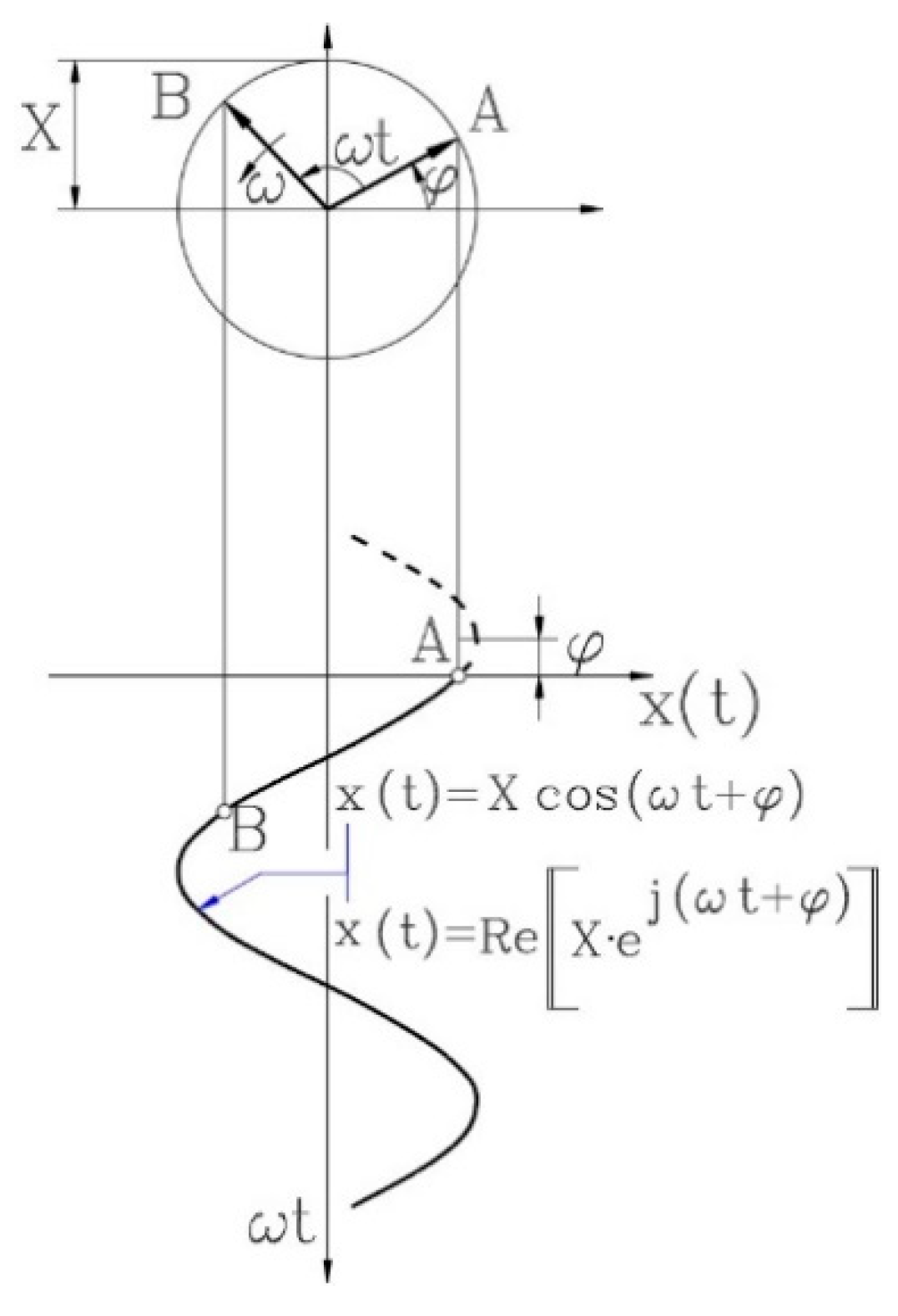
Figure 2.
Phase positions of a 7-phase winding: a) actual positions b) fictitious positions for the projections of a dynamic time phasor with sequence g=3.
Figure 2.
Phase positions of a 7-phase winding: a) actual positions b) fictitious positions for the projections of a dynamic time phasor with sequence g=3.
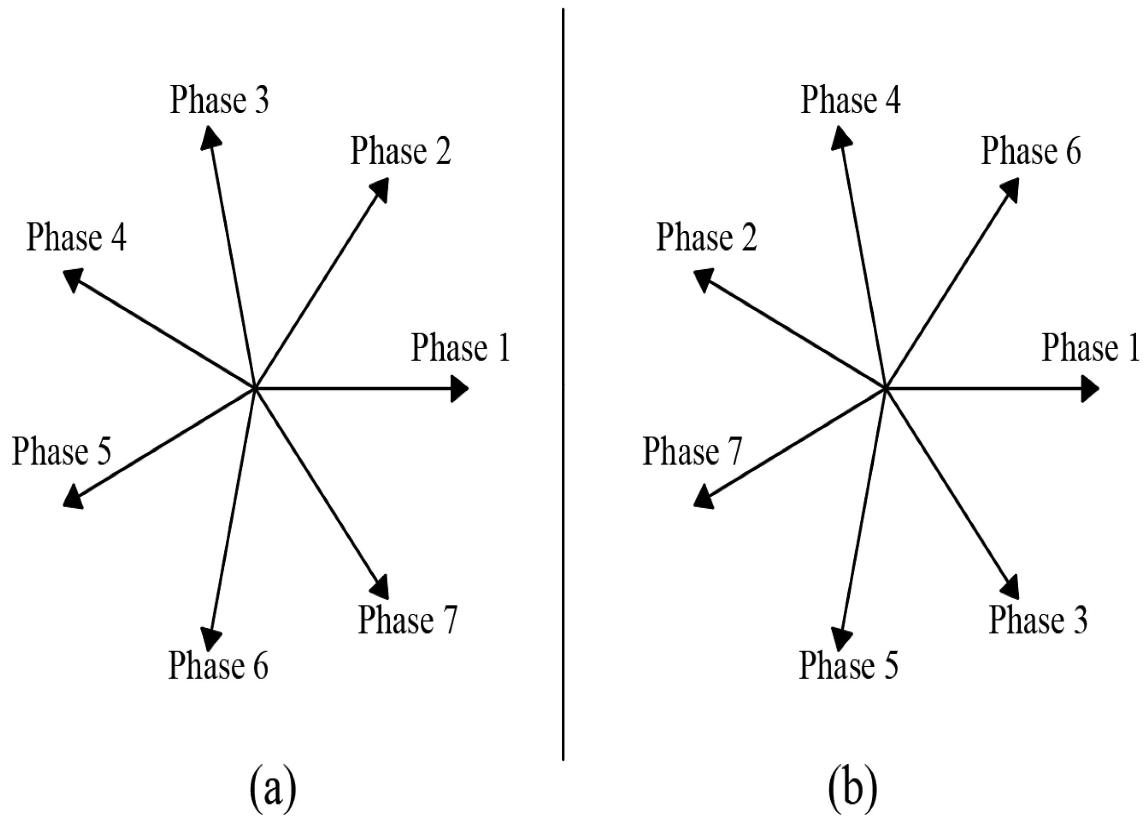
Figure 3.
Flux linking an arbitrary stator coil of a salient pole machine.
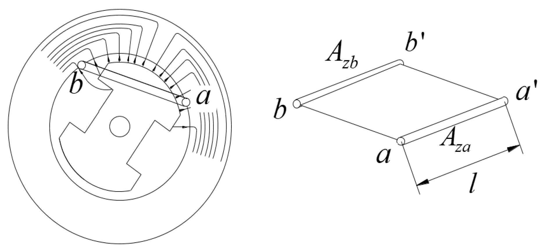
Figure 4.
Space wave of five pole pairs in the machine domain (left) and its corresponding space phasor in the phasorial domain (right).
Figure 4.
Space wave of five pole pairs in the machine domain (left) and its corresponding space phasor in the phasorial domain (right).
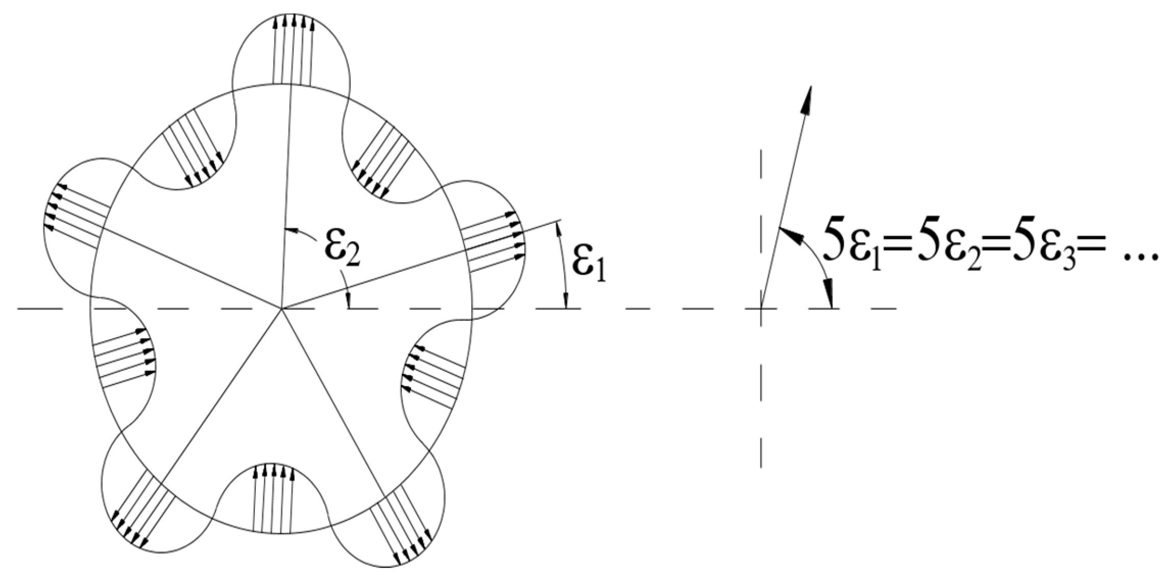
Figure 5.
Geometric interpretation of equation (17).
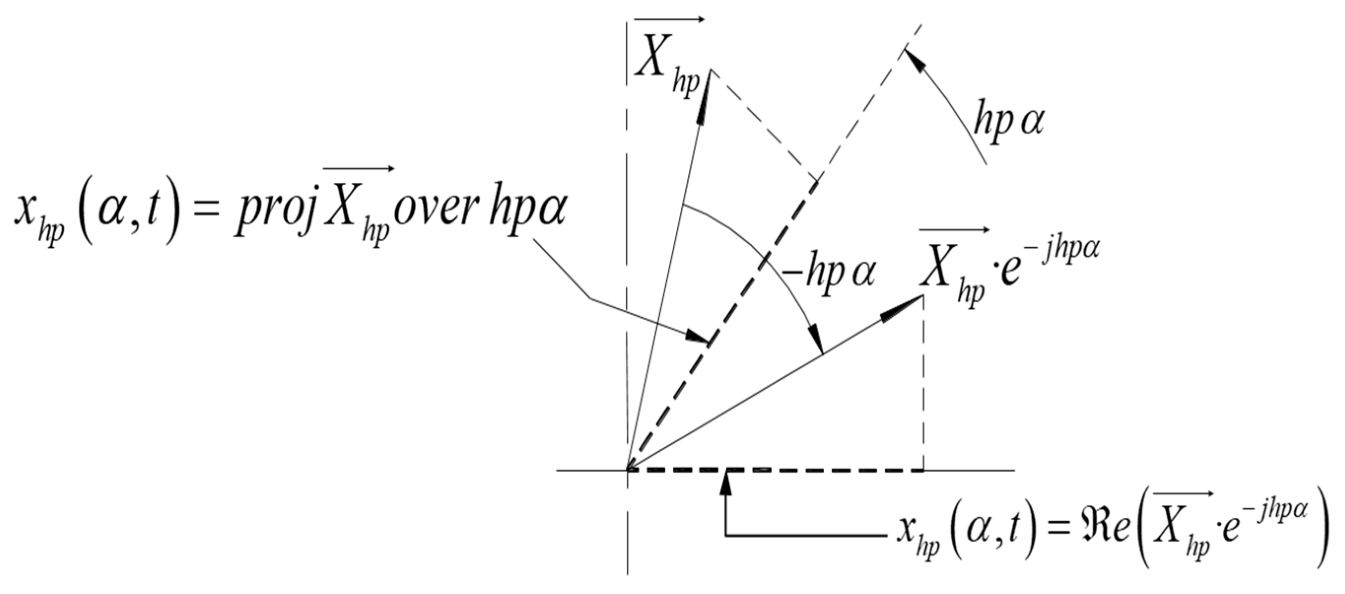
Figure 6.
Direct start-up of a wound induction motor with mstr=mrot=5.
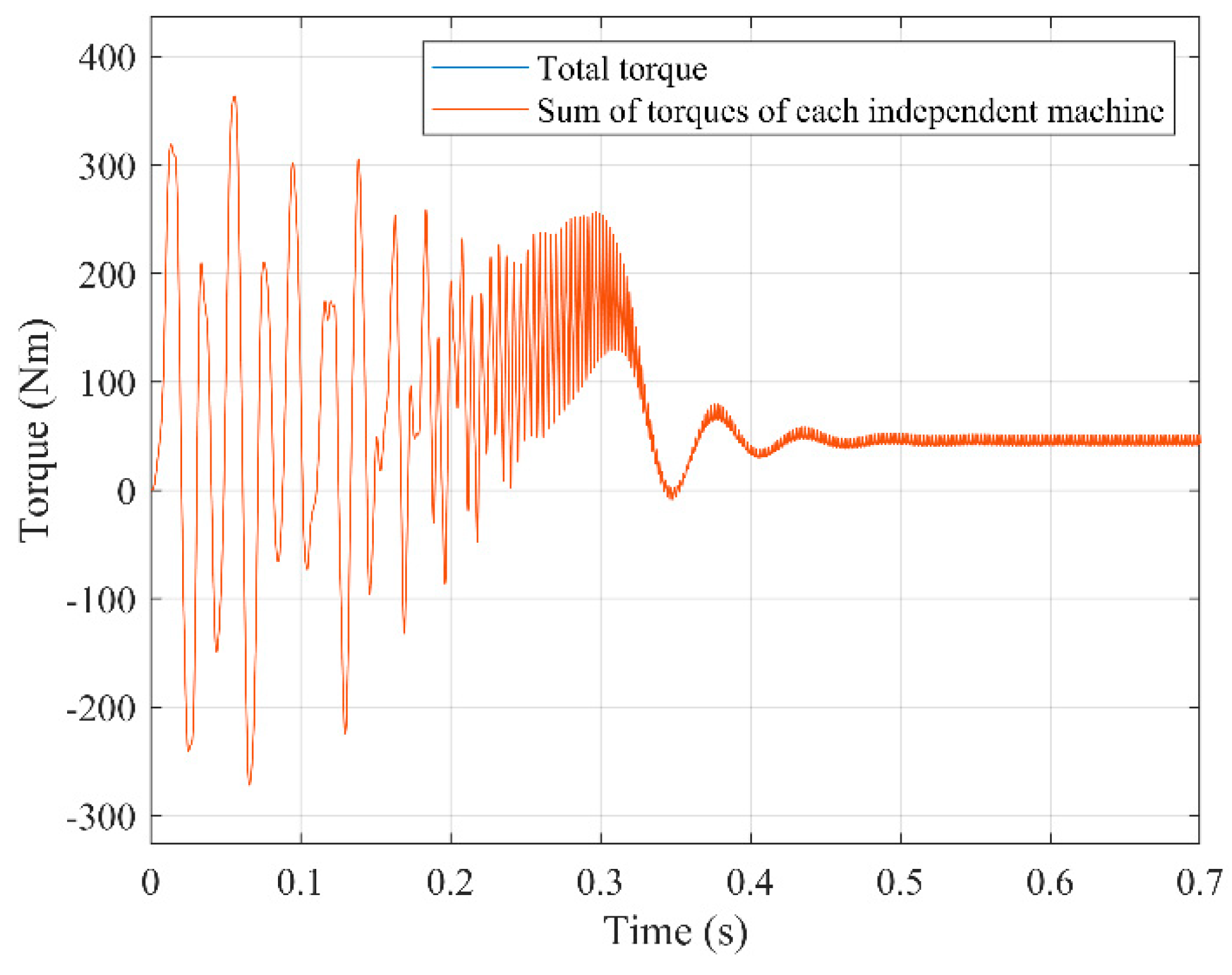
Figure 7.
Direct start-up of a wound induction motor with mstr=5≠mrot=7.
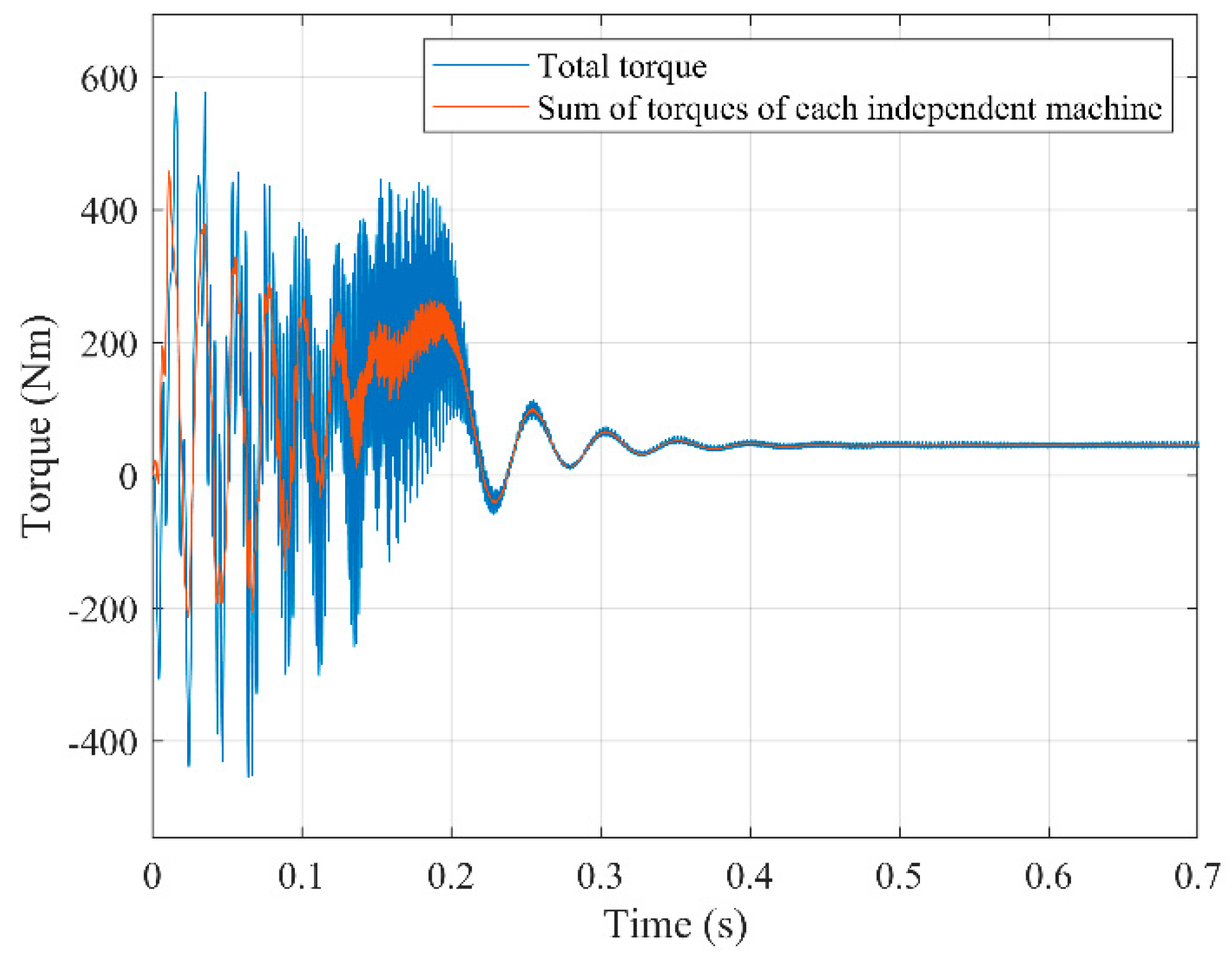
Figure 8.
Direct start-up of a squirrel-cage motor mstr=mrot=7.
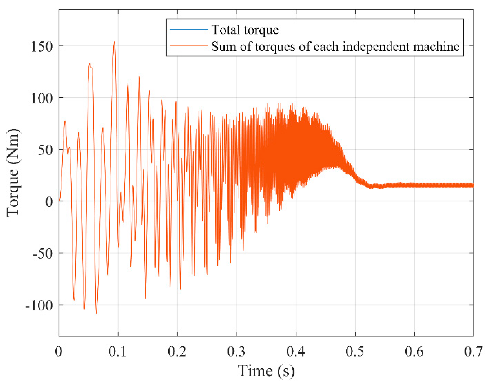
Figure 9.
Direct start-up of a squirrel-cage motor mstr=7≠mrot= 11.
Disclaimer/Publisher’s Note: The statements, opinions and data contained in all publications are solely those of the individual author(s) and contributor(s) and not of MDPI and/or the editor(s). MDPI and/or the editor(s) disclaim responsibility for any injury to people or property resulting from any ideas, methods, instructions or products referred to in the content. |
© 2024 by the authors. Licensee MDPI, Basel, Switzerland. This article is an open access article distributed under the terms and conditions of the Creative Commons Attribution (CC BY) license (http://creativecommons.org/licenses/by/4.0/).
Copyright: This open access article is published under a Creative Commons CC BY 4.0 license, which permit the free download, distribution, and reuse, provided that the author and preprint are cited in any reuse.


