Preprint
Article

This version is not peer-reviewed.

Low-Complexity Model Predictive Control for Series-Winding PMSM with Extended Voltage Vectors

A peer-reviewed article of this preprint also exists.

Submitted:

20 November 2024

Posted:

25 November 2024

You are already at the latest version

Abstract

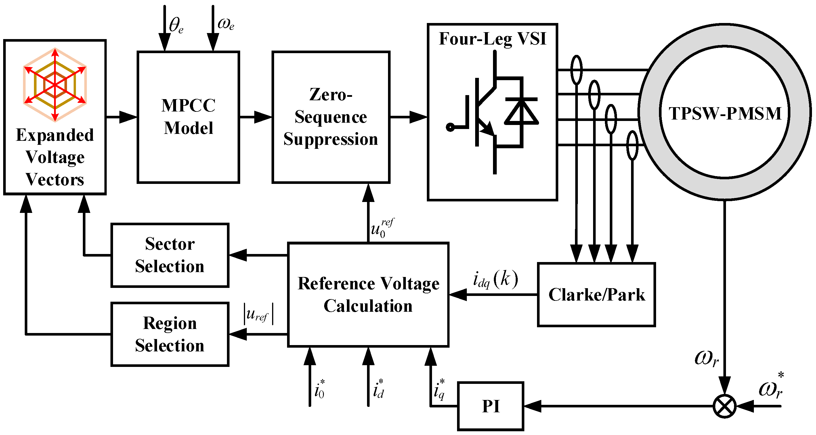
A low-complexity model predictive current control (MPCC) strategy based on extended voltage vectors is proposed to improve computational efficiency and steady-state performance for three-phase series-winding permanent magnet synchronous motors (TPSW-PMSM). This method delivers excellent steady-state performance while substantially reducing the computational burden compared to conventional MPCC. First, a simplified sector selection method is employed to preselect the sector in which the reference voltage vector resides. Next, the reference voltage vector is used to filter out redundant candidate voltage vectors, thereby reducing computation and ensuring real-time control capabilities. Basic active voltage vectors are segmented and recombined according to their magnitudes, without complex duty cycle calculations to further streamline processing. To mitigate the impact of zero-sequence current, zero-sequence current suppression is employed for effective compensation within the control system. This strategy’s combination of reduced computational complexity, reliable steady-state performance, and real-time control establishes it as an efficient solution for TPSW-PMSM systems. Simulation results validate the effectiveness of the proposed method.

Keywords: 
;  ;  ;  

1. Introduction

Due to their simple structure, high power density, and high efficiency, Permanent Magnet Synchronous Motors (PMSMs) are widely used in many industrial applications [1]. These features make PMSMs ideal for electric vehicles (EVs), industrial production and wind power generation, where energy efficiency and reliable performance are crucial [2,3,4,5]. However, traditional star-connected motor drive systems often face limitations in DC voltage utilization, typically achieving only about 57.7%. To address this limitation, extensive research has been conducted on open-end winding motor drive systems. This topology has proven effective in significantly improving DC voltage utilization, enabling more efficient energy use in electric drive systems [6]. Beyond increased voltage utilization, open-end winding motor configurations offer substantial benefits in terms of fault tolerance, making them robust solutions for critical applications such as electric transportation [7]. The ability to operate under fault conditions without significant performance degradation enhances the reliability and safety of electric vehicles, electric buses, and other transport systems, which are expected to maintain continuous operation even under challenging conditions [8]. This combination of higher voltage efficiency and improved fault-tolerant control capability has propelled research into advanced control strategies for open-winding PMSM systems to harness their full potential in practical applications [9]. The introduction of open-end winding topology, while significantly enhancing performance, also increases the number of power electronic components, thereby greatly raising system costs. Consequently, series-winding motor drive topologies have emerged as a solution, striking a balance between cost efficiency and performance [10,11]. Compared to open-end winding motor drives, series winding motor drives achieve the same DC voltage utilization. Additionally, this topology only adds a single bridge arm compared to traditional motor drives.
However, in open-winding and series-winding motor drives, the neutral point of the motor is left open, which results in the formation of a zero-sequence subspace. The zero-sequence current within this subspace significantly increases the total harmonic distortion (THD) of the current as well as torque ripple [12,13]. Therefore, to improve the performance of the control system, the zero-sequence current must be suppressed. Many researchers have conducted studies on suppressing zero-sequence current, particularly in relation to open-winding or series-winding motor drives. In Ref.[14], a zero-sequence current suppression method for open-winding motor drive systems is proposed, employing feedforward voltage compensation and a resonant controller to effectively mitigate zero-sequence current. A novel zero-sequence current suppression control strategy designed for a five-phase open-end winding fault-tolerant drive system is proposed [15], utilizing an unequal distribution of zero voltage vectors for effective suppression. In Ref.[16], a suppression method based on a second-order generalized integrator is introduced, applicable to permanent magnet brushless motor drive systems. Ref.[17] presented a direct torque control strategy for series winding permanent magnet synchronous motors with zero-sequence current suppression capability. This strategy uses closed-loop control to simultaneously regulate electromagnetic torque, stator flux linkage, and zero-sequence current. Based on the above discussion, it can be seen that the active control of zero-sequence current is necessary for zero-sequence current suppression in the TPSW-PMSM drive [18].
Additionally, model predictive control (MPC), as an advanced control method, is introduced in TPSW-PMSM drive systems due to its simplicity and flexibility in handling multiple objectives, such as switching frequency, harmonic current suppression, and common-mode voltage elimination [19]. MPC can be categorized based on the continuity of control inputs into finite control set model predictive control (FCS-MPC) and continuous control set model predictive control (CCS-MPC). Due to the computational limitations of microprocessors, CCS-MPC has not seen widespread use, whereas FCS-MPC is more commonly preferred for practical applications [20,21]. FCS-MPC provides simpler computational realization, making it suitable for systems where fast dynamic response is essential and computational resources are limited [22]. Based on different control objectives, MPC for PMSM can be further divided into model predictive current control (MPCC) [23,24,25], model predictive torque control (MPTC) [26,27], and model predictive speed control (MPSC) [28,29]. The basic principle of traditional MPC involves traversing all possible voltage vectors generated by the converter and selecting the voltage vector that minimizes the cost function as the output. Traditional MPC outputs only one voltage vector per sampling period, which can lead to significant current ripples [30]. To address this issue, duty cycle based MPC [31] was proposed, which allocates time between active and null voltage vectors within one period, effectively improving the quality of the output current. However, duty cycle control does not achieve the optimal voltage vector, as the combination of active and null voltage vectors can only change the magnitude of the basic voltage vector without altering its angle. To address this limitation, multi-vector model predictive control (MV-MPC) [32] was proposed. In this approach, the second vector is not restricted to null vectors but can be selected from all available vectors. Compared to duty ratio model predictive control, MV-MPC significantly improves control performance. It is noteworthy that as the number of secondary voltage vectors increases, the number of voltage vectors that need to be evaluated within one control cycle also rises. This inevitably leads to a greater computational burden, which can affect the real-time performance of the control system.
To this end, a low-complexity model predictive current control with zero-sequence current suppression capability is proposed for the TPSW-PMSM drive system. By subdividing the voltage vectors and pre-combining them, additional virtual voltage vectors are created to improve the system’s steady-state performance. At the same time, to reduce the computational burden caused by the increased number of virtual voltage vectors, a simplified search strategy is introduced. This strategy selects the sector in advance based on the location of the reference voltage vector and eliminates redundant voltage vectors by assessing the magnitude of the reference voltage vector, significantly reducing the computational load. Furthermore, to suppress zero-sequence current, the method of zero-sequence voltage injection is employed.
The paper is organized as follows. In Section 2, the mathematical model of the TPSW-PMSM is introduced, along with the distribution of basic voltage vectors in different subspaces. In Section 3, the simplified sector selection method and the voltage distribution principles are presented, followed by a discussion on how to narrow the range of available voltage vectors. Section 4 describes the method of zero-sequence voltage injection to suppress zero-sequence current and discusses how to allocate the time duration for zero-sequence and non-zero-sequence voltage components. Finally, in Section 5, simulation results are provided to validate the effectiveness of the proposed method.

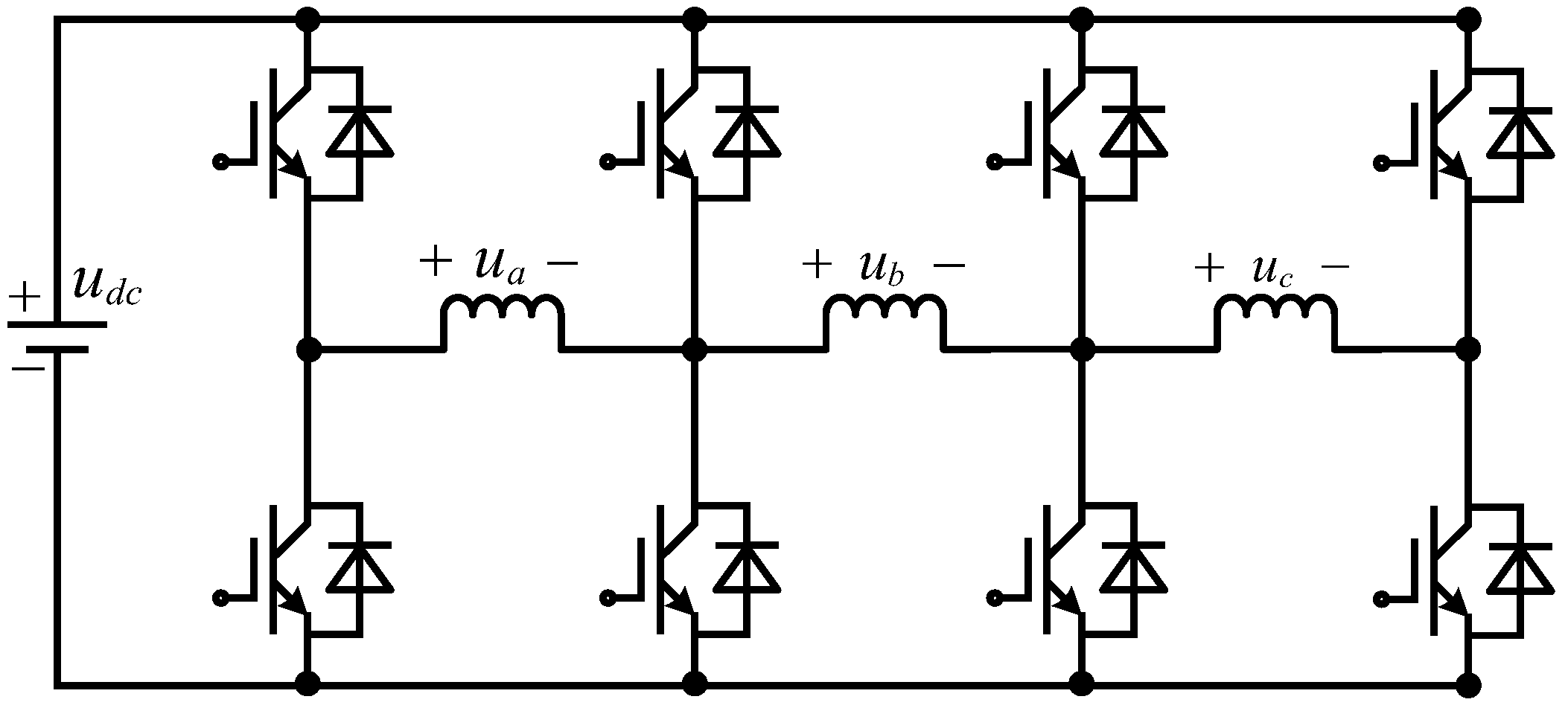
2. Modeling of TPSW-PMSM Drive

2.1. Mathematical Model of the TPSW-PMSM

The topology of the TPSW-PMSM is shown in Figure 1. The three-phase stator windings are connected in series, similar to the structure of an open-winding motor drive. In the TPSW-PMSM, the neutral point is also left open, making the zero-sequence subspace unavoidable.
According to the Clarke and Park transformation, the stator voltage in the d-q-0 coordinate system can be expressed by the voltage equations as follows:
u d u q u 0 = R s i d i q i 0 + L d q o d d t i d i q i 0 + ω e L q i q L d i d + ψ f 3 ψ f 3 sin ( 3 θ e )
In this context, u d , u q , u 0 and i d , i q , i 0 represent the voltage and current in the d q 0 coordinate system, respectively. ψ f denotes the stator flux linkage. ψ f 3 indicates the third harmonic rotor flux linkage. R s represents the stator resistance. θ e stands for the electrical angle of the rotor. The inductance in the d q 0 axis can be expressed as L d q 0 . The torque equation of the TPSW-PMSM can be expressed as follows:
T e = 3 2 n p [ ψ f i q + ( L d L q ) i d i q 6 ψ f 3 sin ( 3 θ e ) i 0 ]

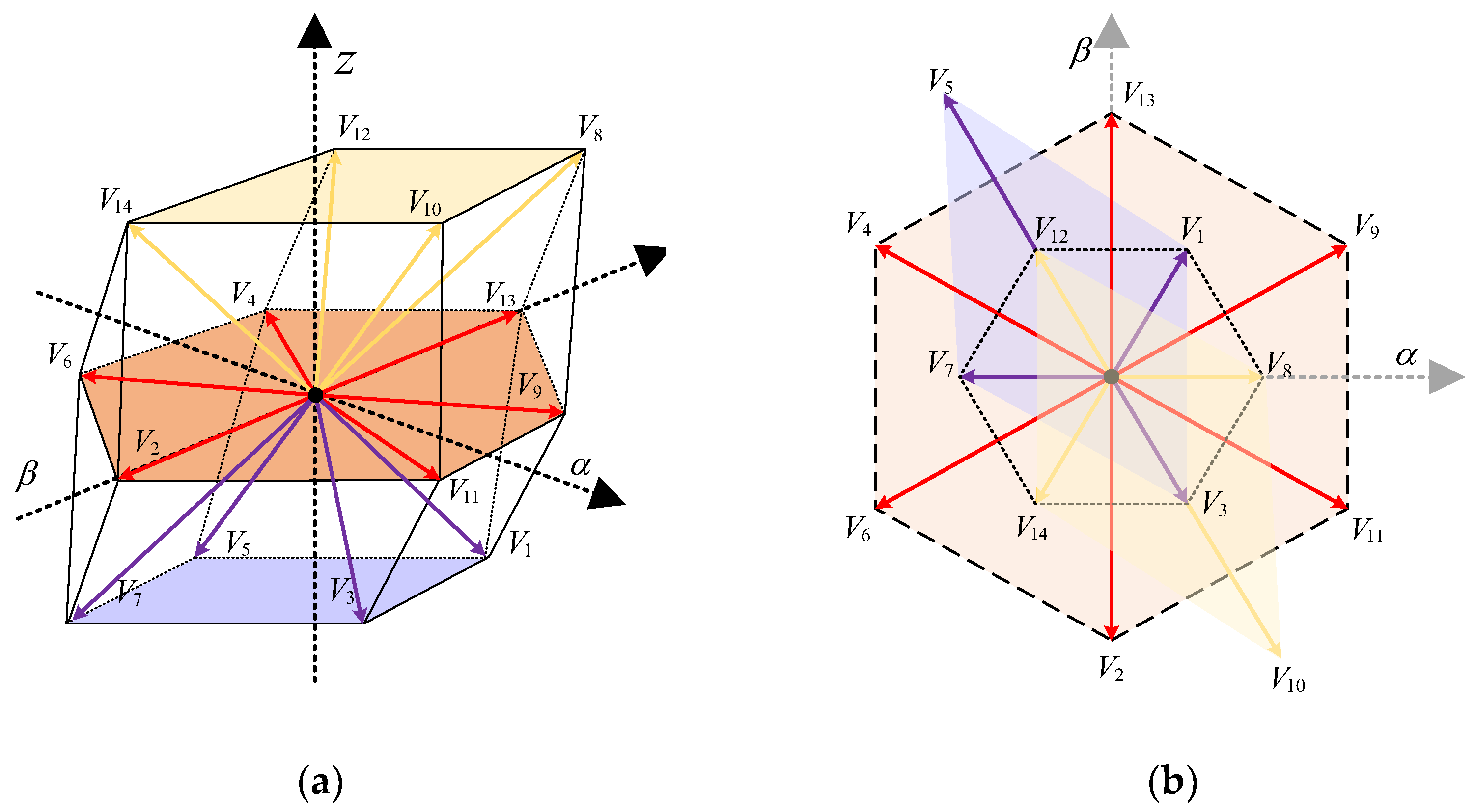
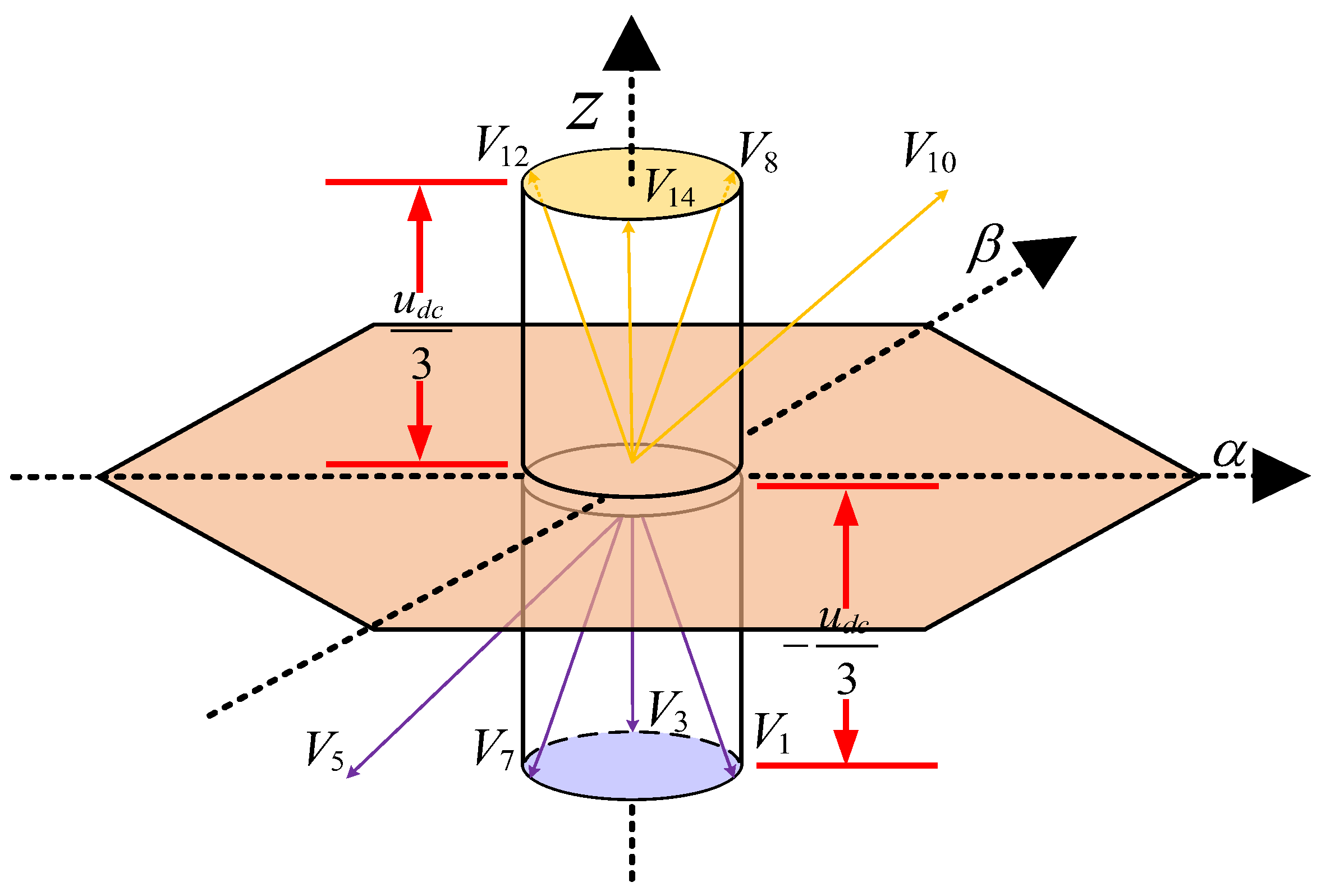
2.2. Voltage Vector Distribution Within the Subspace

Additionally, compared to the conventional Y-connected topology drive, the unique topology of the TPSW-PMSM generates a higher-dimensional zero-sequence subspace, and the number of basic voltage vectors increases. The three-dimensional distribution of the basic voltage vectors is shown in Figure 2(a), while the two-dimensional distribution is depicted in Figure 2(b). Among these, V 0 and V 15 are two null voltage vectors that are not shown in the figures.
For ease of subsequent analysis, all basic voltage vector components on the α β z axis and their corresponding switching states are listed in Table 1. It can be observed that in the series-winding drive, in addition to the voltage vectors in the α β plane, there are also voltage vectors in the z-axis direction. As the number of bridge arms increases, the number of voltage vectors rises from the original 2 3 to 2 4 . Since the selection of the optimal voltage vector in MPC follows an exhaustive search principle, the increase in the number of voltage vectors undoubtedly results in a higher computational burden. Among the 16 basic voltage vectors, V 0 and V 15 are null vectors that only change the magnitude of the synthesized voltage vector without altering the angle. V 2 , 4 , 6 , 9 , 11 , 13 are effective vectors without zero-sequence components. V 8 , 10 , 12 , 14 are voltage vectors with positive zero-sequence components, with the amplitude of the zero-sequence component being u d c / 3. V 1 , 3 , 5 , 7 are voltage vectors with negative zero-sequence components, where the amplitude of the zero-sequence component is u d c / 3.

3. Improved MPCC for TPSW-PMSM

This section introduces the improved MPCC for TPSW-PMSM, beginning with an explanation of its basic principles and presenting the fundamental mathematical model. Subsequently, the shortcomings of the traditional MPCC are discussed, leading to the introduction of the improved method proposed in this paper.

3.1. Basic Principles of MPCC

First, the discrete mathematical model of the TPSW-PMSM is defined, which is the key to implementing MPCC, as shown in (3)
i d ( k + 1 ) i q ( k + 1 ) i 0 ( k + 1 ) = 1 T s R s L d ω e T s L q L d 0 ω e T s L q L q 1 T s R s L q 0 0 0 1 T s R s L 0 i d ( k ) i q ( k ) i 0 ( k ) + T s u d ( k ) / L d u q ( k ) / L q u 0 ( k ) / L 0 + ω e ( k ) 0 T s ψ f / L q 3 ψ f 3 sin ( 3 θ e ) T s / L 0
k represents the k th step, while k + 1 denotes the predicted value at the next time step. T s is the sampling period. The basic principle of MPCC is to utilize the controlled model described above, iteratively traversing all basic voltage vectors during each sampling period to predict future system behavior. The predicted current values are then substituted into the cost function (4) to evaluate errors.
g = [ i d r e f i d ( k + 1 ) ] 2 + [ i q r e f i q ( k + 1 ) ] 2 + δ [ i 0 r e f + i 0 ( k + 1 ) ] 2
In (4), i d r e f , i q r e f , and i 0 r e f represent the reference current values. Since the error between i 0 and its reference value is smaller compared to the errors between i d , q and their respective reference values, a weighting coefficient δ is introduced to prioritize i 0 in the control system. MPCC model selects the voltage vector that minimizes the cost function as the output and applies it within the control period. It is worth noting that due to inherent time delays in system computation and execution, discrepancies may arise between the control signals and system response. To effectively address this issue, a delay compensation component is integrated into the MPCC.
As mentioned in the previous section, the introduction of the zero-sequence subspace generates more voltage vectors, which results in a greater computational burden. This increased complexity can have negative impacts in scenarios where high dynamic performance is required, making the reduction of computational complexity an urgent issue to address. Additionally, in traditional MPCC, only one voltage vector is output per sampling period, which can lead to significant discrepancies between the optimal voltage vector and the desired voltage vector, thereby causing large steady-state errors.

3.2. Basic Principles of Proposed MPCC

As mentioned above, this paper primarily focuses on two aspects of traditional MPCC: computational complexity and steady-state performance. The following sections introduce the methods adopted in this paper for addressing these issues.

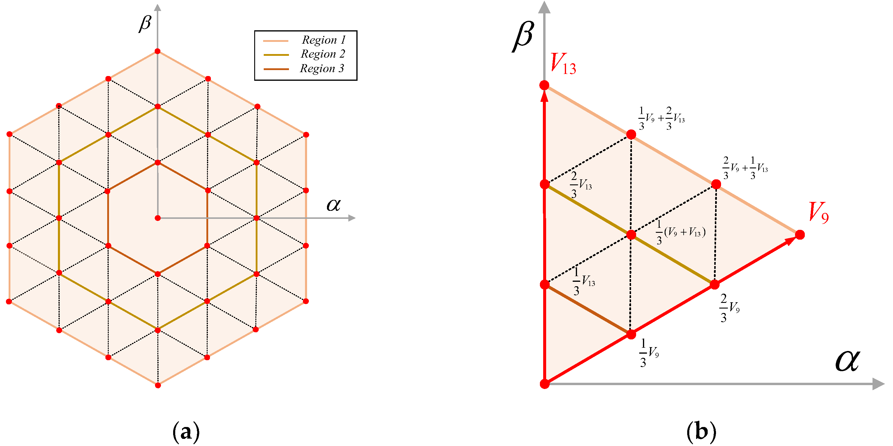
3.2.1. Expanded Voltage Vectors

In traditional MPCC, only one voltage vector is output per sampling period, which inevitably results in significant current and torque fluctuations. To address this issue, a Duty Cycle Control (DCC) method is proposed, combining effective voltage vectors ( V 2 , V 4 , V 6 , V 9 , V 11 , V 13 ) and null voltage vectors ( V 0 , V 15 ). This method adjusts the amplitude of the effective voltage vectors to make the final output voltage vector more closely approximate the reference voltage vector. However, since this approach only modifies the amplitude of the voltage vectors, the improvement in steady-state performance is quite limited. Subsequently, a dual-vector model predictive control method (DVMPCC) is introduced, where the selection of the second vector is no longer restricted to null voltage vectors but includes all voltage vectors. This significantly enhances the steady-state performance of the control system. The trade-off, however, is the increased computational burden due to the complex voltage vector traversal and time allocation calculations.
To this end, this section proposes a voltage vector refinement strategy. To address the issue of limited voltage vectors in the α β -plane, the six original voltage vectors are first divided into three regions based on their magnitudes, as illustrated geometrically in Figure 3(a). Compared to traditional MPCC, this approach provides more selectable voltage vectors, resulting in improved steady-state performance. Unlike DCC-MPCC and DV-MPCC, this method eliminates the step of calculating time allocation, thereby reducing computational complexity; however, it requires pre-combination of virtual voltage vectors. An example illustrating the pre-combination principle for any given region is shown in Figure 3(b). After the voltage vector subdivision, the 8 effective voltage vectors on the plane expand to 38 vectors. Whether considered from the perspective of vector angles or magnitudes, the refined set of 38 voltage vectors offers a more comprehensive coverage. However, it is important to note that the number of voltage vectors that need to be traversed per cycle increases approximately sixfold. Therefore, it is necessary to pre-filter certain voltage vectors based on the position and magnitude of the reference voltage vector.

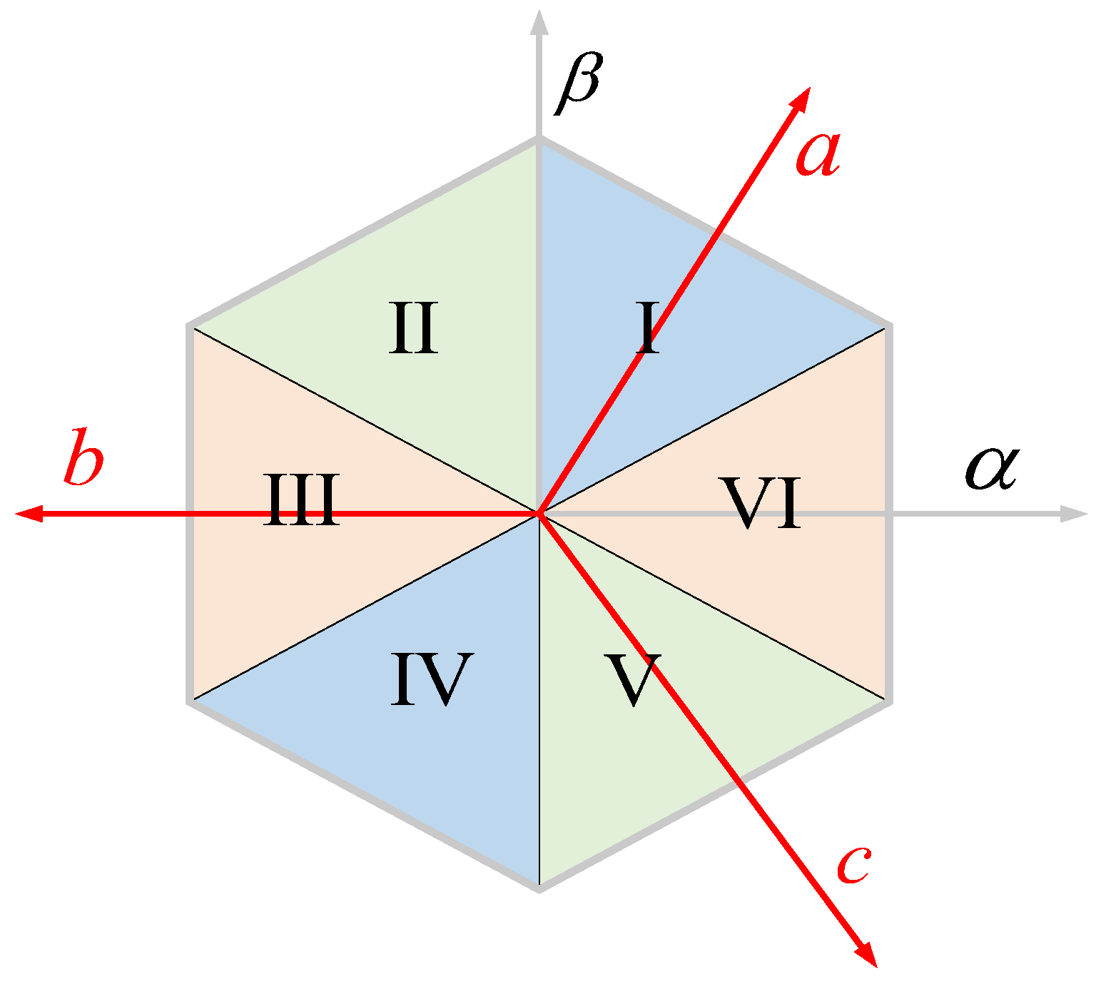
3.2.2. Simplified Voltage Vector Selection

In traditional MPCC, the general method for determining the sector in which the reference voltage lies involves transforming the reference voltage vector obtained from (5) using the inverse Park transformation (6) to obtain its components on the α β -axis. By dividing these components and calculating the arctangent (7), the angle θ relative to α axis is determined, which is then used to identify the sector. Although many MCU manufacturers provide computational libraries that include arctangent functions, these calculations are time-consuming and affect the response speed of the current loop.
u d r e f = R s i d ( k ) + L d [ i d r e f i d ( k ) ] T s ω e ( k ) L q i q ( k ) u q r e f = R s i q ( k ) + L d [ i q r e f i q ( k ) ] T s ω e ( k ) [ L d i d ( k ) + ψ f ]
u α r e f u β r e f = cos θ e sin θ e sin θ e cos θ e u d r e f u q r e f
θ = arctan ( u α r e f u β r e f )
Figure 4 illustrates the simplified sector selection principle. First, the ( a , b , c ) three-phase reference frame is established, with the three axes separated by 120 degrees and perpendicular to the boundaries of sectors I, III and V respectively. Therefore, the components u a u b u c and u α u β have a clear geometric relationship, as shown in (8). The sector of the reference voltage can be determined based on the polarity of the voltage in the ( a , b , c ) coordinate system, resulting in δ n = 1 u x > 0 δ n = 0 u x 0 .
The correspondence between the signs of the components and the sectors is shown in Table 2.
u a u b u c = 1 2 3 2 1 2 3 2 u α u β
After determining the sector, the effective voltage vectors at the boundaries of the sector can be identified. To further filter the voltage vectors, a voltage selection method based on the magnitude of the reference voltage vector is proposed. The region can be determined by evaluating the magnitude of the reference voltage vector, as shown in (9). The calculation formula for the reference voltage magnitude is: u r e f = ( u d r e f ) 2 + ( u q r e f ) 2
Region   1 ,   0 < u r e f 2 3 9 u d c Region   2 ,   2 3 9 u d c < u r e f 4 3 9 u d c Region   3 ,   4 3 9 u d c < u r e f 2 3 9 u d c
By combining the simplified sector determination principle and the magnitude judgment principle, the number of voltage vectors that need to be evaluated within one cycle is significantly reduced—from the original 38 voltage vectors to a maximum of 4. This approach greatly balances steady-state performance with computational complexity.

4. Zero-Sequence Current Suppression Strategy

As mentioned earlier, due to the topology of the TPSW-PMSM drive, the emergence of a zero-sequence subspace is inevitable. Section 3 discussed the voltage vector optimization strategy in the α β plane, and this section focuses on suppressing the zero-sequence component. First, the vectors within the zero-sequence subspace are analyzed, defining the intersection of the α β plane and the z-axis as the zero point of the z-axis, with the positive direction upward and the negative direction downward. The eight voltage vectors within the zero-sequence subspace can be categorized into vectors with positive zero-sequence components ( V 8 , V 10 , V 12 , V 14 ), with z-axis components u d c / 3 , and vectors with negative zero-sequence components( V 1 , V 3 , V 5 , V 7 ), with z-axis components u d c / 3 . Notably, each of the positive and negative sets includes three fully symmetrical voltage vectors ( V 8 , V 12 , V 14 ) and ( V 1 , V 3 , V 7 ), which implies that their resultant voltage vector can precisely form a complete zero-sequence vector. The set details are shown in Figure 5.
It can be observed that, due to the symmetry among the three vectors, their resultant vector has no α β components and can be modulated independently. Referring to Table 1, to achieve the forward synthesized voltage vector u z p , the conduction times of the four bridge arms are respectively defined as follows:
( L 1 , L 2 , L 3 , L 4 ) = k * ( 1 , 1 2 , 1 3 , 0 ) * T s , ( 0 < k 1 )
Similarly, to achieve the negative synthesized voltage vector u z n , the conduction times of the four bridge arms are defined as follows.
( L 1 , L 2 , L 3 , L 4 ) = k * ( 0 , 1 3 , 1 2 , 1 ) * T s , ( 0 < k 1 s )
The coefficients k are obtained from (10).
u 0 r e f = R s i 0 ( k ) + L 0 [ i 0 r e f i 0 ( k ) ] T s 3 ω e ( k ) ψ f 3 sin ( 3 θ e ) k = ( u 0 r e f ) 2 u d c / 3
Combining the voltage output strategy on the α β plane mentioned in the section 3, the vector modulation in three-dimensional space is completed. However, it is necessary to consider the possibility of over-modulation when zero-sequence voltage is included. If the operating time of any switching signal for the final output voltage vector exceeds T s , the inverter cannot output that voltage vector, potentially leading to poorer performance. Therefore, it is important to determine the priority between the voltage vector on the α β plane and the zero-sequence voltage vector. From the perspective of coverage, the area that the α β plane can cover is evidently broader. Thus, when over-modulation occurs, the coefficient k needs to be reconsidered, as shown in(11), where T α β represents the conduction time of the bridge arm corresponding to the voltage vector within the α β plane. Figure 6 shows the control block diagram of the proposed method. First, the reference voltage value is calculated based on the current reference and the actual current values. Then, the Region is selected according to the magnitude of the reference voltage, and the sector is selected based on the position of the reference voltage in the coordinate system. Further, the range of candidate voltage vectors is reduced according to two selection principles. Finally, zero-sequence current suppression is performed.
k = 1 max ( T α β T s ) , k + max ( T α β T s ) > 1 k , k + max ( T α β T s ) 1

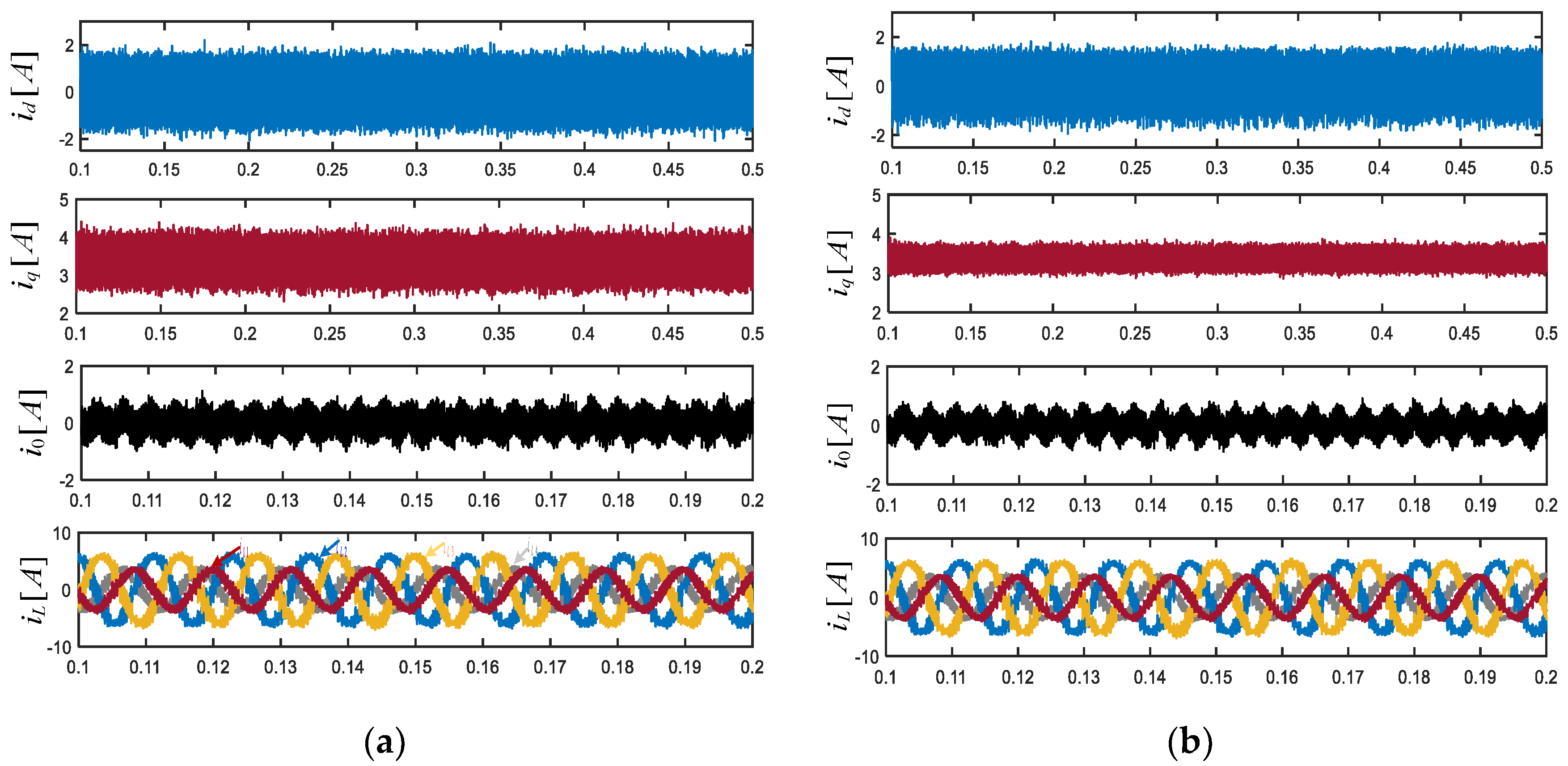
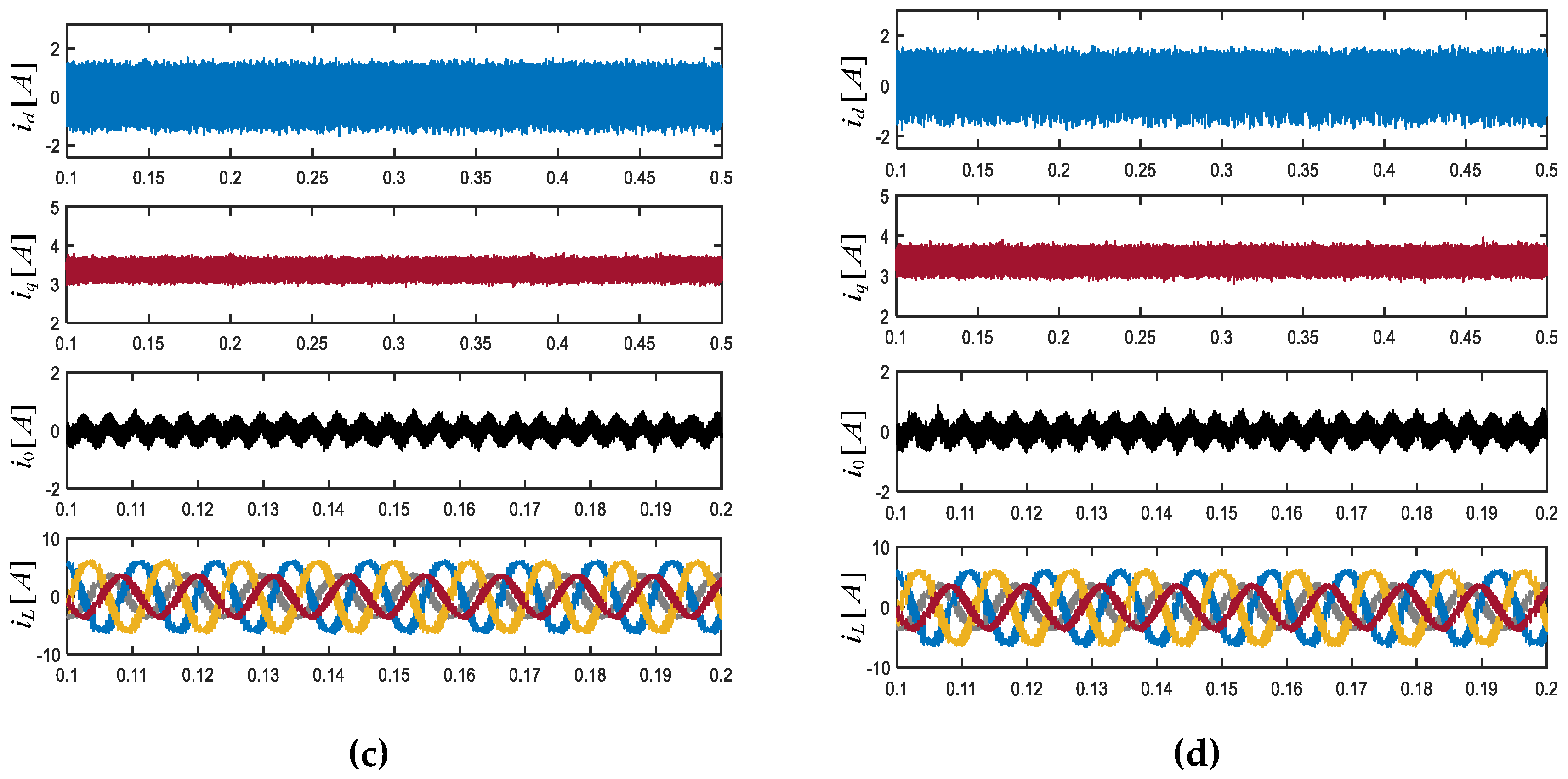
5. Simulation Validation

To verify the effectiveness of the proposed method, a simulation model for TPSW-PMSM was built in MATLAB/Simulink, including the traditional MPCC simulation model, the DCC-MPCC simulation model, the DV-MPCC simulation model, and the MPCC simulation model proposed in this paper. Comparative simulation experiments were conducted. Table 3 presents the various parameters used in the simulation models. The traditional Y-connected motor opens the neutral point and connects the three-phase windings of the motor stator in series to form the SW-PMSM.

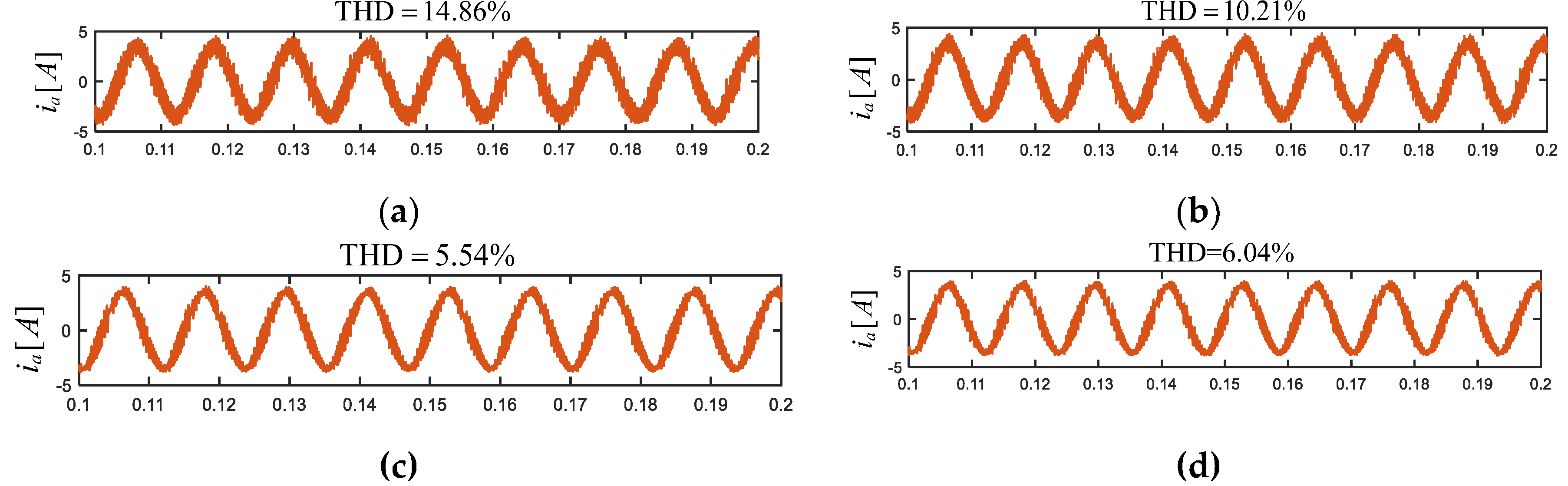
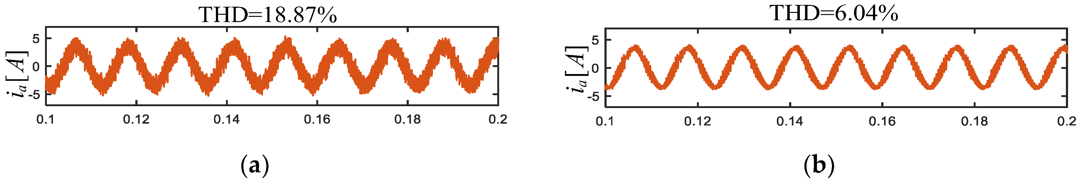
5.1. Steady-State Performance and Computational Complexity Evaluation

To fully demonstrate the improvement in steady-state performance achieved by this method, comparative static performance experiments were conducted under different operating conditions. First, the waveforms of the three-phase currents, their Total Harmonic Distortion (THD), and the zero-sequence currents under different control methods at the same rotational speed are presented, as shown in Figure 7 and Figure 8.
Figure 7 shows the waveforms of dq-axis currents and zero-sequence current under operating conditions of 1000 r/min and 2 N.m for four different methods. Figure 8 shows the THD corresponding to the four methods. It is evident that, due to the inclusion of the null voltage vector, the DCC-MPCC method demonstrates significant improvements in static performance compared to the traditional MPCC. Similarly, because of the expanded range of voltage vector selection, the DV-MPCC method shows further improvements in static performance over DCC-MPCC. The proposed method outperforms both the traditional MPCC and DCC-MPCC in terms of static performance, as it extends the voltage vector in various directions. Additionally, compared to the computationally intensive DV-MPCC, the proposed method still shows commendable static performance. Notably, the proposed method significantly reduces computational complexity compared to DV-MPCC by simplifying sector selection and eliminating the need for time allocation calculations. Therefore, this method provides significant improvements in both static performance and computational efficiency. Figure 9 presents the THD for proposed MPCC with and without the zero-sequence current suppression strategy, visually validating the effectiveness of the zero-sequence current suppression strategy.

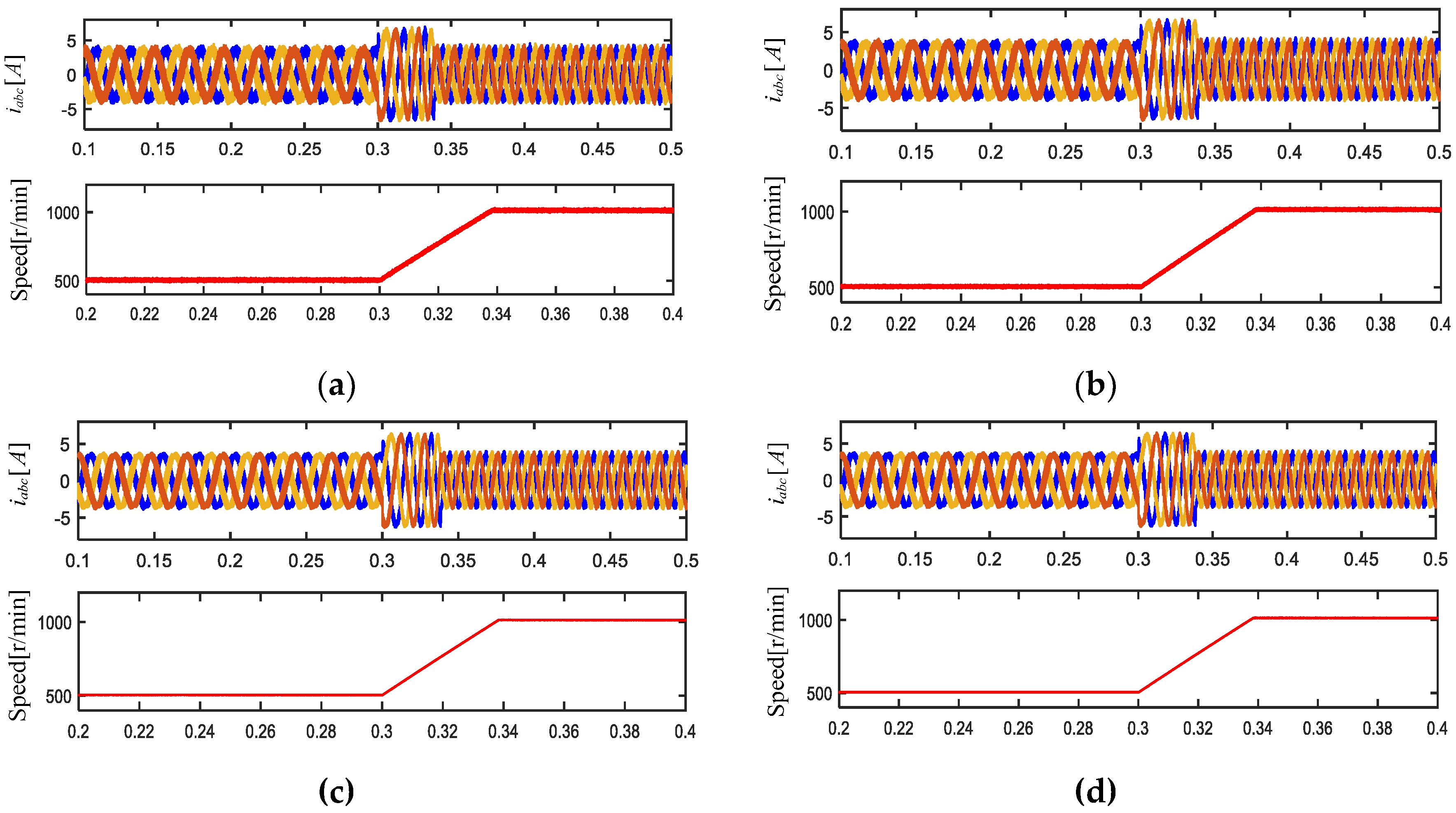
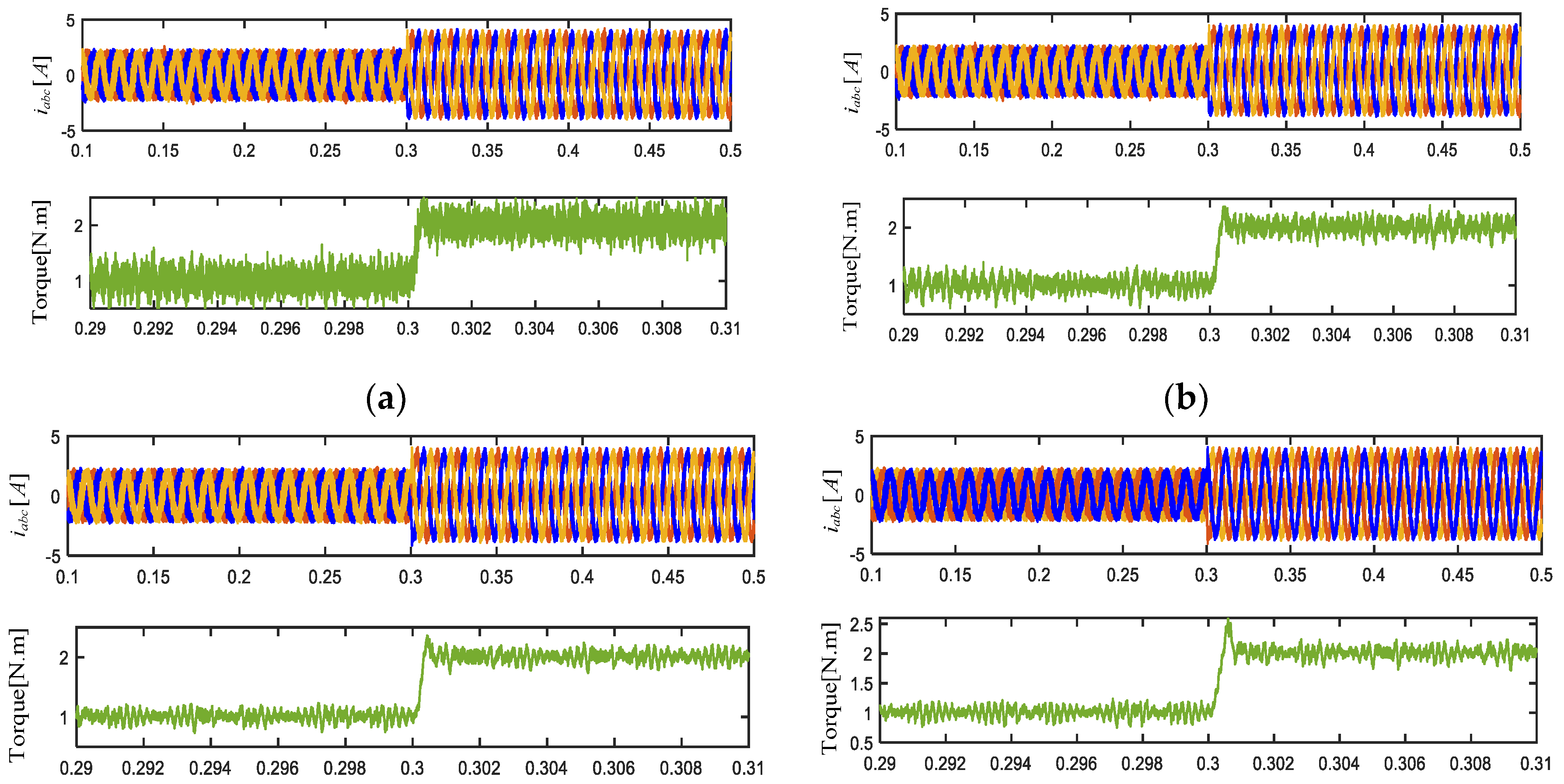
5.2. Dynamic Performance Evaluation

In addition to the steady-state performance evaluation, dynamic performance validation was also conducted. In Figure 10, with torque held constant at 2 N·m, the speed changes from 500 r/min to 1000 r/min. It can be observed that all four methods respond quickly to the speed change, reaching the reference speed within approximately 30 ms. In Figure 11, with the speed maintained at 1000 r/min, the torque is increased from 1 N.m to 2 N.m. Similarly, all four methods exhibit reasonable dynamic performance, with the proposed method showing superior torque ripple suppression compared to traditional methods, demonstrating its advantages.

6. Conclusions

This paper presents an advanced control method for the TPSW-PMSM drive that strikes an optimal balance between computational complexity and static performance while effectively suppressing zero-sequence current to minimize current and torque fluctuations. The proposed method’s feasibility in reducing computational load and enhancing static performance is confirmed through simulation studies. The main contributions of this approach include:
(1) The paper first addresses the drawbacks of conventional MPCC, which outputs only one voltage vector per cycle, leading to significant errors. To resolve this, the method subdivides basic voltage vectors by their magnitudes and synthesizes additional vectors with greater flexibility in both angle and magnitude. This increases the number of candidate voltage vectors on the 2D plane from 8 to 38, substantially enhancing static performance. Compared to MV-MPCC, this method eliminates the need for calculating the distribution of dwell time, further reducing the computational burden.
(2) Given the potential computational challenges posed by the increased number of voltage vectors, a simplified sector selection scheme and a region selection principle are introduced. These strategies reduce the number of candidate voltage vectors from 38 to a maximum of 4, significantly lowering the computational load.
(3) To mitigate the adverse effects of zero-sequence components on control performance, the paper employs a three-vector synthesis method, effectively suppressing zero-sequence current and greatly enhancing overall control performance.

Funding

This research was funded by the National Key Research and Development Program 2023YFF0719100 and National Natural Science Foundation of China 52477063.

References

  1. C. Liu, “Emerging Electric Machines and Drives — An Overview,” in IEEE Transactions on Energy Conversion, vol. 33, no. 4, pp. 2270-2280, Dec. 2018.
  2. Wang, X.; Wang, D.; Peng, C.; Wang, B.; Wang, X. Torsional Vibration Analysis and Suppression of Interior Permanent Magnet Synchronous Motor With Staggered Segmented Rotor for Electric Vehicles. IEEE Trans. Transp. Electrification 2023, 10, 6285–6294. [Google Scholar] [CrossRef]
  3. Lemma, B.D.; Pradabane, S. An Optimized Alternative Fixed Switching 12-Sector Space Vector Pulse Width Modulation Control of Open-End Winding PMSM Drive. IEEE Access 2023, 11, 55169–55177. [Google Scholar] [CrossRef]
  4. Wang, X.; Lin, X.; Huang, Q.; Xie, W. An Improved Parallel Predictive Torque Control for Permanent Magnet Synchronous Motor. IEEE Access 2023, 11, 32496–32507. [Google Scholar] [CrossRef]
  5. Bao, G.; Qi, W.; He, T. Direct Torque Control of PMSM with Modified Finite Set Model Predictive Control. Energies 2020, 13, 234. [Google Scholar] [CrossRef]
  6. Sun, X.; Liu, Z.; Li, A.; Wang, Z.; Jiang, D.; Qu, R. Self-Adaptive Fault-Tolerant Control of Three-Phase Series-End Winding Motor Drive. IEEE Trans. Power Electron. 2022, 37, 10939–10950. [Google Scholar] [CrossRef]
  7. Zuo, Y.; Zhu, X.; Si, X.; Lee, C.H.T. Fault-Tolerant Control for Multiple Open-Leg Faults in Open-End Winding Permanent Magnet Synchronous Motor System Based on Winding Reconnection. IEEE Trans. Power Electron. 2020, 36, 6068–6078. [Google Scholar] [CrossRef]
  8. Bao, Y.; Zhang, X.; Zhao, J.; Li, B.; Xu, C. Research of Fault-Tolerant Control Strategy for Open-End Winding PMSM Under Open-Phase Fault. 2023 IEEE PELS Students and Young Professionals Symposium (SYPS). LOCATION OF CONFERENCE, ChinaDATE OF CONFERENCE; pp. 1–5.
  9. Oto, Y.; Noguchi, T.; Fauziah, M.B. Experimental Verification of Fault Tolerant Operation Focusing on DC-Bus Battery Failure in Dual Inverter Motor Drive. World Electr. Veh. J. 2019, 10, 65. [Google Scholar] [CrossRef]
  10. Li, A.; Jiang, D.; Liu, Z.; Sun, X. Generalized PWM Method for Series-End Winding Motor Drive. IEEE Trans. Power Electron. 2020, 36, 4452–4462. [Google Scholar] [CrossRef]
  11. Dong, Z.; Liu, C.; Song, Z.; Liu, S. Suppression of Dual-Harmonic Components for Five-Phase Series-Winding PMSM. IEEE Trans. Transp. Electrification 2021, 8, 121–134. [Google Scholar] [CrossRef]
  12. Hu, W.; Ruan, C.; Nian, H.; Sun, D. Zero-Sequence Current Suppression Strategy With Common-Mode Voltage Control for Open-End Winding PMSM Drives With Common DC Bus. IEEE Trans. Ind. Electron. 2020, 68, 4691–4702. [Google Scholar] [CrossRef]
  13. Song, Z.; Dong, Z.; Wang, W.; Liu, S.; Liu, C. A Novel Modulation Strategy for Asymmetrical Six-Phase Series-Winding PMSM Based on Predictive Controller. IEEE Trans. Ind. Electron. 2022, 70, 5592–5603. [Google Scholar] [CrossRef]
  14. Kubo, H.; Yamamoto, Y.; Kondo, T.; Rajashekara, K.; Zhu, B. Zero-sequence current suppression for open-end winding induction motor drive with resonant controller. 2016 IEEE Applied Power Electronics Conference and Exposition (APEC). LOCATION OF CONFERENCE, USADATE OF CONFERENCE; pp. 2788–2793.
  15. Cui, R.; Fan, Y.; Cheng, M. A New Zero-Sequence Current Suppression Control Strategy for Five-Phase Open-Winding Fault-Tolerant Fractional-Slot Concentrated Winding IPM Motor Driving System. IEEE Trans. Ind. Appl. 2019, 55, 2731–2740. [Google Scholar] [CrossRef]
  16. Lu, Q.; Zuo, Y.; Zhang, T.; Mo, L. Zero-Sequence Current Suppression for Open-Winding Permanent Magnet Brushless Motor Driving System Based on Second Order Generalized Integrator. IEEE Access 2020, 8, 37465–37473. [Google Scholar] [CrossRef]
  17. Su, Z.; Zuo, Y.; Lin, X. Direct Torque Control for Series-Winding PMSM with Zero-Sequence Current Suppression Capability. Electronics 2023, 12, 4692. [Google Scholar] [CrossRef]
  18. Dong, Z.; Chen, Y.; Feng, K.; Liu, C. Multivector-Based Model Predictive Current Control With Zero-Sequence Current Suppression for Three-Phase Series-End Winding Permanent Magnet Synchronous Motor Drives. IEEE Trans. Transp. Electrification 2022, 9, 3282–3294. [Google Scholar] [CrossRef]
  19. Rodriguez, J.; Garcia, C.; Mora, A.; Flores-Bahamonde, F.; Acuna, P.; Novak, M.; Zhang, Y.; Tarisciotti, L.; Davari, S.A.; Zhang, Z.; et al. Latest Advances of Model Predictive Control in Electrical Drives—Part I: Basic Concepts and Advanced Strategies. IEEE Trans. Power Electron. 2021, 37, 3927–3942. [Google Scholar] [CrossRef]
  20. Wróbel, K. , Serkies, P., & Szabat, K. (2019). Continuous and Finite Set Model Predictive Control of Induction Motor Drive. IECON 2019 - 45th Annual Conference of the IEEE Industrial Electronics Society, 1, 963-968.
  21. Ahmed, A.A.; Koh, B.K.; Lee, Y.I. A Comparison of Finite Control Set and Continuous Control Set Model Predictive Control Schemes for Speed Control of Induction Motors. IEEE Trans. Ind. Informatics 2017, 14, 1334–1346. [Google Scholar] [CrossRef]
  22. Yang, H. , & Wu, H. ( 2021). Summary of Model Predictive Control Methods in Motor Drive System. 2021 IEEE 7th International Conference on Control Science and Systems Engineering (ICCSSE), 169–174.
  23. Zhao, K.; Zhou, R.; She, J.; Zhang, C.; He, J.; Li, X. A Model Predictive Current Control Based on Sliding Mode Speed Controller for PMSM. 2020 13th International Conference on Human System Interaction (HSI). LOCATION OF CONFERENCE, JapanDATE OF CONFERENCE; pp. 229–233.
  24. Sun, X.; Wu, M.; Lei, G.; Guo, Y.; Zhu, J. An Improved Model Predictive Current Control for PMSM Drives Based on Current Track Circle. IEEE Trans. Ind. Electron. 2021, 68, 3782–3793. [Google Scholar] [CrossRef]
  25. Kumar, P.D.; Ramesh, T.; Pothuraju, R. Model Predictive Current Control for Multi-Level Inverter fed Speed Sensorless PMSM Drive. 2022 IEEE IAS Global Conference on Emerging Technologies (GlobConET). LOCATION OF CONFERENCE, RomaniaDATE OF CONFERENCE; pp. 375–380.
  26. Dang, C. , Dou, M., & Wang, Y. (2021). Model predictive direct torque control for PMSM drives in M-T frame. 2021 IEEE International Conference on Predictive Control of Electrical Drives and Power Electronics (PRECEDE), 138-141.
  27. Ma, C. , Yao, X., Li, H., & De Belie, F. (2019). Current boundary-based model predictive torque control of PMSM. IEEE Journal of Emerging and Selected Topics in Power Electronics, 9(3), 4395-4406.
  28. Mao, H.; Tang, X.; Tang, H. Speed control of PMSM based on neural network model predictive control. Trans. Inst. Meas. Control. 2022, 44, 2781–2794. [Google Scholar] [CrossRef]
  29. Hassan, A.A.; Kassem, A.M. Modeling, Simulation and Performance Improvements of a PMSM Based on Functional Model Predictive Control. Arab. J. Sci. Eng. 2012, 38, 3071–3079. [Google Scholar] [CrossRef]
  30. Zhang, Y.; Bai, Y.; Yang, H. A Universal Multiple-Vector-Based Model Predictive Control of Induction Motor Drives. IEEE Trans. Power Electron. 2017, 33, 6957–6969. [Google Scholar] [CrossRef]
  31. Zhang, Y.; Jiang, H.; Yang, H. Model Predictive Control of PMSM Drives Based on General Discrete Space Vector Modulation. IEEE Trans. Energy Convers. 2020, 36, 1300–1307. [Google Scholar] [CrossRef]
  32. Zhang, Y.; Xu, D.; Huang, L. Generalized Multiple-Vector-Based Model Predictive Control for PMSM Drives. IEEE Trans. Ind. Electron. 2018, 65, 9356–9366. [Google Scholar] [CrossRef]
Figure 1. TPSW-PMSM drive topology diagram.
Preprints 140381 g001
Figure 2. (a) Basic voltage vectors distribution in 3-D space (b)Basic voltage vectors distribution in 2-D space.
Preprints 140381 g002
Figure 3. (a) Regional Subdivision Principle (b )Pre-combination Principle.
Preprints 140381 g003
Figure 4. Simplified sector selection principle.
Preprints 140381 g004
Figure 5. Voltage vector distribution within the zero-sequence subspace.
Preprints 140381 g005
Figure 6. Control diagram of proposed MPCC.
Preprints 140381 g006
Figure 7. Steady-state current performance under 1000 r/min and 2 N.m conditions: (a) Traditional MPCC method; (b) DCC-MPCC method; (c) DV-MPCC method; (d) Proposed MPCC method.
Preprints 140381 g007aPreprints 140381 g007b
Figure 8. THD of phase current under 1000r/min and 2N.m conditions: (a) Traditional MPCC method; (b) DCC-MPCC method; (c) DV-MPCC method; (d) Proposed MPCC method.
Preprints 140381 g008
Figure 9. THD of phase current under 1000r/min and 2N.m conditions: (a) Proposed MPCC method without zero-sequence current suppression; (b) Proposed MPCC method with zero-sequence current suppression.
Preprints 140381 g009
Figure 10. Dynamic performance under a sudden speed change (from 500 r/min to 1000 r/min) at 0.2s: (a) Traditional MPCC method; (b) DCC-MPCC method; (c) DV-MPCC method; (d) Proposed MPCC method.
Preprints 140381 g010
Figure 11. Dynamic performance under a sudden torque change (from 1 N·m to 2 N·m) at 0.2s: (a) Traditional MPCC method; (b) DCC-MPCC method; (c) DV-MPCC method; (d) Proposed MPCC method.
Preprints 140381 g011
Table 1. Components of voltage vectors in α β z axis.
Voltage Vectors Switching States u α u β u z
V 0 0000 0 0 0
V 1 0001 u d c /3 u d c / 3 - u d c /3
V 2 0010 0 -2 u d c / 3 0
V 3 0011 u d c /3 - u d c / 3 - u d c /3
V 4 0100 - u d c u d c / 3 0
V 5 0101 -2 u d c /3 2 u d c / 3 - u d c /3
V 6 0110 - u d c - u d c / 3 0
V 7 0111 -2 u d c /3 0 - u d c /3
V 8 1000 2 u d c /3 0 u d c /3
V 9 1001 u d c u d c / 3 0
V 10 1010 2 u d c /3 -2 u d c / 3 u d c /3
V 11 1011 u d c - u d c / 3 0
V 12 1100 - u d c /3 u d c / 3 u d c /3
V 13 1101 0 2 u d c / 3 0
V 14 1110 - u d c /3 - u d c / 3 u d c /3
V 15 1111 0 0 0
Table 2. The relationship between logical variables and the polarity of auxiliary variables.
Sector Logical Values
I ζ a ζ b ¯ ζ c ¯
II ζ a ζ b ζ c ¯
III ζ a ¯ ζ b ζ c ¯
IV ζ a ¯ ζ b ζ c
V ζ a ¯ ζ b ¯ ζ c
VI ζ a ζ b ¯ ζ c
Table 3. Key parameters of TPSW-PMSM in the simulation model.
Parameters Value
Stator Resistance ( Ω ) 0.9
Pole Pairs 4
d-axis Inductance ( mH ) 3.7
q-axis Inductance ( mH ) 5
Zero-sequence Inductance ( mH ) 4
Flux Linkage ( Wb ) 0.08
Third Rotor Flux Linkage ( Wb ) 0.002
Table 4. Comparison between different methods.
Control scheme Number of candidate voltage vectors Computational burden of sector selection Time allocation calculations
Traditional-MPCC 16 Low No
DCC-MPCC
(no sector selection)
6 Low Yes
DCC-MPCC
(sector selection)
1 High Yes
DV-MPCC
(no sector selection)
C 8 2 = 28 Low Yes
DV-MPCC
(sector selection)
1 High Yes
Proposed MPCC 4 Low No
Disclaimer/Publisher’s Note: The statements, opinions and data contained in all publications are solely those of the individual author(s) and contributor(s) and not of MDPI and/or the editor(s). MDPI and/or the editor(s) disclaim responsibility for any injury to people or property resulting from any ideas, methods, instructions or products referred to in the content.
Copyright: This open access article is published under a Creative Commons CC BY 4.0 license, which permit the free download, distribution, and reuse, provided that the author and preprint are cited in any reuse.
Prerpints.org logo

Preprints.org is a free preprint server supported by MDPI in Basel, Switzerland.

Subscribe

Disclaimer

Terms of Use

Privacy Policy

Privacy Settings

© 2025 MDPI (Basel, Switzerland) unless otherwise stated