1. INTRODUCTION
Since the 1940s, UAV design for Martian exploration has evolved significantly, particularly with the advent of advanced rotorcraft technologies. The successful demonstration of NASA's Ingenuity Helicopter highlighted the potential of rotorcraft in Martian environments, prompting further research into designs like the Archaeopteryx-I, a solar-powered tilt-rotor UAV capable of vertical take-off and long-endurance flight
(Ge et al., 2024).[
1]
. Moreover, hexacopters have emerged as promising platforms for autonomous navigation and data collection, addressing the limitations of traditional rovers
(Sopegno et al., 2024).[
2] Research into multicopter configurations has focused on optimizing performance and payload capacity, with quadcopters being identified as efficient designs
(Youhanna et al., 2024) [
3]. Furthermore, the development of autonomous navigation systems, such as those used in the Martian Inspection Drone, showcases the integration of advanced sensors and algorithms for real-time exploration
(Betco et al., 2023) [
4]
. Lastly, innovative concepts like robotic ground-aerial vehicles utilizing inflatable wing technology are being explored to enhance flexibility and adaptability in the Martian atmosphere
(Ayele & Maldonado, 2023) [
5]
.
The aerodynamic performance of solar-powered UAVs, particularly in the Martian boundary layer at altitudes around 100 m, can be significantly influenced by rotor configurations such as tiltable quadcopters, coaxial rotorcraft, and coaxial Trirotors. Research indicates that coaxial rotors, like those used in NASA's Ingenuity helicopter, exhibit increased figure of merit and power loading with greater rotor separation, although the lower rotor tends to consume more power and produce less thrust than the upper rotor, impacting overall efficiency
(Zhao et al., 2023) [
6]
. In contrast, quadcopters have been identified as the most efficient configuration due to their mechanical simplicity and performance balance
(Youhanna et al., 2024) [
3]
. Additionally, aerodynamic optimization for these rotor designs must consider the ultra-low Reynolds number regime prevalent in Martian conditions, where laminar flow characteristics dominate
(Ruiz & D'Ambrosio, 2023) [
7]
. Computational fluid dynamics (CFD) simulations further enhance our understanding of these configurations' performance in Martian atmospheric conditions
(Küçükoğlu et al., 2023) [
8]
. Thus, careful design and optimization are crucial for effective UAV operation in Mars' unique environment.
Performance calculations for a solar-powered UAV operating in the Martian boundary layer at 100 m can be informed by the aerodynamic characteristics of various rotor configurations, including tiltable quadcopters, coaxial rotorcraft, and coaxial trirotors. The low density and Reynolds number of the Martian atmosphere significantly affect the lift and drag coefficients (Cl and Cd) of these rotors, leading to reduced lifting efficiency and increased drag due to laminar separation, particularly in thicker airfoils
(Koning et al., 2018) [
9]. Coaxial rotors, as utilized in NASA's Ingenuity helicopter, demonstrate improved power loading and thrust characteristics, with the upper rotor generally outperforming the lower rotor in efficiency
(Zhao et al., 2023) [
6]
. Additionally, the tiltable quadcopter configuration offers a balance of performance and mechanical simplicity, making it a viable option for Martian exploration
(Youhanna et al., 2024) [
3]
. The integration of individual blade control (IBC) systems could further enhance rotor performance by allowing precise adjustments to blade forces, optimizing Cl and Cd under varying flight conditions
(Schulman et al., 2023) [
10]
.
The operation of solar-powered unmanned aerial vehicles (UAVs) on Mars is significantly influenced by solar irradiance, which varies due to atmospheric conditions and the planet's unique environment. The MAVEN EUV Monitor (EUVM) provides critical data on solar extreme ultraviolet (EUV) radiation, which affects the Martian atmosphere and consequently the solar irradiance available for energy harvesting
(Thiemann et al., 2017) [
11]
. Additionally, the MARS model utilizes machine learning algorithms to forecast both short-term and long-term solar radiation, which can aid in optimizing UAV operations by predicting solar energy availability
(Balalla et al., 2021) [
12]
. The challenges posed by Mars' dusty atmosphere and low temperatures can degrade solar array performance, necessitating advanced solar cell technologies tailored for these conditions
(Landis et al., 2004) [
13]
. Furthermore, understanding the relationship between solar irradiance intensity and daylight duration is crucial, as longer daylight periods enhance the power output of solar modules, making them more effective for UAV operations (
Rajendran et al., 2016) (Rajendran et al., 2014) [
14,
15]
.
The exploration of Mars has been a longstanding goal of space agencies worldwide, and the use of unmanned aerial vehicles has emerged as a promising approach to enhance the capabilities of Mars rovers and landers
(Withrow et al., 2020) [
16] In this regard, the development of advanced propulsion systems for solar-powered UAVs has become a crucial area of research. One such propulsion system is the tiltable quadcopter, which offers the ability to transition between vertical take-off and landing and fixed-wing flight modes. This versatility can be particularly advantageous for missions that require both hovering and high-speed transits. Another promising design is the coaxial rotorcraft, which features two counter-rotating rotors mounted on a single shaft, leading to improved efficiency and control.
(Sierra et al., 2019) [
17] Moreover, the coaxial trirotor configuration, with three coaxial rotors, has been explored as a potential solution to enhance the payload capacity and endurance of solar-powered UAVs for Mars exploration. The literature review reveals that the design and optimization of these propulsion systems for Mars conditions is a complex task, as they must account for factors such as the reduced gravity, thin atmosphere, and extreme temperatures on the Martian surface.
Designing UAVs for Martian exploration presents unique challenges that makes it necessary for careful consideration of vehicle sizing, mass breakdown, and stowage concepts. Vehicle sizing is an important step in the conceptual development phase, determining the UAV's overall dimensions, weight, and structural configuration. It ensures the UAV can meet mission objectives while being compact enough to fit within the constraints of the aeroshell used for transportation and landing on Mars. The sizing process also influences the UAV's ability to handle atmospheric conditions on Mars, such as the thin atmosphere and lower gravity, which require efficient lift generation and aerodynamic stability. Mass breakdown is also important, as weight distribution affects the UAV’s flight performance and energy efficiency. Reducing unnecessary weight is crucial for maximizing flight endurance, payload capacity, and ensuring the UAV can operate autonomously for extended periods. Optimizing the mass while maintaining structural integrity ensures the UAV can withstand the rigors of both launch and Martian conditions.
Stowage identification focuses on how the UAV can be efficiently stored and deployed from the aeroshell, crucial for optimizing limited space during Mars transport without compromising operational functionality. Innovative stowage mechanisms, such as foldable or retractable components like arms and rotors, are essential to ensure the UAV can be compactly stored and smoothly deployed upon landing. These solutions enable the UAV to transition seamlessly from a stowed state to a flight-ready configuration, which is vital for successful operation in Mars' challenging environment. Various stowage concepts have been explored for Martian UAVs. For instance, (
Withrow, Shannah, et al.) [
19] used drooped flat blades with pyrotechnic wires for deployment in a coaxial rotorcraft design, while (
Radotich, Michael, et al.) [
26] explored overlapping blades, a concept seen in NASA's Ingenuity helicopter. Foldable or retractable arms were considered for multirotor configurations, including tiltable quadcopters and hexacopters, inspired by designs used on Earth. (
Tuna, Turcan, et al.) [
27] developed a self-deployable quadcopter using a gear, crank, and shaft system, though this added weight and complexity. (
Xiu, Haohua, et al.) [
28] designed foldable arms with servo motors for compactness, and (
A. Datta, et al.) [
29] proposed double-folded rotors with retention links and hinges for coaxial rotorcraft. Ultimately, the optimal stowage mechanism for each configuration must account for factors such as aeroshell height and deployment mechanisms.
2. Mission Profile
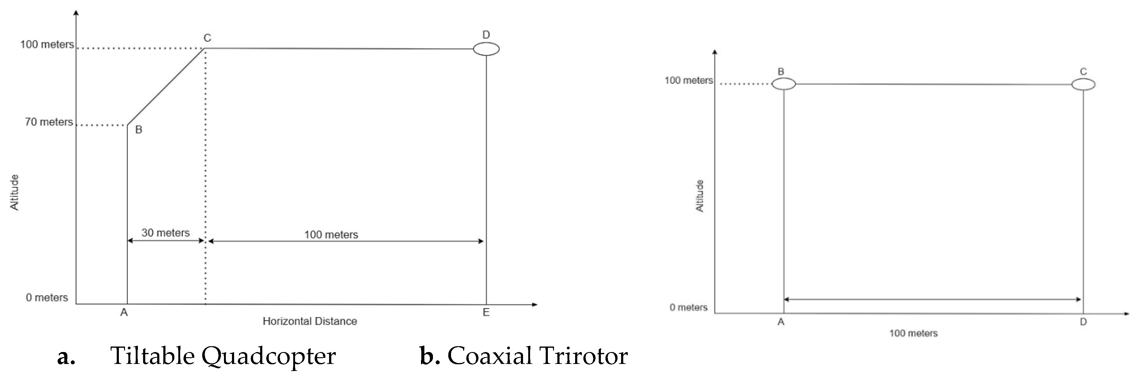
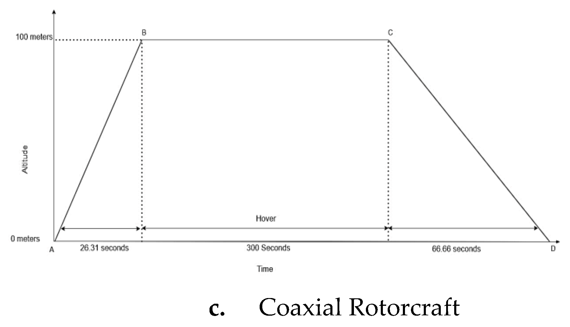
Three mission profiles as shown in
Figure 1 were meticulously created, keeping in mind the broad nature of the problem statement, the zones and scope of operation for all the three most promising configuration.
All the mission profiles shown in
Figure 1, despite of the configurations satisfy and fulfil all the requirements posed in the problem statement. The study of the Martian lower stratum being our major objective, keen interest is taken in designing the mission profile in such a way that the UAV shall stay in the air for a sufficient of amount of time, thus allowing better scientific experiments and data collection. In the tiltable quadcopter, a long cruise is integrated with hover flight while in the co axial flight, focus is given on the increased hover time and a much less steep path of the descent. In case of coaxial trirotor, hover flight is initiated twice with added cruise flight. All of these features converge to a single point and objective, that is for the better study of the Martian atmosphere. Higher the time I’m keeping the UAV airborne, much better is the collection and study of data by the payload of the UAV.
3. Selection of Airfoil
The unique characteristics of the Martian atmosphere necessitate the careful selection of airfoils and the design of corresponding rotor blades for the tiltable Quadcopter. Rotor blades on Mars are expected to perform optimally under extreme conditions, such as low density, low pressure, and extreme temperatures. The airfoil selection must enable the rotor blades to generate high lift, operate at low Reynolds numbers, and perform efficiently at high Mach numbers, relative to the speed of sound on Mars. With an average surface temperature of around 208K, the speed of sound is approximately 230-240 m/s. This results in the formation of shock waves at lower velocities, particularly at the rotor blade tips, which disrupts the flow and exponentially increases drag, reducing the lift capability of the airfoil. This poses significant limitations on airfoil selection and rotor blade design Computational studies show that thin, high-camber airfoils are most effective in ultra-low Reynolds number conditions, aligning with Ingenuity’s successful use of this design. Based on survey, the following selections for the airfoil were made.
The NACA 0012 airfoil as shown in
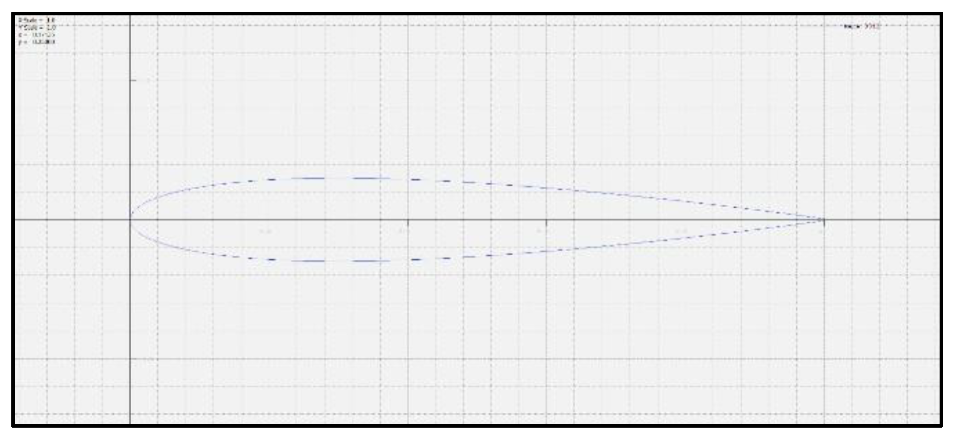
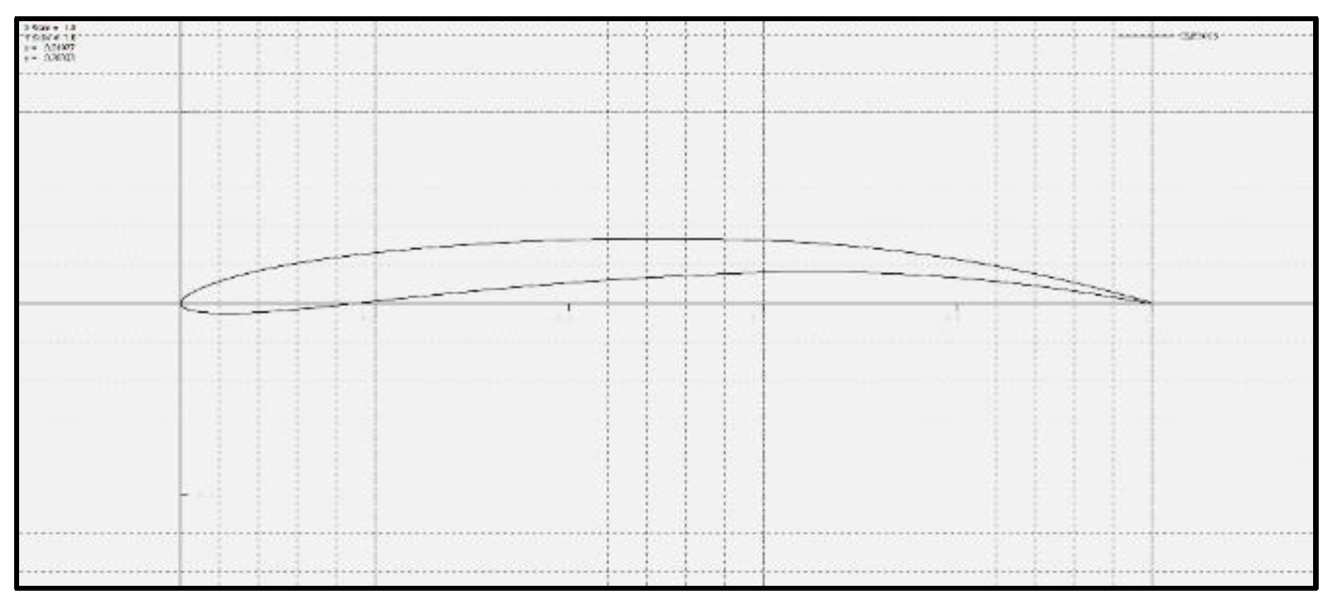
Figure 2 symmetrical with no camber, is positioned near the rotor hub, i.e in the inboard section where its aerodynamic contributions are minimal due to lower velocities. Its primary function is to provide structural support against centrifugal forces. The CLF 5605 as shown in
Figure 3, with its high camber and thin trailing edge, generates sufficient lift in Mars' low-Reynolds-number, low-density atmosphere. With a maximum thickness ratio of 5.0% and a camber ratio of 4.9%, this airfoil is well-suited for the specific atmospheric conditions of Mars.
3.1. CAD Design of the Rotor
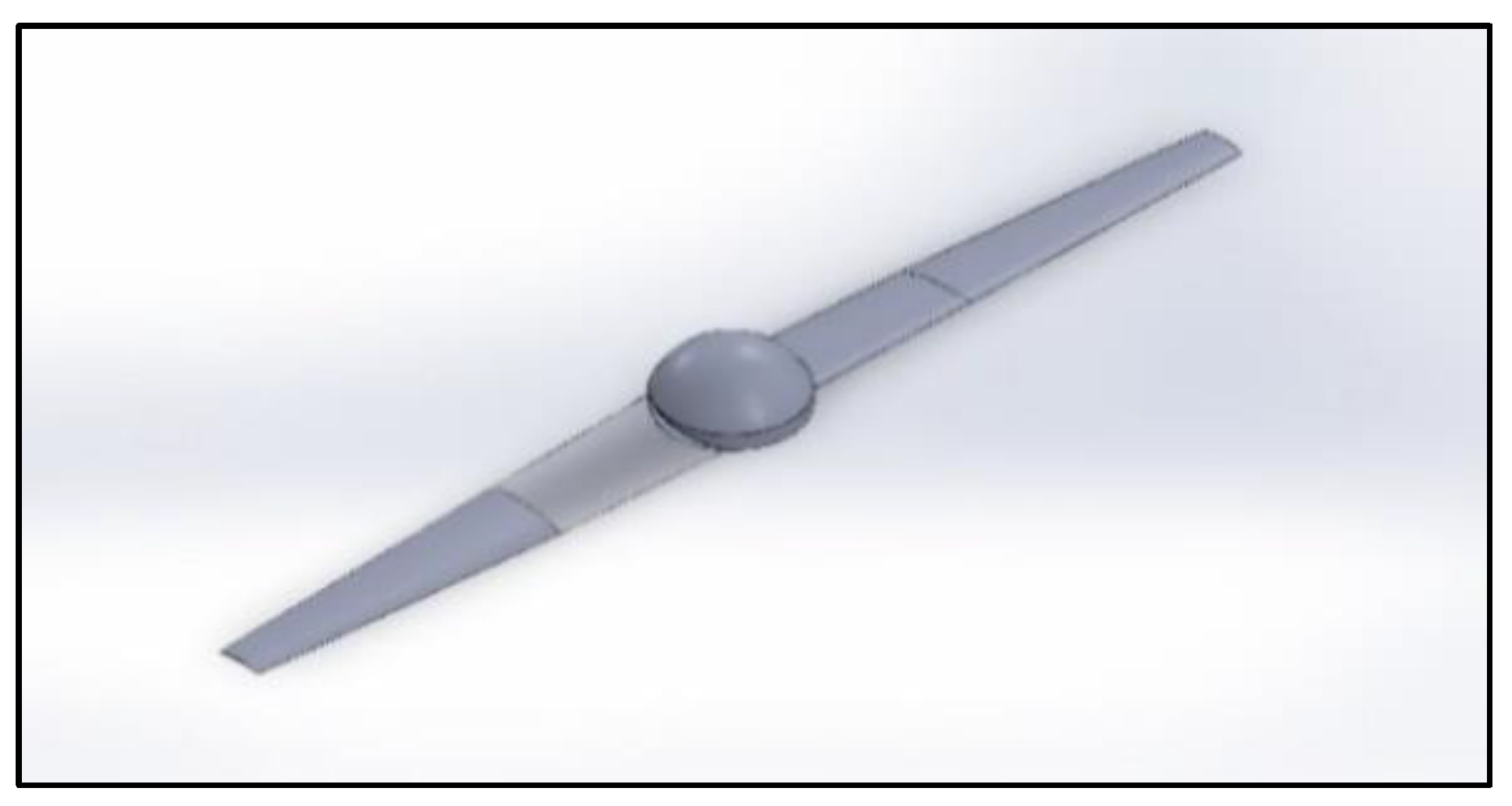
The 3D design has both the NACA 0012 and CLF 5605 airfoils, positioned at 1/4th and 3/4th of the rotor radius, respectively. The root chord measures 0.1 meters, while the tip chord measures 0.05 meters, with the total rotor diameter extending to 1.21 meters. The hub diameter is set at 0.07 meters. The finalized 3D rendering of the rotor configuration is illustrated in
Figure 4. Validation of the design and selected airfoils was conducted through computational fluid dynamics analysis.
4. Computational Analysis of The Rotor
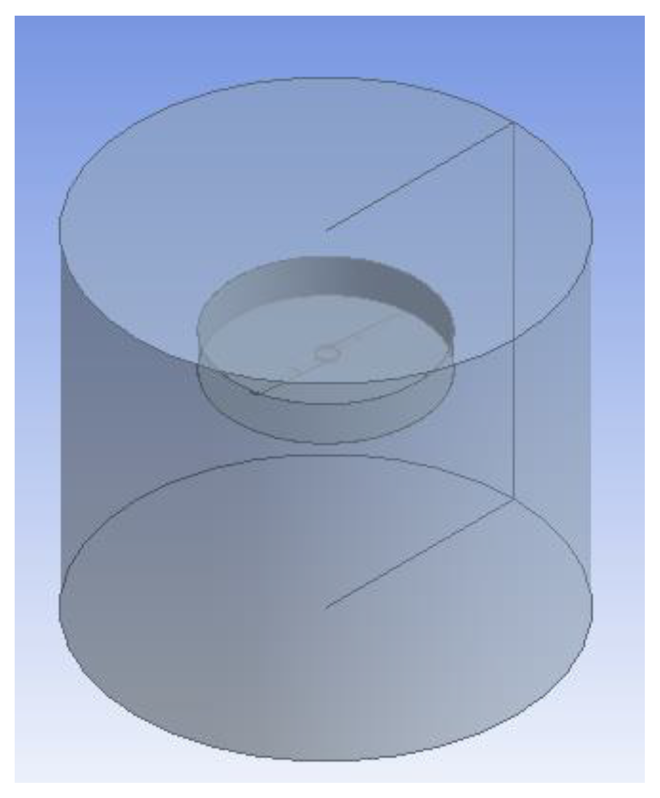
In this paper, a flow simulation on UAV rotor blade is proposed to conduct by using ANSYS Fluent. The geometry is simplified in the design modeler of Fluent module. In order to do the fluid simulation, the domain that contains the enclosure volume of the rotor blade is defined as shown in
Figure 5. The rotor blade is enclosed in the static part of the domain and when the base parameters of atmospheric data is applied for the simulation, the software applies those parameters as data for static part of the volume.
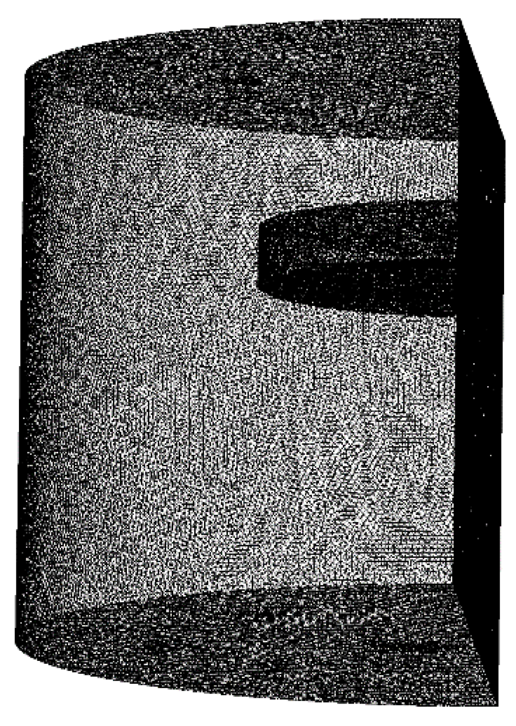
For the proposed computational setup of this paper, the interaction of flow lines with solid body gives insights into the transition phase of the flow at different CFD stations (CFD stations are considered as locations from the hub of the rotor, out in the radial direction towards the tip of the rotor). Once the bounding box is created in the design modeler, the rotor design is imported into the mesh module. The face meshing is assigned to the blade and the boundary enclosure with element size of 3 mm and 25 mm respectively as shown in
Figure 6. The nodes and elements of 728674 and 3983064 is generated.
Once the mesh is created around the solid body, the body is converted into the form which can be interpreted by the solver.
Table 1 shows the solver setup
5. Performance
The determination of the performance specifications of the UAV configurations is done by finding out many parameters like Thrust, Induced Velocity, Induced power, Profile power, Total power, Figure of Merit, etc. The induced velocity is an important parameter which is given by
where, A is the Rotor Disc Area.
Induced power is the power required to keep the air accelerated by the propeller [
18]. It can be determined by
Pi = T. vi where, T is the propellor thrust.
Profile power is the power required to turn the rotor in air and overcome profile drag [
18]. It is determined using
where, n is the rotational speed per second.
The Figure of Merit can be determined by the expression
The parameters are derived for the UAV of mass 30Kg (tolerance of ±2 Kg has been taken into account), Diameter of a propeller 1.21 meters, based on stowage requirements, mean chord of 0.078 meters and Tip Mach number less than 0.7 [
19]. The Coefficient of lift of the rotor blade, CL is derived to be 0.34981441 using Ansys Fluent.
For the Tiltable quadcopter configuration, (T/W) =1 for hover, (T/W)>1 for vertical climb, inclined climb and cruise, (T/W) = 0.9 for controlled vertical descent, the total power required for one flight comes out to be 16.455 kW for a total flight time of 286.28 seconds for the proposed mission profile. For the Coaxial rotorcraft configuration [
20], (T/W) =1 for hover, (T/W)>1 for vertical climb, (T/W) = 0.9 for controlled vertical descent and constant thrust is applied during each phase of flight, the total power required for one flight comes out to be 6.471 kW for a total flight time of 392.97 seconds for the proposed mission profile. For the Coaxial trirotor configuration, (T/W) =1 for hover, (T/W)>1 for vertical climb, (T/W) = 0.9 for controlled vertical descent and differential thrust is used to achieve forward flight, the total power required for one flight comes out to be 25.43 kW for a total flight time of 257.88 seconds for the proposed mission profile.
6. Propulsion System Sizing and Energy Balance
When designing a propulsion system for Mars exploration, careful attention to energy balance is critical. The Martian atmosphere and gravity present unique challenges, requiring innovative approaches and precise engineering solutions. At low altitudes, particularly up to 100 meters, studying the boundary layer is essential for understanding the aerodynamic and environmental effects that impact propulsion systems in Martian conditions. This detailed analysis allows engineers to optimize propulsion designs, reducing drag and increasing thrust efficiency. When developing a solar-powered propulsion system for Martian missions, several technical factors must be considered. Efficient solar energy capture, weight minimization, and system reliability in extreme Martian environments are of utmost importance. The propulsion system needs to convert solar energy into thrust effectively, while also withstanding Mars' harsh climate. Choosing appropriate UAV operations involves considering terrain, atmospheric conditions, and specific mission goals to ensure the best possible performance. Additionally, understanding irradiance patterns near the equator is vital, as it affects solar panel efficiency and the overall output of solar-powered systems on Mars. These technical considerations are crucial for the success of Martian exploration missions. For designing the propulsion system, some assumptions were considered, Backup for 1 flight power consumption has been included in the Energy balance for maintain the waiting period between two flight (after recharging of battery) is 100s . Assumed sun peak hour is 9 hrs as length of the solar day is 12 hour 40 minutes. A payload power of approx. 97.5 W power were considered for propulsion system sizing.
Table 2,
Table 3 and
Table 4 shows the Power consumption of Tiltable Quadcopter, Coaxial Rotorcraft and Coaxial Trirotor Respectively.
6.1. Energy Balance
Energy Balance Solar-powered UAVs rely on a delicate equilibrium known as energy balance. This balance intricately manages energy harvested from solar cells against the demands of propulsion and onboard systems. The goal is prolonged flight endurance and autonomy, achieved through optimizing energy generation and consumption. Understanding this balance is critical for designing efficient and sustainable solar-powered UAVs.
Optimizing energy generation and consumption is essential for the design of efficient and sustainable solar-powered UAVs. The photovoltaic (PV) power can be calculated using the formula: Daily consumption multiplied by solar efficiency divided by sun peak hours, which ensures that the energy harnessed is maximized during optimal sunlight conditions
(Wang et al., 2023) [
21]
. Additionally, the battery bank capacity is determined by dividing daily consumption by the depth of discharge (DOD), then factoring in efficiency and system voltage, which is crucial for maintaining energy reserves during non-sunny periods
(Li et al., 2022) [
22]
. The weight of the battery, a critical factor in UAV design, is calculated by multiplying nominal battery voltage by battery capacity and dividing by energy density, ensuring that the UAV remains lightweight while maintaining sufficient power
(Fodhil & Gherouat, 2024) [
23]
. These calculations collectively contribute to the development of UAVs that can achieve prolonged flight times and operational efficiency, as demonstrated in various studies
(Buzdugan et al., 2023) (Wang et al., 2023) [
24,
25]
.
Table 5 represents the Battery Specifications for each of the configurations.Energy Density of the battery is 650 KJ/Kg which is 180.55 wh/kg. The panel efficiency is 17% and depth of discharge (DOD) is taken as 75% as 25 % charges should be reserved. The Efficiency of the battery is taken as 85%.
Table 6 shows the required panel area for each of the configuration.
Solar Irradiance value at 100m altitude is 586.2 W/m2 and irradiance attenuation factor at 100m is 0.70
7. Vehicle Sizing and Mass Breakdown
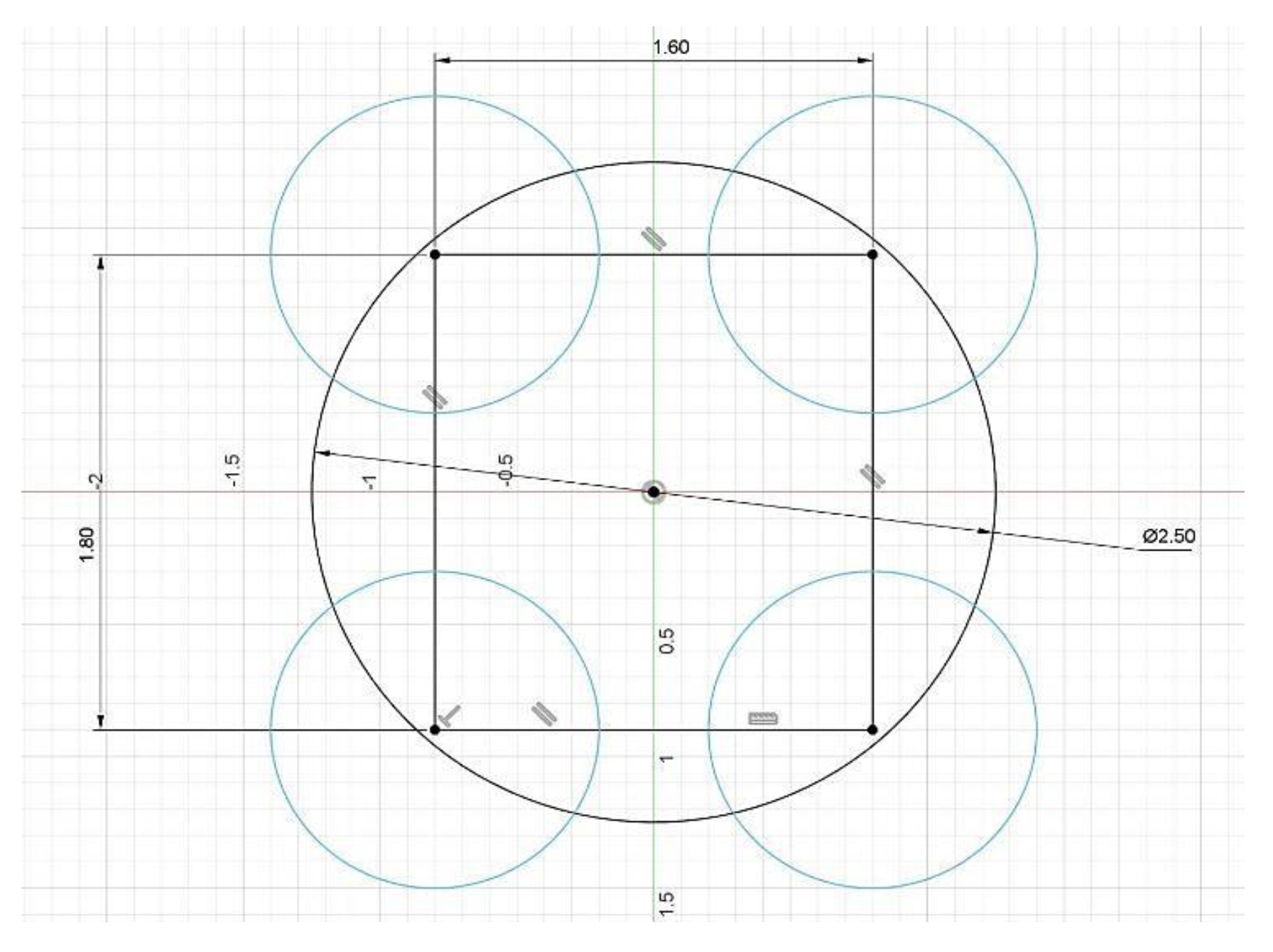
Vehicle sizing is a critical step in UAV design, as it helps determine the optimal size and shape of the UAV based on mission requirements and constraints. For the three configurations under consideration—Tiltable Quadcopter, Coaxial Rotorcraft, and Coaxial Tri-Rotor—vehicle sizing was performed with respect to the stowage diameter and mission objectives. The Tiltable Quadcopter, shown in Figure X, has a rotor diameter of 1.21 meters and a rectangular frame measuring 1.8 meters in length and 1.6 meters in breadth. This configuration provides ample space for payload placement and ensures sufficient rotor separation, making it ideal for atmospheric studies on Mars. In comparison, the Coaxial Rotorcraft features a smaller square frame of 0.6 meters to enhance aerodynamic efficiency, while minimizing interference from the downward rotor airflow. Lastly, the Coaxial Tri-Rotor has an equilateral triangle frame with 2-meter sides, designed to accommodate larger rotors and ample payload space. Based on the analysis, the Tiltable Quadcopter emerges as the most effective design for Mars due to its superior stability, control, and space for scientific instrumentation.
Figure 7, shows the frame dimensions of tiltable quadcopter.
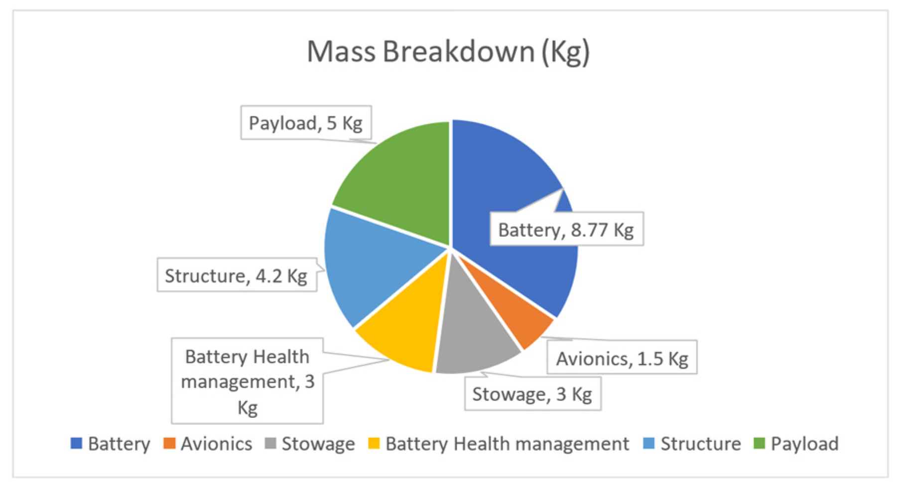
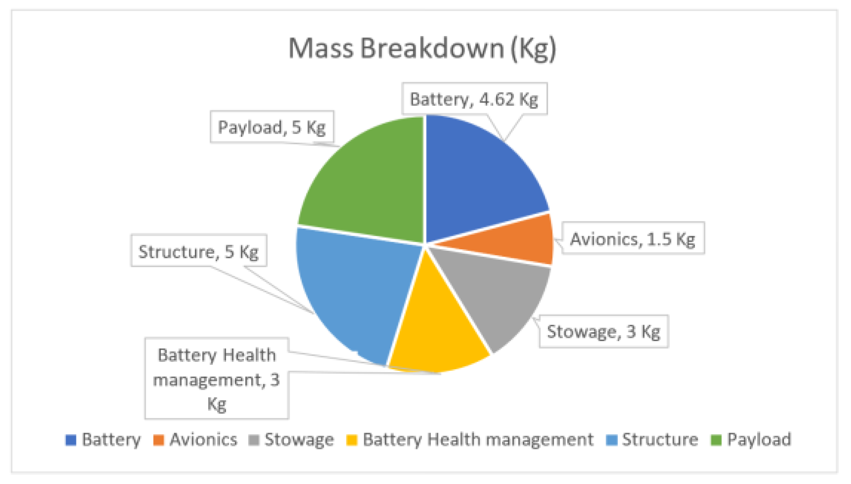
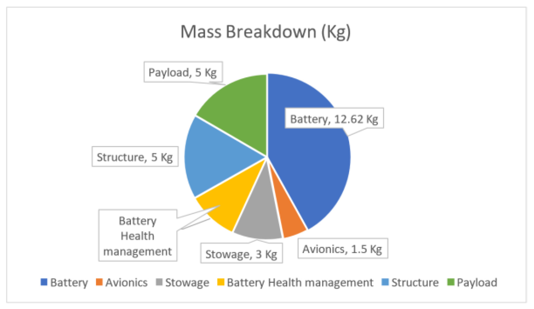
7.1. Mass Breakdown
The mass breakdown of each configuration is done by keeping a limit of maximum 30 Kg. Additionally, a tolerance of ±5 Kg has been considered for each configuration in case of any deviation from the above-mentioned limit. In case, the total mass of any configuration exceeds 30 Kg, the payload weight will be reduced to the minimum as per the problem statement and the fixed stowage mass will also account for a part of structural mass due to the team’s novel concept of stowage. The total masses of tiltable quadcopter, coaxial rotorcraft and coaxial trirotor are 25.47Kg, 22.34Kg, 30.01Kg respectively, which are broken down as shown in
Figure 8,
Figure 9 and
Figure 10.
8. Identification of Stowage Mechanism
Stowage of a UAV or any payload in an aeroshell refers to the mechanism for safely transporting, landing, and deploying the payload into the interplanetary atmosphere. A major constraint is size, which adds complexity to the UAV's design, including the number of folding points or rotation mechanisms required. Modularity refers to how compactly components can fit within limited space. For our mission, the UAV must fit within a 2.5m aeroshell without compromising structural integrity or deployment functionality.
Various stowage concepts have been explored for Martian UAVs. (
Withrow, Shannah, et al.) [
19] chose drooped flat blades with pyrotechnic wires for deployment in their advanced coaxial rotorcraft design. (
Radotich, Micheal, et al.) [
26] examined overlapping blades, a concept also applied in NASA's Ingenuity helicopter. Foldable or retractable arms were explored for multirotor configurations, including tiltable quadcopters and hexacopters, inspired by Earth-based designs. (
Tuna, Turcan, et al.) [
27] designed a self-deployable quadcopter using a gear, crank, and shaft system, though it added complexity and weight. (
Xiu, Haohua, et al.) [
28] implemented foldable arms with servo motors to increase compactness, and (
A. Datta, et al.) [
29] proposed doubled-folded rotors with retention links and hinges for a coaxial rotorcraft. Ultimately, the selection of the best stowage mechanism for each configuration must consider factors like aeroshell height and deployment type.
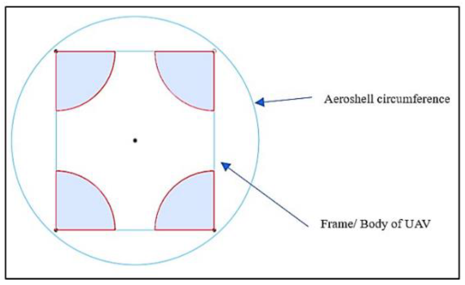
The conceptualized tiltable quadcopter design features a fixed frame and arms to enhance stowage robustness and compactness while providing sufficient space for payload sensors. The UAV is housed inside a circular aeroshell, with the frame designed as a compact rectangle or near-square, placing rotors at each corner. Each rotor has a diameter of 1.21m, with enough spacing between them to minimize flow interaction. In stowage mode, the rotor blades align in a single plane toward the center of the frame. Upon deployment, centrifugal force allows the blades to return to their flying configuration. This mechanism ensures no need for additional external power sources or complex actuators.
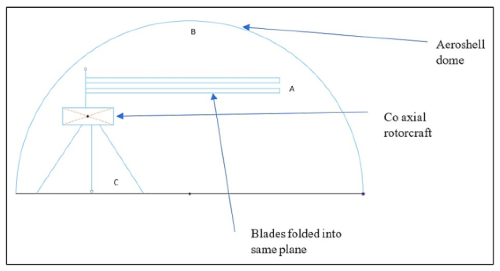
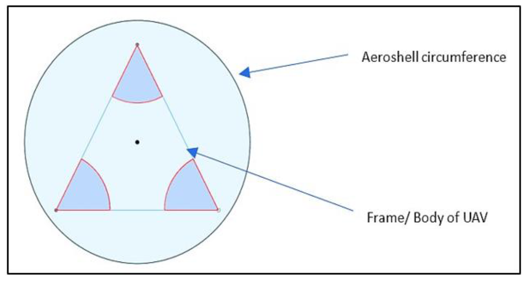
For the coaxial rotorcraft, two rotors with 2 blades each are placed on the same axis. The payload housing is compact to avoid interference with rotor stowage. The rotor diameter is 4 meters, which can fit within a 2.5m aeroshell. Upon exposure, the rotors deploy using either external power sources or centrifugal force, ensuring no power loss during flight. The coaxial tri-rotor configuration follows a similar stowage concept, where the frame is triangular, concentric with the aeroshell circumference. Each rotor has a diameter of 1.5 meters. The system applies the same principle of rotational dynamics for rotor deployment, though the power required increases due to the double rotor setup, which can be compensated by using either onboard or external power sources. Additionally, stowage mechanisms for the landing skids were considered. Options include vacuum-sealed polymer cushion-based pads, which inflate during landing, or telescopic landing gears that extend using gravity. These ensure minimal space usage during stowage and reliable support upon landing.The stowage for all three configurations has been visualized in
Figure 11,
Figure 12 and
Figure 13, respectively, depicting the compactness.
9. Conclusions
This research has rigorously evaluated three UAV configurations—tiltable quadcopter, coaxial rotorcraft, and coaxial trirotor—for Martian boundary layer exploration, focusing on their aerodynamic efficiency, propulsion systems, and stowage capabilities. The tiltable quadcopter, with its rectangular frame and optimized rotor layout, demonstrated superior aerodynamic performance and stowage efficiency, featuring a rotor diameter of 1.21 meters and a total power requirement of 16.45 kW for a flight duration of 286.28 seconds. Its compact structure and minimized interference between rotors provide enhanced lift and reduced drag under Mars’ low-Reynolds number conditions. Computational simulations validated the rotor design, revealing effective flow dynamics and reduced flow separation, critical for maintaining operational efficiency in Mars' thin atmosphere. Additionally, the energy balance analysis, accounting for solar irradiance and battery capacity, confirmed the tiltable quadcopter as the most efficient configuration for extended Martian missions. These findings suggest that the tiltable quadcopter offers optimal performance for sustained Martian atmospheric exploration, with future improvements potentially enhancing solar energy capture, weight reduction, and rotor aerodynamics for even greater efficiency.
10. Future Work
The continued advancement of UAV technologies for Martian exploration presents several promising avenues for future research.
Developing advanced photovoltaic materials and adaptive solar panels can optimize energy absorption, improving UAV flight duration in varying Martian conditions.
Lightweight materials, like carbon composites, should be explored to reduce UAV weight, improving performance and payload capacity for longer missions.
Advanced CFD simulations and individual blade control (IBC) systems can enhance rotor efficiency, reducing drag and improving lift under Martian atmospheric conditions.
Machine learning-based autonomous navigation systems can adapt flight paths, energy use, and data collection in real-time, increasing mission efficiency on Mars.
By addressing these areas in future will enhance the operational capabilities of UAVs for Martian boundary layer exploration, enabling more efficient, longer-duration missions with greater scientific output.
Acknowledgement
The authors would like to express their gratitude to the Department of Aerospace Engineering at Chandigarh University for providing the necessary resources and support for this research. All authors have contributed equally to this work, with each taking responsibility for specific tasks:
Nandan Kumar Jha: Martian Irradiance Model study, Propulsion system design and energy balance analysis.
Aditya Gautam: The aerodynamic study, airfoil selection & Rotor performance optimization.
Bhakti Sachin Malve: Payload Study & computational fluid dynamics (CFD) simulations for rotor.
Nachiketh Nadig: Martian Atmosphere study, Conducted research on airfoil selection and stowage strategies.
Gourav Mehta: CAD model design.
Jitesh N: Assistance in CAD model Design
We would like to extend our heartfelt gratitude to Dr. Gurmail Singh Malhi for his invaluable guidance, expertise, and encouragement throughout the course of this project. His insights were instrumental in shaping the success of our work.
We are also deeply thankful to Dr. Dharmahinder Singh Chand, Head of the Department of Aerospace Engineering, for his unwavering support and invaluable advice. His leadership and commitment to fostering a collaborative and innovative environment played a crucial role in the completion of this project.
Nomenclature
|
UAV - Unmanned Aerial Vehicle |
|
CFD - Computational Fluid Dynamics |
|
NACA - National Advisory Committee for Aeronautics (Airfoil) |
|
CLF - Airfoil code used in rotor design (specific to the study) |
|
IBC - Individual Blade Control |
|
EUV - Extreme Ultraviolet |
|
MAVEN - Mars Atmosphere and Volatile Evolution (NASA Mission) |
|
EUVM - EUV Monitor |
|
T/W - Thrust-to-Weight ratio |
|
PV - Photovoltaic |
|
DOD - Depth of Discharge |
|
RPM - Revolutions Per Minute |
|
Cl - Coefficient of Lift |
|
Cd - Coefficient of Drag |
|
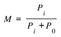
Pi - Induced Power |
|
Po - Profile Power |
References
- Ge, J., Xiang, J., Li, D., and Bai, W., “Conceptual Design of a Tilt-Rotor Unmanned Aerial Vehicle for Mars Exploration,” Acta Astronautica, Vol. 222, 2024, pp. 391–402. [CrossRef]
- Sopegno, L., Martini, S., Pedone, S., Fagiolini, A., Rutherford, M. J., Stefanovic, M., Rizzo, A., Livreri, P., and Valavanis, K. P., “An Advanced Hexacopter for Mars Exploration: Attitude Control and Autonomous Navigation,” IEEE Transactions on Aerospace and Electronic Systems, Vol. 60, No. 3, 2024, pp. 3569–3581. [CrossRef]
- Youhanna, V., Felicetti, L., and Ignatyev, D., “Preliminary Investigation into Future Martian Multicopter Configurations,” ICAS, 2024, pp. 1–14. [CrossRef]
- Bețco, D., Pârvu, P.-V., and Ciudin, S., “Autonomous Navigation for the Martian Inspection Drone,” Acta Astronautica, Vol. 216, 2023, pp. 55–63. [CrossRef]
- Ayele, W., and Maldonado, V., “Conceptual Design of a Robotic Ground-Aerial Vehicle with an Aeroelastic Wing Model for Mars Planetary Exploration,” Aerospace, Vol. 10, No. 5, 2023, p. 404. [CrossRef]
- Zhao, P., Gao, X., Yan, Z., Li, Y., Wu, J., and Deng, Z., “Investigation of Aerodynamic Performance of Coaxial Rotors for Mars Rotorcraft,” IEEE International Conference on Mechatronics and Automation, 2023. [CrossRef]
- Ruiz, M. C., and D’Ambrosio, D., “Aerodynamic Optimization and Analysis of Quadrotor Blades Operating in the Martian Atmosphere,” Aerospace Science and Technology, Vol. 132, 2022, p. 108047. [CrossRef]
- Küçükoğlu, O., Sakaoğlu, S., and Uzol, N. S., “Aerodynamic Performance Predictions of Mars Helicopter Co-Axial Rotor in Hover by Using Unsteady CFD Simulations,” Sustainable aviation, 2023, pp. 83–89. [CrossRef]
- Koning, W. J. F., Johnson, W., and Allan, B. G., “Generation of Mars Helicopter Rotor Model for Comprehensive Analyses,” NASA Ames Research Center, Technical Report ARC-E-DAA-TN50660, Moffett Field, CA, 2018.
- Schulman, P., Berndt, S.-H., Roman, C., and Tan, X., “Computational Fluid Dynamics Modeling Analysis of a Martian Rotorcraft with Individual Blade Control,” ASME Letters in Dynamic Systems and Control, Vol. 3, No. 2, 2023. [CrossRef]
- Thiemann, E. M. B., Chamberlin, P. C., Eparvier, F. G., Templeman, B., Woods, T. N., Bougher, S. W., and Jakosky, B. M., “The MAVEN EUVM Model of Solar Spectral Irradiance Variability at Mars: Algorithms and Results,” Journal of Geophysical Research Space Physics, Vol. 122, No. 3, 2017, pp. 2748–2767. [CrossRef]
- Balalla, D. T., Nguyen-Huy, T., and Deo, R., “MARS Model for Prediction of Short- and Long-Term Global Solar Radiation,” Elsevier eBooks, 2020, pp. 391–436. [CrossRef]
- Landis, G., Kerslake, T., Scheiman, D., and Jenkins, P., “Mars Solar Power,” 2nd International Energy Conversion Engineering Conference, 2004. [CrossRef]
- Rajendran, P., and Smith, H., “Modelling of Solar Irradiance and Daylight Duration for Solar-Powered UAV Sizing,” Energy Exploration & Exploitation, Vol. 34, No. 2, 2016, pp. 235–243. [CrossRef]
- Rajendran, P., Smith, H., and Masral, M. H. B., “Modeling and Simulation of Solar Irradiance and Daylight Duration for a High-Power-Output Solar Module System,” Applied Mechanics and Materials, Vol. 629, 2014, pp. 475–480. [CrossRef]
- Withrow, S., Johnson, W., Young, L. A., Cummings, H., Balaram, J., and Tzanetos, T., “An Advanced Mars Helicopter Design,” ASCEND 2020, 2020. [CrossRef]
- Sierra, G., Orchard, M., Goebel, K., and Kulkarni, C., “Battery Health Management for Small-Size Rotary-Wing Electric Unmanned Aerial Vehicles: An Efficient Approach for Constrained Computing Platforms,” Reliability Engineering & System Safety, Vol. 182, 2018, pp. 166–178. [CrossRef]
- “Rotor Blade Profile Drag.” https://aerodynamics4students.com/aircraft-performance/blade-profile-drag.php.
- Johnson, W., Withrow-Maser, S., Young, L., Malpica, C., Koning, W. J. F., Kuang, W., Fehler, M.; et al., “Mars Science Helicopter Conceptual Design,” NASA Ames Research Center, Technical Report ARC-E-DAA-TN78199, Moffett Field, CA, 2020.
- Ramasamy, M., “Hover Performance Measurements toward Understanding Aerodynamic Interference in Coaxial, Tandem, and Tilt Rotors,” Journal of the American Helicopter Society, Vol. 60, No. 3, 2015, pp. 1–17. [CrossRef]
- Wang, H., Li, P., Xiao, H., Zhou, X., and Lei, R., “Intelligent Energy Management for Solar-Powered Unmanned Aerial Vehicle Using Multi-Objective Genetic Algorithm,” Energy Conversion and Management, Vol. 280, 2023, p. 116805. [CrossRef]
- Li, K., Wu, Y., Bakar, A., Wang, S., Li, Y., and Wen, D., “Energy System Optimization and Simulation for Low-Altitude Solar-Powered Unmanned Aerial Vehicles,” Aerospace, Vol. 9, No. 6, 2022, p. 331. [CrossRef]
- Fodhil, F., and Gherouat, O., “Optimal Design of an Off-Grid Photovoltaic-Battery System for UAV Charging in Wildlife Monitoring,” Lecture notes in networks and systems, 2024, pp. 157–165. [CrossRef]
- Alexandru, T., “Numerical Modeling of an Energy Management System for a Uav Design Powered by Photovoltaic Cells,” Review of the Air Force Academy/Revista Academiei Forţelor Aeriene “Henri Coandă,” Vol. XX, No. 2, 2023. [CrossRef]
- Wang, L., Tripathi, S., Zhang, R., Cheng, N., and Wang, M., “Optimal Charging Profile Design for Solar-Powered Sustainable UAV Communication Networks,” arXiv (Cornell University), 2023. [CrossRef]
- Radotich, M., Withrow-Maser, S., deSouza, Z., Gelhar, S., and Gallagher, H., “A Study of Past, Present, and Future Mars Rotorcraft,” in9th Biennial Autonomous VTOL Technical Meeting, January 2021.
- Tuna, T., Ovur, S. E., Gokbel, E., and Kumbasar, T., “Design and Development of FOLLY: A Self-Foldable and Self-Deployable Quadcopter,” Aerospace Science and Technology, Vol. 100, 2020, p. 105807. [CrossRef]
- Xiu, H., Xu, T., Jones, A. H., Wei, G., and Ren, L., “A Reconfigurable Quadcopter with Foldable Rotor Arms and a Deployable Carrier,” 2017 IEEE International Conference on Robotics and Biomimetics (ROBIO), 2017. [CrossRef]
- Datta, A., Roget, B., Griffiths, D., Pugliese, G., Sitaraman, J., Bao, J., Liu, L., and Gamard, O., “Design of a Martian Autonomous Rotary-Wing Vehicle,” Journal of Aircraft, Vol. 40, No. 3, 2003, pp. 461–472. [CrossRef]
|
Disclaimer/Publisher’s Note: The statements, opinions and data contained in all publications are solely those of the individual author(s) and contributor(s) and not of MDPI and/or the editor(s). MDPI and/or the editor(s) disclaim responsibility for any injury to people or property resulting from any ideas, methods, instructions or products referred to in the content. |
© 2024 by the authors. Licensee MDPI, Basel, Switzerland. This article is an open access article distributed under the terms and conditions of the Creative Commons Attribution (CC BY) license (http://creativecommons.org/licenses/by/4.0/).