
Submitted:
28 November 2024
Posted:
29 November 2024
You are already at the latest version
Abstract
A new method of producing metal powders for additive manufacturing by the atomization of free-falling melt streams using pulsed cross-flow gaseous shock or detonation waves is proposed. The method allows the control of shock/detonation wave intensity (from the Mach number of 4 to about 7), as well as the composition and temperature of the detonation products by choosing proper fuels and oxidizers. The method is implemented in laboratory and industrial setups and preliminarily tested for melts of three materials, namely, Zinc, Aluminum alloy AlMg5, and stainless steel AISI 304 possessing significantly different properties in terms of density, surface tension, and viscosity. Pulsed shock and detonation waves used for the atomization of free-falling melt streams are generated by the pulsed detonation gun operating on the stoichiometric mixture of liquid hydrocarbon fuel and gaseous oxygen. The analysis of solidified particles and particle size distribution in the powder is studied by microscopy, fraction separation by sifting on sieves, laser diffraction wet dispersion method (WDM), and atomic force microscopy (AFM). The operation process is visualized by a video camera. The minimal size of the powders obtained by the method is shown to be as low as 0.1 to 1 mm, while the maximum size of particles exceeds 400–800 mm. The latter is explained by the deficit of energy in the shock-induced cross-flow for the complete atomization of the melt stream, in particular dense and thick (8 mm) streams of the stainless-steel melt. The mass share of particles with a fraction of 0–10 μm can be at least 20%. The shape of the particles of the finest fractions (0–30 and 30–70 μm) is close to spherical (zinc, aluminum) or perfectly spherical (stainless steel). The shape of particles of coarser fractions (70–140 μm and larger) is getting more irregular. Zinc and aluminum powders contain agglomerates in the form of particles with fine satellites. The content of agglomerates in stainless-steel powders is very low. In general, the preliminary experiments show that the proposed method for the production of finely dispersed metal powders looks promising in terms of powder characteristics and cost.
Keywords:
metal powder
; gas atomization
; free-falling melt stream
; pulsed detonation gun
; particle size distribution
; zinc
; aluminum
; stainless steel
; additive manufacturing
1. Introduction
Currently, additive manufacturing (AM) technologies for prototyping and fabricating various parts of machines are actively developing [1,2]. Along with household 3D printers using various plastics, 3D printers operating on various metals and alloys have been developed and globally applied in industry. The printing technology in such printers usually consists of layer-by-layer sintering of metal powder using powerful laser radiation. As this technology becomes more widespread, so do the requirements for the quality and accuracy of printing parts, which depends both on the properties of the printer itself and on the quality of the metal powder used. The quality of the metal powder affects the resulting porosity of the material after printing and the uniformity of shrinkage of the parts. To reduce the porosity of the material, it is necessary to use powders with a minimum particle size. To obtain uniform shrinkage of the parts after printing, it is necessary to ensure that the shape of the powder particles is close to spherical. Thus, the AM technology based on the laser powder bed fusion technique requires spherical particles 10–60 µm in size [3].
The production of powders, despite the variety of methods, is the most labor-intense and expensive stage of the technological process. The physical, chemical, and technological properties of powders as well as the shape of the particles depend on their production technology. The main industrial technologies for producing metal powders are: (i) mechanical grinding of metals in vortex, vibration, and ball mills [4,5]; (ii) centrifugal atomization [6,7]; (iii) atomization of metal melts with compressed cold gas (air [8], nitrogen [9], argon, helium [10], etc. [11,12]), hot gas [13] or steam [14], liquified/cryogenic gas [15,16], or liquid (water [17] and oil [18]) jets under high pressure; (iv) ore or scale recovery [19]; (v) electrolytic deposition of metals from solutions [20]; (vi) application of a strong electrical current to a metal rod in vacuum [21]; plasma atomization [22,23,24], wire explosion [25], etc. In industrial conditions, special powders are also obtained by precipitation, carburization, thermal dissociation of volatile compounds (carbonyl method) and other technologies.
Despite each of these technologies exhibits its pros and cons and water-assisted melt atomization technologies are most commercially available, the metal powders for laser AM are commonly produced by melt atomization technologies with high-pressure gas jets [26]. These technologies are attractive in terms of powder characteristics (particle size distribution (PSD), particle shape, particle internal structure and surface morphology, powder purity, density and flowability) and economic considerations. Atomization of melt streams by continuous high-pressure gas jets in conventional gas atomizers occurs at gas pressures up to about 4 MPa and gas velocities at a nozzle exit up to Mach number 3 [27]. Since the melt is atomized to fine droplets due the dynamic interaction of liquid stream with gas jets, the efficiency of the atomization process is proportional to the gas-to-metal momentum ratio and relative interphase area. Therefore, the properties of the powder arising after droplet solidification are affected by the types of gas and melt used in the atomization process [28] as well as gas and melt parameters, such as atomization gas pressure and temperature, melt stream shape and dimensions, and melt temperature [29]. Higher gas pressure allows producing finer and more spherical particles [30]. The atomization gas temperature also affects the particle shape and size [31]. Higher flow rates of melt stream typically lead to finer powder particles [32]. According to [33], the characteristic times for particle spheroidization for gas-atomized powder are usually few orders of magnitude lower than the times required for droplet solidification. Therefore, the shape of gas-atomized powder particles is usually spherical, which is an important prerequisite for acceptable powder density and flowability [34] as opposed to particles of nonspherical shape [35]. The surface of gas-atomized particles is usually smooth and contains no satellites [36]. The PSD of gas-atomized solidified powders is usually log-normal [37]. It is worth noting that very fine particles promote particle agglomeration and deteriorate powder flowability due to interparticle forces [38].
We propose herein a new method for obtaining metal powders by the atomization of free-falling melt streams using pulsed cross-flow gaseous shock or detonation waves patented by us in [39]. In the method, the chemical energy of fuel used for the generation of pulsed shock or detonation waves is directly converted into the mechanical work of melt stream fragmentation thus avoiding the use of high-pressure gases. Moreover, this method allows the control of shock/detonation wave intensity (from the Mach number 4 to about 7), as well as the composition and temperature of the detonation products by choosing proper fuels and oxidizers. By other words, it allows creating the high-temperature (above 1800 K) atomizing gas with oxidizing/reducing properties containing various target substances for melt modification. The new and distinctive feature of this method is that the free-falling melt stream can be subject to multiple impacts of cross-flow shock or detonation waves rather than a single impact of a shock wave often used in the literature in experimental studies of liquid droplet [40,41] and liquid jet [42] atomization. As for the gas atomization of melt streams in a shock-induced cross-flow, there are only few experimental studies in the literature. Thus, the authors of [43] study experimentally the shock-induced cross-flow gas atomization of a liquid stream of room-temperature eutectic alloy of gallium, indium and tin using high speed digital in-line holography videos to obtain time-resolved droplet statistics. The shock wave Mach number in the experiments is low and attains 1.5. It is claimed that the shock-induced atomization of liquid metals is a rich and under-explored research area.
In this paper we imply that multiple impacts of shock and detonation waves on the free-falling melt stream can provide not only primary and secondary atomization of the stream and droplets, but also a whole cascade of atomization events depending on the shock/detonation strength and the frequency of gas-dynamic pulses. The general objective of this work is to provide preliminary results for further development of this technology implying its possible use for the production of fine metal powders.
2. Materials and Methods
2.1. Metals
2.2. Fuel and Oxidizer for the Pulsed Detonation Gun
Pulsed shock and detonation waves used for the atomization of liquid-metal streams are generated by the pulsed detonation gun (PDG) operating on the stoichiometric mixture of liquid hydrocarbon fuel (LHF) (benzene solvent (S2-80/120)) and gaseous oxygen. The composition of the LHF is shown in Table 3. Table 4 shows the properties of the LHF. The gaseous oxygen is of technical purity (99,7%). Table 5 shows the mean detonation velocity () in the stoichiometric LHF–oxygen mixture measured in experiments, the thermodynamic value of the detonation velocity (), and the calculated equilibrium temperature and composition of detonation products expanded to the ambient pressure (1 bar).
2.3. Experimental Setup
Experimental studies are performed on two setups: laboratory and industrial. The schematic and photograph of the laboratory experimental setup are shown in Figure 1. The industrial setup initially designed for water atomization of free-falling melt stream is accordingly modified to test its applicability to the atomization of the melt stream using pulsed cross-flow gaseous shock or detonation waves. The main elements of the setups are the PDG, atomization chamber, and water tank with particle separator.
The PDG is a straight water-cooled tube 1 m long and 50 mm in inner diameter made of stainless steel. One end of the tube is open to the atmosphere, whereas the other end is closed and equipped with the ports for the supply manifolds of LHF, oxygen, and purging gas (nitrogen), as well as the spark plug for mixture ignition. Gases are delivered to the PDG from high-pressure cylinders through reducers with a maximum output pressure of 25 bar and direct-acting electromagnetic valves. LHF is delivered to the PDG from a displacement-type supply system with a pressure of up to 25 bar using a liquid fuel injector (Bosch 03C906036M).
The PDG operates in a pulsed mode. The operation cycle starts from the supply of LHF and oxygen to the PDG. After ignition of the combustible mixture with a spark plug, the arising flame accelerates and transitions to a detonation. The arising detonation wave further propagates in the mixture at a very high velocity ( 2342 m/s) converting the mixture into the detonation products mainly comprising steam and carbon dioxide at high values of temperature and pressure (the thermodynamic values are 3871 K and 3.9 MPa, respectively). When the detonation wave arrives at the open end of the tube it transitions to a strong shock wave propagating in the surrounding atmosphere, whereas the high-temperature detonation products expand to the atmosphere in the form of a dense high-speed jet with a velocity over 1000 m/s (on average) leading to a rapid pressure drop in the PDG. Once the pressure in the PDG drops down to the atmospheric pressure, new portions of LHF and oxygen are supplied to the PDG. When the PDG is again filled with the combustible mixture, the next operation cycle begins by triggering the spark plug. To ensure the high frequency operation of the PDG without misfires, it is necessary to separate the detonation products of the previous operation cycle from the charge of fresh combustible mixture of the next cycle. This is achieved by short-term purging the PDG with a plug of nitrogen. The nominal operation frequency of the PDG is 10 Hz. The average consumption of the combustible mixture in the nominal operation mode is 28.0±0.25 g/s. The maximum attained operation frequency of the PDG is 20 Hz.
The PDG is attached to the atomization chamber with the melt tundish and to a rectangular vented water tank (500x500x1000 mm in dimensions) with the particle separator. In the laboratory setup, a volume of metal melt of about 250 mL is prepared in a 15-kW induction furnace (Yihu, China), after which it is poured into a heated tundish with a circular opening of diameter 4 mm at the bottom. In the industrial setup, a volume of metal melt of about 4 L is poured into a heated tundish with a circular opening of diameter mm at the bottom. The water tank is used for melt particle solidification. The separator consists of 4 powder collection trays installed at different distances from the PDG. Thus, the smallest particles are collected in the most distant tray, while the largest particles are collected in the closest tray.
As an example, Figure 2 shows photographs of aluminum powder samples in four separator trays after draining the water (Figure 2a) and after collection and drying (Figure 2b). The majority of particles collected from the first tray are quite coarse. As the trays are more distant from the PDG (see the arrow), the mean particle size decreases. Nevertheless, the smallest powder fraction is found in all trays. Moreover, this fraction is approximately uniformly distributed in all the trays.
As shown schematically in Figure 1a, strong shock waves periodically emanating from the PDG atomize the freely-falling melt stream. The melt stream itself and formed melt droplets can be subject to a sequence of incident and reflected shock waves, as well as to supersonic gas jets of high-temperature detonation products primarily comprising steam, carbon dioxide and carbon monoxide. This means that the melt stream and melt droplets can undergo multiple acts of aerodynamic fragmentation depending on the intensity and frequency of gas-dynamic pulses. The intensity of the shock waves emanating from the PDG can be considerably elevated when the PDG is overfilled with the combustible mixture, i.e., the combustible mixture fills both the PDG and the atomization chamber. In this case, the melt stream is subject to the detonation wave transmitted from the PDG to the atomization chamber. The time given to melt droplets to solidify is controlled by the shock intensity and the level of water in the water tank.
The preliminary experiments reported herein are first conducted with metals possessing a relatively low melting point, namely, zinc and aluminum alloy, using the laboratory setup. Thereafter, some experiments are conducted with a melt of stainless steel with a considerably higher melting point. These experiments are performed on the modified industrial setup. In both setups, the same PDG is used, which operates in the overfill mode when the LHF–oxygen mixture completely fills the PDG and partly the atomization chamber.
2.4. Measuring Tchniques
The PDG is equipped with three ports for mounting ionization probes (IPs) to measure the detonation velocity. The distance between the ports is 200 mm. Figure 3 shows an example of records of three IPs in one operation cycle of the setup. The detonation wave propagates steadily from cycle to cycle at a velocity of 2100±100 m/s. This velocity is somewhat lower than the thermodynamic value (2342 m/s), which may be caused by the incomplete mixing of fuel components in the PDG.
The particle analysis and PSD in the powder is studied by four approaches, namely, fraction separation by dry sifting on sieves, optical microscopy, laser diffraction wet dispersion method (WDM), and atomic force microscopy (AFM). Dry sifting was performed using sieves (S-Uni, Russia) 2, 1.4, 1.0, 0.8, 0.4, 0.25, 0.14, 0.070, and 0.030 mm. For the optical microscopy, Nikon Eclipse LV150N (Nikon Instruments, Japan) microscope is used. The measurements of PSD by the laser diffraction WDM are made on an Analysette 22 device (Fritch, Idar-Oberstein, Germany) in the presence of surfactants during ultrasonic treatment (50 W). The specimens are prepared by rubbing with a spatula in a bottle with the addition of a surfactant. The particle analysis using AFM is based on the force interaction between the probe and the surface of the sample, which leads to a registered deformation of the probe–cantilever. AFM measurements were performed using a Solver HV atomic force microscope (NT-MDT, Moscow, Russia) with standard HA-NC cantilevers (chip size 3.6 × 1.6 × 0.45 mm, cantilever size 87 × 32 × 1.75 µm, curvature radius of the tip 10 nm). The measurements were carried out in a semicontact mode. The operation process is also visualized by the video camera GoPro 10 (USA).
3. Results
3.1. Zinc
The first experiments are made with zinc on the laboratory setup. In this case, the free fall of the melt stream from the tundish into the atomization chamber lasts for about 10–15 s and the PDG operates at the nominal frequency of 10 Hz.
Figure 4 presents the results of measurements of particle mass size distributions (PMSDs) by means of zinc powder dry sifting on sieves 140–250, 70–140, 30–70, and 0–30 μm. The mass of finest particles (0–30 μm) is nearly the same in all four trays. The mass of largest particles (140–250 μm) is lowest in tray #4. A close similarity of PMSDs in trays #1 and #2, on the one hand, and in trays #3 and #4, on the other hand, is worth noting. Figure 5 shows the results of the microscopic examination of powder samples of fractions 140–250 and 0–30 μm. A large number of agglomerates is seen in both fractions. These agglomerates look like particles with multiple fine-sized satellites. The finest fraction is studied by the AFM. The powder particles of 140–250 μm in size are seen to have an irregular shape. However, with the decrease in particle size, the particles tend to take a spherical shape. Figure 6 shows the results of PSD measurements by the laser diffraction WDM of each particle size fraction (0–30, 30–70 and 70–140 μm). The median sizes of zinc particles in these fractions are 10.1, 10.5, and 28.4 μm. In the cumulative PSD, 90% of zinc particles in these fractions possess sizes less than 27, 31.4 and 112.1 μm, respectively. The powder samples obtained on 0–30 and 30–70 μm sieves are virtually indistinguishable. The probable reason is the considerable number of agglomerates in the dry powder. Here, the average particle sizes [4,3] are 12.9 and 14.2 μm, respectively. The mass share of powder with an average size of 13–14 μm is about 21%. Worth noting is a significant number of particles smaller than 1 μm. In the size fraction 70–140 μm with a mass share of about 21%, the average particle size [4,3] = 45.1 μm, which is smaller than 70 μm due to the availability of a considerable number of fine-sized satellites in the powder. In general, the measurement results for the zinc powder demonstrate a wide PSD.
3.2. Aluminum
Experiments on the atomization of aluminum melt stream using pulsed cross-flow gaseous shock and detonation waves are also performed on the laboratory setup with the PDG nominal operation frequency of 10 Hz. The measurement results for the aluminum powder also demonstrate wide PSDs. Similar to zinc samples, the aluminum particle size decreases as the trays are more distant from the PDG. Figure 7 presents the results of PMSD measurements by means of aluminum powder dry sifting on sieves 140–800, 70–140, 30–70, and 0–30 μm. Unlike zinc, the PMSDs exhibit a more regular dependence on the distance from the PDG and on the sieve size. The mass share of powder obtained on the finest sieves is seen to increase compared to zinc samples. Similar to the zinc powder, the mass share of finest particles (0–30 μm) is nearly the same in all four trays; the mass share of largest particles (140–800 μm) is lowest in tray #4; and there exists a close similarity of PMSDs in trays #1 and #2, on the one hand, and in trays #3 and #4, on the other hand. Figure 8 shows the results of the microscopic examination of powder samples obtained on 140–800 and 0–30 μm sieves, with the finest fraction studied by the AFM. Similar to zinc powder, coarse aluminum particles are seen to have an irregular shape, but the number of particle agglomerates is considerably less than in zinc powder. With the decrease in the particle size the particle shape tends to spherical. Similar to zinc powder, the aluminum powder contains agglomerates in the form of particles with fine-sized satellites. Figure 9 shows the results of PSD measurements for the aluminum powder by the laser diffraction WDM of each particle size fraction (0–30, 30–70 and 70–140 μm). The median sizes of aluminum particles in these fractions are 4.5, 41, and 44.2 μm. In the cumulative PSD, 90% of aluminum particles in these fractions possess sizes less than 13.2, 100.5, and 98.9 μm, respectively. Contrary to zinc powder with similar PSDs for fractions 0–30 and 30–70 μm, the aluminum powder samples are virtually indistinguishable for particle fractions obtained on 30–70 and 70–140 μm sieves. Here, the average particle sizes [4,3] are 46.8 and 48.5 μm, respectively. The latter is smaller than the sieve size of 70 μm due to the existence of particle agglomerates in the powder. The total mass of powder with an average size of 47–49 μm is about 33%. The mass of the aluminum powder sieved on the 0–30 μm sieve is about 20% with an average particle size [4,3] of about 6.2 μm. Interestingly, this fraction of the powder contains a significant number of particles smaller than 1 μm, in particular particles with the size close to 0.1 μm.
3.3. Stainless Steel
In addition to experiments with zinc and aluminum, the atomization of stainless-steel AISI 304 free-falling melt streams is studied on the modified industrial setup. Figure 10 shows video frames of two successive cycles of the atomization process at the PDG operation frequency of 10 Hz or a cycle period of 100 ms. The arrows on the left show the position of the PDG. The time interval between the frames in each cycle is 16.7 ms. The cycles are seen to reproduce well. The free-falling melt stream is seen to be completely destroyed by the incident detonation wave. The melt droplets leave long emitting tracks, which is the indication of their very high velocity. Nevertheless, some undestroyed ligaments of the melt are also seen.
Figure 11 presents the results of PMSD measurements by means of dry stainless-steel powder sifting on sieves. Due to the larger diameter of the stainless-steel melt stream (8 mm vs. 4 mm in the laboratory setup), the mass share of the larger particle fraction increases, but the powder still contains some particles smaller than 30 μm and even smaller than 10 μm. The increase in the mass share of large particles in the PMSD is caused, on the one hand, by a considerably lower gas-to-melt momentum ratio than in experiments with zinc and aluminum, and, on the other hand, by a weaker interaction of the gaseous detonation wave with the heavier melt stream leading to the formation of ligaments in addition to droplets. Figure 12 shows the result of the microscopic examination of a sample of the obtained stainless-steel powder, with the finest fraction studied by the AFM. The shape of the powder particles is seen to be perfectly spherical. The other specific feature of the powder is a considerably lower number of agglomerates as compared to zinc and aluminum powders. Finally, Figure 13 shows the results of PSD measurements for the stainless-steel powder by the laser diffraction WDM of each particle size fraction (30–70 μm, 70–140 μm, and 140–250 μm). Note that the particle mass fraction 0–30 μm is not present because its mass (0.2 g) is too low for the analysis by the laser diffraction WDM. The median sizes of stainless-steel particles in these fractions are 66.5, 128.8, and 253.1 μm. In the cumulative PSD, 90% of stainless-steel particles in these fractions possess sizes less than 101.1, 196.4, and 431.8 μm, respectively. The average particle sizes [4,3] are 68.2, 131.0, and 268.5 μm, respectively. Thus, the experiments with the free-falling streams of stainless-steel melt demonstrate the possibility of using the proposed atomization technology for atomizing different metals and alloys including structural steels.
4. Discussion
4.1. Comparison of Particle Size Distributions
It is interesting to compare the PSDs of different materials obtained under the same processing conditions. Figure 14 compares the PSDs obtained by the laser diffraction WDM for zinc and aluminum powders of the finest fraction 0–30 µm. Clearly, the PSDs look similar in terms of the shape, height, and width despite the density and viscosity of aluminum are considerably less than those of zinc (2.7 vs. 7.1 g/cm3 and 1.3 vs. 2.3 mPas). Nevertheless, the PSD for aluminum is noticeably shifted towards finer particles and shows the second mode in the submicron range of particle sizes. The median sizes of aluminum and zinc particles in this fraction are 4.5 and 10.1 µm, whereas the average particle sizes [4,3] are 12.9 and 46.8 µm, respectively.
Figure 15 compares the PSDs for zinc, aluminum, and stainless-steel powders of fraction 30–70 µm. The PSD for zinc powder is shifted considerably towards finer particles. The PSDs for aluminum and stainless steel are seen to attain the maximum values at a nearly the same particle size of about 70 µm. The differences between these latter PSDs arise in their width and height. The larger widths of the PSDs for zinc and aluminum powders are probably caused by their higher propensity to form aggregate particles with fine satellites. The stainless-steel powder exhibits a very narrow PSD with a lack of particles finer than 20–30 µm. The possible reason is the lack of fine satellite particles in the powder. The median sizes of zinc, aluminum, and stainless-steel particles in this fraction are 10.5, 41.0, and 66.5 µm, whereas the average particle sizes [4,3] are 14.2, 46.8, and 68.5 µm, respectively. In the cumulative PSDs, 90% of particles in this fraction possess sizes less than 30 μm for zinc and 120 μm for aluminum and stainless steel.
4.2. Phenomenology of Melt Stream Atomization
The phenomenology of melt stream atomization by pulsed shock/detonation waves can be reconstructed based on the quantitative estimates of the most important governing nondimensional criteria and characteristic times. The most important criteria governing the aerodynamic breakup of liquid streams and droplets are the Weber and Ohnesorge numbers defined as
where is the gas density, is the melt density, is the gas velocity, is the melt surface tension, is the melt viscosity, and is the stream or droplet diameter. For the liquids with small Ohnesorge numbers, the effect of melt viscosity on the breakup process is known to be negligible as compared to the effect of liquid surface tension. For the free-falling melt streams studied herein, the parameters entering the expression for the Ohnesorge number take the values of 1.3–6.0 mPa∙s; 2700–7900 kg/m3; 0.8–1.7 N/m; 0.004–0.008m. Therefore, the characteristic values of the Ohnesorge number for the melt streams are on the order of 4, i.e., very low. In these estimates, the higher values of Ohnesorge number are attributed to the melts with larger viscosity. In this case, the breakup behavior of streams and droplets is primarily described by the Weber number.
For the free-falling melt streams studied herein the parameters entering the expression for the Weber number take the values on the order of 2 kg/m3, m/s, 0.004–0.008 m, and 0.8–1.7 N/m. Therefore, the characteristic values of Weber number for the melt streams are on the order of 9,000–10,000. These values are significantly higher than the critical values of Weber number for the various transition modes of stream/droplet breakup in the gas cross flow [46]: 50 for the bag type breakup mode, 50 100 for the bag-and-stamen mode, 100 350 for the sheet stripping mode, 350 2670 for the wave crest stripping mode, and 2670 for the catastrophic breakup mode. According to this classification, the present experimental conditions correspond to the catastrophic breakup mode.
The characteristic size of the droplets formed as a result of primary atomization of melt stream can be estimated as follows. On the one hand, the critical size of droplets formed by the atomization of liquid column in the steady-state gas cross flow can be estimated as [47]:
For the free-falling melt streams studied herein takes the values of 51 µm for zinc, 74 µm for aluminum, and 150 µm for stainless steel. On the other hand, the maximum stable diameter of a droplet in the process of shock-induced aerodynamic breakup can be estimated as [46]:
where is the critical Weber number for the bag type breakup. For the conditions of present experiments, 5–10 μm. In this estimate, the higher values of are attributed to the melts with larger surface tension. These two estimates indicate that the primary droplets of melt stream atomization are potentially capable of undergoing a multistage atomization with the decrease in droplet size from to .
Thus, the atomization process of the free-falling melt stream by the high-enthalpy gas cross-flow induced by pulsed shock/detonation waves can be conditionally divided to the following stages:
Stage 1: Melt stream motion and deformation;
Stage 2: Melt stream primary atomization with the formation of ligaments and droplets;
Stage 3: Melt ligament and droplet motion, deformation, and secondary atomization;
Stage 4: Melt secondary-droplet motion and tertiary atomization; etc.
The characteristic times of these stages can be estimated as follows. Clearly, due to a large difference between the gas cross-flow velocity and melt stream fall velocity, the effect of gravity force on the atomization process can be ignored. The characteristic dimensionless time inherent in melt stream atomization is given by [48]
where time is counted from the instant of shock/detonation wave arrival at the melt stream. According to [40,43,49] the dimensionless times of stream initial deformation (Stage 1) and primary stream breakup (Stage 2) are 2–3 and –6. Keeping in mind that in the present experiments the parameters entering the expression for take the values on the order of m/s, 0.004–0.008 m, 2 kg/m3, and 2700–7900 kg/m3, the characteristic dimensional times of Stages 1 and 2 are on the order of 0.3–1.5 ms and 0.7–3.0 ms. In these estimates, the longer times are attributed to the melts of larger density and thicker streams. As seen, the characteristic duration of the first two stages of melt stream atomization are two orders of magnitude shorter than the PDG cycle duration 100 ms at the PDG operation frequency of 10 Hz. If one takes into account that the PDG operation frequency is mainly determined by the time of tube fill and this time is an order of magnitude longer than the total time required for flame ignition, acceleration, deflagration-to-detonation transition, and detonation wave propagation along the PDG, then the characteristic time of shock-induced gas flow impact on the melt stream is about 10 ms, which is still about an order of magnitude longer than the characteristic times of Stages 1 and 2. At extremely large Weber numbers, the primary atomization of melt stream results in the formation of fragment droplets with the characteristic mass median size of [43,47], i.e., about 400–800 μm in the present experiments. Note that the realistic PSD is commonly log-normal and contains a whole spectrum of sizes. The maximum fragment droplet size is about twice as large as mass median sizes, regardless of the Weber number [46].
Let us now estimate the characteristic times of Stage 3. The characteristic Weber numbers for the droplets formed due to the primary atomization of the melt stream are still very high and attain the values of 900–1000. According to [46], the governing mode of the secondary droplet atomization at such Weber numbers is the surface wave crest stripping. The characteristic times of spherical droplet deformation and breakup, , on the one hand, and droplet acceleration in the gas cross-flow, , on the other hand, can be estimated as
where is the droplet drag coefficient. For the conditions of present experiments, the characteristic times and take the values of 70–300 μs and 1.5–4.3 ms (at 1), respectively. In these estimates, the longer times are attributed to the melts of larger density. As , the secondary atomization starts nearly immediately after the primary atomization, while the droplets are not much involved in motion. The distance traveled by the droplet prior to the secondary atomization is estimated as [46]:
In the present experiments, 4–10 mm. The secondary atomization of melt droplets results in the formation of droplets with the characteristic size of , i.e., about 40–80 μm in the present experiments. In the case when the secondary atomization is incomplete by some reason, a certain number of primary melt droplets with the characteristic size (about 400–800 μm) is present in the flow. These droplets are then involved in motion with gas. The particle tracks in Figure 10 are presumably emitted by such melt droplets. The finite length of the emitting tracks can be attributed to the secondary atomization of these droplets in shock waves reflected from the rigid walls of the atomization chamber and from the water surface in the water tank.
Similar estimations can be made for Stage 4 of the atomization process. The characteristic Weber numbers for the secondary droplets of characteristic size are still very high and attain the values of 90–100. According to [46], the governing mode of droplet breakup at such Weber number is the bag-and-stamen mode. The characteristic times of spherical droplet deformation and breakup, , and droplet acceleration in the gas cross-flow, , can be estimated using the same formulae as 7–30 μs and 150–430 μs, indicating that the tertiary atomization starts nearly immediately after the primary and secondary atomization and the formed droplets are not much involved in motion. The distance traveled by the droplet prior to the tertiary atomization is estimated at 0.4–1 mm. The tertiary atomization of melt droplets results in the formation of droplets with the characteristic size of , i.e., about 4–8 μm in the present experiments. This size is close to the maximum stable diameter (5–10 μm) of the droplet in a multistage breakup process, estimated above. Again, in the case when the tertiary atomization is incomplete by some reason, a certain number of secondary melt droplets with the characteristic size (about 40–80 μm) is present in the flow. These droplets are then involved in motion with gas and can undergo the tertiary atomization in shock waves reflected from the rigid walls of the atomization chamber and from the water surface in the water tank.
Since the critical Weber number for the bag type breakup of droplets is , the quaternary atomization becomes impossible, as the characteristic Weber numbers ( 9–10) for tertiary droplets are lower than the critical Weber number. However, according to [46], the vibrational breakup mode ( 12) can come into play leading to the formation of even smaller droplets.
Thus, the atomization process of the melt stream in the conditions of present experiments is multistage with three – four stages. The estimated maximum stable diameter of droplet fragments in a multistage breakup process is about 5–10 μm. Since the characteristic time of shock-induced gas flow – melt interaction (about 10 ms) in the present experiments is considerably longer than the cumulative atomization time (1.5–2 ms), the atomization fragments of the previous PDG pulse are seemingly not affected by the subsequent PDG pulses, but can be affected by the reflected shock waves. To ensure a more intense interaction of the shock-induced gas flow with the melt stream, it is necessary to increase the PDG operation frequency. The existence of large solidified particles of irregular shape in the measured PSDs with the size exceeding 400–800 μm can be explained by the deficit of energy in the shock-induced cross-flow for the complete atomization of the melt stream. To increase the energy of the shock-induced flow, there are several options including the increase in the PDG diameter and increase in the number of PDGs.
5. Conclusions
A new method for obtaining metal powders by the atomization of free-falling melt streams using pulsed cross-flow gaseous shock or detonation waves is proposed. In the method, the chemical energy of fuel used for the generation of pulsed shock and detonation waves is directly converted into the mechanical work of melt stream fragmentation thus avoiding the use of high-pressure gases. The method allows the control of shock/detonation wave intensity (from the Mach number 4 to about 7), as well as the composition and temperature of the detonation products by choosing proper fuels and oxidizers. By other words, it allows creating the high-temperature (above 1800 K) atomizing gas with oxidizing/reducing properties containing various target substances for melt modification.
The method is implemented in laboratory and industrial setups and preliminarily tested for melts of three materials, namely, Zinc, Aluminum alloy AlMg5, and stainless steel AISI 304 possessing significantly different properties in terms of density, surface tension, and viscosity. Pulsed shock and detonation waves used for the atomization of free-falling melt streams are generated by the pulsed detonation gun operating on the stoichiometric mixture of liquid hydrocarbon fuel and gaseous oxygen. The atomized melt is then solidified in the water tank equipped with the particle separator.
The analysis of solidified particles and particle size distribution in the powder is studied by four approaches, namely, fraction separation by dry sifting on sieves, optical microscopy, laser diffraction wet dispersion method, and atomic force microscopy. The operation process is also visualized by a video camera. The minimal size of the powders obtained by this method is shown to be as low as 0.1–1 μm, while the maximum size of particles exceeds 400–800 μm. The latter can be explained by the deficit of energy in the shock-induced cross-flow for the complete atomization of the melt stream, in particular dense streams of the stainless-steel melt. The mass share of particles with a fraction of 0–10 μm can be at least 20%. The shape of the particles of the finest fractions (0–30 and 30–70 μm) is close to spherical. The shape of particles of coarser fractions (70–140 μm and larger) is getting more irregular. Zinc and aluminum powders contain agglomerates in the form of particles with fine-sized satellites. Fine particles of stainless-steel powder are perfectly spherical and free of satellites. In general, the preliminary experiments show that the proposed method for the production of finely dispersed metal powders look promising in terms of powder characteristics and cost.
Theoretical analysis indicates that the atomization process of the melt stream in the conditions of present experiments is multistage with three – four stages. To ensure a more intense interaction of the shock-induced gas flow with the melt stream, it is recommended to increase the operation frequency of the pulsed detonation gun. To increase the energy of the shock-induced flow, there are several options including the increase in the gun diameter and increase in the number of guns. This work will be implemented in the nearest future.
Author Contributions
Conceptualization, S.M.F.; S.M.F. and V.S.I.; formal analysis, V.S.I., and I.O.S.; investigation, V.S.I., I.O.S., V.S.A., T.I.E., F.S.F., A.E.Z., M.V.G., A.K.G., and T.V.D.; resources, S.M.F.; data curation, T.I.E., M.V.G., A.K.G., and T.V.D.; writing—original draft preparation, S.M.F. and V.S.I.; writing—review and editing, S.M.F.; visualization, I.O.S. and V.S.A.; supervision, S.M.F., V.Y.P.; project administration, S.M.F., V.Y.P.; funding acquisition, S.M.F. All authors have read and agreed to the published version of the manuscript.
Funding
This research was partly funded by the Ministry of Science and Higher Education of the Russian Federation, Agreement No. 075-15-2024-543 dated April 24, 2024.
Data Availability Statement
The data will be available on request.
Acknowledgments
The authors would like to thank Mr. Manegin S. Yu., Mr. Rozanov S. D., and Mr. Mezhevov A. V., the colleagues from the State Research Center Federal State Unitary Enterprise "Central Research Institute of Ferrous Metallurgy named after I.P. Bardin," for the help in organizing tests on an industrial installation.
Conflicts of Interest
The authors declare no conflicts of interest.
References
- Guo, N.; Leu, M.C. Additive manufacturing: technology, applications and research needs. Front. Mech. Eng. 2013, 8, 215–243. [Google Scholar] [CrossRef]
- Zhou, L.; Miller, J.; Vezza, J.; Mayster, M.; Raffay, M.; Justice, Q.; Al Tamimi, Z.; Hansotte, G.; Sunkara, L.D.; Bernat, J. Additive manufacturing: A comprehensive review. Sensors 2024, 24, 2668. [Google Scholar] [CrossRef] [PubMed]
- Milewski, J.O. Additive Manufacturing of Metals: From Fundamental Technology to Rocket Nozzles, Medical Implants, and Custom Jewelry. Springer: Berlin/Heidelberg, Germany, 2017.
- El-Eskandarany, M.; Sherif; Aoki, K.; Sumiyama, K.; Suzuki, K. Mater. Sci. Forum 1992, 88, 801.
- El-Eskandarany, M.; Sherif; Saida, J.; Inoue, A. Acta mater. 2003, 51, 1481.
- Champagne, B.; Angers, R. REP atomization mechanism. Powder Metall. Int. 1984;16, 125–8.
- Bondarev, B.I.; Shmakov, Y.V. Technology of rapidly solidified Al alloy production. Moscow: All-Russian Institute of Light Alloys Publishers; 1997.
- Huo, S.H.; Qian, M.; Schaffer, G.B.; Crossin, E. Aluminium powder metallurgy. In: Fundamentals of Aluminium Metallurgy; Production, Processing and Applications, ed. by R. Lumley. Woodhead Publishing Limited, Cambridge, UK, 2011, 655-701.
- Xia, Y.; Fang, Z.Z.; Sun, P.; Zhang, Y.; Zhu, J. Novel method for making biomedical segregation-free Ti-30Ta alloy spherical powder for additive manufacturing. JOM 2018, 70, 364–369. [Google Scholar] [CrossRef]
- Singh, D.; Koria, S.C.; Dube, R.K. Study of free fall gas atomisation of liquid metals to produce powder. Powder Metall. 2001, 44, 177–184. [Google Scholar] [CrossRef]
- Lawley, A. Atomization of specialty alloy powders. JOM Orig. 2014, 33(1), 13–18. [Google Scholar] [CrossRef]
- Dawes, J.; Bowerman, R.; Trepleton, R. Introduction to the additive manufacturing powder metallurgy supply chain. Johnson Matthey Technol. Rev. 2015, 59, 243–256. [Google Scholar] [CrossRef]
- Ciftcia, N.; Ellendta, N.; Mladlera, L.; Uhlenwinkel, V. Impact of hot gas atomization on glass forming alloys. In: Compiled by European powder metallurgy association. Bellstone Shrewsbury, UK. Proceedings of PM 2016 world congress, Hamburg, Germany; 2016. p. 1–7.
- Lohner, H.; Czisch, C.; Schreckenberg, P.; Fritsching, U.; Bauckhage, K. Atomization of viscous melts. Atomiz. Spr. 2005, 15, 169–180. [Google Scholar] [CrossRef]
- Wolf, G.; Neoth, M.; Schubert, M.V.E.; Bergmann, H.W. Production and characterization of liquid gas atomized hard magnetic NdFeB alloy powders for bonded isotropic magnets. In: Proceedings of the powder metallurgy world congress, vol. 3. 1994. p. 1745–53.
- Wolf, G.; Lang, A.; Bergmann, H.W. Investigations on melt atomization with gas and liquefied cryogenic gas. In: Proceedings of international conference on spray deposition and melt forming. Bremen, Germany: Bremen Universit€at; 2000. p. 535–47.
- Dunkley, J.J. Atomization. In: ASM handbook, vol. 7. ASM International Publishers; 1998. p.
- Small, S.; Bruce, T.J. The comparison of characteristics of water and inert gas atomized powders. Int. J. Powder Metall. 1968, 4, 7–17. [Google Scholar]
- Cao, W.; Shu, J.; Chen, J. Enhanced recovery of high-purity Fe powder from iron-rich electrolytic manganese residue by slurry electrolysis. Int. J. Miner. Metall. Mater. 2024, 31, 531–538. [Google Scholar] [CrossRef]
- Rai, V.; Liu, D.; Xia, D.; Jayaraman, Y.; Gabriel, J.-C.P. Electrochemical approaches for the recovery of metals from electronic waste: A critical review. Recycling 2021, 6, 53–ff10.3390. [Google Scholar] [CrossRef]
- Dutta, B.; Babu, S.; Jared, B.H. Science, Technology and Applications of Metals in Additive Manufacturing. Elsevier Science, 2019.
- Smagorinski, M.E.; Tsantrizos, P.G. Production of spherical titanium powder by plasma atomization. In: Proceedings of 2002 world congress of PM and particulate materials, vol. 3. Orlando, FL: Metal Powder Industries Federation; 2002. p. 248–60.
- Alagheband, A.; Brown, C. Plasma atomization goes commercial. Met. Powder Rep. 1998, 53, 26–28. [Google Scholar] [CrossRef]
- Chen, G.; Zhao, S.Y.; Tan, P.; Wang, J.; Xiang, C.S.; Tanga, H.P. A comparative study of Ti-6Al-4V powders for additive manufacturing by gas atomization, plasma rotating electrode process and plasma atomization. Powder Techn. 2018, 333, 38–46. [Google Scholar] [CrossRef]
- Teoh, W.Y.; Amal, R.; Madler, L. Flame spray pyrolysis: an enabling technology for nanoparticles design and fabrication. Nanoscale 2010, 2, 1324–47. [Google Scholar] [CrossRef]
- Cui, C.; Stern, F.; Ellendt, N.; Uhlenwinkel, V.; Steinbacher, M.; Tenkamp, J.; Walther, F.; Fechte-Heinen, R. Gas atomization of duplex stainless steel powder for laser powder bed fusion. Materials 2023, 16, 435. [Google Scholar] [CrossRef]
- Mathias, L.E.T.; Andreoli, A.F.; Gargarella, P. Gas atomization of A2 tool steel: Effect of process parameters on powders’ physical properties. J. Alloys Compounds 2023, 960, 170696. [Google Scholar] [CrossRef]
- Cui, C.; Uhlenwinkel, V.; Schulz, A.; Zoch, H.-W. Austenitic stainless steel powders with increased nitrogen content for laser additive manufacturing. Metals 2020, 10, 61. [Google Scholar] [CrossRef]
- Fritsching, U. Spray Simulation: Modeling and Simulation of Sprayforming Metals. Cambridge: Cambridge University Press, 2004.
- Gibson, I.; Rosen, D.; Stucker, B.; Khorasani, M.; Gibson, I.; Rosen, D.; Stucker, B.; Khorasani, M. Materials for additive manufacturing. Addit. Manuf. Technol. 2021, Third volume, 379–428. [Google Scholar]
- Ciftci, N.; Ellendt, N.; Soares Barreto, E.; Mädler, L.; Uhlenwinkel, V. Increasing the amorphous yield of {(Fe0.6Co0.4)0.75B0.2Si0.05}96Nb4 powders by hot gas atomization. Adv. Powder Technol. 2018, 29, 380–385. [Google Scholar] [CrossRef]
- Goudar, D.M.; Srivastava, V.; Rudrakshi, G. Effect of atomization parameters on size and morphology of Al-17Si alloy powder produced by free fall atomizer. Eng. J. 2017, 21, 155–168. [Google Scholar] [CrossRef]
- See, J.B.; Johnston, G.H. Interactions between nitrogen jets and liquid lead and tin streams. Powder Technol. 1978, 21, 119–25. [Google Scholar]
- Haferkamp, L.; Haudenschild, L.; Spierings, A.; Wegener, K.; Riener, K.; Ziegelmeier, S.; Leichtfried, G.J. The influence of particle shape, powder flowability, and powder layer density on part density in laser powder bed fusion. Metals 2021, 11, 418. [Google Scholar] [CrossRef]
- Fereiduni, E.; Ghasemi, A.; Elbestawi, M. Characterization of composite powder feedstock from powder bed fusion additive manufacturing perspective. Materials 2019, 12, 3673. [Google Scholar] [CrossRef] [PubMed]
- Liu, Y.; Guo, Sh.; Huang, B.; Liu, Z.; Du, Y. Densification behaviour of Al-Ni-Y powder containing amorphous and nanocrystalline phases. In: Proceedings PM2004 world congress, vol. 1. Wien, Austria: European Powder Metallurgy Association; 2004. p. 425–30.
- Lubanska, H. Correlation of spray ring data for gas atomization of liquid metals. J. Met. 1970, 22, 45–49. [Google Scholar] [CrossRef]
- Gärtner, E.; Jung, H.Y.; Peter, N.J.; Dehm, G.; Jägle, E.A.; Uhlenwinkel, V.; Mädler, L. Reducing cohesion of metal powders for additive manufacturing by nanoparticle dry-coating. Powder Technol. 2021, 379, 585–595. [Google Scholar] [CrossRef]
- Frolov, S.M.; Smetanyuk, V.A.; Nabatnikov, S.A.; Moiseev, A.V.; Andrienko, V.G.; Piletsky, V.G. Method of ultrafine atomization of liquid fuel and device for its implementation. Patent of the Russian Federation No. 2644422 dated 12.02. 2018.
- Hsiang, L.-P.; Faeth, G.M. Near-limit drop deformation and secondary breakup. In. J. Multiphase Flow 1992, 18, 635–652. [Google Scholar] [CrossRef]
- Guildenbecher, D.R.; Gao, J.; Chen, J.; Sojka, P.E. Characterization of drop aerodynamic fragmentation in the bag and sheet-thinning regimes by crossed-beam, two-view, digital in-line holography. Int. J. Multiphase Flow 2017, 94, 107–122. [Google Scholar] [CrossRef]
- Reuter, C.B.; Tuttle, S.G. Interactions between liquid sprays and shock waves in underexpanded flows. Proc. Combust. Inst. 2024, 40, 105244. [Google Scholar] [CrossRef]
- Chen, Y.; Wagner, J.L.; Farias, P.A.; DeMauro, E.P.; Guildenbecher, D.R. Galinstan liquid metal breakup and droplet formation in a shock-induced cross-flow. Int. J. Multiphase Flow 2018, 106, 147–163. [Google Scholar] [CrossRef]
- SDToolBox – Numerical tools for shock and detonation wave modeling, https://shepherd.caltechedu/SDT.
- Goodwin, D. G.; Moffat, H. K.; Schoegl, I.; Speth, R. L.; Weber, B. W. Cantera: An object-oriented software toolkit for chemical kinetics, thermodynamics, and transport processes, https://www.cantera.org, 2023, Version 3.0. [CrossRef]
- Pilch, M.; Erdman, C. Use of break-up time data and velocity history data to predict the maximum size of stable fragments for acceleration induced break-up of a liquid drop. Int. J. Multiphase Flow 1987, 13, 741–757. [Google Scholar] [CrossRef]
- Nigamtulin, R.I. Dynamics of multiphase media. Vol. 1. Moscow: Nauka Publ., 1987.
- Ranger, A.A.; Nicholls, J.A. Aerodynamic shattering of liquid drops. AIAA J. 1969, 7, 285–290. [Google Scholar]
- Chou, W.-H.; Faeth, G.M. Temporal properties of secondary drop breakup in the bag breakup regime. Int. J. Multiphase Flow 1998, 4, 889–912. [Google Scholar] [CrossRef]
Figure 1.
Schematic and photograph of the laboratory setup.
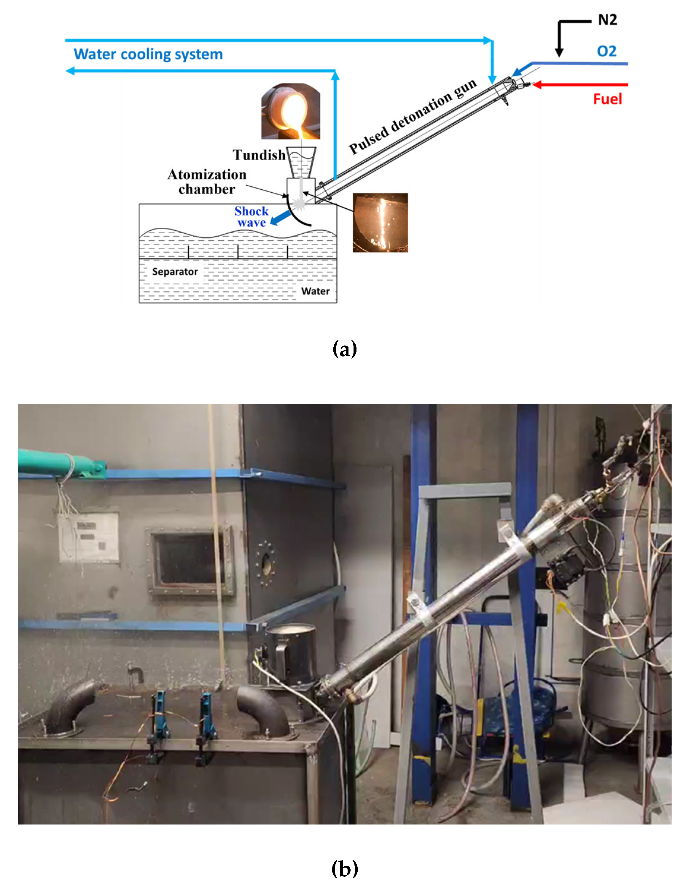
Figure 2.
Samples of aluminum powder: (a) on separator trays and (b) after its collection and drying.
Figure 2.
Samples of aluminum powder: (a) on separator trays and (b) after its collection and drying.
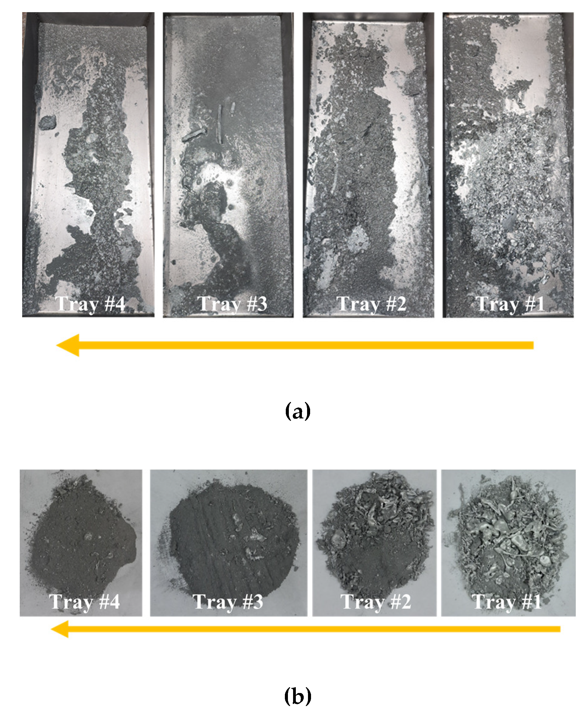
Figure 3.
Example of IP records in a single operation cycle during PDG operation in the frequency mode.
Figure 3.
Example of IP records in a single operation cycle during PDG operation in the frequency mode.

Figure 4.
PMSDs of zinc powder particles in separator trays #1–#4 obtained by means of dry sifting on sieves on fractions 140–250, 70–140, 30–70, and 0–30 μm; sample mass 313.8 g.
Figure 4.
PMSDs of zinc powder particles in separator trays #1–#4 obtained by means of dry sifting on sieves on fractions 140–250, 70–140, 30–70, and 0–30 μm; sample mass 313.8 g.
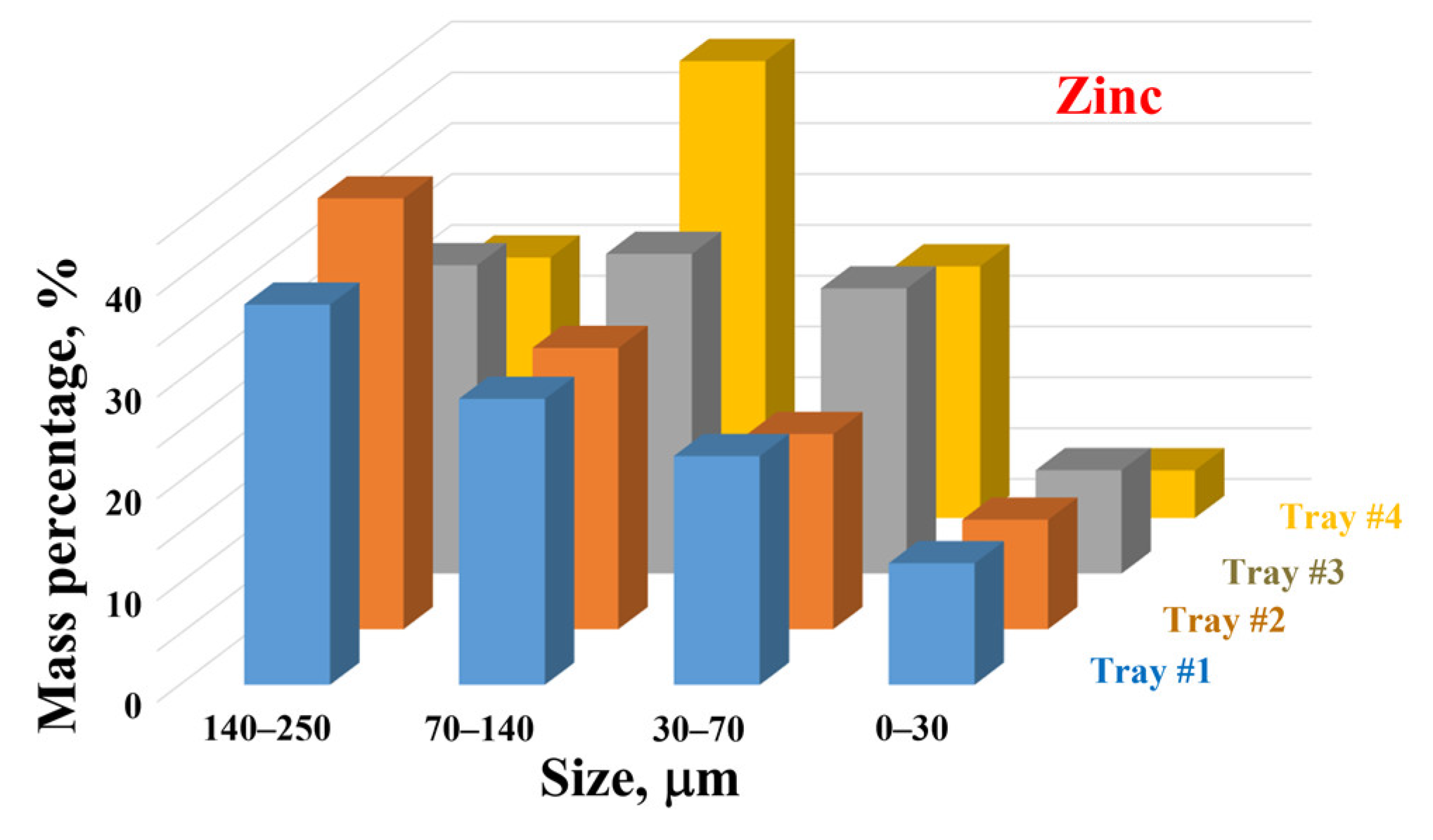
Figure 5.
Results of microscopic and AFM examination of zinc powder fractions (a) 140–250 µm, and (b), (c) 0–30 µm.
Figure 5.
Results of microscopic and AFM examination of zinc powder fractions (a) 140–250 µm, and (b), (c) 0–30 µm.
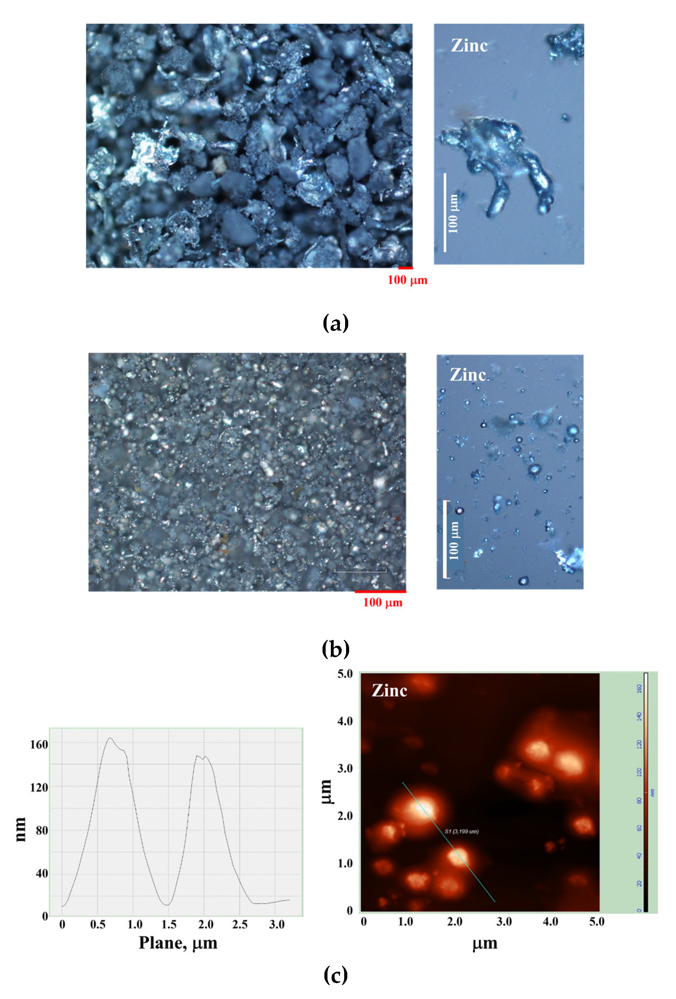
Figure 6.
Zinc powder PSDs obtained by the laser diffraction WDM for several particle fractions: (1) 0–30 µm, (2) 30–70 µm, and (3) 70–140 µm.
Figure 6.
Zinc powder PSDs obtained by the laser diffraction WDM for several particle fractions: (1) 0–30 µm, (2) 30–70 µm, and (3) 70–140 µm.
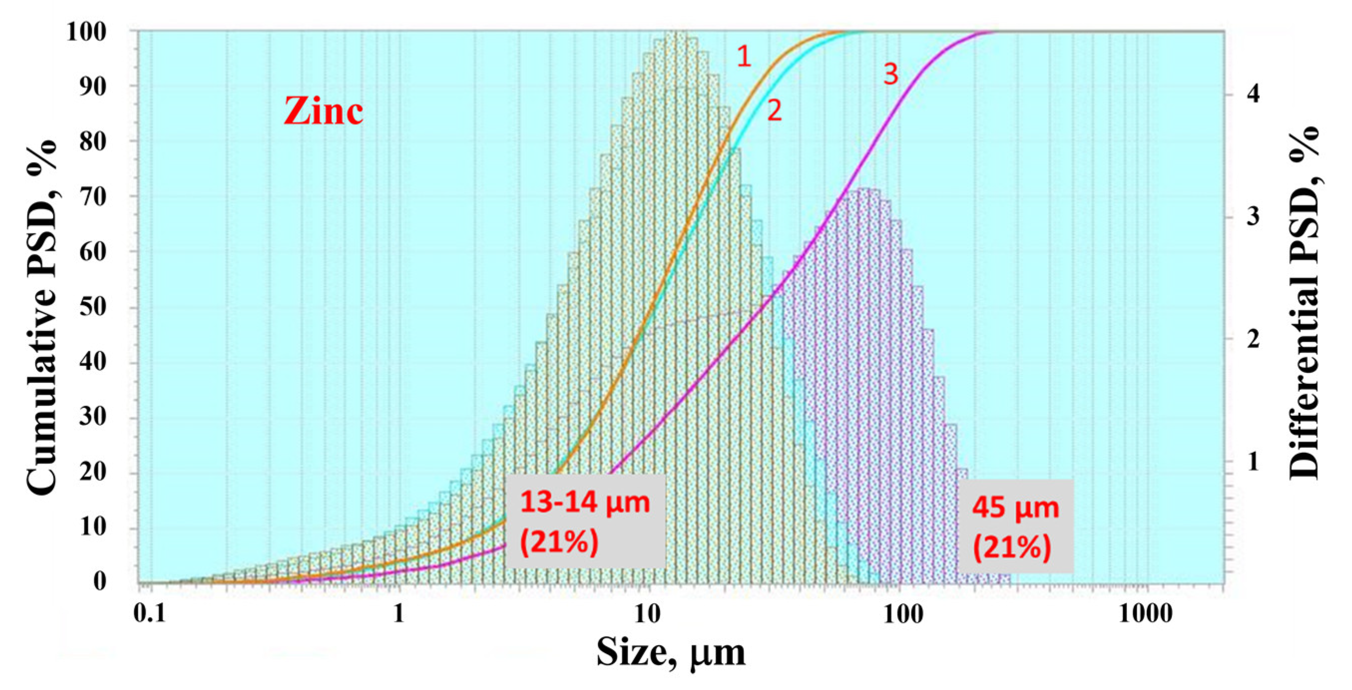
Figure 7.
PMSDs of aluminum powder particles in separator trays #1–#4 obtained by means of dry sifting on sieves on fractions 140–250, 70–140, 30–70, and 0–30 μm; sample mass 143.2 g.
Figure 7.
PMSDs of aluminum powder particles in separator trays #1–#4 obtained by means of dry sifting on sieves on fractions 140–250, 70–140, 30–70, and 0–30 μm; sample mass 143.2 g.
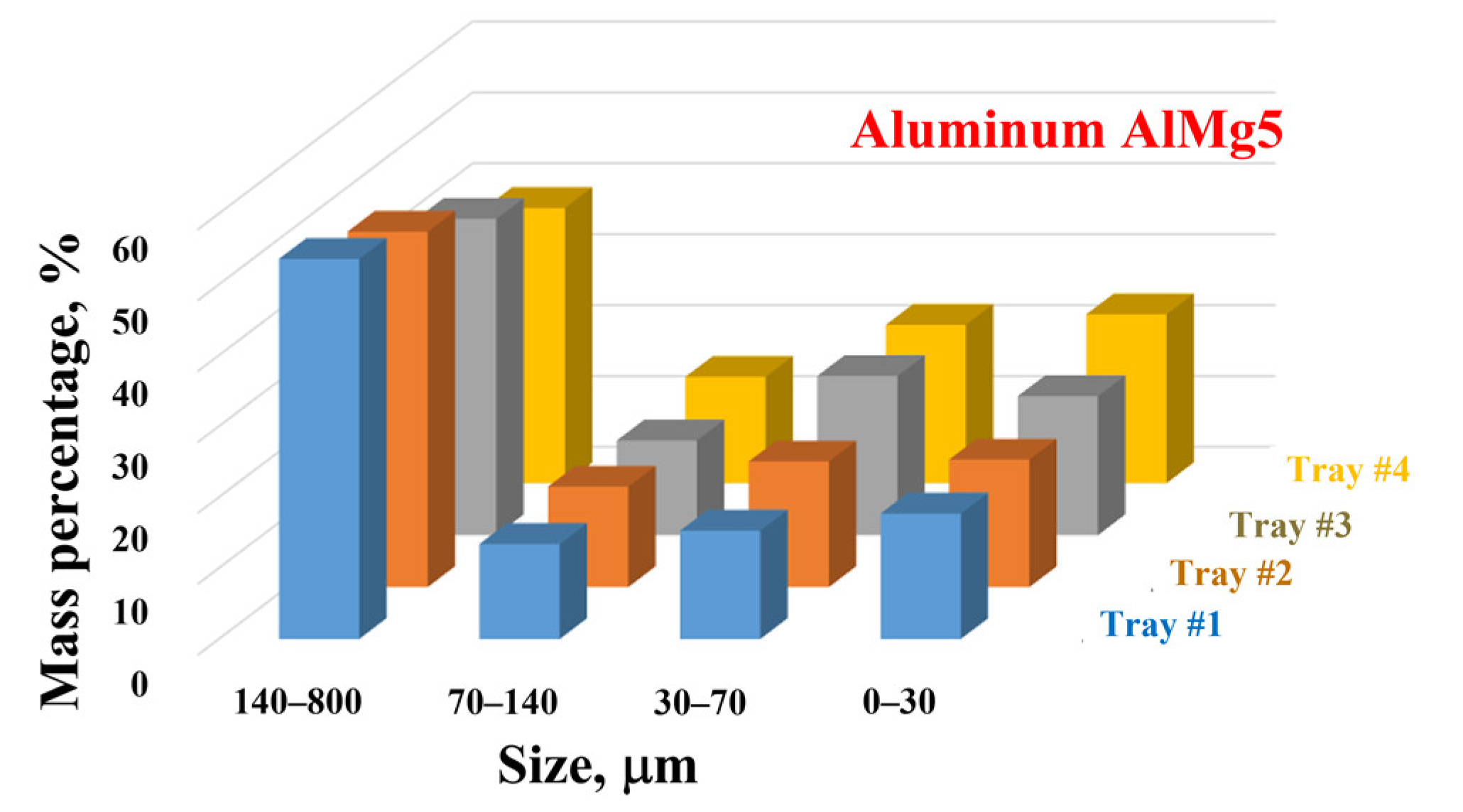
Figure 8.
Results of microscopic and AFM examination of aluminum powder fractions (a) 140–800 µm, and (b), (c) 0–30 µm.
Figure 8.
Results of microscopic and AFM examination of aluminum powder fractions (a) 140–800 µm, and (b), (c) 0–30 µm.
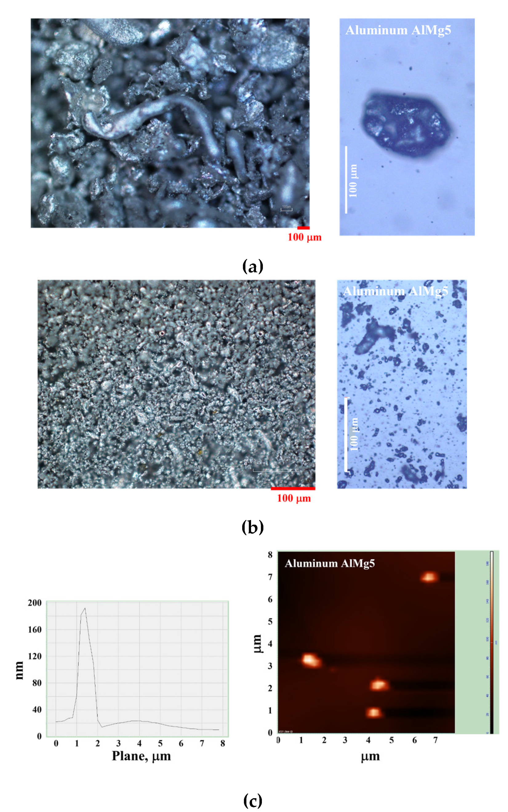
Figure 9.
Aluminum powder PSDs obtained by the laser diffraction WDM for several particle fractions: (1) 0–30 µm, (2) 30–70 µm, and (3) 70–140 µm.
Figure 9.
Aluminum powder PSDs obtained by the laser diffraction WDM for several particle fractions: (1) 0–30 µm, (2) 30–70 µm, and (3) 70–140 µm.
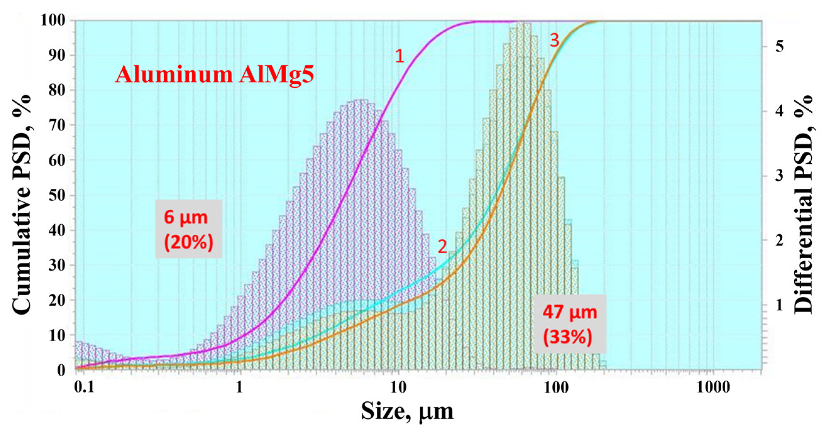
Figure 10.
Sequential video frames of the shock-induced atomization process of the free-falling stream of stainless-steel melt.
Figure 10.
Sequential video frames of the shock-induced atomization process of the free-falling stream of stainless-steel melt.
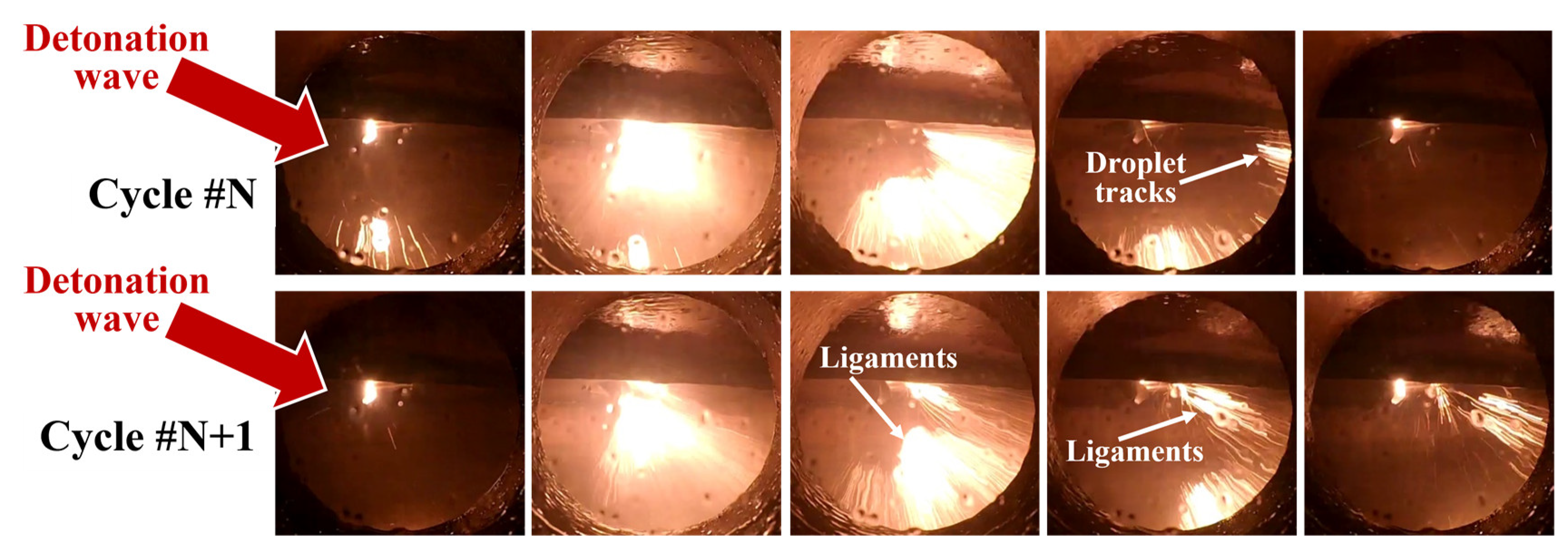
Figure 11.
PMSDs of stainless-steel powder particles obtained by means of dry sifting on sieves on fractions >1000, 800–1000, 400–800, 250–400,140–250, 70–140, 30–70, and 0–30 μm; sample weight 84.4 g.
Figure 11.
PMSDs of stainless-steel powder particles obtained by means of dry sifting on sieves on fractions >1000, 800–1000, 400–800, 250–400,140–250, 70–140, 30–70, and 0–30 μm; sample weight 84.4 g.
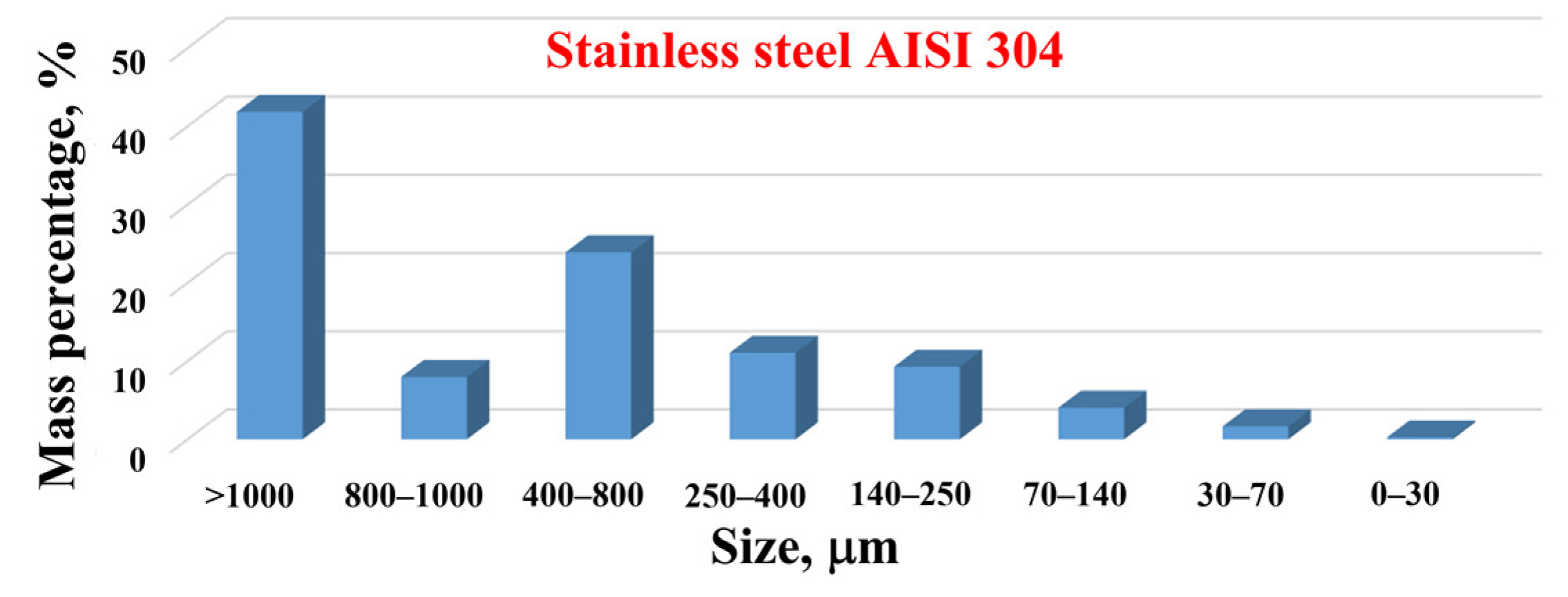
Figure 12.
Results of microscopic and AFM examination of stainless-steel powder obtained on sieves (a) 70–140 µm, and (b), (c) 0–30 µm.
Figure 12.
Results of microscopic and AFM examination of stainless-steel powder obtained on sieves (a) 70–140 µm, and (b), (c) 0–30 µm.
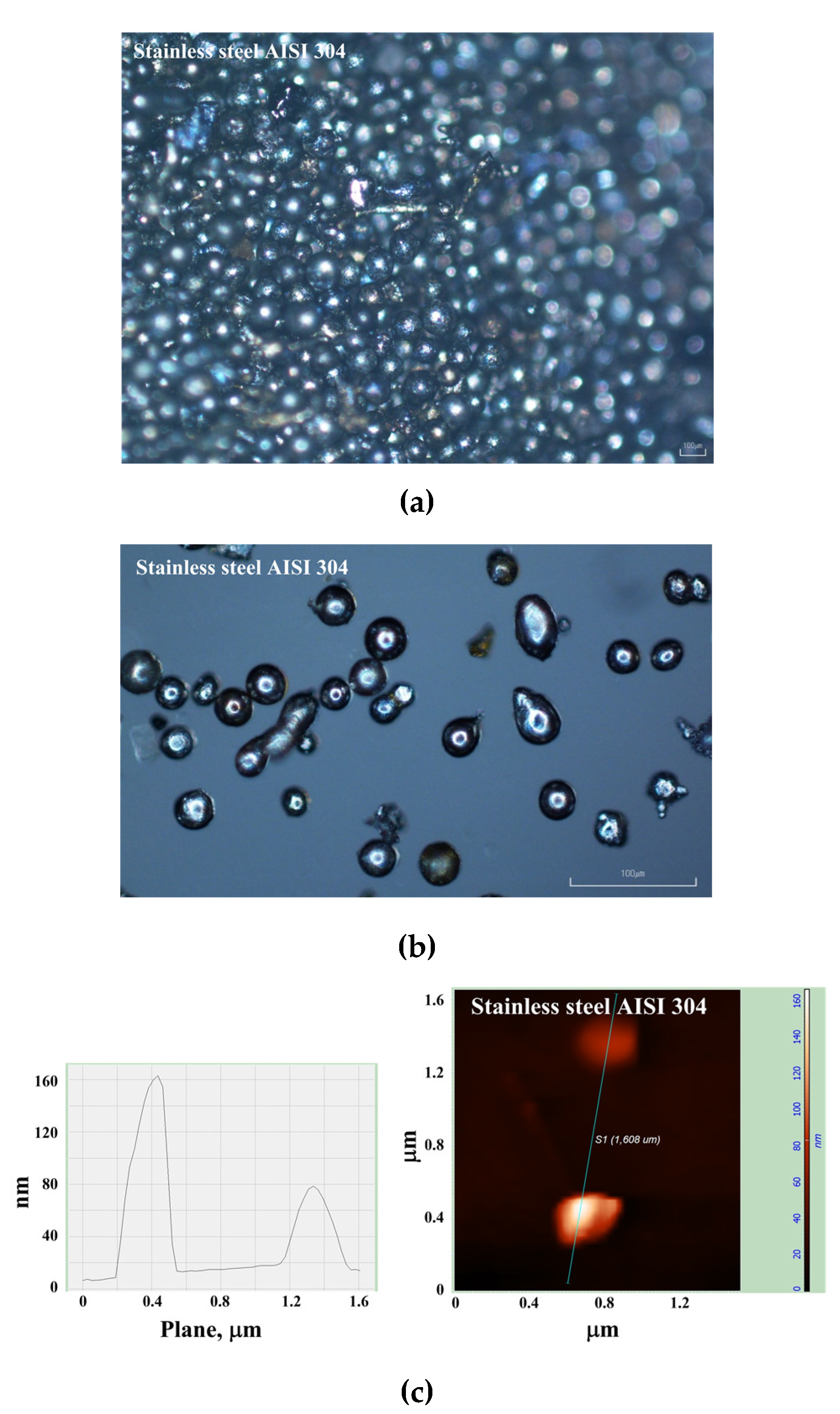
Figure 13.
Stainless-steel powder PSDs obtained by the laser diffraction WDM for several particle fractions: (1) 30–70 µm, (2) 70–140 µm, and (3) 140–250 µm.
Figure 13.
Stainless-steel powder PSDs obtained by the laser diffraction WDM for several particle fractions: (1) 30–70 µm, (2) 70–140 µm, and (3) 140–250 µm.
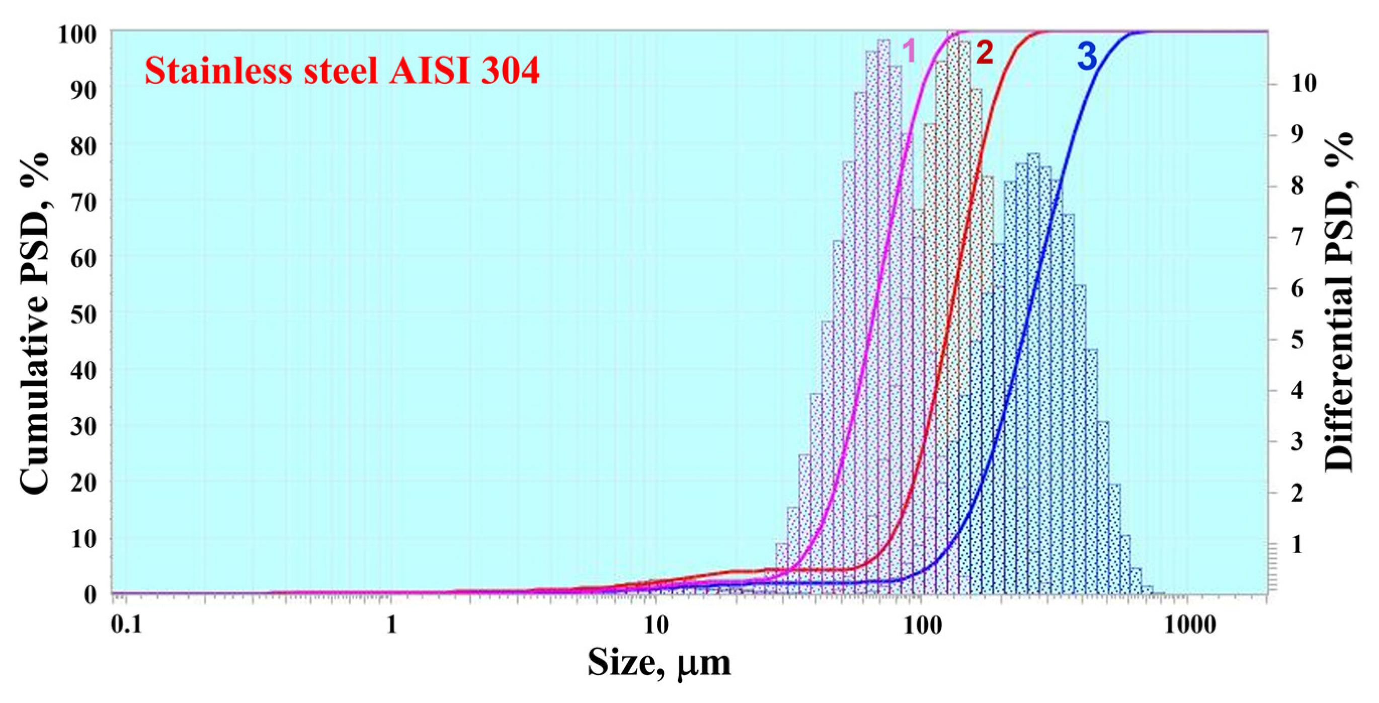
Figure 14.
Comparison of PSDs obtained by the laser diffraction WDM for aluminum and zinc powders of fraction 0–30 µm.
Figure 14.
Comparison of PSDs obtained by the laser diffraction WDM for aluminum and zinc powders of fraction 0–30 µm.
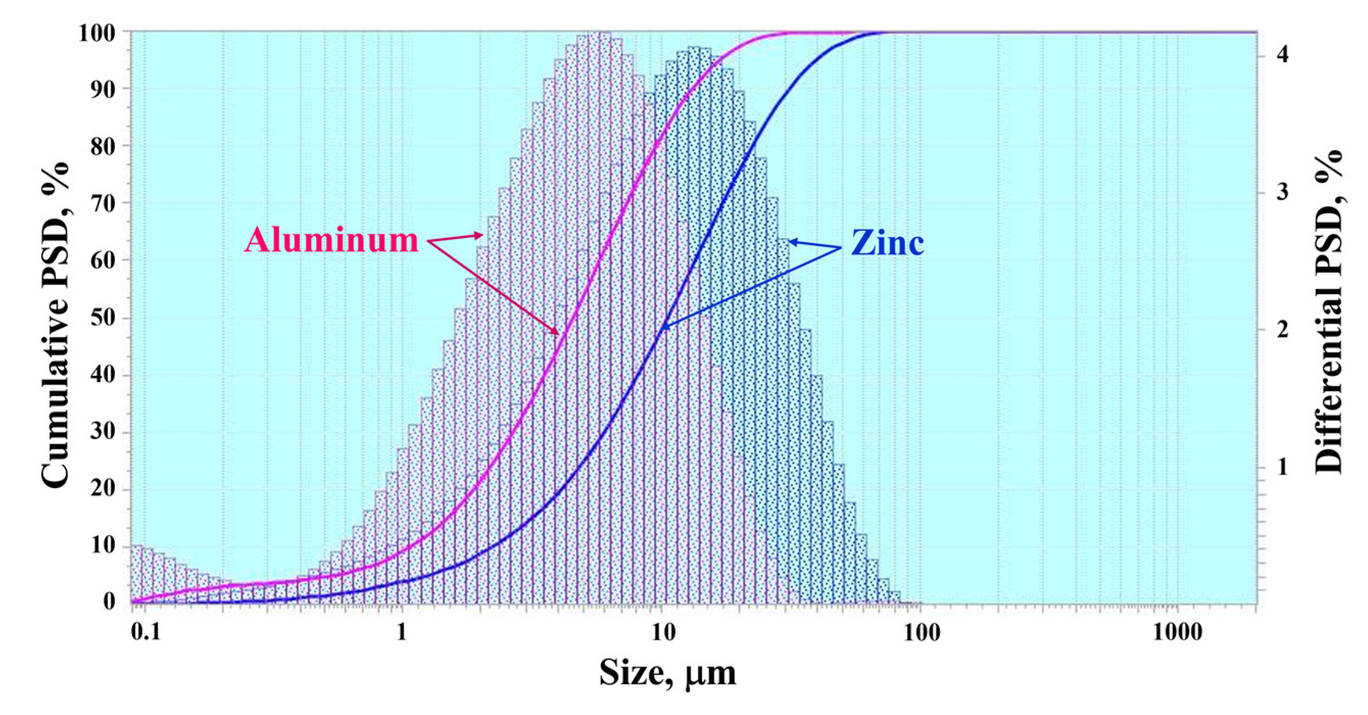
Figure 15.
Comparison of PSDs obtained by the laser diffraction WDM for zinc, aluminum, and stainless-steel powders of fraction 30–70 µm.
Figure 15.
Comparison of PSDs obtained by the laser diffraction WDM for zinc, aluminum, and stainless-steel powders of fraction 30–70 µm.
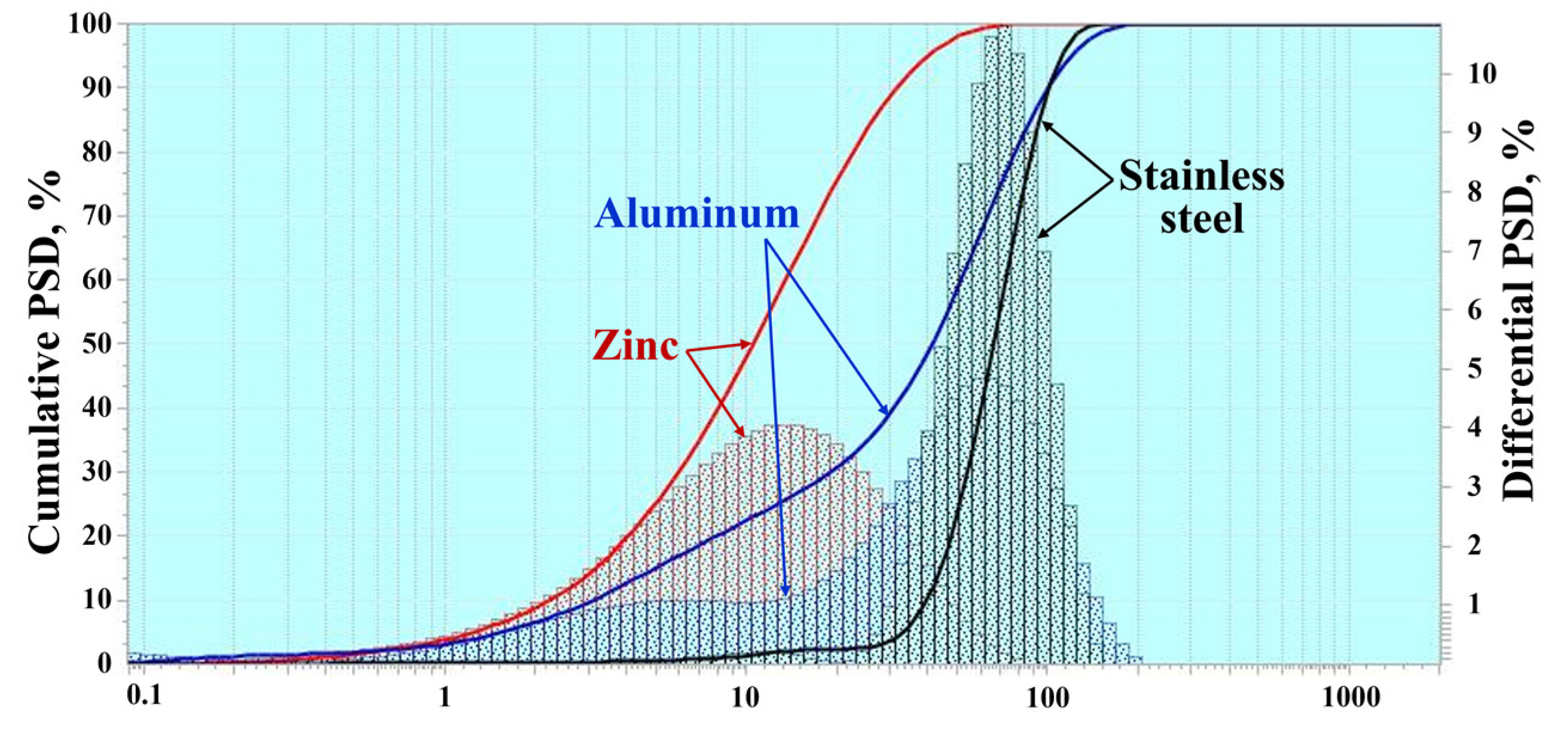

Table 1.
Studied metals.
| Metal | Purity/Composition |
| Zinc | 99,9% |
| Aluminum alloy AlMg5 | Аl (92–95%), Mg (5–6%), Mn (up to 0.8%) |
| Stainless steel AISI 304 | Fe(66–74%), Cr (17.5–20%), Ni (8–11%) |
Table 2.
Properties of studied metals.
| Metal | Density, kg/m3 |
Melting temperature, °C |
Boiling temperature, °C |
Melt surface tension, N/m |
Melt viscosity, mPa∙s |
|---|---|---|---|---|---|
| Zinc | 7100 | 420 | 906 | 0.78 | 2.1 |
| Aluminum alloy | 2700 | 660 | 2519 | 0.88 | 1.3 |
| Stainless steel AISI 304 | 7900 | 1400 | 2900–3200 | 1.7 | 6.0 |
Table 3.
Composition of the liquid hydrocarbon fuel.
| Compound | Content, vol.% |
| Heptane isomers | 71 |
| Methylcyclohexane | 14 |
| Cyclohexane | 8 |
| Hexane isomers | 4 |
| Octane isomers | 3 |
Table 4.
Properties of the liquid hydrocarbon fuel.
| Property | Value |
| Density at 20 °C | 0.700 kg/m3 |
| Flash Temperature [Method] | –9 °C [ASTM D-56] |
| Flammability limits (vol.% in air) | Lower flammability limit 0.8; Upper flammability limit 7.7 |
| Self-ignition temperature, °C | >200 °С |
| Boiling temperature, °C | 78–113 |
| Vapor pressure (air = 1 at 101 kPa) | > 1 |
| Saturated vapor pressure, kPa | 6.1 kPa at 20 °С; 14.5 kPa at 38°С; 23.1 kPa at 50 °С |
| Evaporation rate (n-buthylacetate = 1): | 3 |
| Kinematic viscosity | 0.49 mm2/s at 40 °С; 0.67 mm2/s at 25°С |
| Freezing temperature, °С | < –40 °С |
| Molecular mass, a.u. | Calc. 98 |
Table 5.
Measured and calculated detonation velocity and calculated composition of detonation products expanded to 1 bar.
Table 5.
Measured and calculated detonation velocity and calculated composition of detonation products expanded to 1 bar.
|
, m/s |
a, m/s |
a, K |
H2O b, vol.% |
CO2, vol.% |
CO, vol.% |
O2, vol.% |
H2, vol.% |
Other, vol.% |
| 2100 | 2342 | 2811 | 36.1 | 22.3 | 17.7 | 8.7 | 4.1 | 11.1 |
Disclaimer/Publisher’s Note: The statements, opinions and data contained in all publications are solely those of the individual author(s) and contributor(s) and not of MDPI and/or the editor(s). MDPI and/or the editor(s) disclaim responsibility for any injury to people or property resulting from any ideas, methods, instructions or products referred to in the content. |
© 2024 by the authors. Licensee MDPI, Basel, Switzerland. This article is an open access article distributed under the terms and conditions of the Creative Commons Attribution (CC BY) license (http://creativecommons.org/licenses/by/4.0/).
Copyright: This open access article is published under a Creative Commons CC BY 4.0 license, which permit the free download, distribution, and reuse, provided that the author and preprint are cited in any reuse.


