
Submitted:
25 November 2024
Posted:
27 November 2024
You are already at the latest version
Abstract
Ultrasound micromolding (USM) is an emerging processing technology that offers advantages concerning spatial resolution, material saving, minimum time residence, minimum exposition to high temperatures and low cost. Recent advances have been focused to the point nodal tech-nology, which improves the homogeneity of the molded samples and the repeatability of the properties of processed specimens. The present work demonstrates the suitability of the modi-fied USM technology to process the biodegradable poly(3-hydroxybutyrate) (P3HB), which is a polymer that has well reported difficulties to be processed by conventional methods. Specifical-ly, conventional injection and microinjection, and USM technologies with and without point nodal configurations have been compared. Degradation studies and the evaluation of thermal and mechanical properties confirmed the successful preparation of P3HB micro-specimens, maintaining their functional integrity with minimal molecular weight loss. Exfoliated clay structures were observed for P3HB nanocomposites incorporating the C20 and C166 clays and processed by USM. The results point out the advantages of using the modified USM technology since C116 enhanced the P3HB degradation and consequently processed specimens were impos-sible to be obtained by conventional microinjection.
Keywords:
ultrasound micromolding
; point nodal technology
; poly(3-hydroxybutyrate)
; clay nanocomposites
1. Introduction
Poly(3-hydroxybutyrate) (P3HB) is a member of the polyhydroxyalkanoate family, distinguished by its short side chain. P3HB has attracted significant attention for its potential in biomedical and packaging applications. As a bio-based polymer, it is primarily produced through bacterial fermentation by Ralstonia eutropha using carbon source rich in propionate [1]. Although the 3-hydroxybutyrate (3HB) unit has a chiral center, bacteria produce only one optically active form, resulting in highly crystalline polymer, typically exceeding 50% crystallinity [2]. P3HB has a glass transition temperature around 10 ºC and mechanical properties similar to those of polyethylene and polyethylene terephthalate, though it is more hydrophilic [3]. Key advantages of P3HB include ease of production, low cost, biodegradability, and biocompatibility, making it attractive for material development. However, its high crystallinity leads to limitations such as stiffness, slow degradation, and low flexibility due to aging-induced recrystallization [4,5,6,7]. Additionally, P3HB exhibits a high melting temperature of around 170 ºC, which is unfortunately very close to its thermal decomposition temperature. Studies have shown that the polymer experiences a 2% weight loss at 223 ºC and a 95% weight loss after an 8-hour treatment at 160 ºC [8,9]. This characteristic makes P3HB challenging to process in its molten state, such as when using typical twin-screw extruders, due to the significant thermal degradation caused by the high temperatures, shear stress, and pressure over extended periods. Consequently, the polymer has a limited processing window, restricting its application and making it difficult to meet many industrial demands. Efforts to address these processing challenges have included the addition of plasticizers, structural modifications of the polymer, and blending with other materials [10,11,12].
Material properties can be significantly enhanced by incorporating nanoclays, which form intercalated or exfoliated structures [13]. To improve their compatibility with hydrophobic polymers, these nanoclays are often modified with organic compounds, such as quaternary ammonium salts, which act as effective surfactants [14,15]. However, in P3HB nanocomposites, the use of quaternary ammonium salts can be problematic, as they may lead to increased thermal degradation under typical preparation conditions (i.e., molten state and elevated temperatures) [15].
Alternatively, several studies have demonstrated a positive impact of certain nanoclays on P3HB properties. For instance, montmorillonites modified with tributylhexadecylphosphonium bromide have been shown to form intercalated structures through both casting and extrusion processes, effectively slowing the degradation rate [13]. P3HB nanocomposites with Cloisite 30B exhibited a reduction in both glass transition temperature (by 7 ºC) and melting temperature (by 15 ºC) at a 3% weight clay content. Additionally, there was a slight increase in crystallinity (by 3%) and a significant rise in degradation temperature (by 11 ºC) [15,16]. These findings suggest that the intercalated clay acts as a plasticizer, enhancing processability by increasing the temperature gap between melting and decomposition.
High-power ultrasound waves have recently been demonstrated as an efficient technology for producing micro-molded specimens [17]. Ultrasound has previously been employed to facilitate conventional injection and extrusion processes, as well as to serve as a welding method for polymers [18,19,20]. Ultrasonic micromolding (USM), though still in the development phase for industrial applications, shows promise as an alternative to conventional microinjection techniques. This emerging molding process offers significant advantages for industries such as biomedical, electronics, and telecommunications [21,22].
One of the key advantages of USM is its extremely short processing time, which minimizes thermal degradation by reducing the residence time during the process. Additionally, ultrasound waves lower the polymer viscosity, allowing the material to flow at lower temperatures. USM also provides high spatial resolution, energy savings, and reduced material loss in the sprues and plasticizing chamber [21].
USM has proven effective for processing various polymers, including polylactide [19], polypropylene [23,24], and polyamides [25], with minimal molecular weight loss and degradation. Furthermore, polymer matrices can be uniformly loaded with pharmacological compounds, carbon nanotubes, and glass nanoparticles [18]. However, care must be taken to minimize degradation depending on the polymer matrix and the functional groups of the selected drug. Interestingly, USM can also achieve homogeneous dispersions in clay nanocomposites. In some cases, exfoliated structures can be obtained using pristine clay, eliminating the need for organic modification [17].
The present work has two main objectives aimed at improving the processing of P3HB. First, the applicability of ultrasonic micromolding (USM) for producing P3HB micromolded specimens is explored. It is expected that minimal polymer degradation will occur due to the short residence time at high temperatures, the unique heating process of USM, and the ease of melt flow. Second, the study examines the preparation of P3HB-based nanocomposites. The incorporation of clays is anticipated to facilitate processing, as previously mentioned, while also enhancing certain material properties.
2. Materials and Methods
2.1. Materials
The P3HB sample used in this study is a commercial product (P304) supplied by Biomer (Krailling, Germany), with a reported crystallinity of approximately 60-70%. When molten P3HB cools, it undergoes a rapid crystallization step at around 120 ºC, followed by a slower crystallization phase between 110 ºC and 60 ºC.
Two different nanoclays were investigated: Cloisite 116, a natural bentonite, and Cloisite 20, a natural montmorillonite modified with dimethyl dihydrogenated tallow quaternary ammonium cations. Both clays were provided by BYK Chemie GmbH (Wesel, Germany) and were used as received. The nanocomposites are designated by abbreviations indicating the polymer type, the weight percentage of the added nanoclay, and the nanoclay type. For example, P3HB5C20 refers to a P3HB nanocomposite containing 5 wt% of Cloisite 20.
2.2. Compounding Extrusion of P3HB for Nanocomposite Preparation
A conventional co-rotating twin-screw extruder (ZSK 18 MEGAlab from Coperion) was used to produce the nanocomposites. This equipment features an outer diameter (Da) of 18 mm and a Do/Di ratio of 1.55, with two co-rotating screws designed to enhance the dispersion of fillers and additives. The extruder has seven temperature-controlled zones. The nanocomposites were produced using a decreasing temperature profile of 175/175/170/170/165/160/160 ºC, with a throughput of 7 kg/h and a Specific Mechanical Energy (SME) of 150 kJ/kg applied to the material.
2.3. Conventional Microinjection
To produce the dumbbell samples for conventional microinjection, a standard Arburg Allrounder 170 U was utilized. This equipment has a clamping force of 150 kN and is equipped with an 18 mm diameter screw. The temperature profile within the injection unit was 180/170/160 ºC, with a mold temperature of 60 ºC and a cooling time of 15 seconds. The dimensions of these dumbbell samples were 3.5 cm × 0.6 cm × 0.1 cm, with the tested zone measuring 1.2 cm × 0.2 cm × 0.1 cm.
2.4. Ultrasonic Micromolding
In the present work, the newly developed Sonorus 2G® ultrasonic micromolding (USM) equipment (Ultrasion S.L., Barcelona, Spain) was employed (Figure 1a), which represents a substantial advancement over earlier USM prototypes. This latest model introduces two critical innovations that enhance both the efficiency and quality of the molding process:
- Robust clamping unit: The Sonorus 2G® is equipped with a robust clamping unit that can exert up to 150 kN of force, significantly reducing the occurrence of burrs, which was a common issue in previous designs. This feature ensures cleaner and more precise moldings.
- Nodal point ultrasonic molding configuration: The Sonorus 2G® integrates a nodal point configuration that strategically aligns the sonotrode nodal point (where longitudinal amplitude is zero), with the mold feeding channel. This innovative alignment optimizes the transmission and focus of ultrasonic energy, thereby enhancing the precision and stability of the molding process.
The operational sequence of the Sonorus 2G® involves four steps as illustrated in Figure 1b. Initially, polymer pellets are efficiently fed through the parting line at the beginning of each cycle during the Feeding stage. In the Melting/Injection stage, an additional plunger compacts polymer pellets against the sonotrode, which is precisely sealed by the enhanced design of the plasticizing chamber, ensuring effective material handling and energy utilization. Following this, the Cooling process allows the specimen to remain within the mold under controlled temperatures, preventing deformation and preserving the integrity of the molded specimen. Finally, in the Ejection stage, the specimen is smoothly ejected by an advanced plunger and ejector system, which is designed for ease and reliability, facilitating the removal of the final product without damage.
2.2. Measurements
Molecular weight was estimated using size exclusion chromatography (GPC) with a Shimadzu liquid chromatograph (model LC-8A, Tokyo, Japan) and analyzed using the Empower software (Waters, Milfold, MA, USA). The polymer was dissolved and diluted in 1,1,1,3,3,3-hexafluoroisopropanol (HFIP) containing 0.05 M CH3COONa. The flow rate was set to 1 mL/min, with an injection volume of 20 µL and a sample concentration of 2 mg/mL. A PL HFIP gel column (Polymer Lab, Agilent Technologies Deutschland GmbH, Böblingen, Germany) and a Shimadzu RID-10A refractive index detector were used. Number and weight average molecular weights were determined using polymethyl methacrylate standards.
Infrared absorption spectra were recorded at a resolution of 4 cm−1 using a Jasco Fourier transform FTIR 4100 spectrometer (Jasco, Tokyo, Japan). The measurements employed a Specac MKII Golden Gate Single Reflection Diamond ATR system (Specac, Orpington, Kent, UK), which is operational up to 200 ºC, along with a high stability 4000 series controller.
A Focused Ion Beam Zeiss Neon40 microscope (Zeiss, Oberkochen, Germany) operating at 5 kV was used to obtain SEM micrographs of micromolded specimens. Samples were mounted on a double-sided adhesive carbon discs and sputter-coated with a thin layer of carbon using a Mitec K950 Sputter Coater (Quorum Technologies Ltd., Ashford, UK).
Tensile deformation tests were conducted using a Zwick Roell Z050 Universal Tester (Barcelona, Spain), equipped with a 500 N load cell and testXpert 8.1 software (Zwick, Ulm, Germany), following UNE EN 527 standards at a velocity of 50 mm/min. Five specimens were tested for each processing condition.
Calorimetric data were recorded using differential scanning calorimetry (DSC) with a TA Instruments Q20 series device (New Castle, DE, USA), equipped with a cooling system operating from −40 to 400 ºC. The experiments were conducted under a flow of dry nitrogen with samples of approximately 3 mg. The instrument was calibrated for temperature and heat of fusion using an indium standard. Tzero technology required two calibrations: one with empty pans and another with sapphire discs. The thermal characterization of the polymers followed a three-step protocol: an initial heating run of the as-molded sample, a cooling run after holding the sample in the melt for 1 minute, and a second heating run of the non-isothermally crystallized sample. All scans were performed at a rate of 10 ºC/min.
Thermogravimetric analysis (TGA) and differential thermogravimetric analysis (DTGA) data were acquired using a TA Instruments Q50 thermogravimetric analyzer (New Castle, DE, USA). Studies were conducted under a flow of dry nitrogen with approximately 5 mg samples and a heating rate of 20 ºC/min.
The structure of the processed specimens, specifically the spacing between layers of nanoclays within the polymer, was analyzed using Wide-Angle X-ray Diffraction (WAXD). A Bruker D8 Advance model with Cu Kα radiation (λ=0.1548 nm) and Bragg-Brentano geometry (theta-2theta) was utilized. A one-dimensional Lynx Eye detector was employed. The samples were processed at 40 kV and 40 mA, with a 2-theta range of 2° to 40°. Measurements were taken in steps of 0.02°, and a time per step ranging from 2 to 8 seconds.
The distribution of Cloisite 20 and Cloisite 116 within the polymer matrix was further examined using a Philips TECNAI 10 electron microscope (Philips Electron Optics, Eindhoven, Netherlands) at an acceleration voltage of 100 kV. Thin sections of the samples were prepared using a Sorvall Porter-Blum microtome (Sorvall, New York, USA) equipped with a diamond knife. The sections were collected in a container filled with water and then lifted onto copper wire racks coated with carbon.
3. Results and Discussion
3.1. Optimization of USM Processing Parameters
The optimal processing window for ultrasonic micromolding (USM) was determined by two key parameters: plunger velocity and ultrasonic amplitude. These optimal values were identified through a design of experiments. The mold temperature was maintained at 60 ºC according to recommendations from material provider. Various combinations of these parameters were tested while recording temperature and pressure during the filling step.
Initially, the goal was to achieve fully formed pieces. Any conditions that failed to produce these filled samples were immediately discarded. Next, conditions that resulted in visible material degradation were rejected based on simple visual inspection. The repeatability of the process was a crucial factor in eliminating certain parameter combinations. Finally, the recorded temperature and pressure, measured by sensors placed in the mold cavity, were used to evaluate both repeatability and the most suitable processing conditions.
Four optimal combinations of amplitude and plunger velocity were identified. These conditions were evaluated for both the neat polymer and a selected nanocomposite containing 5% Cloisite 20. Table 1 presents the various optimized sets and the related mechanical properties of the specimens, such as tensile strength (TS) and elongation at break (Eb), along with the recorded temperature and pressure in the mold. The results clearly demonstrate that mechanical performance can be significantly enhanced by precisely controlling parameters like amplitude and plunger velocity.
The different processing conditions were then compared to select the optimal one from a mechanical standpoint. The condition of 36% amplitude and 2.5 mm/s plunger velocity was selected for both the neat polymer and the nanocomposite. This optimal condition was also found suitable when the nanoclay content varied from 3 wt% to 8 wt% and even when Cloisite 116 was used instead of Cloisite 20.
Table 1 clearly demonstrates that the mechanical performance of each test condition varied significantly based on the amplitude and plunger velocity applied, which directly influence the temperature and pressure at the sonotrode. The optimal conditions are identified as those yielding the highest tensile strength and the least variability, as indicated by low standard deviations. Specifically, test condition 3 emerged as the optimal condition for P3HB, showing the highest tensile strength and elongation at break. Additionally, the injection temperature detected for each specimen was relatively stable, with a standard deviation of 14.5 ºC, the lowest among the four injection condition groups for P3HB. For P3HB with 5% Cloisite 20, test condition 7 emerged as the optimized condition.
In contrast, with conventional microinjection, where the specimen size is significantly larger than those produced by USM, the optimization of conditions can be effectively determined through visual assessment. The injection parameters, such as temperature, pressure, and cooling time, are adjusted until the product meets specific quality standards, such as smooth surfaces, perfect form, and absence of defects like burrs. Therefore, the detailed optimization process for conventional microinjection is not shown.
3.2. Molecular Weight
GPC measurements provided valuable insights into how ultrasonic parameters such as energy/wave amplitude, plunger velocity, and switchover force (a parameter related to residence time) influence the molecular weight of materials. Figure 2 displays three representative chromatographs: one from the initial pellet, one from a specimen processed under optimal conditions, and one from a specimen showing clear signs of degradation. According to the result, P3HB can be processed with minimal loss in molecular weight through USM. Table 2 presents a comparison of data from samples processed under varying conditions, illustrating the stability of molecular characteristics across different processing settings.
3.3. Chemical Characterization: FTIR
The FTIR spectra of the P3HB raw material (extruded pellets) were analyzed and compared to those obtained from samples produced through conventional microinjection and ultrasonic micromolding (USM) under both optimal and non-optimal conditions. Figure 3 illustrates the characteristic P3HB bands present in all samples, including CH2 at 2974 cm-1 and 2933 cm-1, C=O at 1719 cm-1, and -C-O at 1277 cm-1 and 1054 cm-1. The spectra were largely consistent across different samples, except for that produced with non-optimal USM parameters. This sample showed signs of degradation, as indicated by the distinct splitting of the C=O band and variations in the intensity of bands around 1200 cm-1, highlighted by a black ellipsoid in the Figure 3.
3.4. Chemical Characterization: NMR
The comparison of the 13C-NMR and 1H-NMR spectra for PHB before and after processing through both conventional microinjection and USM technology under optimized conditions revealed no significant differences. This was observed in both the 1H-NMR spectra (Figure 4a) and 13C-NMR spectra (Figure 4b), suggesting that there is no appreciable degradation across both processing techniques. The observed peaks are consistent with those reported in various literature sources [26,27,28,29].
In the 1H-NMR spectra (Figure 4a), three distinct types of peaks were noted: a doublet at δ 1.26-1.28 ppm, which corresponds to protons in the methyl side chain; a multiplet at δ 5.22-5.30 ppm, associated with protons of the CH group near the oxygen atom; and a complex peak at δ 2.44-2.63 ppm, which represents a doublet of a quadruplet from a -CH2- group. The presence of a quadruplet suggests that methyl side chain is close to the -CH2 group, indicating a very compact molecular structure.
For the 13C-NMR spectra (Figure 4b), four key carbon peaks were identified: at δ 169 ppm for the carbonyl carbon, δ 67 ppm for carbon linked to oxygen, δ 41 ppm for -CH2-, and δ 20 ppm for the carbon in the methyl side chain. Like 1H-NMR results, these peaks showed no variations, reinforcing the stability of the material structure under the processing conditions used. Based on GPC results, it was expected that some minor peaks associated to terminal groups would appear near 170 ppm for conventional injection samples as it showed a molecular weight reduction of approximately 17,000 g/mol compared to the raw material. However, no such peak was detected in 13C-NMR spectra. This absence suggests that, although molecular weight reduction occurred, its ratio was still low to be detected.
3.5. Geometry and Morphology of Processed Specimens
Figure 5 displays the shapes of specimens fabricated using conventional microinjection and USM technology, both utilizing the same configurable mold. In each method, the samples appeared uniform with smooth surfaces. No significant macroscopic defects, such as pores, were noted in the cross-sections. However, the cross-section of the USM specimen exhibited a more uniform surface. High-magnification SEM micrographs of the USM-processed P3HB specimens revealed spherulitic aggregates with radial lamellae (see dashed ellipsoid in Figure 5c). Such crystalline structures were absent in the specimens produced via conventional microinjection, pointing to differences in the cooling processes.
3.6. X-Ray Diffraction Patterns of P3HB Processed Samples
The X-ray diffraction profiles of the processed samples matched the known crystalline structure of P3HB in its α-form, which is characterized by an orthorhombic unit cell with parameters a = 0.576 nm, b = 1.320 nm, and c = 0.596 nm. This structure belongs to the P212121 space group and exhibits a TḠḠT molecular conformation [30]. The main peaks, corresponding to the 020 and 110 reflections, were observed at 0.660 nm and 0.445 nm, respectively (Figure 6a). The structure is stabilized through intermolecular hydrogen bonding between the C=O and CH3 groups of adjacent chains along the a-axis. Additionally, a planar zig-zag conformation, known as the β-form, has been identified in samples subjected to stretching, distinguishable by reflections at 0.480 nm and 0.460 nm. However, no traces of these reflections were found in the diffraction patterns of the processed samples.
Variations between diffraction profiles were minimal due to their similar and high crystallinity, as later confirmed by DSC analysis. Nevertheless, variations in peak sharpness, attributable to differences in the size of crystalline domains, were noted. This effect was more pronounced in the q range (i.e., q = 2π/d, with d representing the Bragg spacing) from 14 nm-1 to 18 nm-1 (Figure 6b). The comparison between the profiles of the initial P3HB pellet (the extruded sample) and the USM specimen highlighted a higher crystallinity and crystal size for the former sample. However, it should be considered the aging effect produced during storage of the pellet. In this way, resolution was accentuated when the USM specimen was aged by heating up to 60 ºC.
3.7. Thermal Properties and Crystallinity of Micromolded Specimens
Micromolded specimens produced by both conventional microinjection and ultrasonic micromolding (USM) exhibited similar thermal properties, as shown in Figure 7. During the initial heating run, the main melting peak occurred at approximately 171-172 ºC. Notably, the melting enthalpy for such samples was around 43-44 J/g, indicating a similar degree of crystallinity. This crystallinity was close to 29% as calculated from the reported enthalpy of 143 J/g for a fully crystalline P3HB sample. During the cooling phase, both types of specimens displayed a consistent exothermic peak, with an enthalpy between 42-43 J/g, occurring at temperatures ranging from 115-117 ºC.
The behavior observed in the second heating run differed from the first one, as consequence of different cooling rates of the sample in the mold and within the DSC equipment. Consequently, the temperature of the primary peak slightly decreased, from 171 ºC to 165 ºC, likely due to a reduction in lamellar thickness. Despite this, a small shoulder at around 171 ºC remained visible (see dashed red box in Figure 7). This shoulder could possibly be attributed to a typical reorganization of crystals during the second heating phase.
3.8. USM Processing of P3HB/C20 and P3HB/C116 Nanocomposites. Molecular Weight Distribution
The two types of nanocomposites studied were effectively processed using ultrasonic micromolding (USM) technology for compositions containing 3 wt%, 5 wt%, and 8 wt% of nanoclay, utilizing the same parameters established for the neat polymer. Representative GPC curves are displayed in Figure S1, and detailed data for all compositions are compiled in Table 3. To minimize data dispersion resulting from potential inhomogeneities in the processed samples, specimens were first dissolved in HFIP. Subsequently, aliquots containing 5 mg were evaporated for GPC analysis. Notably, only minimal to moderate variations in molecular weight were observed for the nanocomposites with 3 wt% of C20 and C116 clays, with Mw values decreasing by 5.4% and 23.7%, respectively. The increase in clay content had insignificant effects on the molecular weight for the C20 clay, with Mw values decreasing by 5.4%, 6.3%, and 11.5% for clay contents of 3 wt%, 5 wt%, and 8 wt%, respectively.
Care should be taken with the C116 clay as it has shown significant molecular weight reduction. For instance, Mw decreased by 35.7%, from 135,400 g/mol to 87,000 g/mol, at the highest clay concentration. It is also important to note that a substantial degradation occurred during the initial compounding process. Specifically, Mw was reduced to 97,000 g/mol—a 28% decrease—for extruded pellets that included 8 wt% of C116. Consequently, the ultrasound micromolding process contributed to only an additional 10% reduction in Mw, decreasing from 97,000 g/mol to 87,000 g/mol.
Table 3 also reveals that C20 nanocomposites could be produced with minimal degradation through microinjection, unlike the C116 nanocomposites. It is noteworthy that conventionally microinjected P3HB/C116 specimens were not viable due to significant molecular weight reduction and the compromised flowability of the material as it exited the nozzle, with an Mw of 33,000 g/mol.
A crucial finding is the effectiveness of USM in producing P3HB/C116 nanocomposites across all tested compositions, which was not possible with conventional microinjection. The conventional process failed due to the high temperatures, prolonged residence times, and the narrow feeding channels, which hindered the flow of the polymer melt. In contrast, extrusion of P3HB/C116 was successful, facilitated by the different geometry of the extruder nozzle and the rapid cooling of the extruded material.
3.9. Morphology of P3HB/C20 and P3HB/C116 Nanocomposites
Morphology and distribution of nanoclays within the P3HB matrix were analyzed using both TEM (Figure 8a) and SEM (Figure 8b). TEM analysis of ultrathin sections at various magnifications highlighted the dominant clay morphology and its dispersion across the polymer matrix. A consistent and effective dispersion of nanofillers was noted in all samples, with representative examples of nanocomposites containing 5 wt% of both C20 and C116 nanoclays shown in Figure 8a.
Sheet-like nanostructures were prominently visible and aligned with the direction of the melt flow, demonstrating a significant presence of exfoliated clays, including those not chemically modified (C116). Similarly, SEM imaging (Figure 8b) confirmed the presence of exfoliated nanoclays in both types of nanocomposites. Observations of thin slices from the initial compounding extrusion, though not shown here, indicated similar morphology and clay distribution but with a less degree of orientation. These findings suggest that nanoclay exfoliation predominantly occurred during the extrusion process and was effectively preserved through the subsequent USM processing.
3.10. X-Ray Diffraction of P3HB/C20 and P3HB/C116 Nanocomposites
X-ray diffraction analyses of USM nanocomposites, derived from initial compounding, conventional microinjection, and the USM process, consistently confirmed the α-form of P3HB without detection of additional peaks that would indicate clay stacking. For both P3HB/C20 and P3HB/C116 nanocomposites, these characteristic reflections would typically manifest at d = 3.3 nm (q =1.9 nm-1) for C116 and d =1.3 nm (q = 4.8 nm-1) for C20, or at even higher spacings in cases of intercalated nanocomposite structures (Figure 9). The absence of such peaks supports the presence of exfoliated nanocomposite structures, initially formed during compounding and maintained throughout subsequent USM and conventional microinjection processes, aligning with earlier observations from TEM analyses.
3.11. Thermal Stability of P3HB Clay Nanocomposites
Figure 10 presents the TGA and DTGA curves of the extruded polymer and representative nanocomposites prepared by USM, with several noteworthy observations. First, all samples exhibit thermal stability up to a common onset temperature of 195 ºC, although the rate of decomposition varies significantly depending on the type of clay added. Interestingly, the DTGA peak temperatures increased sequentially from the C116 nanocomposites to the C20 nanocomposites, and finally to the extruded P3HB. This sequence seems to contradict the typical stabilization effect of nanoclays in the P3HB matrix, as reported in previous studies involving C25 and Nanofil 757 [31]. Additionally, the rapid degradation of the C116 nanocomposite, along with the narrow gap between its melting and onset degradation temperatures, highlights the challenges in processing this material. However, the USM process produces relatively homogeneous samples, as evidenced by minimal differences between the distal and proximal parts (i.e., the farthest and nearest points from the injection channel, respectively) of the C116 nanocomposite, which is particularly prone to degradation. Finally, an increase in clay content correlates directly with the char yield, matching the expected loaded percentages, with values of 5 wt% and 8 wt% observed at 420 ºC. Thus, TGA analysis not only measures thermal stability and decomposition but also verifies the accuracy of clay loading in the nanocomposites.
3.12. Thermal Behavior and Crystallinity of P3HB/C20 and P3HB/C116 Nanocomposites
Figure 11 displays DSC traces (first heating and cooling) of P3HB/C20 and P3HB/C116 nanocomposites with varying clay contents and prepared using USM under optimized conditions. Although changes were minimal, detailed analysis reveals specific trends. Firstly, the melting enthalpy decreased slightly compared to pure P3HB when clay content increased. For instance, the initial value of 47 J/g dropped to 44 J/g and 39 J/g with the addition of 8 wt% of C20 and C166 clays, respectively. This suggests that the exfoliated structures may inhibit the crystallization process, although the effect is minor due to strong crystallization ability of P3HB. The presence of clay also influenced the complex melting peak, with distinct peaks observed around 165 ºC and 171 ºC. The impact of C20 and C116 clays was different considering the reordering process of thin lamellae. This was notably evident when C116 was employed as demonstrated by the predominant melting peak at 171 ºC. Conversely, C20 showed a significant effect only at its highest content (i.e., note the shoulder around 171 ºC that is only apparent at 8 wt% load).
The cooling traces of both nanocomposites were very similar and demonstrated a slightly hindered crystallization as clay content increased. This is evidenced by both the lowering of crystallization temperature and enthalpy. These trends were more pronounced when C166 was used, indicating its stronger impact on the crystallization behavior of the nanocomposites.
3.13. Isothermal Crystallization of P3HB/C20 Nanocomposites: Lamellar Thickeness and Equilibrium Melting Temperature
The relationship between melting temperature and crystallization temperature was further examined using a representative P3HB/C20 blend containing 5 wt% clay. Isothermal crystallizations were conducted at various temperatures ranging from 125 ºC to 135 ºC. This temperature range was selected to ensure that crystallization occurred within a practical timeframe, taking approximately 32 minutes to complete the crystallization at the highest temperature and about 1.5 minutes to initiate crystallization at the lowest temperature. Figure S2 illustrates the crystallization curves, while Figure 12a displays the corresponding heating curves. It was observed that the melting peak temperature increased gradually as higher was the crystallization temperature. Specifically, a 10 ºC increase in crystallization temperature extended the time to reach the exothermic peak by 12 minutes and raised the melting peak temperature by 6 ºC, shifting from 160 ºC to 166 ºC.
The Hoffmann-Weeks representation (Figure 12b) allows for the calculation of the equilibrium melting temperature for a theoretically infinite lamellar thickness. This calculated value is consistent with previously reported values for P3HB [32]. Thus, the addition of nanoclay does not appear to affect the thermodynamic equilibrium conditions. The observed variations in melting peak temperatures can be attributed to the increased lamellar thickness resulting from higher crystallization temperatures.
3.14. Influence of Loaded Nanoclays on Mechanical Properties
P3HB specimens are characterized by significant stiffness, high modulus, and limited elongation at break. Aging affected their mechanical properties, as increased crystallinity led to a higher modulus and reduced elongation. These effects are illustrated in Figure 13a, which shows stress-strain curves for storage periods of 1 day, 1 month, and 1 year. Consequently, and for consistency, all further measurements were taken after just one day of storage. Comparisons between USM and micro-injected P3HB specimens also revealed some advantages of USM processing (Figure 13b), such as improved mechanical strength (i.e., 31.7 MPa versus 25.9 MPa) and higher modulus (1560 MPa with respect to 1390 MPa), although the maximum elongation at break decreased.
The nanocomposites showed a consistent increase in modulus as the percentage of incorporated clay increased. Specifically, the modulus of USM-processed specimens increased from 1,850 MPa to 2,140 MPa as the C20 clay content rose from 3 wt% to 8 wt%, as shown in Table 4. However, the inclusion of nanoclays led to a reduction in elongation at break, with the initial value of 5% for the neat polymer decreasing to 3.1% and 2.7% for C20 clay contents of 3 wt% and 8 wt%, respectively. The effect on maximum strength represented a trade-off between increased modulus and reduced elongation. While the strength of the C20 nanocomposites improved with higher clay content (from 27.9 MPa to 29.2 MPa), it remained lower than that of the neat polymer (31.7 MPa).
A similar trend was observed in the microinjected specimens; however, they consistently performed worse compared to the USM-processed specimens. For example, the modulus in the microinjected specimens only increased from 1,480 MPa to 1,570 MPa, and the elongation at break reached a maximum of just 1.8% at a clay content of 8 wt%. Notably, the highest modulus values for USM and microinjected specimens with 5 wt% of C20 were 2,140 MPa and 1,570 MPa, respectively. This substantial difference may indicate superior clay dispersion or reduced polymer degradation during USM processing, as both methods achieved similar levels of crystallinity.
Parallel trends were seen in the USM-processed nanocomposites with C116, where the modulus steadily increased from 1,840 MPa to 2,190 MPa, likely due to the stiffer nature of the clay. However, both maximum strength and elongation decreased significantly with increasing clay content, suggesting greater molecular degradation. It is important to note that comparative studies with microinjected specimens could not be conducted in this case due to the observed degradation in the processed nanocomposites.
4. Conclusions
USM technology allows for the processing of P3HB with minimal molecular degradation (less than 3%) when specific parameters are used: a switchover force of 7.5 kN, a wave amplitude of 36%, and a plunger velocity of 2.5 mm/s. These conditions resulted in samples with superior properties compared to those processed using conventional microinjection. Notably, USM enabled the production of highly uniform samples with consistent mechanical properties. X-ray diffraction, thermal, and mechanical analysis revealed that P3HB undergoes aging, which increases crystal size and complicates analysis under consistent conditions.
USM proved effective in producing exfoliated nanocomposites from P3HB using both treated C20 and untreated C166 clays. However, the thermal stability of these nanocomposites decreased as the clay content increased, particularly with C116, making the processing of C116-based nanocomposites challenging. Conventional microinjection was ineffective for molding specimens with C116 clays, whereas USM successfully produced specimens with minimal degradation by reducing exposure to high temperatures. Although the addition of clay accelerated degradation in some cases, mechanical properties such as Young's modulus were improved compared to pure P3HB. Furthermore, while the inclusion of nanoclays affected crystallization behavior, it did not alter the thermodynamic equilibrium conditions.
Supplementary Materials
The following supporting information can be downloaded at the website of this paper posted on Preprints.org.
Author Contributions
Conceptualization, G.P., E.F., A.J. and J.P.; methodology, G.P., E.F. and A.J.; formal analysis, G.P.; investigation, G.P., A.J., E.F., L.J.V. and J.P.; writing—original draft preparation, G.P., A.J. and J.P.; writing—review and editing, G.P., A.J., L.J.V. and J.P.; supervision, E.F., L.J.V. and J.P. All authors have read and agreed to the published version of the manuscript.
Funding
This research was funded by Spanish Ministry of Economy and Competitiveness, grant number PID2022-140302OB-I00; and Generalitat de Catalunya, grant number 2021SGR01042.
Institutional Review Board Statement
Not applicable.
Informed Consent Statement
Not applicable.
Data Availability Statement
Not applicable.
Acknowledgments
The authors would like to thank the Generalitat de Catalunya for funding this study through an Industrial Doctorate grant from AGAUR.
Conflicts of Interest
The authors declare no conflicts of interest.
References
- Alves, M.I.; Macagnan, K.L.; Rodrigues, A.A.; De Assis, D.A.; Torres, M.M.; De Oliveira, P.D.; Furlan, L.; Vendruscolo, C.T.; Moreira, A.D.S. Poly(3-Hydroxybutyrate)-P(3HB): Review of production process technology. Ind Biotechnol 2017, 13, 192–208. [Google Scholar] [CrossRef]
- Doyle, C.; Tanner, E.T.; Bonfield, W. In vitro and in vivo evaluation of polyhydroxybutyrate and of polyhydroxybutyrate reinforced with hydroxyapatite. Biomaterials 1991, 12, 841–847. [Google Scholar] [CrossRef] [PubMed]
- Hill, R.G. Biomedical Polymers. In Biomaterials, Artificial Organs and Tissue Engineering, 1st ed.; Hench, L.L., Jones, J.R., Eds.; Woodhead Publishing: Cambridge, UK, 2005; pp. 97–106. [Google Scholar]
- Righetti, M.C.; Cinelli, P.; Aliotta, L.; Bianchi, E.; Tricoli, F.; Seggiani, M.; Lazzeri, A. Immiscible PHB/PBS and PHB/PBSA blends: morphology, phase composition and modelling of elastic modulus. Polym Int 2022, 71, 47–56. [Google Scholar] [CrossRef]
- Przybysz, M.; Marć, M.; Klein, M.; Saeb, M.R.; Formela, K. Structural, mechanical and thermal behavior assessments of PCL/PHB blends reactively compatibilized with organic peroxides. Polym Test 2018, 67, 513–521. [Google Scholar] [CrossRef]
- Arrieta, M.P.; Samper, M.D.; Aldas, M.; López, J. On the use of PLA-PHB blends for sustainable food packaging applications. Materials 2017, 10, 1008. [Google Scholar] [CrossRef]
- Poltronieri, P.; Kumar, P. Polyhydroxyalkanoates (PHAs) in industrial applications. In Handbook of Ecomaterials; Springer International Publishing, 2018; pp. 1–30.
- Janigová, I.; Lacı́k, I.; Chodák, I. Thermal degradation of plasticized Poly(3-Hydroxybutyrate) investigated by DSC. Polym Degrad Stab. 2002, 77, 35–41. [Google Scholar] [CrossRef]
- Chen, Y.; Chou, I.N.; Tsai, Y.H.; Wu, H.S. Thermal degradation of poly (3-hydroxybutyrate) and poly (3-hydroxybutyrate-co-3-hydroxyvalerate) in drying treatment. J Appl Polym Sci 2013, 130, 3659–3667. [Google Scholar] [CrossRef]
- Vitorino, M.B.C.; Cipriano, P.B.; Wellen, R.M.R.; Canedo, E.L.; Carvalho, L.H. Nonisothermal melt crystallization of PHB/babassu compounds: kinetics of crystallization. J Therm Anal Calorim 2016, 126, 755–769. [Google Scholar] [CrossRef]
- Erceg, M.; Kovac̃ić, T.; Klarić, I. Thermal Degradation and Kinetics of Poly (3-hydroxybutyrate)/Organoclay Nanocomposites. Macromol Symp 2008, 267, 57–62. [Google Scholar] [CrossRef]
- Lee, M.Y.; Lee, S.N.; Park, W.H. Thermal stabilization of poly (3-hydroxybutyrate) by poly (glycidyl methacrylate). J Appl Polym Sci 2002, 83, 2945–2952. [Google Scholar] [CrossRef]
- Mohamed El-Hadi, A. Investigation of the effect of nano-clay type on the non-isothermal crystallization kinetics and morphology of poly (3 (R)-hydroxybutyrate) PHB/clay nanocomposites. Polymer Bulletin 2014, 71, 1449–1470. [Google Scholar] [CrossRef]
- García-Quiles, L.; Cuello, Á.F.; Castell, P. Sustainable materials with enhanced mechanical properties based on industrial polyhydroxyalkanoates reinforced with organomodified sepiolite and montmorillonite. Polymers 2019, 11, 696. [Google Scholar] [CrossRef] [PubMed]
- Puglia, D.; Fortunati, E.; D’Amico, D.A.; Manfredi, L.B.; Cyras, V.P.; Kenny, J.M. Influence of organically modified clays on the properties and disintegrability in compost of solution cast poly (3-hydroxybutyrate) films. Polym Degrad Stab 2014, 99, 127–135. [Google Scholar] [CrossRef]
- Krzykowska, B.; Czerniecka-Kubicka, A.; Białkowska, A.; Bakar, M.; Hęclik, K.; Dobrowolski, L.; Longosz, M.; Zarzyka, I. Polymer Biocompositions and Nanobiocomposites Based on P3HB with Polyurethane and Montmorillonite. Int J Mol Sci 2023, 24, 17405. [Google Scholar] [CrossRef] [PubMed]
- Díaz, A.; Franco, L.; Casas, M.T.; del Valle, L.J.; Aymamí, J.; Olmo, C.; Puiggalí, J. Preparation of micro-molded exfoliated clay nanocomposites by means of ultrasonic technology. J Polym Res 2014, 21, 1–12. [Google Scholar] [CrossRef]
- Olmo, C.; Amestoy, H.; Casas, M.T.; Martínez, J.C.; Franco, L.; Sarasua, J.R.; Puiggalí, J. Preparation of nanocomposites of poly (ε-caprolactone) and multi-walled carbon nanotubes by ultrasound micro-molding. influence of nanotubes on melting and crystallization. Polymers 2017, 9, 322. [Google Scholar] [CrossRef]
- Sacristán, M.; Plantá, X.; Morell, M.; Puiggalí, J. Effects of ultrasonic vibration on the micro-molding processing of polylactide. Ultrason Sonochem 2014, 21, 376–386. [Google Scholar] [CrossRef]
- Cheng, C.-C. Micromolding of polymer nanocomposites diagnosed by ultrasound Hlicromoldingof Polymer Nanocomposites Diagnosed by Ultrasound. Polym Sci Eng 2010, 30, 95–108. [Google Scholar] [CrossRef]
- Heredia-Rivera, U.; Ferrer, I.; Vázquez, E. Ultrasonic molding technology: Recent advances and potential applications in the medical industry. Polymers 2019, 11, 667. [Google Scholar] [CrossRef]
- Olmo Osuna, C. Ultrasound micromolding technique and real-time X-ray diffraction using synchrotron radiation: applications to porous scaffolds for biomedical devices and study of thermal-induced transitions. Ph.D. Thesis, Universitat Politècnica de Catalunya, Barcelona, Spain, 2021. [Google Scholar]
- Masato, D.; Babenko, M.; Shriky, B.; Gough, T.; Lucchetta, G.; Whiteside, B. Comparison of crystallization characteristics and mechanical properties of polypropylene processed by ultrasound and conventional micro-injection molding. J Adv Manuf Technol 2018, 99, 113–125. [Google Scholar] [CrossRef]
- Zeng, K.; Wu, X.Y.; Liang, X.; Xu, B.; Wang, Y.T.; Chen, X.Q.; Cheng, R.; Luo, F. Process and properties of micro-ultrasonic powder molding with polypropylene. J Adv Manuf Technol 2014, 70, 515–522. [Google Scholar] [CrossRef]
- Montes, D.; Janer, M.; Caminati, R.; Plantà, X. Experimental study on the bending of a polyamide tube using high-power ultrasound. J Adv Manuf Syst 2021, 20, 191–204. [Google Scholar] [CrossRef]
- Sukruansuwan, V.; Napathorn, S.C. Use of agro-industrial residue from the canned pineapple industry for polyhydroxybutyrate production by Cupriavidus necator strain A-04. Biotechnol Biofuels 2018, 11, 1–15. [Google Scholar] [CrossRef] [PubMed]
- Suwannasing, W.; Tanamool, V.; Singhaboot, P.; Kaewkannetra, P. Valorisation of Pineapple Cannery Waste as a Cost Effective Carbon Source for Poly 3-hydroxyabutyrate (P3HB) Production. Polymers 2023, 15, 3297. [Google Scholar] [CrossRef]
- Penkhrue, W.; Jendrossek, D.; Khanongnuch, C.; Pathomareeid, W.; Aizawa, T.; Behrens, R.L.; Lumyongid, S. Response surface method for polyhydroxybutyrate (PHB) bioplastic accumulation in Bacillus drentensis BP17 using pineapple peel. PLoS One 2020, 15, e0230443. [Google Scholar] [CrossRef]
- Vega-Castro, O.; Contreras-Calderon, J.; León, E.; Segura, A.; Arias, M.; Pérez, L.; Sobral, P.J.A. Characterization of a polyhydroxyalkanoate obtained from pineapple peel waste using Ralsthonia eutropha. J Biotechnol 2016, 231, 232–238. [Google Scholar] [CrossRef]
- Taguchi, S.; Iwata, T.; Abe, H.; Doi, Y. Poly(hydroxyalkanoate)s. In Polymer Science: a Comprehensive Reference, 1st ed.; Moeller, M., Matyjaszewski., K., Eds.; Elsevier Science: Amsterdam, The Netherlands, 2012; Volume 1–10, pp. 157–182. [Google Scholar]
- Díaz, A.; Franco, L.; Casas, M.T.; del Valle, L.J.; Aymamí, J.; Olmo, C.; Puiggalí, J. Preparation of micro-molded exfoliated clay nanocomposites by means of ultrasonic technology. J Polym Res 2014, 21, 1–12. [Google Scholar] [CrossRef]
- Don, T.; Chen, P.; Shang, W.W.; Chiu, H. Studies on spherulitic morphology and crystallization kinetics of poly (3-hydroxybutyrate) blended with a medium-molecular-weight poly (ethylene oxide). Tamk J Sci Eng 2006, 9, 279. [Google Scholar]
Figure 1.
(a) Sonorus 2G® prototype including the clamping unit and detailed USM components; (b) The operational sequence of the Sonorus 2G®.
Figure 1.
(a) Sonorus 2G® prototype including the clamping unit and detailed USM components; (b) The operational sequence of the Sonorus 2G®.
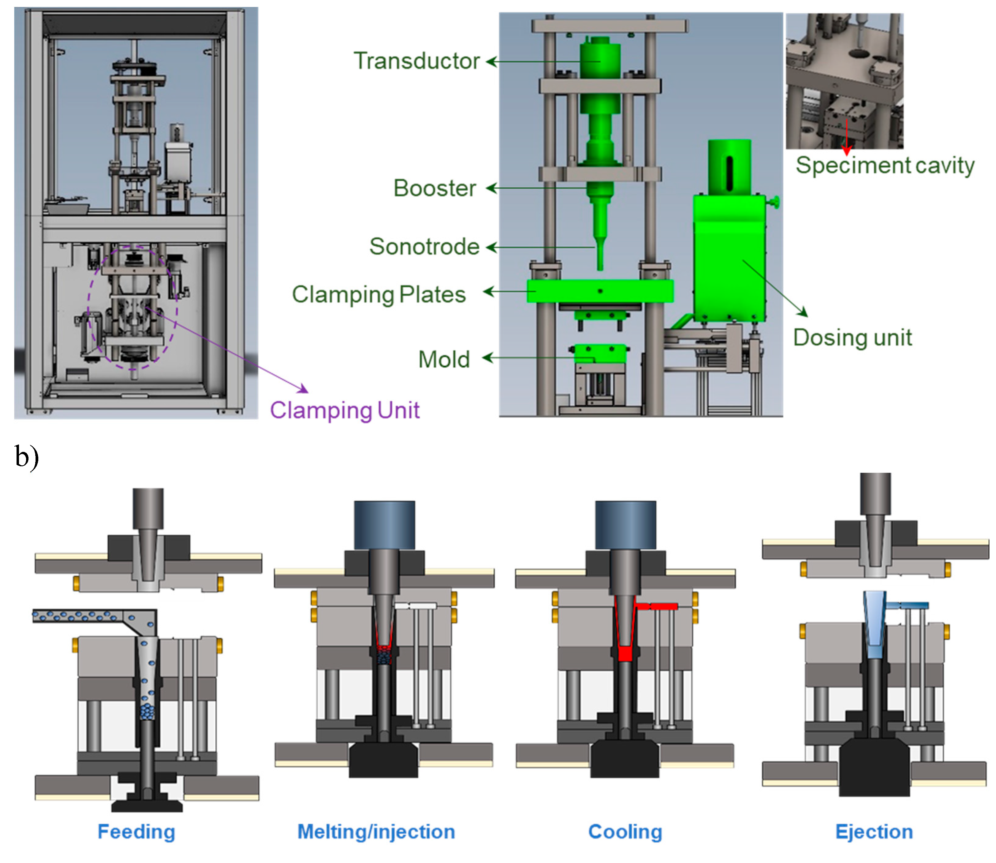
Figure 2.
GPC curves corresponding to the initial P3HB pellets (blue), P3HB sample processed under optimal conditions (i.e., amplitude of 36 %, plunger velocity of 2.5 mm/s) (orange), and sample processed under non optimal conditions (i.e., amplitude of 80 %, plunger velocity of 4 mm/s) (black).
Figure 2.
GPC curves corresponding to the initial P3HB pellets (blue), P3HB sample processed under optimal conditions (i.e., amplitude of 36 %, plunger velocity of 2.5 mm/s) (orange), and sample processed under non optimal conditions (i.e., amplitude of 80 %, plunger velocity of 4 mm/s) (black).
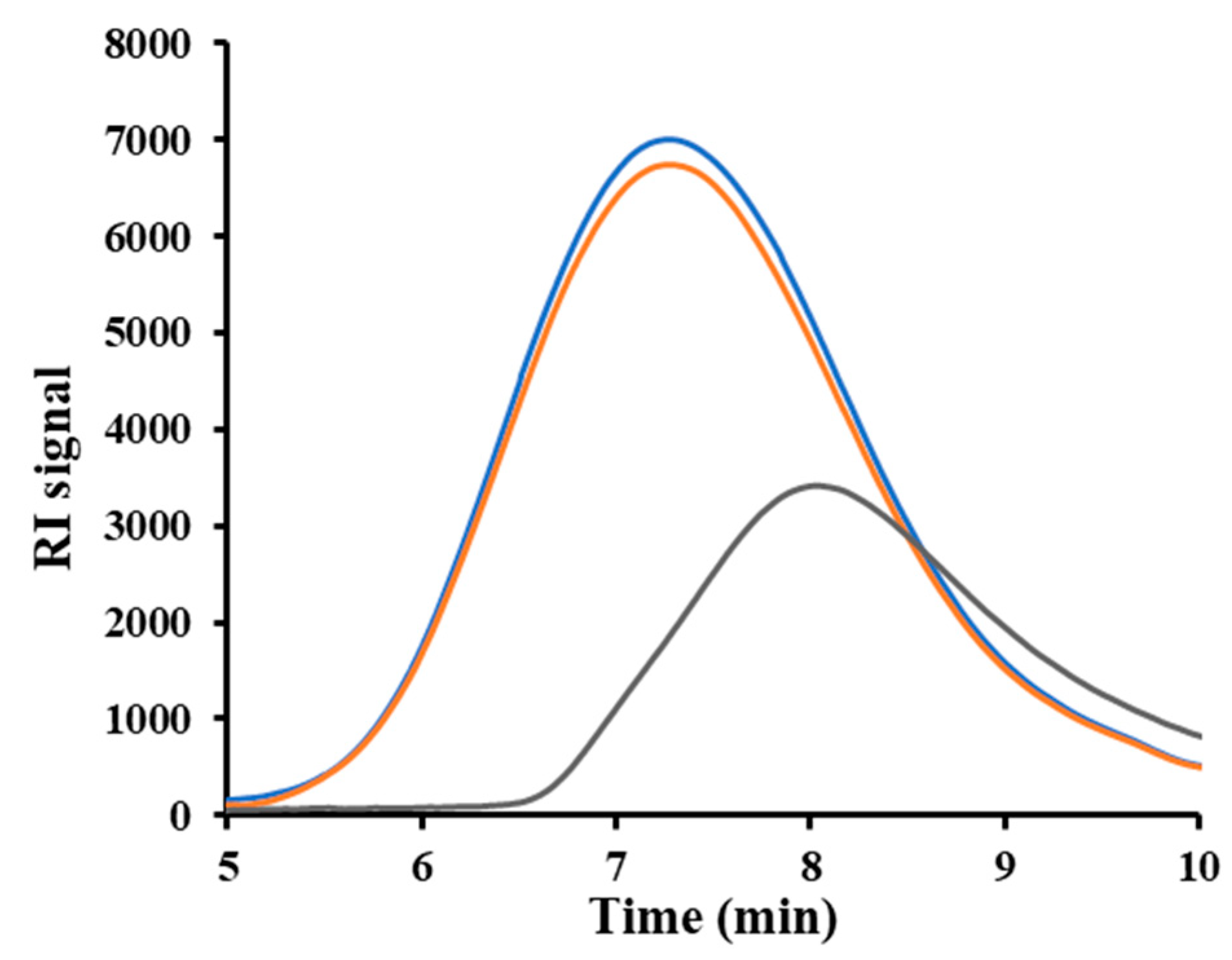
Figure 3.
FTIR spectra of raw P3HB (green line) and molded P3HB specimens obtained by the USM technology under optimal (red line), non-optimal conditions (black line) and by conventional microinjection (blue line). Black ellipsoids point out the appearance of a new carbonyl bands and intensity variation around 1200 cm-1.
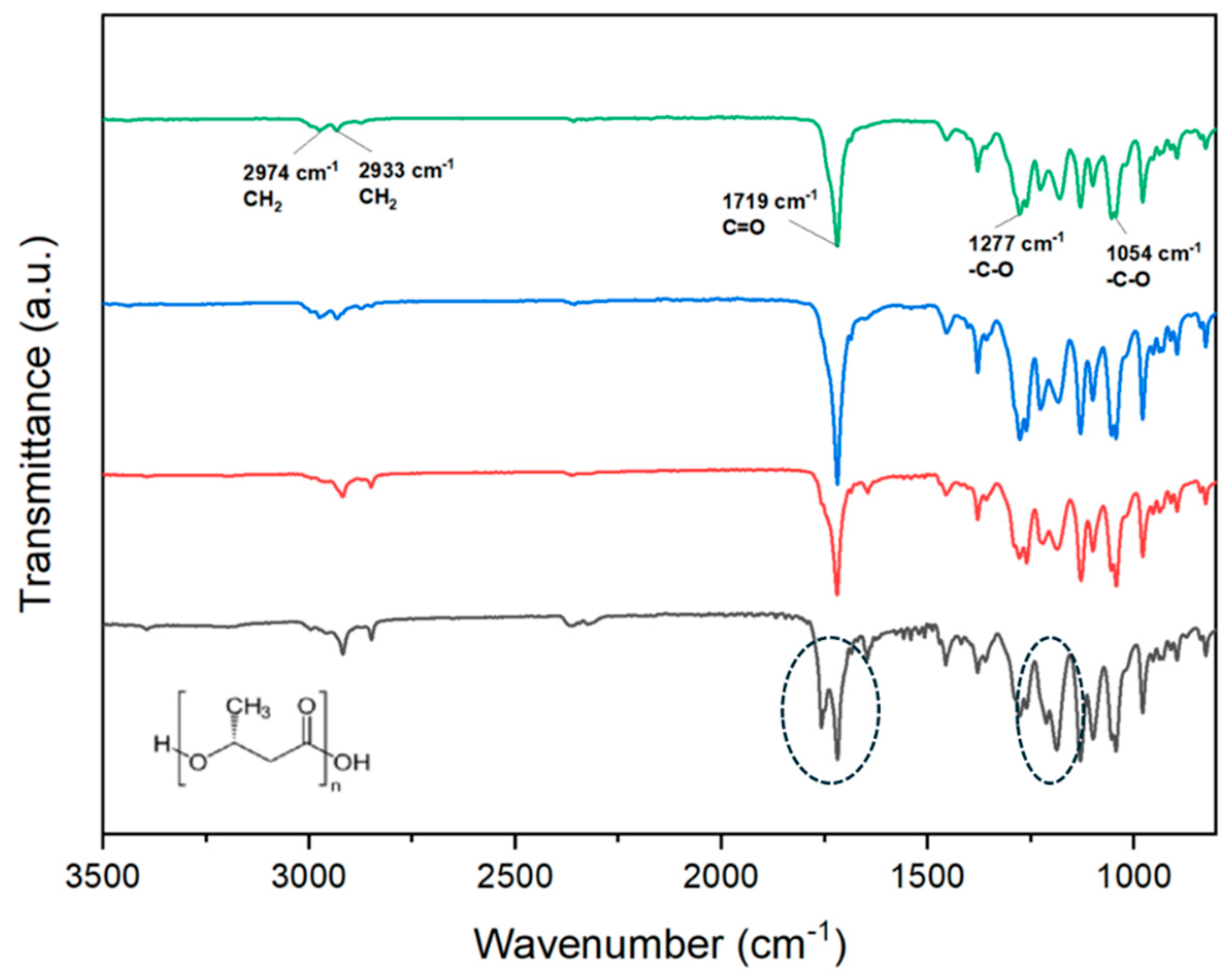
Figure 4.
(a) 1H NMR and (b) 13C NMR spectra and magnified peaks for raw P3HB (blue), conventional micromolded (red) and USM samples (black) processed under optimized conditions.
Figure 4.
(a) 1H NMR and (b) 13C NMR spectra and magnified peaks for raw P3HB (blue), conventional micromolded (red) and USM samples (black) processed under optimized conditions.
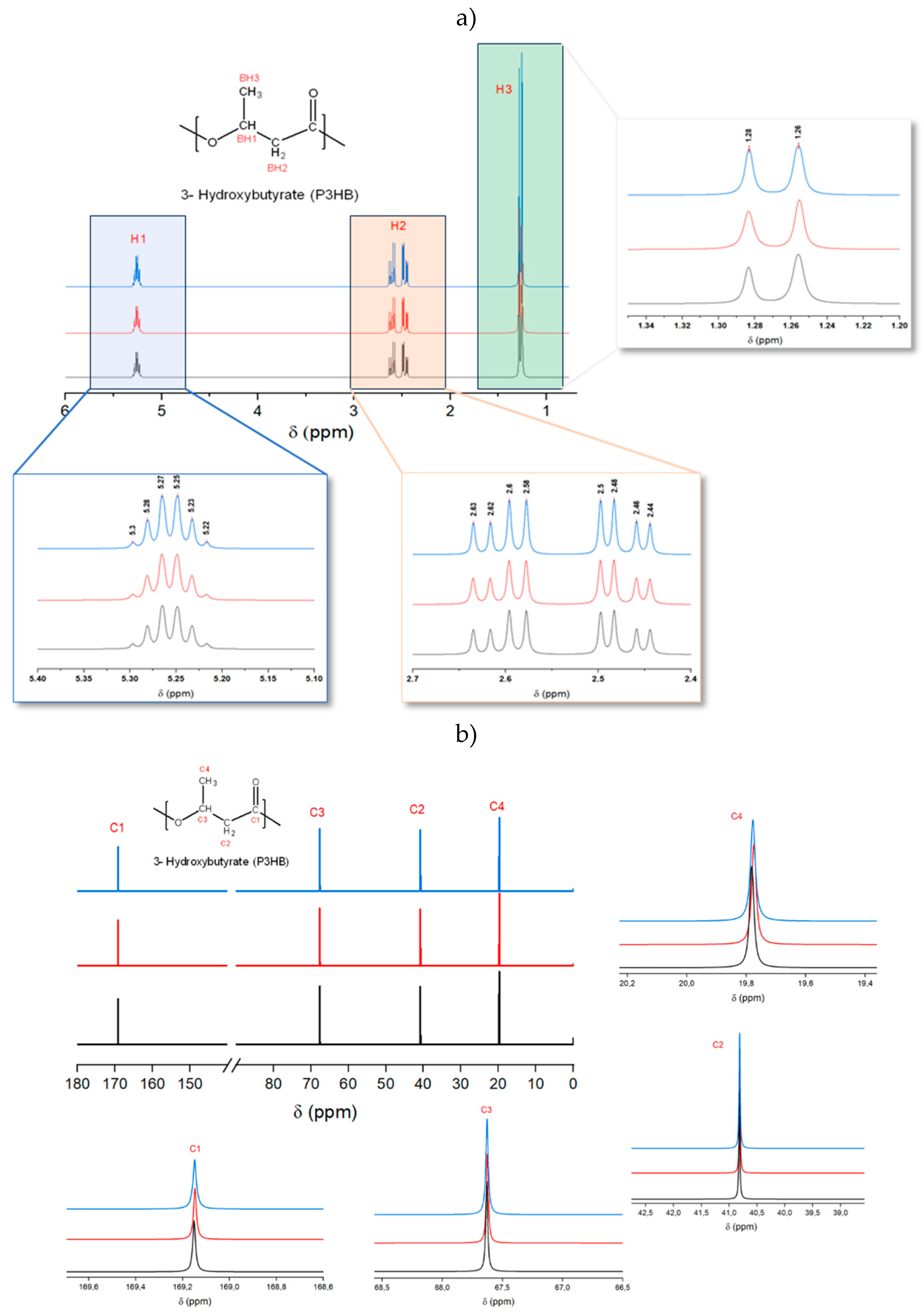
Figure 5.
SEM micrographs showing different low magnification images of microinjected (a) and USM P3HB specimens (b). Outer (top) and cross-section (bottom) images are provided; (c) SEM micrograph showing a cross-section of an USM micromolded P3HB specimen where spherulitic aggregates with radial lamellae can be envisaged (white dashed ellipsoid).
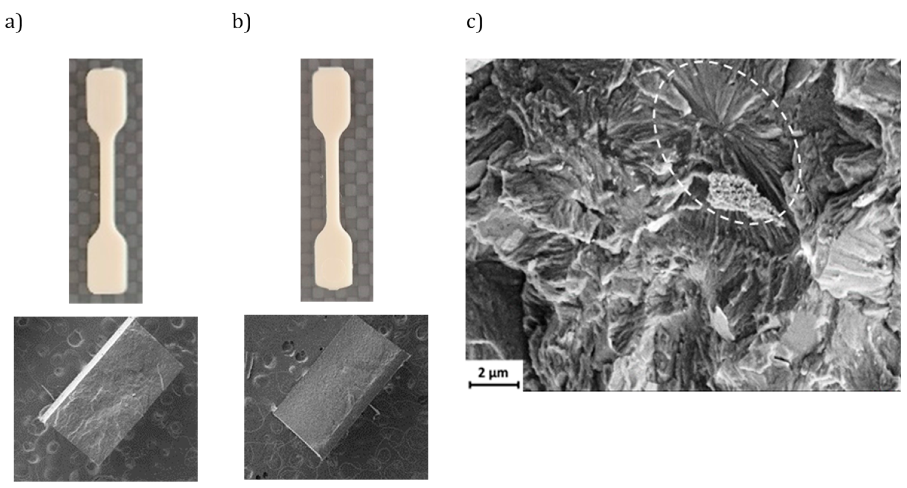
Figure 6.
(a) X-ray diffraction profile of a USM processed specimen of P3HB; (b) X-ray diffraction profiles showing the region between 13 and 18 nm-1, which is highly susceptible to the aging process. Melt extruded sample (blue), USM processed sample (black) and USM processed sample after an aging process (orange).
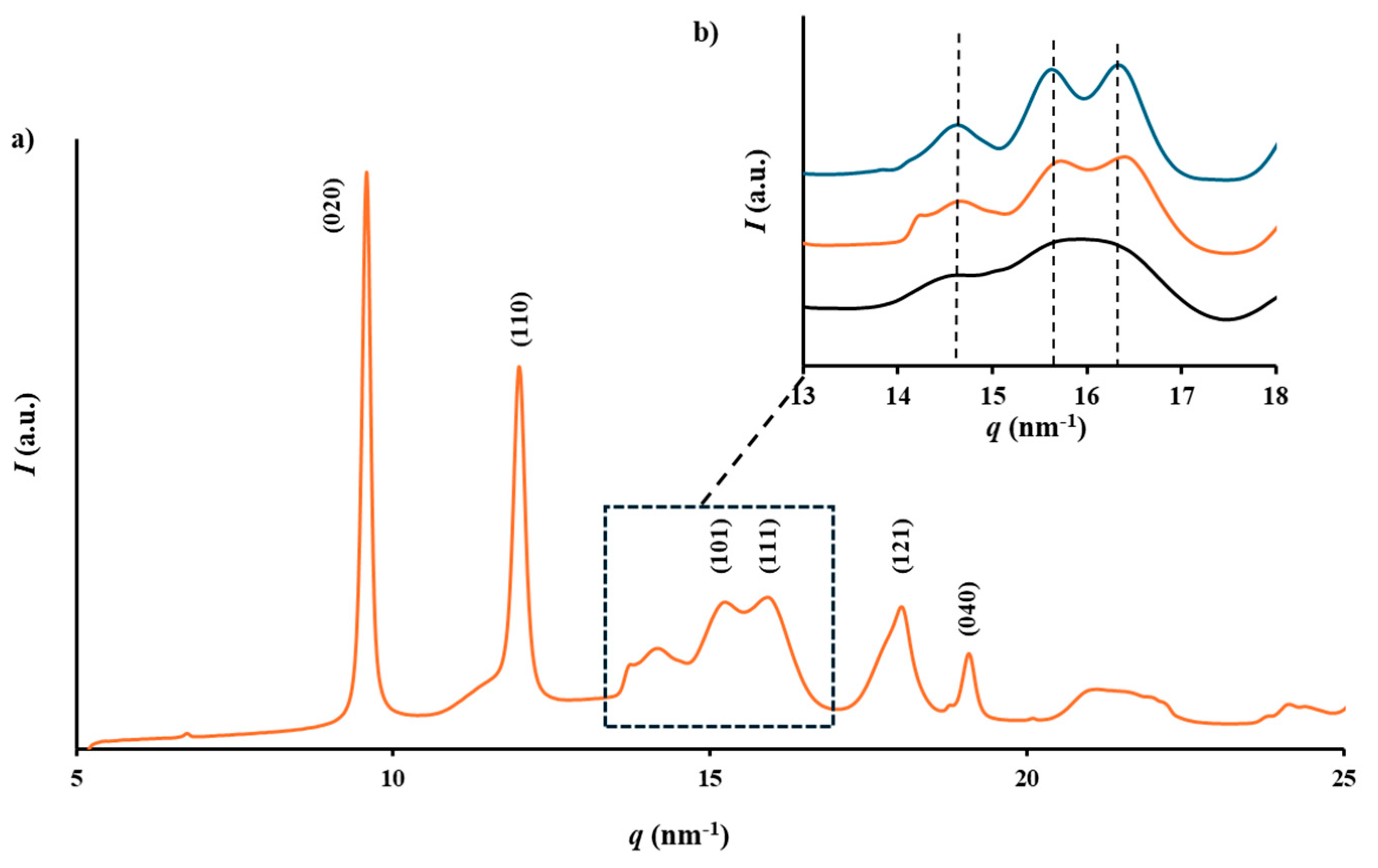
Figure 7.
(a) DSC first heating; (b) cooling; and (c) second heating runs for extruded P3HB specimens (red lines) and micromolded P3HB specimens obtained by conventional microinjection (blue lines) and by the USM technology (green lines).
Figure 7.
(a) DSC first heating; (b) cooling; and (c) second heating runs for extruded P3HB specimens (red lines) and micromolded P3HB specimens obtained by conventional microinjection (blue lines) and by the USM technology (green lines).
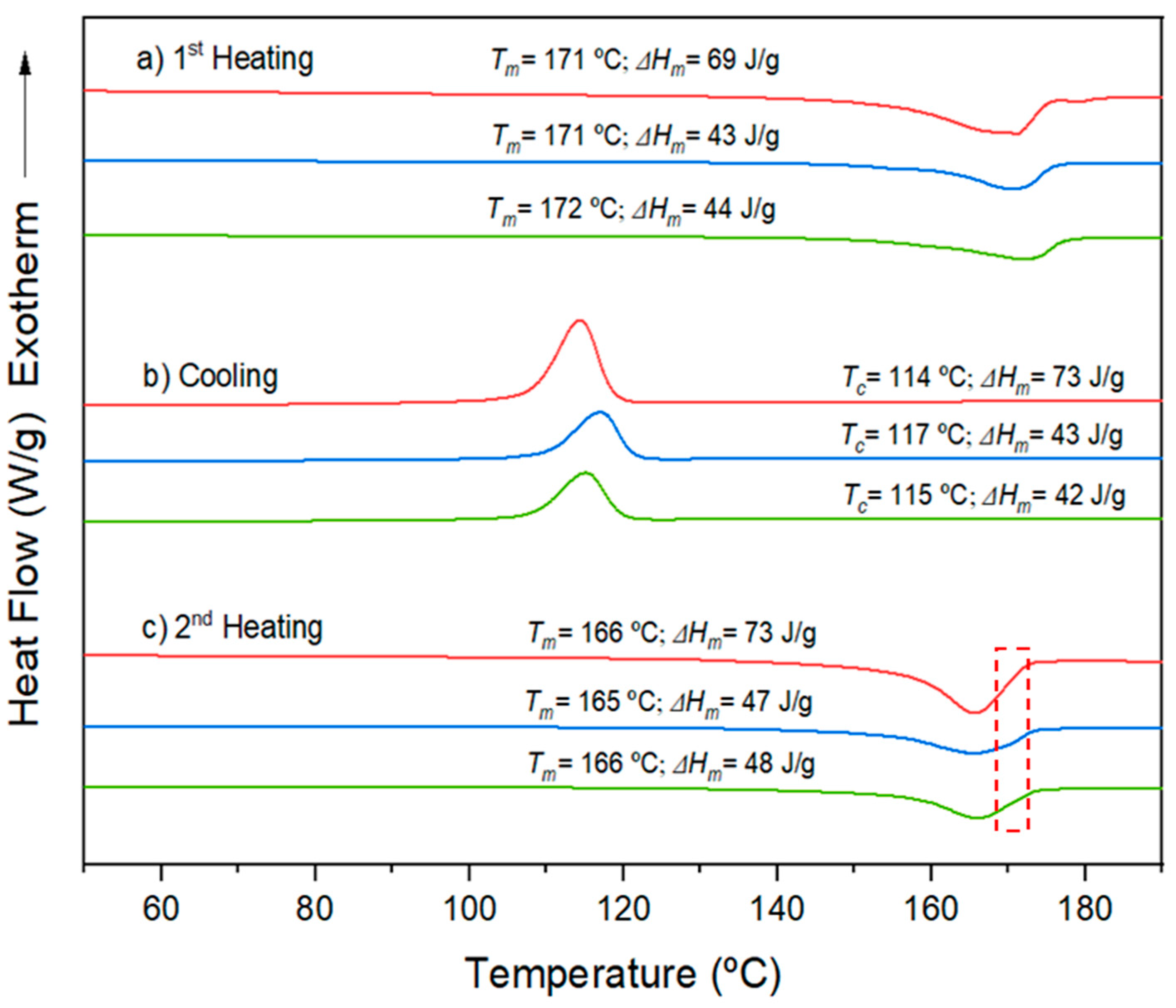
Figure 8.
(a) TEM micrographs at decreasing magnification from top to bottom of P3HB/C20 (left) and P3HB/C116 (right) nanocomposites with a clay content of 5 wt%; (b) SEM micrographs of P3HB/C20 (left) and P3HB/C116 (right) nanocomposite cross-sections. The clay content was 5 wt% and the samples were processed by USM technology. Dashed ellipsoids point out the presence of exfoliated clays.
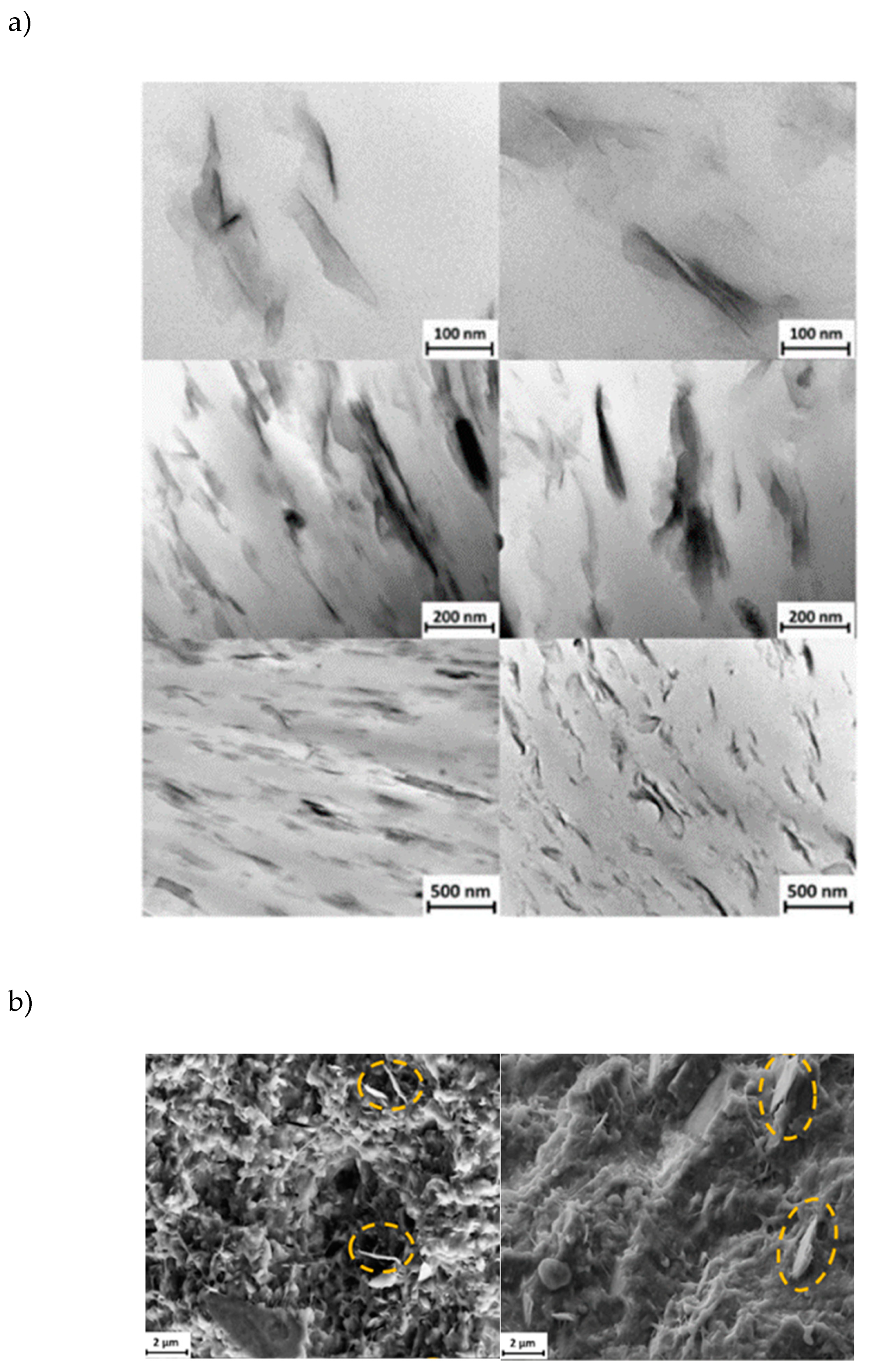
Figure 9.
X-ray diffraction profile of Cloisite C116, Cloisite C20 and USM processed specimen of P3HB with 8 wt% of C116 and C20. .
Figure 9.
X-ray diffraction profile of Cloisite C116, Cloisite C20 and USM processed specimen of P3HB with 8 wt% of C116 and C20. .
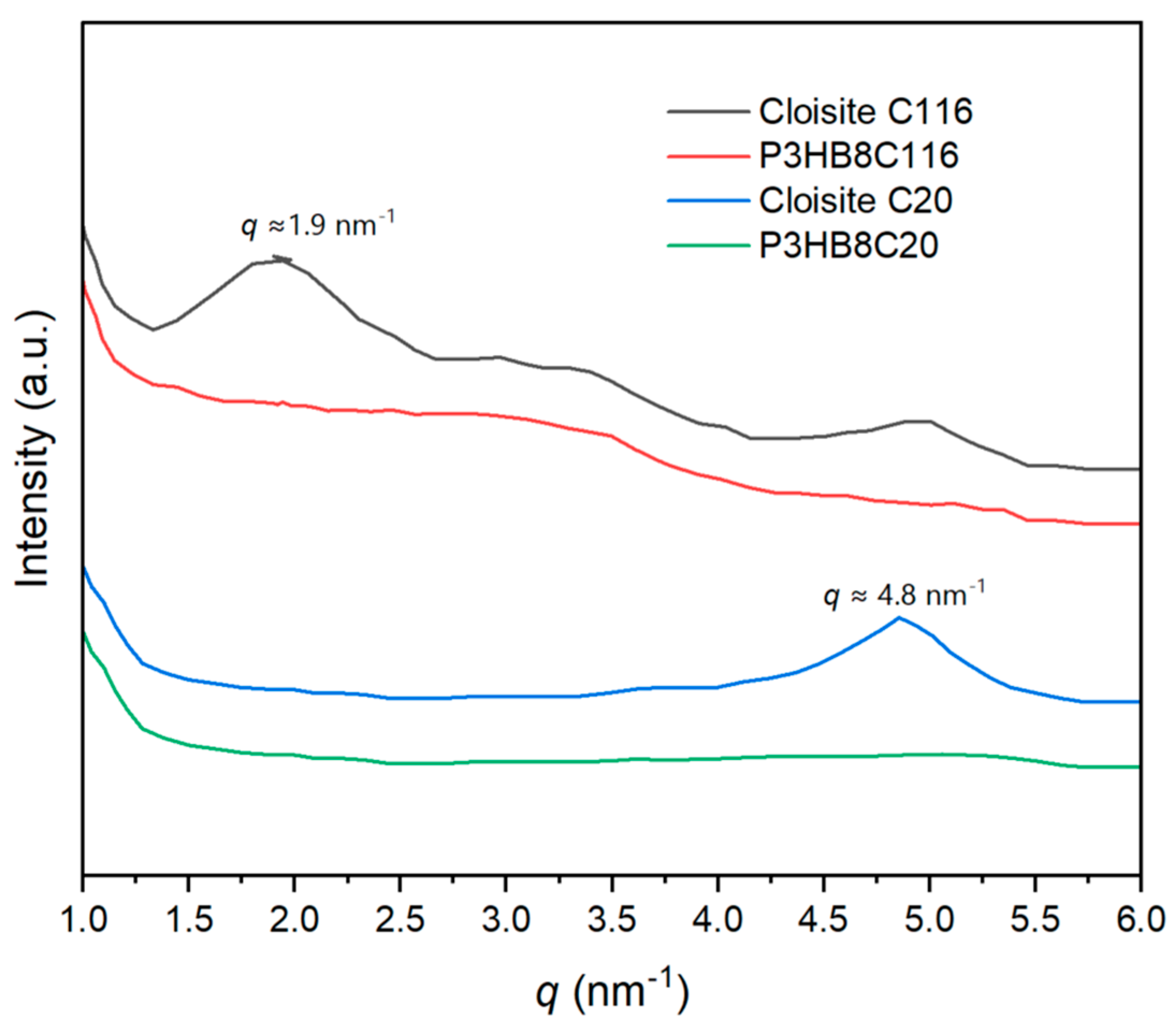
Figure 10.
(a) TGA and (b) DTGA curves of extruded P3HB (green) and different USM processed samples: distal (black) and proximal (pink) parts of nanocomposites with 5 wt% of Cloisite C116, proximal part of the nanocomposite with 5 wt% of Cloisite C20 (blue) and proximal part of the specimen with 8 wt% (lilac) of Cloisite C116.
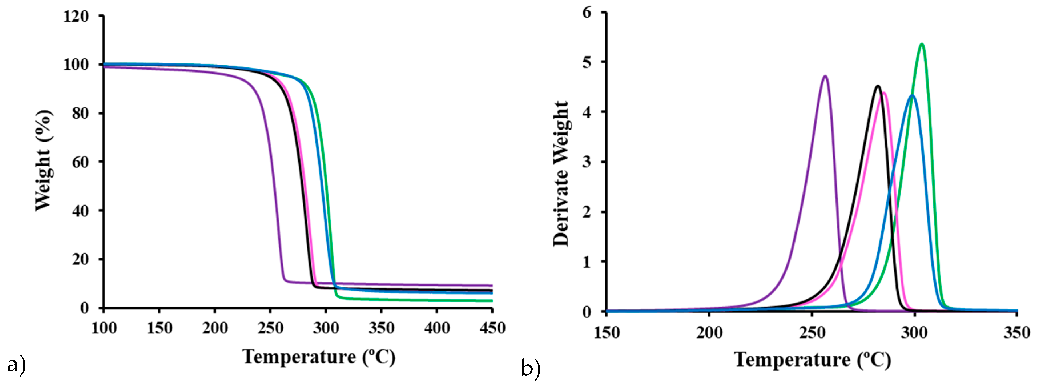
Figure 11.
DSC heating (a,b) and cooling (c,d) runs of micromolded P3HB/C20 (a,c) and P3HB/C116 (b,d) specimens obtained by the USM technology under the optimal conditions. Nanocomposites with 3, 5 and 8 wt% are represented by black, red and blue curves, respectively.
Figure 11.
DSC heating (a,b) and cooling (c,d) runs of micromolded P3HB/C20 (a,c) and P3HB/C116 (b,d) specimens obtained by the USM technology under the optimal conditions. Nanocomposites with 3, 5 and 8 wt% are represented by black, red and blue curves, respectively.
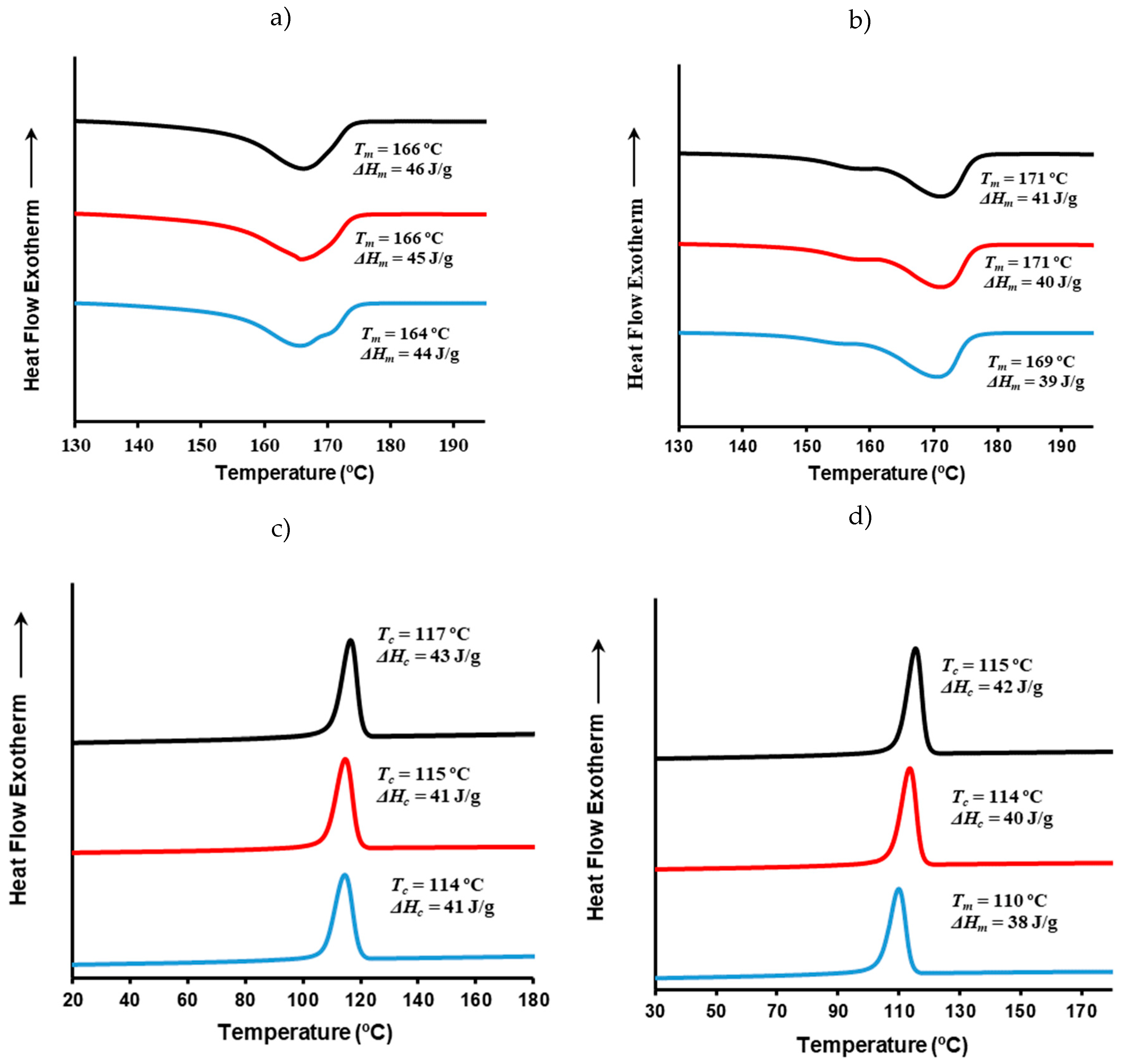
Figure 12.
(a) DSC heating curves of the melt crystallized P3HB/C20 nanocomposites at temperatures of 135 ºC, 132 ºC, 130 ºC, 128 ºC and 125 ºC from top to bottom; (b) Hoffman-Week plot for the P3HB and P3HB/C20 nanocomposite containing 5 wt% of clay.
Figure 12.
(a) DSC heating curves of the melt crystallized P3HB/C20 nanocomposites at temperatures of 135 ºC, 132 ºC, 130 ºC, 128 ºC and 125 ºC from top to bottom; (b) Hoffman-Week plot for the P3HB and P3HB/C20 nanocomposite containing 5 wt% of clay.
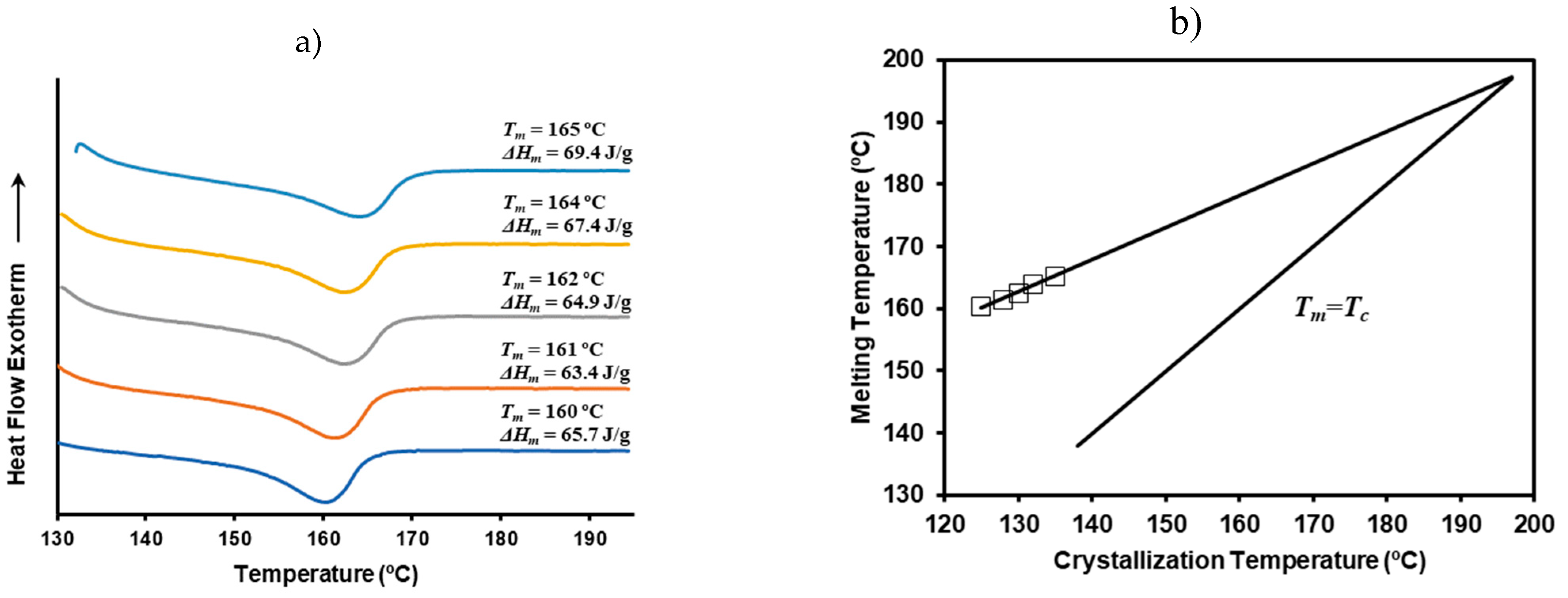
Figure 13.
(a) Stress-strain curves for neat P3HB specimens processed by USM with the nodal point configuration. Samples differ in the storage time: 1 day (blue), 1 month (red), 1 year (black); (b) Stress-strain curves for neat P3HB (blue), PHB5C20 (red) and PHB5C166 (black) specimens processed by USM.
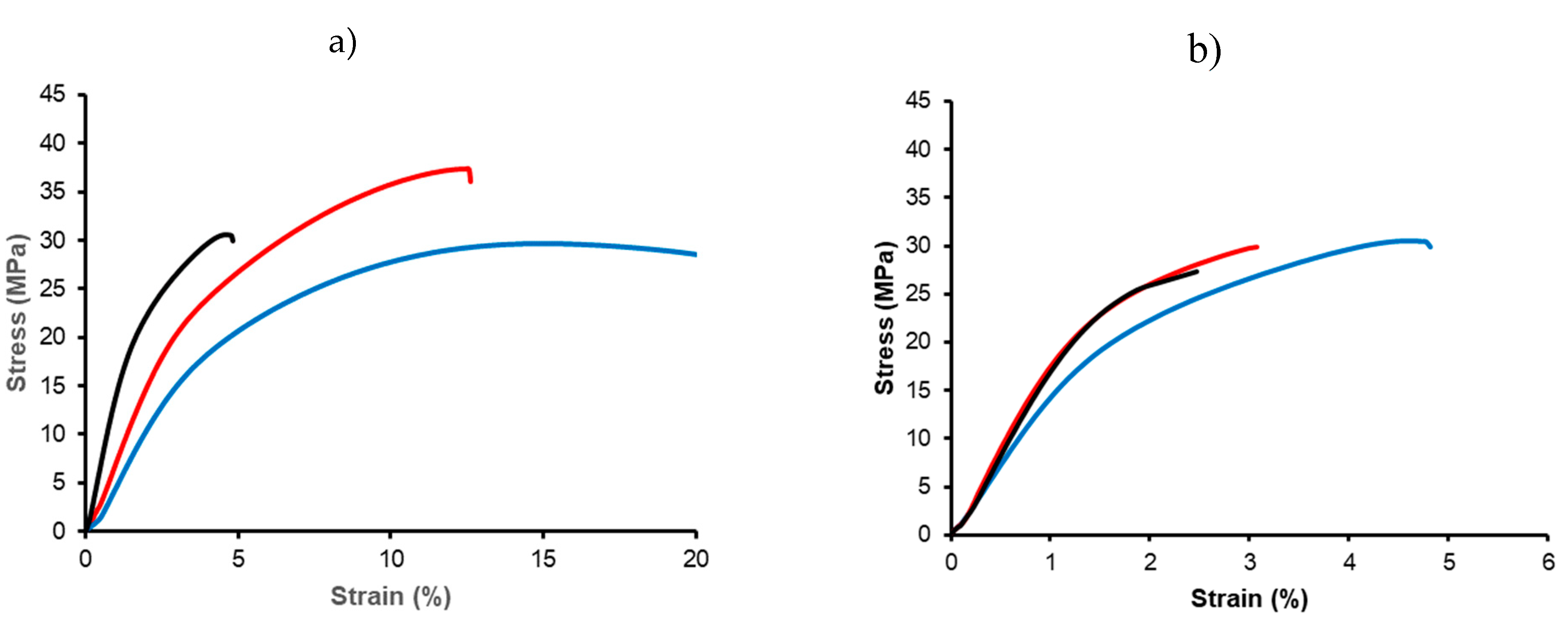

Table 1.
Processing windows (plunger velocity and amplitude) for P3HB (Test 1 - 4) and for P3HB with 5 % of Cloisite 20 (Test 5 - 8). Mechanical properties of processed specimens (tensile strength, TS; elongation at break, Eb), and mold temperature (T) and pressure (P) are indicated for each condition.
| Test | Amplitude | Plunger Vel. (mm/s) |
TS (MPa) |
Eb (%) |
T (ºC) |
P (bar) |
|---|---|---|---|---|---|---|
| 1 | 0.40 | 2.5 | 13.4±3.8 | 1.39±0.54 | 162.5±15.6 | 354±23.1 |
| 2 | 0.40 | 2.0 | 14.9±3.5 | 1.49±0.69 | 139.2±17.0 | 394±10.7 |
| 3 | 0.36 | 2.5 | 18.5±3.2 | 2.00±0.56 | 142.4±14.5 | 352±30.6 |
| 4 | 0.36 | 2.0 | 16.3±2.5 | 1.72±0.26 | 161.7±30.9 | 387±7.50 |
| 5 | 0.40 | 2.5 | 14.8±1.9 | 1.46±0.19 | 158.8±8.5 | 395±10.7 |
| 6 | 0.40 | 2.0 | 18.1±0.9 | 1.76±0.21 | 165.5±2.7 | 395±15.4 |
| 7 | 0.36 | 2.5 | 20.9±1.3 | 2.15±0.27 | 138.4±12.9 | 394±12.1 |
| 8 | 0.36 | 2.0 | 18.6±4.5 | 1.87±0.67 | 145.9±26.1 | 382±7.00 |
Table 2.
Average molecular weights for USM processed P3HB samples and the pristine pellet as a control for comparison. For completeness, data from a micro-injected P3HB sample are also included.
Table 2.
Average molecular weights for USM processed P3HB samples and the pristine pellet as a control for comparison. For completeness, data from a micro-injected P3HB sample are also included.
| Sample |
Mn (g/mol) |
Mw (g/mol) |
PI | Amplitude (%) |
Plunger velocity (mm/s) |
|---|---|---|---|---|---|
| P3HB (Pellet) | 58,700 | 135,400 | 2.3 | ||
| P3HB (USM) | 57,000 | 134,000 | 2.3 | 36 | 2.5 |
| P3HB (USM) | 43,308 | 90,768 | 2.1 | 40 | 4.0 |
| P3HB (USM) | 40,811 | 90,605 | 2.2 | 43 | 4.5 |
| P3HB (USM) | 33,739 | 71,031 | 2.1 | 45 | 5.0 |
| P3HB (Micro-injection) | 41,182 | 85,466 | 2.0 |
Table 3.
Average molecular weights and polydispersity index of representative USM processed samples of P3HB and the initial pellet as a control. For the sake of completeness data corresponding to microinjected pieces containing 5 wt% of C20 and C166 are also given.
Table 3.
Average molecular weights and polydispersity index of representative USM processed samples of P3HB and the initial pellet as a control. For the sake of completeness data corresponding to microinjected pieces containing 5 wt% of C20 and C166 are also given.
| Sample | Mw | Mn | PI |
|---|---|---|---|
| P3HB (Pellet) | 135,400 | 58,700 | 2.3 |
| P3HB (USM) | 134,000 | 57,000 | 2.3 |
| P3HB3C20 | 128,000 | 55,600 | 2.3 |
| P3HB5C20 | 126,800 | 54,900 | 2.3 |
| P3HB5C20a | 110,800 | 51,182 | 2.1 |
| P3HB8C20 | 119,800 | 50,200 | 2.4 |
| P3HB3C116 | 103,300 | 45,900 | 2.3 |
| P3HB5C116 | 96,100 | 42,900 | 2.2 |
| P3HB5C116a | - | - | - |
| P3HB8C116 | 87,000 | 41,000 | 2.1 |
aConventional microinjected sample.
Table 4.
Young modulus (E), maximum strength (TSmax), and break elongation (Eb) for processed specimens of P3HB and correspondent nanocomposites with C20 and C166 clays.
Table 4.
Young modulus (E), maximum strength (TSmax), and break elongation (Eb) for processed specimens of P3HB and correspondent nanocomposites with C20 and C166 clays.
| Sample | E (MPa) | TSmax (MPa) | Eb (%) |
|---|---|---|---|
| P3HBa | 1,560 ± 76 | 31.7 ± 1.2 | 5.0 ± 0.2 |
| P3HBb | 1,390 ± 45 | 25.9 ± 4.1 | 6.0 ± 0.3 |
| PHB3C20a | 1,850 ± 42 | 27.9 ± 3.5 | 3.1 ± 0.1 |
| PHB5C20a | 1,990 ± 51 | 29.2 ± 2.3 | 3.2 ± 0.2 |
| PHB8C20a | 2,140 ± 55 | 29.2 ± 3.2 | 2.7 ± 0.1 |
| PHB3C20b | 1,480 ± 62 | 26.2 ± 2.6 | 2.6 ± 0.2 |
| PHB5C20b | 1,270 ± 42 | 24.9 ± 2.8 | 2.4 ± 0.3 |
| PHB8C20b | 1,570 ± 54 | 25.2 ± 3.0 | 1.8 ± 0.2 |
| PHB3C116a | 1,840 ± 52 | 27.5 ± 3.4 | 2.5 ± 0.2 |
| PHB5C116a | 2,010 ± 84 | 26.2 ± 4.1 | 2.3 ± 0.3 |
| PHB8C116a | 2,190 ± 68 | 20.6 ± 2.6 | 1.3 ± 0.2 |
aUSM. bConventional microinjection.
Disclaimer/Publisher’s Note: The statements, opinions and data contained in all publications are solely those of the individual author(s) and contributor(s) and not of MDPI and/or the editor(s). MDPI and/or the editor(s) disclaim responsibility for any injury to people or property resulting from any ideas, methods, instructions or products referred to in the content. |
© 2024 by the author. Licensee MDPI, Basel, Switzerland. This article is an open access article distributed under the terms and conditions of the Creative Commons Attribution (CC BY) license (https://creativecommons.org/licenses/by/4.0/).
Copyright: This open access article is published under a Creative Commons CC BY 4.0 license, which permit the free download, distribution, and reuse, provided that the author and preprint are cited in any reuse.


