
Submitted:
03 September 2025
Posted:
04 September 2025
You are already at the latest version
Abstract
The demand for organ transplantation continues to rise worldwide, intensifying the gap between supply and demand and driving research in tissue engineering (TE). Bioprinting, particularly light-based vat photopolymerization (VP) methods such as digital light processing (DLP), has emerged as a promising strategy to fabricate complex, cell-compatible tissue constructs with high precision. In this study, we developed an open-source, bottom-up DLP bioprinter designed to provide a cost-effective and modular alternative to commercial systems. The device was built from commercially available components and custom-fabricated parts, with tolerance allocation and deviation analyses applied to ensure structural reliability. Mechanical and optical subsystems were modeled and validated, and the control architecture was implemented on the Arduino platform with a custom Python-based graphical interface. The system achieved a theoretical Z-axis resolution of 5 um and a vertical travel range of 50 mm, with accuracy and repeatability comparable to research-grade bioprinters. Initial printing trials using polyethylene glycol diacrylate (PEGDA) hydrogels demonstrated high-fidelity microfluidic constructs with adequate dimensional precision. Collectively, these results validate the functionality of the proposed system and highlight its potential as a flexible, precise, and cost-effective platform that is also easy to customize to advance the democratization of biofabrication in TE.
Keywords:
direct light processing
; bioprinting
; tissue engineering
; tolerance allocation
; vat photopolymerization
; open source
1. Introduction
Worldwide, the number of patients in need of organ transplantation continues to grow, driven by longer life expectancy and expanding population size [1]. Research findings suggest that donor shortages have resulted in an ongoing disequilibrium between organ supply and demand [2]. Consequently, tissue engineering (TE) is emerging as a rapidly growing discipline dedicated to repairing, replacing, or regenerating tissues and organs through the convergence of cell biology, materials science, and biomedical engineering [3]. In recent years, a new approach has rapidly advanced, shifting from a relatively niche technology to a central component of TE, three-dimensional (3D) bioprinting. Bioprinting is a manufacturing process that utilizes bioinks, formulated from living cells and/or biodegradable biomaterials, often in combination with bioactive components, to create engineered constructs with biological functionality [4]. The transition towards a main component in TE reflects the growing recognition of its potential to fabricate 3D constructs using biocompatible materials that ultimately become functional tissues, offering potential solutions for the replacement of damaged or diseased organs [5,6,7,8]. Beyond this, bioprinting also plays an essential role in the development of engineered in vitro biomimetic constructs that mimic human physiological responses. These constructs serve as advanced platforms for drug testing, addressing the limitations of traditional in vitro models and reducing the need for animal experimentation [9].
The main advances in 3D bioprinting have occurred through the development of novel bioinks and the modification of conventional 3D printers [5,7]. Nowadays, there are four primary bioprinting technologies: extrusion-based, jetting-based, laser-assisted, and light-based vat photopolymerization (VP) bioprinting [6,10,11]. Extrusion-based bioprinting has probably emerged as the most commonly employed technique, largely due to its affordability and its capability to process and print a wide range of cells and biomaterials simultaneously [12]. Jetting-based bioprinting operates on the same working principle as conventional inkjet printers, wherein droplets of bioink are selectively deposited to form successive layers on a hydrogel substrate or Petri dish. Laser-assisted bioprinting employs a focused laser beam to deposit biomaterials with cells onto a target surface, but typically results a low cell viability, due to the heat generated by the laser [13]. Light-based VP bioprinting involves the use of photosensitive materials that undergo curing and solidification upon exposure to light [14]. The technology is one of the most precise of the bioprinting techniques. Early implementations of light-based VP bioprinting [15] were limited by a lack of suitable photosensitive hydrogels and the cytotoxic effects of the ultraviolet (UV) light employed. Recent advancements in the field have addressed these initial issues through research on new visible-light-sensitive materials, which significantly enhance biocompatibility and facilitate the use of this technique in TE [10].
Light-based VP bioprinting encompasses all methods that employ photosensitive materials and rely on light-induced polymerization of bioinks [11,16]. These techniques are generally classified into single-photon and multi-photon polymerization [16]. Single-photon polymerization primarily includes stereolithography apparatus (SLA), digital light processing (DLP), and volumetric printing [17]. Among the various VP-based techniques, DLP has probably emerged as one of the most promising methods for biofabrication [13,14]. DLP bioprinting employs projected digital photomasks to induce localized photopolymerization of a liquid bioink, thereby assembling constructs in a layer-by-layer fashion. This technique uses a digital micromirror device (DMD) as a light modulator, enabling precise digital control of high-resolution, pixel-based light patterns that preserve structural fidelity [11]. The integration of the DMD considerably accelerates the bioprinting process [18]. Compared to SLA, DLP significantly accelerates the printing process by curing entire layers simultaneously rather than tracing each feature point-by-point with a laser. Unlike volumetric bioprinting, DLP can produce constructs of larger volume while maintaining a spatial resolution that remains comparable to that of volumetric techniques [10]. Therefore, the key advantages of this approach include rapid printing speed, sufficient resolution for biofabrication applications, and comparatively low manufacturing cost.
DLP has attracted increasing interest in both commercial [19] and academic environments. Commercial systems such as the Lumen X platform by Cellink (Gothenburg, Sweden) exemplify the growing adoption of DLP in biomedical research. Simultaneously, various research teams have proposed custom-built DLP bioprinters to expand functionality and reduce fabrication costs by embracing the do-it-yourself (DIY) philosophy [11]. Owing to these benefits, research groups worldwide have proposed novel developments and design modifications, mostly aimed at broadening the applicability and performance of this technique within their laboratories. Several recent studies have worked on expanding the versatility and growing sophistication of DLP-based bioprinting systems. For example, Grigoryan et al. (2019) developed a DLP system capable of fabricating complex, vascularized tissue constructs, including functional alveolar lung units that exhibited effective blood oxygenation [15]. Building upon this foundation, the same research group later introduced a multi-material DLP platform incorporating a layer-cleaning mechanism, thereby enabling the fabrication of intricate, multi-material tissue architectures [20]. In parallel, Bhusal et al. (2022) presented a distinct multi-material DLP bioprinter that employed a rotary base system for material switching, further advancing the modularity of bioprinting hardware [21]. Complementing these hardware innovations, Yang et al. (2024) addressed a key challenge in the field—thermal sensitivity of biological materials—by developing a low-temperature DLP printing process using collagen methacryloyl (ColMA) hydrogels. Their approach yielded mechanically stable constructs with high cell viability, highlighting the clinical potential of DLP platforms for patient-specific scaffold fabrication [22]. Further analyses of different VP bioprinting technologies, available photocurable materials, and future developments in the area of these technologies can be found in several comprehensive reviews of existing literature [11,16,17,23,24,25]. Collectively, these advances underscore the rapid evolution of DLP bioprinting into a versatile and clinically promising platform, with the potential to transform the field of TE.
There is a need to develop flexible DLP bioprinters under open-source licenses and DIY designs. DIY bioprinters are typically developed for targeted applications, and their design is strongly influenced by the characteristics of the bioinks utilized [11]. This work presents the development of an open-source bottom-up DLP bioprinter designed to offer a cost-effective alternative to commercial systems. The bioprinter is easy to personalize and customize to best fit researchers’ needs. The DLP projector can be easily exchanged with other systems. The system achieved superior z-axis resolution and precision relative to other research-grade bioprinters after carrying out a thorough assessment of design tolerances often overlooked in other studies. Moreover, it operates entirely with open-source and free software, eliminating the need for proprietary applications. Initial print trials using polyethylene glycol diacrylate (PEGDA) hydrogels—without cells—demonstrated the system’s functionality. Taken together, these features established a robust, accessible, and highly precise DLP bioprinter that advances the democratization of biofabrication.
2. Materials and Methods
2.1. Materials
2.1.1. Mechanical Components
Custom-designed parts were manufactured using aluminum, steel, polylactic acid (PLA), and photo-polymer resin. Steel S275JR EN 10025-2 in sheet and 6061 aluminium blocks (Randrade S.L., Pontevedra, Spain) were machined to produce the required parts. PLA filament ( 1 spool, ) (Eolas Prints, S.L, Reocin, Spain) and Tough 2000 standard photopolymer resin from Formlabs (Formlabs Inc., Somerville, MA, USA) were used for the production of the small printed parts by both 3D printing technologies.
All the mechanical elements were commercially available. The vertical motion of the stage was solved using a KR1501A-0075-P0-00A0 (THK Co., Yokohama, Japan) linear guide providing a positioning repeatability and accuracy of and , respectively. Motion from the stepper motor was transmitted via a D16L23 flexible coupling (Zhejiang Longwei Tech Co., China) with 3 mm and 5 mm bores for the leadscrew and motor shafts. The structural frame was constructed using 30x 30 extruded aluminum profiles, coupled with 8 mm T-slot hammer head nuts (Bosch Rexroth, Lohr am Main, Germany). The structure was assembled using A2 stainless steel fasteners (Rational World S.L., Zaragoza, Spain) according to ISO 4762.
2.1.2. Electronic and Optical Systems
The electronic system was powered by a 24 VDC, 15 A power supply (Mouser Electronics, Inc., Barcelona, Spain), operating within an input voltage range of 110–220 VAC. A NEMA 11 closed-loop bipolar stepper motor model ESS11-01 (StepperOnline, Nanjing, China) was employed to drive the vertical axis. The control architecture was based on the Arduino platform. Specifically, an Arduino Mega 2560 microcontroller board (Arduino, Turin, Italy) served as the central processing unit (CPU) and was interfaced with a RAMPS 1.4 shield (RepRap Project, Bath, United Kingdom). An auxiliary Arduino Nano board was integrated to synchronize motion system components.
The optical system consisted of a LuxBeam 4KAc digital light projector equipped with a standard LRS-20 UV lens - nominal working distance of 90 , and LRS-WQm 1.0× lens with . (Visitech, Drammen, Norway). The LRS-20 UV configuration provided a pixel size of across an image area of 41.5 × , with a light-emitting diode (LED) array at a wavelength of 405 and with an output power of .
2.2. Mechanical Design
The bioprinter was designed with a bottom-up configuration, in which the DLP projector was positioned beneath the stage [26]. Mechanical modeling followed a bottom-up methodology, with each component designed a priori and independently. A modular architecture was employed to limit interdependence between its modules [27]. All components were modeled using Autodesk® Inventor (v2024, Autodesk, San Francisco, CA, USA).
The theoretical positioning resolution along the Z-axis, , was determined as:
where P is the lead of the screw in mm/rev, and N is the number of full steps per revolution of the stepper motor measured in steps/rev.
2.3. Tolerance Allocation and Deviation Analysis
Geometrical and dimensional tolerances were assigned according to the functional relevance of each component [28]. Structural elements, such as the bottom base or FDM-printed electronic supports, were limited by the manufacturing precision of their respective processes. By contrast, elements directly influencing optical accuracy and mechanical alignment—including the projector assembly, vat, and Z-axis platform—were subject to stricter dimensional and geometrical tolerances.
The analysis was performed under worst-case conditions to guarantee robust assembly and reliable performance. A top-to-bottom approach was applied for the base-projector assembly, including: (i) assessment of base parallelism deviations, (ii) evaluation of dimensional and perpendicularity tolerances of the spacers, and (iii) estimation of angular deviations in the projector supporting frames. The tolerances were distributed under the assumption that the upper surface of the base was perfectly horizontal, owing to the three-foot calibration system and the use of a circular bubble level. For the Z-axis system, potential inclinations around the X- and Y-axes were evaluated and converted into linear displacement errors over the full actuator stroke, to verify that these remained negligible compared with the theoretical repeatability of the motion mechanism.
Tolerance stack-up was analyzed through trigonometric relations, propagating local deviations into global angular errors. Deviation angle due to parallelism and perpendicularity errors was calculated as:
where is the parallelism or perpendicularity tolerance and is the horizontal distance considered.
For the spacer, the worst-case scenario occurred when two adjacent spacers reached the minimum and maximum limits of the dimensional tolerance, while the perpendicularity deviation attained its maximum value on opposite faces. The minimum admissible length was calculated as:
where d is the nominal length of the spacer, is the dimensional tolerance, and is obtained from Equation (2) for the perpendicularity tolerance. Conversely, the maximum length was calculated as:
where D is the spacer diameter. The angular deviation due to spacer tolerances, , was expressed as:
with denoting the distance between spacers.
The total angular deviation was obtained as the sum of all contributions. The regulation capacity r required for the adjustment screws was modeled as:
where is the distance between one screw and the line joining the other two.
Residual misalignment was estimated by comparing the maximum error with the design regulation range, and its effect on optical performance was quantified through the image translation at the focal plane, , and the pixel deformation, :
where is the distance between the projector reference surface and the focal plane, is the uncompensated angular deviation, and p is the original pixel dimension.
Finally, for the Z-axis linear guide, potential inclinations were converted into linear displacements errors using:
where s is the stroke of the linear guide, and and are the total angular deviations about the X- and Y-axes, respectively, obtained from Equation (2) for each geometrical tolerance and accumulated.
2.4. Fabrication Techniques
The fabrication techniques employed for prototype construction were high-speed machining for aluminum components and 3D printing for polymeric parts. Plasma cutting and turning were also used for the production of specific parts. Aluminum elements were produced using a Datron NEO 2 machining center (DATRON AG, Ober-Ramstadt, Germany). Steel sheets were cut using an CNC plasma router model 20.10 Hellraiser (Agri-cutter, Salamanca, Spain). Two technologies were employed for 3D printing: fused deposition modelling (FDM), using a Prusa i3 MK3S+ (Prusa Research®, Prague, Czech Republic), and stereolithography (SLA), using a Form 3 printer (Formlabs, Somerville, MA, USA). All machines were provided by the Escuela Técnica Superior de Ingeniería Industrial de Béjar, Universidad de Salamanca, Spain.
2.5. Dimensional and Geometrical Verification Protocols
Dimensional and geometrical verifications were conducted using calibrated metrology instruments. Measurements of linear dimensions, hole diameters, and geometrical tolerances—such as parallelism and perpendicularity—were performed.
Dimensional verification was carried out using Vernier calipers and micrometers (Insize Ltd., Jiangsu, China), depending on the required precision and measurement range. Hole diameters were measured using internal micrometers and bore gauges, where applicable (Mitutoyo Corporation, Tokyo, Japan). For the assessment of geometrical tolerances—flatness, perpendicularity, and parallelism—a granite surface plate was used as the reference plane, along with dial indicators (Insize Ltd., Jiangsu, China) mounted on appropriate stands to detect deviations.
All instruments were verified for calibration validity prior to use and operated under controlled environmental conditions to minimize measurement uncertainty. Multiple measurements were taken for each dimension, and the arithmetic mean was calculated. The standard deviation was maintained below one-tenth of the specified dimensional tolerance. A similar protocol was followed for geometrical verification: three repeated measurements were performed, and the mean and standard deviation were computed. Here as well, the standard deviation was required to be equal to or less than one-tenth of the corresponding geometrical tolerance, ensuring consistency and repeatability in the verification process.
2.6. System Control and Programming
A modified version of an already published Marlin 3D printer firmware [15] was used as the basic on the ATmega2560 microcontroller. The firmware is deposited into the open data repository for this work. An Arduino Nano served as an intermediary communication interface between the computer and the motor. Communication with the computer was established via a serial port for the bioprinter and through a Video Graphics Array (VGA) connection for the projector. The system integrates a stepper motor with an internal driver, a Z-axis limit switch, and a 24 V fan for cooling the motor driver. The stepper motor is controlled by the ATmega2560 through the RAMPS 1.4 shield, while the Arduino Nano monitors the state of the motor’s ENABLE pin to determine whether the motor is active. Based on this status, the computer software projects the corresponding layer image. The electronic schematic and wiring diagram of the system are presented in Figure 1.
Fabrication and manual control of the bioprinter was managed with new graphical user interface (GUI) application. The GUI was developed in Python (version 3.12) with the core functionality relying only packages like Pygame [29] and CustomTkinter [30]. The GUI controls the systems by sending GCode commands for the vertical movement of the stage, and a sequence of photomasks (images) to the projector, which represent the digital model. The STL (Standard Tessellation Language) files of the bioprinting models were prepared for 3D printing using the freely available Chitubox software (Chitubox, Guangdong, China), generating a projection image or photomask for each layer.
2.7. Mechanical Assembly and System Calibration
The bioprinter assembly began with construction of the structural frame to ensure stable connections and precise component fitting. The linear guide was then calibrated relative to the frame, maintaining perpendicularity to the upper base and parallelism to the structure. Fine adjustments were achieved by loosening the guide screws before final tightening.
The projection module was installed after alignment of the frame and the linear guide. The upper base was leveled using a bubble level and the calibration system. The projector was subsequently aligned using its three adjustable screws and the bubble level, and its focusing mechanism was adjusted symmetrically to maintain horizontality. Once sharpness was optimized, the fixing screws were tightened to prevent shifts due to vibrations.
Stage aligment was performed to ensure homogeneous layer thickness. The build platform was manually lowered through the GUI until it nearly touched the resin bucket. The ball-joint screws were loosened, and the vertical adjustment was used to bring the platform into contact with the Polydimethylsiloxane (PDMS)-coated bottom surface. The screws were then re-tightened and the adjustment nut was fixed. The Z-axis stroke was calibrated by running the homing function in the GUI, defining the reference position of the stage.
2.8. Analysis of Accuracy and Repeatability
The accuracy and repeatability of the machine were evaluated using an adaptation of the ISO 9283:1998 standard, which is intended for characterizing these parameters in numerically controlled axes [31]. The machine was tested at the same location where it had previously been calibrated. The test was conducted while maintaining the room temperature within the range of 18– 22 °C.
The positive direction of the linear guide was defined as upward. The load applied during testing corresponded to the maximum printable volume and was equal to . The machine was operated at 100% of its rated speed during the procedure.
The test consisted of 30 motion cycles between two positions, and , under the maximum load and speed conditions of the machine. Positions and were located 5 from the upper and lower travel limits of the machine, respectively. The motion began at position and proceeded to position , where data recording started. Data acquisition was carried out using dial indicators—with a resolution of —placed at the initial positions, and , which were assumed to be theoretically correct reference points. Upon completion of the 30 motion cycles, the recorded position data were used to calculate the accuracy and repeatability values. These parameters were calculated to evaluate the system’s capacity to achieve a specific position and to travel a given distance.
The accuracy of position, , was calculated according to the following expressions:
where is the theoretical coordinate of the programmed point, is the coordinate at cycle i, and n is the total number of cycles.
The repeatability of position, , was determined using the following expressions:
where
The accuracy and repeatability of position were calculated for both points and .
On the other hand, the accuracy of distance, , was calculated according to the following expressions:
where is the coordinate at the achieved point , is the coordinate at the departure point , and and are the theoretical coordinates of points and .
The repeatability of distance, , was determined using the following expression:
2.9. Bioprinting of DLP-Based Constructs
The custom-designed DLP bioprinter was employed to fabricate high-resolution constructs and demonstrate system functionality. Polyethylene glycol diacrylate (PEGDA) bioink was used to validate the design. PEGDA500 PhotoInk was purchased from CELLINK (San Diego, CA, USA) and used as received, following the manufacturer’s protocol. In brief, the bioprinting process was performed in a 50 mm PDMS-coated Petri dish. A 405 nm light source was projected through the PEGDA bioink, inducing layer-by-layer photopolymerization. After the exposure of each layer, the stage was raised by 100 , enabling adhesion of successive layers upon subsequent illumination. After printing, the constructs were gently detached from the stage and washed three times with sterile water. The printed microfluidic models were then soaked in water for 15–20 min to remove residual unpolymerized bioink. The constructs were transferred to 50 mL Falcon tubes containing sterile water for preparation for subsequent experiments or microscopy.
3. Results and Discussion
3.1. 3D Bioprinter Design and Prototyping
3.1.1. Detailed CAD Modeling and Final Prototype
The design of DLP bioprinters must take into consideration a wide range of specifications to be capable of creating highly complex tissue structures with high surface quality. These specifications include printing dimensions, the position and wavelength of the light source, and the type of bioink to be employed [11]. Herein, we proposed a modular design that potentially avoids restricting these specifications to a predefined set [32]. This approach allowed the development of a system that can be readily adapted to parameter changes, thereby enhancing the overall versatility of the machine. An initial set of parameter values was established, after which the system was divided into modules, resulting in five primary modules (Figure 2). The initial parameter values are summarized in Table 1.
Figure 2A shows the CAD assembly of the prototype, while Figure 2B–E illustrate its five main modules. Figure 2B depicts the Z-axis module, which provides vertical motion of the stage. This module comprises a linear guide coupled to a stepper motor and an aluminum frame that supports the entire Z-axis. The theoretical resolution of this axis, determined by Equation (1), was 5 . This values does not take into account the potential use of the driver to provide micro-stepping option to the bipolar stepper motor, but the resolution achieved was deemed sufficient for operating a DLP bioprinter in terms of bioink properties and cell culture requirements [11,16]. In addition, it should be note that the nominal accuracy and repeatability reported by the manufacturer of the linear guide are and , respectively. Overall, the theoretical resolution and manufacturer-reported tolerances confirmed that the Z-axis module provided the precision necessary for reliable and reproducible operation of the DLP bioprinter.
The stage module is mounted on the Z-axis module as shown in Figure 2C. The printing platform was designed to maintain parallelism with the vat, which consists of a Petri dish containing a cured PDMS film. To achieve the requirements in terms of parallelism, a circular glass platform with a ball joint was incorporated into the design. This systems allows a precise parallel alignment during the calibration phase. In addition, a vertical adjustment mechanism was integrated into the system, enabling a fine control of the contact between the glass and the vat. Both mechanisms ensure homogeneity of the layer height across the whole are of the glass. This configuration, together with the specifications of the selected linear guide, provided a usable vertical travel range of approximately 50 . To secure the vat, the fixation mechanism shown in Figure 2D employs a screw–spring jaw system that facilitates both easy handling and rapid replacement.
Another crucial element is the light source module (Figure 2E), which was designed to accommodate different projection lenses or microscope objectives, as well as alternative DLP projectors. This adaptability is intended to enable researchers to work with an broader range of bioinks than a commercially available equipment. The module consists of a supporting frame equipped with a three-screw tilt mechanism to ensure correct alignment of the projected image at the focal plane. The design system uses spacers specifically designed for each optical len to easily compensated any difference in lens’s focal lengths. We tested two optical lens in the system: the model LRS-20 with a nominal focal length of ; and the model LRS-WQm 1.0× lens with . After installing the specific spacers, the final fine tuning was successfully achieved through the three-screw tilt mechanism. Another set of three screws was employed to prevent de-focus by avoiding any variation in the distance between the two frames. Our system avoids the use of mirrors to divert light properly, creating a less compact bioprinter but removing potential issues related to the limited reflectance wavelength range of the mirrors. The vertical arrangement adopted provided a flexible optical platform that enabled the integration of different lenses and projection systems by modifying the supporting frame and spacer brace length.
All modules were assembled onto the structural module, which can be identified in Figure 2A. This metallic frame was designed to provide sufficient rigidity to minimize vibrations during operation while also supporting overall system calibration. A three-leg calibration system with anti-vibration feet was implemented to ensure horizontal alignment of the upper platform. The lower platform was planned to be fabricated from plasma-cut steel, whereas for the upper platform the technology assigned was High-Speed Machining (HSM) to meet the required geometrical and dimensional tolerances. The upper platform also included precisely designed pockets for the accurate positioning of the Z-axis frame and the Petri dish. The results of the final prototype are shown in Figure 3.
Dividing the design into independent modules not only facilitates assembly but also enables future upgrades and modifications. For example, the Z-axis module can be modified with a longer linear guide, accompanied by adaptations to the stage and upper frame, if larger printed volumes are required. In the current configuration, the printing volume was considered sufficient for the intended applications because microfluidic devices for tissue engineering are generally small in size. Since these devices typically feature micro-scale channels and chambers designed to mimic cellular microenvironments, their fabrication does not require large amounts of material. The estimated Z-axis resolution was comparable to that of commercial printers; however, the actual accuracy and repeatability of the device are presented in later sections. The optical configuration also allows adjustment of XY resolution by replacing the lens. The LRS-20 lens provides a pixel size of . Alternatively, the LRS-WQm-1× lens can achieve a finer pixel size of , although this comes at the cost of a reduced printing area due to the smaller pixel dimensions imposed by the collimation system. Furthermore, the projector permits modification of the illumination wavelength by replacing the LED matrix. In the present design, both UV ( 405 ) and visible ( 465 ) monochromatic light can be employed, enabling the use of different photoinitiators and increasing compatibility with diverse bioinks. The use of visible light is particularly advantageous for maintaining cell viability [18]. In addition, the projector was mounted vertically, eliminating the optical aberrations, distortions, and power losses typically associated with the use of 45 ° mirrors for image redirection.
The total cost of the system was €, which is acceptable for research applications. The majority of this cost was due to the DLP projector and the two optical lenses ( € combined). Since the projector can be replaced by modifying only the corresponding module, the total system cost can be adjusted by using a more economical alternative. Importantly, the price of the proposed system remains substantially lower than that of commercial DLP bioprinters, thereby reinforcing the competitiveness and accessibility of the modular design. Altogether, this design provides a flexible and scalable framework that not only adapts to current experimental needs but also ensures compatibility with future technological developments in bioprinting.
3.1.2. Tolerance Allocation and Maximum Deviation Analysis
The tolerance allocation guaranteed the mechanical stability, optical accuracy, and overall reliability of the developed bioprinter. The analysis was carried out separately for the optical system and the z-axis motion system, as illustrated in Figure 4.
For the optical system (Figure 4A), the evaluation of tolerances was conducted in three stages. In the first stage, the parallelism of the upper base was analyzed, revealing a maximum angular deviation of 0.044 °. This value was obtained with Equation (2), assuming that the tolerance interval reached its maximum between two joints with the spacers. In the second stage, the dimensional variability of the spacer was assessed. Considering the LRS-20 lens with a nominal length of , and applying Equations (3) and (4), the spacer length was found to range between 131.44 and . This variation resulted, according to Equation (5), in an angular deviation of 0.258°. In the third stage, the projector supporting frame was examined, contributing an additional deviation of 0.055 °.
The combination of these three contributions led to a total angular deviation of α = 0.357>°. Based on this value, the regulation capacity required for the adjustment screws was estimated using Equation (6), yielding . Since the system design incorporated a regulation range of 4 , the projector calibration mechanism was adequately dimensioned to compensate for the accumulated deviation, ensuring that the system maintained the required alignment. After this regulation, the only residual misalignment originated from the projector supporting frame. In practice, alignment was performed with a bubble level placed on the frame itself, which meant that small variations in the projector mount were not entirely corrected. The residual angular deviation was therefore 0.055 °. Assuming this deviation originated at the projector surface ( ), Equation (7) predicted an image translation of , a value that is fully absorbed by the optical system. Additionally, the pixel deformation introduced by the optical lens is negligible, corresponding to for a pixel size of .
For the Z-axis system (Figure 4B), the tolerance analysis showed maximum angular deviations of 0.137 ° around the X-axis and 0.229 ° around the Y-axis under worst-case conditions. Over the 50 stroke of the linear guide, these angular deviations corresponded, according to Equation (9), to a linear positioning error of . This error is negligible compared with the repeatability specified by the manufacturer ( ), thus confirming that the linear guide performance was not compromised by tolerance-induced deviations.
Based on the deviation analysis, the results confirm that compliance with the tolerance specifications of the components ensures that the deviations introduced by these elements are either negligible or effectively corrected by the projector’s calibration system. Consequently, the machine maintains high precision on the XY-plane—both in terms of pixel deformation and focus—as well as in the Z-axis translation controlled by the linear guide.
3.1.3. Prototype Fabrication and Verification of Compliance with Design Specifications
The prototype was fabricated using the technologies described in Section 2.4. Verification of compliance with design specifications focused on dimensions and geometrical features that significantly influence assembly performance. Measurements were evaluated to determine whether they fell within the specified tolerance limits. The results for geometrical and dimension are presented in Table 2 and Table 3, respectively.
The results in Table 2 and Table 3 show that the critical components were fabricated within the specified tolerance limits. The average intervals of the measured features were well below the maximum values of the corresponding Interval Tolerance (IT), indicating that the assigned tolerances could have been more stringent, allowing higher precision without compromising manufacturability. These relatively small intervals also reduce error accumulation during assembly, ensuring that the initial assembly presents deviations lower than those predicted by the tolerance allocation strategy and thereby achieving superior alignment from the outset. Most components exhibited highly consistent dimensions, with standard deviations below one-tenth of the corresponding IT, confirming both the reliability and the repeatability of the measurements. Among them, the upper frame, the lower DLP frame, and the Z-axis frame showed slightly larger average intervals. For the upper base, this variation corresponds to the part’s overall dimensions, as its longest length is 300 . For the other two, the greater deviations are attributable to their fabrication via 3D printing rather than high-speed machining, since this technique imposes stricter limitations on manufacturing tolerances. Nevertheless, in all these components, the IT was comfortably satisfied. Regarding dimensional tolerances, only the length of the spacers was measured, and the obtained values were very close to the nominal length, demonstrating excellent dimensional fidelity.
Overall, these results validate that the combination of the selected fabrication technologies and the applied tolerance allocation strategy yields a prototype that not only meets the design specifications but also provides robustness in assembly, minimizing cumulative errors and supporting high-quality functional performance.
3.2. Graphical User Interface and Device Operation
Devices intended for industrial or biomedical applications are often restricted to proprietary control software, which increases acquisition and operating costs and creates reliance on the manufacturer for technical support, usually subject to additional fees. To address these limitations, a custom open-source control package was developed in Python, compatible with any DLP-based device. This solution eliminates licensing costs, improves accessibility, and provides users with complete control. The program employs the Pygame library for image projection and CustomTkinter for the graphical interface. Printing is initiated by importing sliced images—generated with free software such as ChiTuBox—into a designated folder, from which the program automatically produces and executes the corresponding G-code.
The GUI comprises three menus: Auto Print, Calibration, and Manual Mode. Auto Print (Figure 5A) allows users to define parameters (layer thickness, exposure time, lifting distance, etc.) and initiate fabrication with a single command. A "Bed Temperature" option was included as a placeholder for future upgrades of the vat system for fine tune of hydrogel temperature. Calibration (Figure 5B) guides the alignment of the printing carriage; this step is recommended before each bioprinting process. Manual Mode (Figure 5C) provides direct control of the bioprinter and the DLP projector through G-code commands or dedicated buttoss, enabling relative platform movement and on-demand image projection. To facilitate use, each menu incorporates a console that reports system status, warnings, and errors. Collectively, these menus provide users with the basic controls required for bioprinting. The open-source nature of the GUI allows the future integration of additional features such as motion visualization, temperature monitoring, or custom slicing algorithms.
The GUI software uses two channels to communicate with the system: (i) two serial ports for motion control and (ii) one VGA connection for sending images to the DLP projector. Its lightweight structure enables reproducible operation, reduces setup time, and minimizes operator errors, making the system accessible even to users with limited knowledge of 3D printing. Compared with costly proprietary solutions restricted to specific hardware, this approach offers a flexible, adaptable, and fully transparent alternative.
3.3. Evaluation of Accuracy and Repeatability
The application of Equation (1), with the parameters of the linear guide and the stepper motor employed in the design, yielded a theoretical Z-axis resolution of 5 . This value represents an ideal estimation that assumes a perfectly rigid system, neglecting practical factors such as mechanical backlash between the leadscrew and the ball nut and the inclination of the linear guide, as well as slight deviations in motor shaft rotation. To evaluate the actual performance of the machine under operating conditions, an experimental assessment of accuracy and repeatability was performed.
Figure 6A illustrates the experimental setup used for the test described in Section 2.8, consisting of two dial indicators positioned at the test points. The corresponding measurements and their differences are presented in Figure 6B. A total of 30 motion cycles were executed with a travel distance of 40. From these tests, the measured accuracy and repeatability for position were and at , and and at . For distance, the measured accuracy and repeatability were and , respectively.
As shown in Figure 6B, a clear downward trend is evident at both points. In the first cycle, the loss of positional accuracy is attributable to the actual distance traveled by the stage, as the cycle began from the midpoint between and ( 25 mm) after setting the theoretical positions just before system calibration. Subsequent cycles were not affected by distance accuracy, as the variability remained nearly constant—about 13 below the theoretical value—as seen in Figure 6B. The downward trend can be explained by spindle backlash specified by the manufacturer ( 2 ), which fits well with the measured average inter-cycle error of . The results also agree with the linear guide specifications ( 20 nominal accuracy and 3 nominal repeatability), confirming that the designed system operates within the expected range. Notably, distance accuracy and repeatability were better than those for positioning, particularly in repeatability, underscoring the importance of motor control and actuation in machine performance and suggesting that cumulative error arises from mechanical backlash. Minor deviations can be attributed to test conditions, including axis orientation (horizontal vs. vertical), calculation methods, load variations, and environmental factors. Both positional and distance errors could be corrected through firmware compensation or implementation of a closed-loop encoder. The distance error could be mitigated by empirically adjusting steps per revolution in the Marlin firmware, while the positioning error from backlash, which increases with the number of cycles, could be corrected through compensation integrated into the software’s G-code generation.
From an application standpoint, the measured positional and distance accuracy ( 50 – 75 ) remained below the typical layer thickness in bioprinting, which is largely constrained due to cell dimensions. Although error accumulation increases with the number of cycles, its impact on the initial layers—critical in vat photopolymerization for ensuring adhesion—was relatively minor (less than 10% of the layer thickness). Consequently, the risk of print failure due to positioning errors was limited, and the machine provided sufficient accuracy during the biofabrication process. Regarding repeatability, the experimental positional values exceeded the nominal specification; however, their impact is mitigated by the relatively small number of layers typically required in microfluidic systems and by the efficiency of bioink curing. Additional factors should also be considered during printing. For instance, the bioink rheological properties or the hydrodynamic and hydrostatic forces generated by the fluid that tend to push the stage upward along the Z-axis[11]. Both can counteract the backlash effect at the lower printing position.
Overall results indicate that the machine achieves consistent and reliable Z-axis displacements, ensuring that successive layers are deposited with adequate. Further refinements could still be pursued, particularly through refined motor control algorithms or optimization of environmental conditions, to further reduce variability and align repeatability more closely with the manufacturer’s specifications.
3.4. Initial Printing Tests with PEGDA Hydrogel Models
To demonstrate the possibility of complex printing constructs using different bioinks, a series of initial printing tests were conducted using PEGDA hydrogels to evaluate the basic functionality of the bioprinter. For this purpose, a representative microfluidic chip with a serpentine micro-channel was fabricated under controlled conditions. We found that the best printing parameters for PEGDA were 100 of layer thickness, 5 exposure time, and 5 retraction distance. These values balanced the crosslinking of the hydrogels with minimal overexposure and were in accordance with other publications on the field [21]. These values together with the resin vat employed seemed to promote suitable layer separation from the PDMS film. Other additional mechanisms could be proposed to minimize suction forces during the printing process, however, they should be compatible with the use of cells in the bioink [33].
Figure 7 illustrates the results obtained. Panels A and B provide a general overview of the printed model, whereas C and D highlight details of the entrance to the internal microchannels and the printed layers. The printed structures exhibited good visual fidelity to the digital design, and the observed layer stacking was homogeneous. No major defects were detected, such as regions of insufficient curing, discontinuities between layers, or artifacts related to defective pixel activation. This indicates that the exposure time and retraction parameters were adequate to ensure proper polymerization and structural integrity of the PEGDA during the printing process. In terms of dimensional accuracy, the geometry and size of the printed constructs closely matched those of the digital model. This agreement is particularly relevant for microfluidic applications, where small deviations in channel size or wall thickness can significantly affect fluid dynamics. The clear definition of the printed channels and conduits suggests that the system can achieve a resolution suitable for biofabrication tasks at the microscale.
These results confirmed the feasibility of the device for fabricating hydrogel-based microfluidic models. Furthermore, they demonstrate that PEGDA, despite its relatively soft and hydrated nature, can be processed with sufficient structural stability using the developed system. Future studies should explore a wider range of printing parameters (e.g., exposure time, light intensity, and retraction speed), as well as the evaluation of different XY resolutions, light wavelengths, and hydrogel formulations. In addition, more complex designs, including branched or multilayered channel networks, should be tested to further assess the reliability and versatility of the printing system in biofabrication contexts.
4. Conclusions
This work presents the design, prototyping, and experimental validation of an open-source, bottom-up DLP bioprinter tailored for the fabrication of hydrogel-based microfluidic and TE models. The modular design ensures easy adaptation to future bioprinting requirements and provides flexibility for integrating different light sources and optics. The system also facilitates straightforward calibration. Tolerance allocation and deviation analyses confirmed that the design provides satisfactory mechanical stability and reliable optical alignment, with deviations well within the limits required for standard operation. Fabrication of the prototype and subsequent verification of dimensional and geometrical tolerances demonstrated excellent compliance with the initial specifications. The prototype achieved sufficient accuracy and repeatability to support layer-based bioprinting. Some minor errors were found mainly due to a mechanical backlash. These will be further mitigated through compensation by software or by using a closed-loop control system.
The developed open-source Python-based GUI enhanced system accessibility by reducing costs, eliminating licensing barriers, and providing transparent device control. Initial printing trials with PEGDA hydrogel validated the feasibility of the platform for generating microscale microfluidic systems with good fidelity to the digital design. These results confirmed that the system can achieve consistent layer homogeneity, a critical requirement for applications in microfluidics and TE. Overall, the system demonstrates that a cost-effective, modular, and adaptable bioprinter can be fabricated using widely accessible technologies while still delivering performance metrics comparable to commercial equipment. The platform is a promising foundation for further advancements in bioprinting research. Future work will focus on expanding the range of compatible bioinks, the integration of closed-loop calibration, and exploring more complex tissue constructs to fully exploit the potential of this modular architecture in biomedical applications.
Author Contributions
Conceptualization, D.S.G., A.G.E., A.G.M. and A.S.G.; methodology, D.S.G., A.G.E., A.G.M. and A.S.G.; software, D.S.G., A.G.E., A.G.M. and A.S.G.; validation, D.S.G., A.G.E., A.G.M. and A.S.G.; formal analysis, D.S.G., A.G.E., A.G.M. and A.S.G.; investigation, D.S.G., A.G.E., A.G.M. and A.S.G.; resources, D.S.G., A.G.E., A.G.M. and A.S.G.; data curation, X.X.; writing—original draft preparation, D.S.G., A.G.E., A.G.M. and A.S.G.; writing—review and editing, D.S.G., A.G.E., A.G.M. and A.S.G.; visualization, D.S.G., A.G.E., A.G.M. and A.S.G.; supervision, D.S.G., A.G.E., A.G.M. and A.S.G.; project administration, D.S.G., A.G.E., A.G.M. and A.S.G.; funding acquisition, D.S.G., A.G.E., A.G.M. and A.S.G. All authors have read and agreed to the published version of the manuscript.
Funding
This research was funded by Consejería de Educación, Junta de Castilla y León (SA108P24); Ministerio de Ciencia, Innovación y Universidades y Agencia Estatal de Investigación (PID2023-149836NB, PLEC2022-009392 and FPU22/03616); Fundación General de la Universidad de Salamanca (PC_TCUE1820P_034); Conselleria de Sanitat Conselleria de Sanidad (CDEI-02/20-A); Agencia Valenciana de la Innovación (CAICO/2023/282).
Institutional Review Board Statement
Not applicable.
Data Availability Statement
All data is available upon request and is on the Open Source Framework: https://osf.io/nzfer/ (accessed on 1 September 2025).
Acknowledgments
D.S.G. would like to thank the Ministerio de Ciencia, Innovación y Universidades for the personal grant and FPU22/03616. The authors also acknowledge the use of QuillBot for style, and spelling purposes; and ChatGPT-5 (OpenAI, San Francisco, CA, USA) for English grammar correction. All substantive content and interpretations were developed by the authors.
Conflicts of Interest
The authors declare no conflicts of interest.
Abbreviations
The following abbreviations are used in this manuscript:
| SD | Standard deviation |
| DIY | Do-it-Yourself |
| DLP | digital light processing |
| PEGDA | polyethylene glycol diacrylate |
| TE | tissue engineering |
| 3D | three dimensional |
| VP | vat photopolymerization |
| SLA | stereolithography apparatus |
| DMD | digital micromirror device |
| ColMA | collagen methacryloyl |
| PLA | polylactic acid |
| GUI | graphical user interface |
References
- Israni, A.K.; Zaun, D.; Rosendale, J.D.; Schaffhausen, C.; Snyder, J.J.; Kasiske, B.L. OPTN/SRTR 2017 Annual Data Report: Deceased Organ Donation. American Journal of Transplantation 2019, 19, 485–516. [CrossRef]
- Lewis, A.; Koukoura, A.; Tsianos, G.I.; Gargavanis, A.A.; Nielsen, A.A.; Vassiliadis, E. Organ donation in the US and Europe: The supply vs demand imbalance. Transplantation Reviews 2021, 35, 100585. [CrossRef]
- Vacanti, C.A. The history of tissue engineering. J Cell Mol Med 2006, 10, 569–576.
- Groll, J.; Burdick, J.A.; Cho, D.W.; Derby, B.; Gelinsky, M.; Heilshorn, S.C.; Jüngst, T.; Malda, J.; Mironov, V.A.; Nakayama, K.; et al. A definition of bioinks and their distinction from biomaterial inks. Biofabrication 2018, 11, 013001. [CrossRef]
- Ngo, T.D.; Kashani, A.; Imbalzano, G.; Nguyen, K.T.; Hui, D. Additive manufacturing (3D printing): A review of materials, methods, applications and challenges. Composites Part B: Engineering 2018, 143, 172–196. [CrossRef]
- Murphy, S.V.; Atala, A. 3D bioprinting of tissues and organs. Nature Biotechnology 2014, 32, 773–785. [CrossRef]
- Gungor-Ozkerim, P.S.; Inci, I.; Zhang, Y.S.; Khademhosseini, A.; Dokmeci, M.R. Bioinks for 3D bioprinting: an overview. Biomater. Sci. 2018, 6, 915–946. [CrossRef]
- Garciamendez-Mijares, C.E.; Agrawal, P.; García Martínez, G.; Cervantes Juarez, E.; Zhang, Y.S. State-of-art affordable bioprinters: A guide for the DiY community. Applied Physics Reviews 2021, 8, 031312. [CrossRef]
- Vanderburgh, J.; Sterling, J.A.; Guelcher, S.A. 3D Printing of Tissue Engineered Constructs for In Vitro Modeling of Disease Progression and Drug Screening. Annals of Biomedical Engineering 2017, 45, 164–179. [CrossRef]
- Goodarzi Hosseinabadi, H.; Dogan, E.; Miri, A.K.; Ionov, L. Digital Light Processing Bioprinting Advances for Microtissue Models. ACS Biomaterials Science & Engineering 2022, 8, 1381–1395. [CrossRef]
- Garciamendez-Mijares, C.E.; Aguilar, F.J.; Hernandez, P.; Kuang, X.; Gonzalez, M.; Ortiz, V.; Riesgo, R.A.; Ruiz, D.S.R.; Rivera, V.A.M.; Rodriguez, J.C.; et al. Design considerations for digital light processing bioprinters. Applied Physics Reviews 2024, 11, 031314. [CrossRef]
- Cui, X.; Li, J.; Hartanto, Y.; Durham, M.; Tang, J.; Zhang, H.; Hooper, G.; Lim, K.; Woodfield, T. Advances in Extrusion 3D Bioprinting: A Focus on Multicomponent Hydrogel-Based Bioinks. Advanced Healthcare Materials 2020, 9, 1901648. [CrossRef]
- Vanaei, S.; Parizi, M.; Vanaei, S.; Salemizadehparizi, F.; Vanaei, H. An Overview on Materials and Techniques in 3D Bioprinting Toward Biomedical Application. Engineered Regeneration 2021, 2, 1–18. [CrossRef]
- Wu, Y.; Su, H.; Li, M.; Xing, H. Digital light processing-based multi-material bioprinting: Processes, applications, and perspectives. Journal of Biomedical Materials Research Part A 2023, 111, 527–542. [CrossRef]
- Grigoryan, B.; Paulsen, S.J.; Corbett, D.C.; Sazer, D.W.; Fortin, C.L.; Zaita, A.J.; Greenfield, P.T.; Calafat, N.J.; Gounley, J.P.; Ta, A.H.; et al. Multivascular networks and functional intravascular topologies within biocompatible hydrogels. Science 2019, 364, 458–464. [CrossRef]
- Kopyeva, I.; Brady, R.P.; DeForest, C.A. Light-based fabrication and 4D customization of hydrogel biomaterials. Nature Reviews Bioengineering 2025, 3, 159–180. [CrossRef]
- Levato, R.; Dudaryeva, O.; Garciamendez-Mijares, C.E.; Kirkpatrick, B.E.; Rizzo, R.; Schimelman, J.; Anseth, K.S.; Chen, S.; Zenobi-Wong, M.; Zhang, Y.S. Light-based vat-polymerization bioprinting. Nature Reviews Methods Primers 2023, 3, 47. [CrossRef]
- Li, W.; Wang, M.; Ma, H.; Chapa-Villarreal, F.A.; Lobo, A.O.; Zhang, Y.S. Stereolithography apparatus and digital light processing-based 3D bioprinting for tissue fabrication. iScience 2023, 26, 106039. [CrossRef]
- Ke, D.; Niu, C.; Yang, X. Evolution of 3D bioprinting-from the perspectives of bioprinting companies. Bioprinting 2022, 25, e00193. [CrossRef]
- Grigoryan, B.; Sazer, D.W.; Avila, A.; Albritton, J.L.; Padhye, A.; Ta, A.H.; Greenfield, P.T.; Gibbons, D.L.; Miller, J.S. Development, characterization, and applications of multi-material stereolithography bioprinting. Scientific Reports 2021, 11, 3171. [CrossRef]
- Bhusal, A.; Dogan, E.; Nguyen, H.A.; Labutina, O.; Nieto, D.; Khademhosseini, A.; Miri, A.K. Multi-material digital light processing bioprinting of hydrogel-based microfluidic chips. Biofabrication 2021, 14, 014103. [CrossRef]
- Yang, X.; Yao, L.; Sun, X.; Wang, L.; Xiao, J. Low-temperature DLP 3D printing of low-concentration collagen methacryloyl for the fabrication of durable and bioactive personalized scaffolds. Chemical Engineering Journal 2024, 497, 155650. [CrossRef]
- Pagac, M.; Hajnys, J.; Ma, Q.P.; Jancar, L.; Jansa, J.; Stefek, P.; Mesicek, J. A Review of Vat Photopolymerization Technology: Materials, Applications, Challenges, and Future Trends of 3D Printing. Polymers 2021, 13. [CrossRef]
- Alparslan, C.; Bayraktar, S. Advances in Digital Light Processing (DLP) Bioprinting: A Review of Biomaterials and Its Applications, Innovations, Challenges, and Future Perspectives. Polymers 2025, 17. [CrossRef]
- Al Rashid, A.; Ahmed, W.; Khalid, M.Y.; Koç, M. Vat photopolymerization of polymers and polymer composites: Processes and applications. Additive Manufacturing 2021, 47, 102279. [CrossRef]
- Nieto, D.; Jorge de Mora, A.; Kalogeropoulou, M.; Bhusal, A.; K. Miri, A.; Moroni, L. Bottom-up and top-down VAT photopolymerization bioprinting for rapid fabrication of multi-material microtissues. International Journal of Bioprinting 2024, 10, 1017. [CrossRef]
- Pahl, G.; Beitz, W.; Feldhusen, J.; Grote, K.H. Engineering Design: A Systematic Approach, 3rd ed.; Springer, 2007. [CrossRef]
- Green, P., Ed. The Geometrical Tolerancing Desk Reference; Newnes: Oxford, 2005. [CrossRef]
- Community, P. Pygame - Python Game Development. https://www.pygame.org, 2024. Version 2.5.2, accessed August 7, 2025.
- Schimansky, T. CustomTkinter: A Modern Themed Tkinter UI Library. https://github.com/TomSchimansky/CustomTkinter, 2025. Version 5.2.1, accessed August 7, 2025.
- International Organization for Standarization (ISO). ISO 9283:1998 – Manipulating industrial robots – Perfomance criteria and related test methods. Technical Report ISO 9283:1998, International Organization for Standarization (ISO), 1998.
- Krause, D.; Eilmus, S.; et al. A methodical approach for developing modular product families. In Proceedings of the DS 68-4: Proceedings of the 18th International Conference on Engineering Design (ICED 11), Impacting Society through Engineering Design, Vol. 4: Product and Systems Design, Lyngby/Copenhagen, Denmark, 15.-19.08. 2011, 2011, pp. 299–308.
- Wu, L.; Dong, Z.; Du, H.; Li, C.; Fang, N.X.; Song, Y. Bioinspired Ultra-Low Adhesive Energy Interface for Continuous 3D Printing: Reducing Curing Induced Adhesion. Research 2018, 2018. [CrossRef]
Figure 1.
Overview of the system wiring diagram for the DLP bioprinter control electronics.
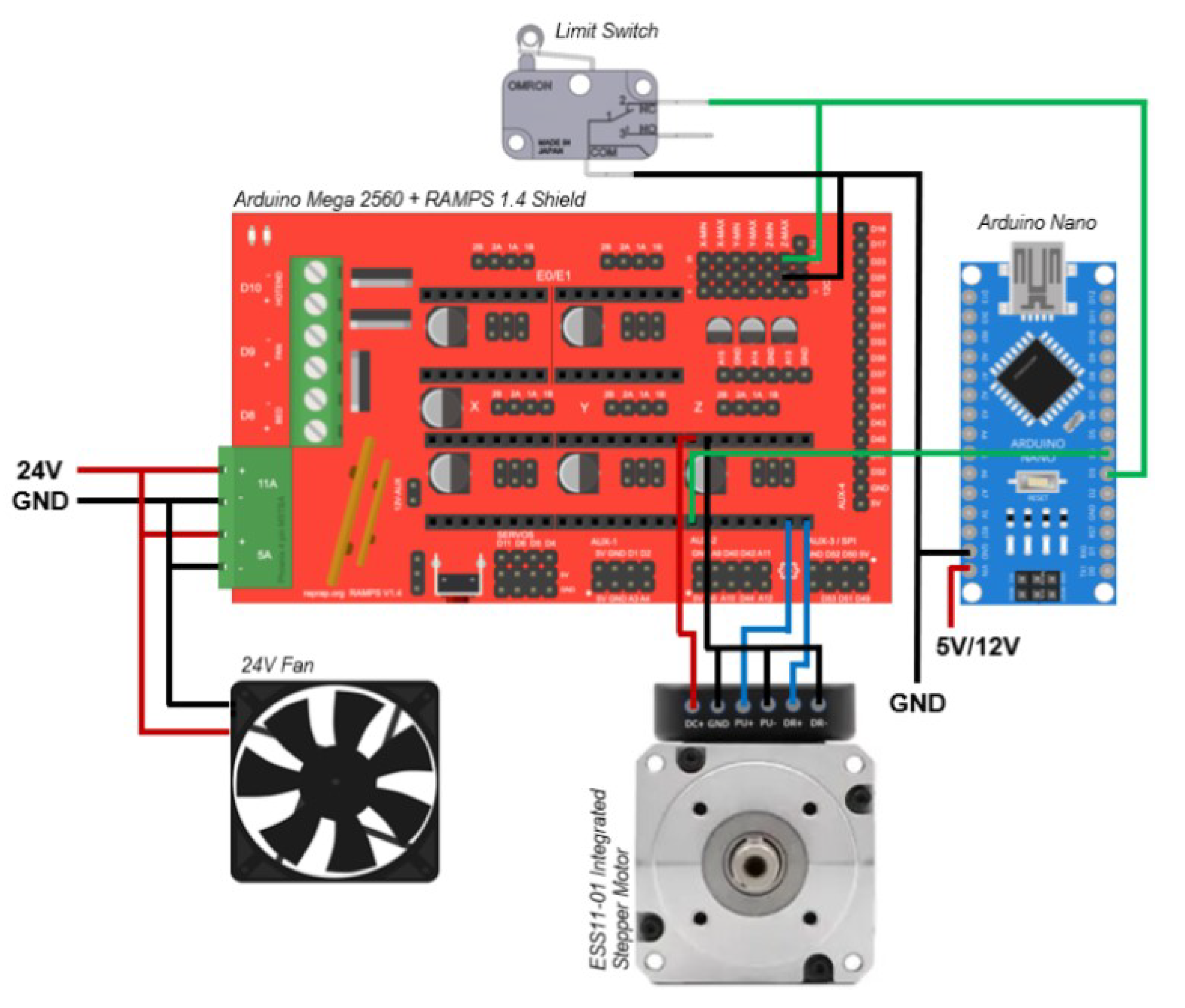
Figure 2.
Design of the light-based VP bioprinter. (A) General CAD model of the fully assembled system. (B) Z-axis module, (C) main stage, (D) vat-fixation mechanism, and (E) light source system.
Figure 2.
Design of the light-based VP bioprinter. (A) General CAD model of the fully assembled system. (B) Z-axis module, (C) main stage, (D) vat-fixation mechanism, and (E) light source system.
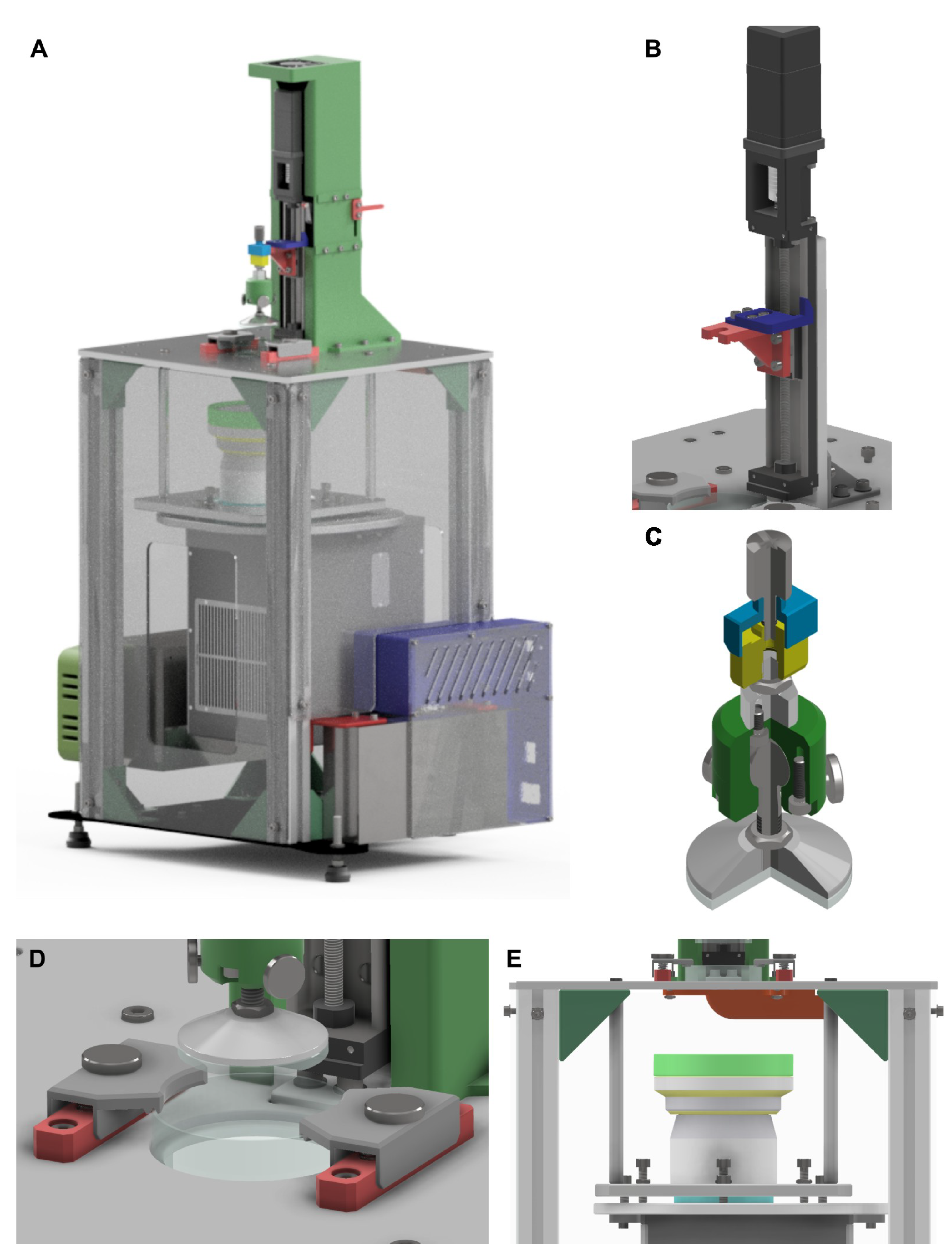
Figure 3.
Detail of the final prototype. (A) General view, (B) Z-axis system, (C) DLP supporting structure and (D) linear guide.
Figure 3.
Detail of the final prototype. (A) General view, (B) Z-axis system, (C) DLP supporting structure and (D) linear guide.
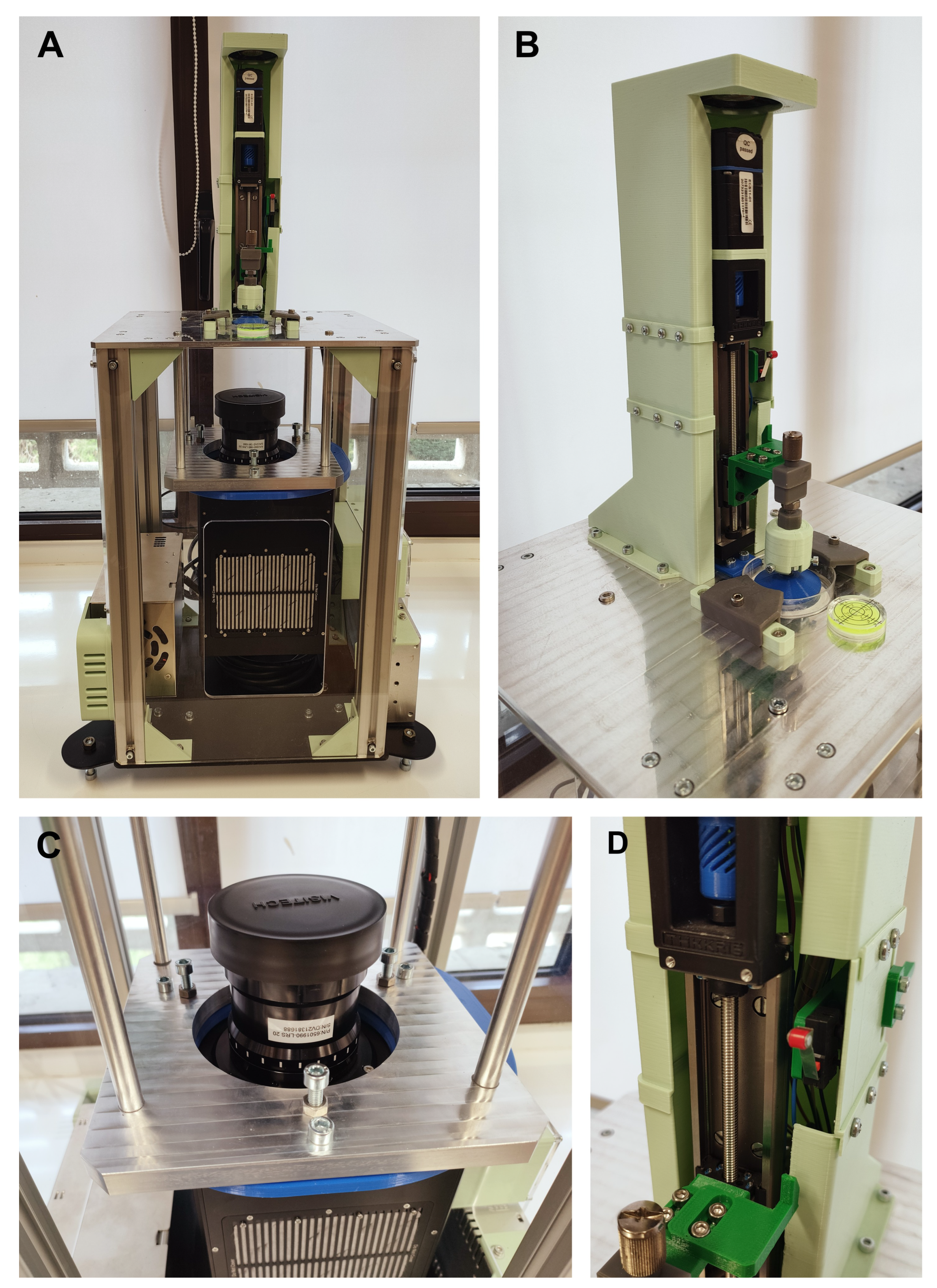
Figure 4.
Tolerance allocation on critical areas for the resolution of printing: (A) Projector assembly module and (B) Z-axis module.
Figure 4.
Tolerance allocation on critical areas for the resolution of printing: (A) Projector assembly module and (B) Z-axis module.
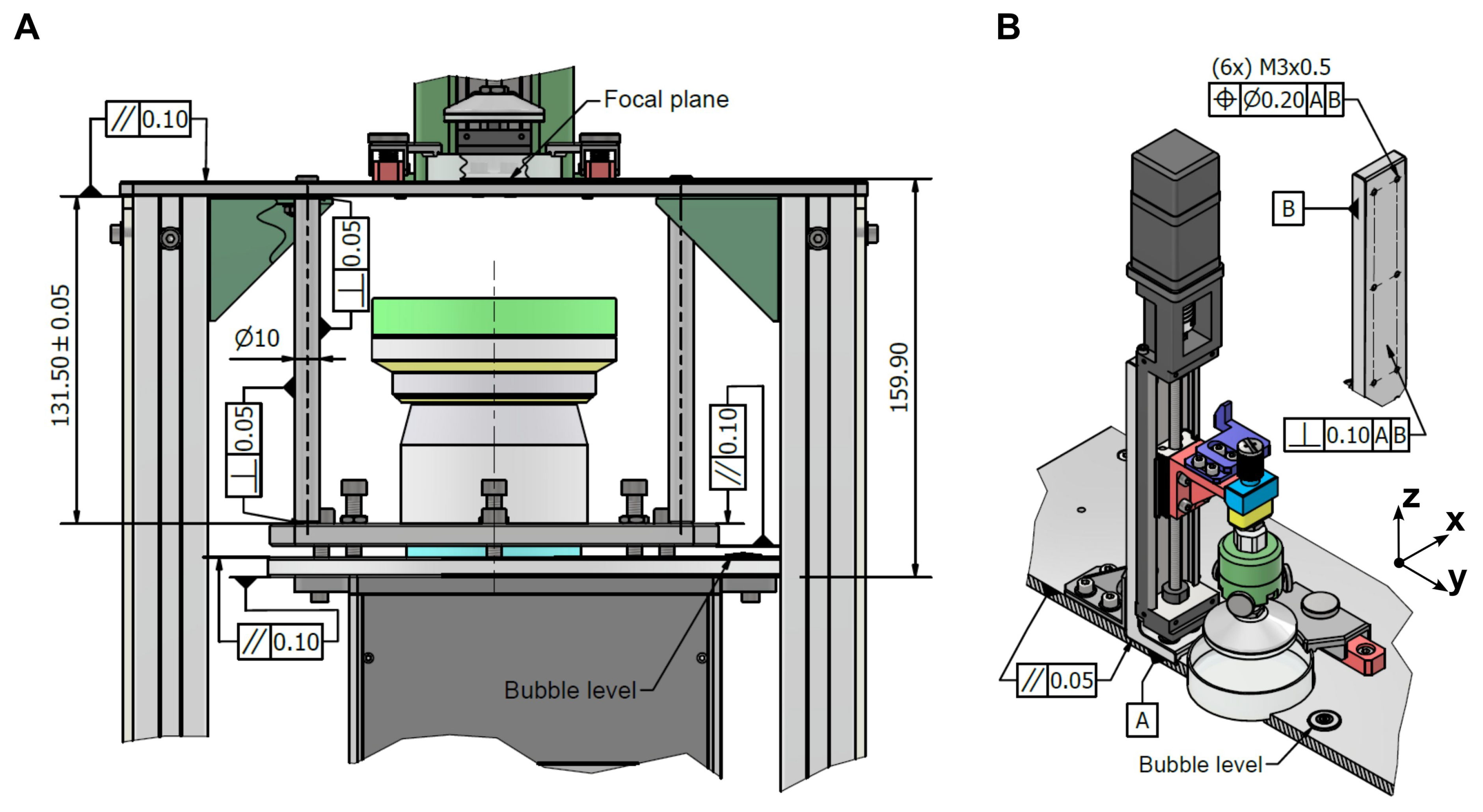
Figure 5.
Main menus of the open-source GUI software: (A) Auto Print, (B) Calibration, and (C) Manual Mode.
Figure 5.
Main menus of the open-source GUI software: (A) Auto Print, (B) Calibration, and (C) Manual Mode.
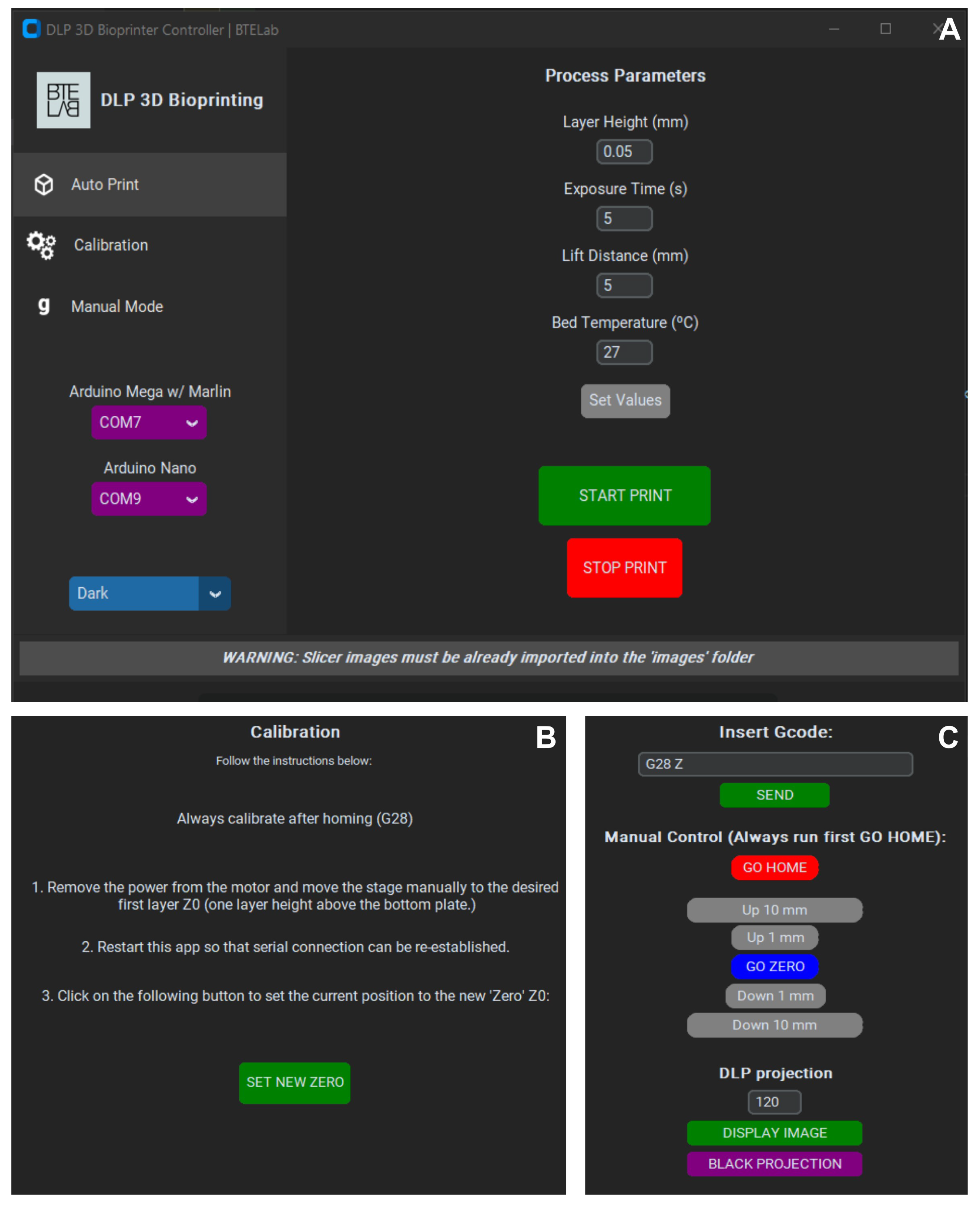
Figure 6.
Accuracy and repeatability tests. (A) Main setup for experimental work. (B) Representation of experimental data measured by the dial indicators.
Figure 6.
Accuracy and repeatability tests. (A) Main setup for experimental work. (B) Representation of experimental data measured by the dial indicators.
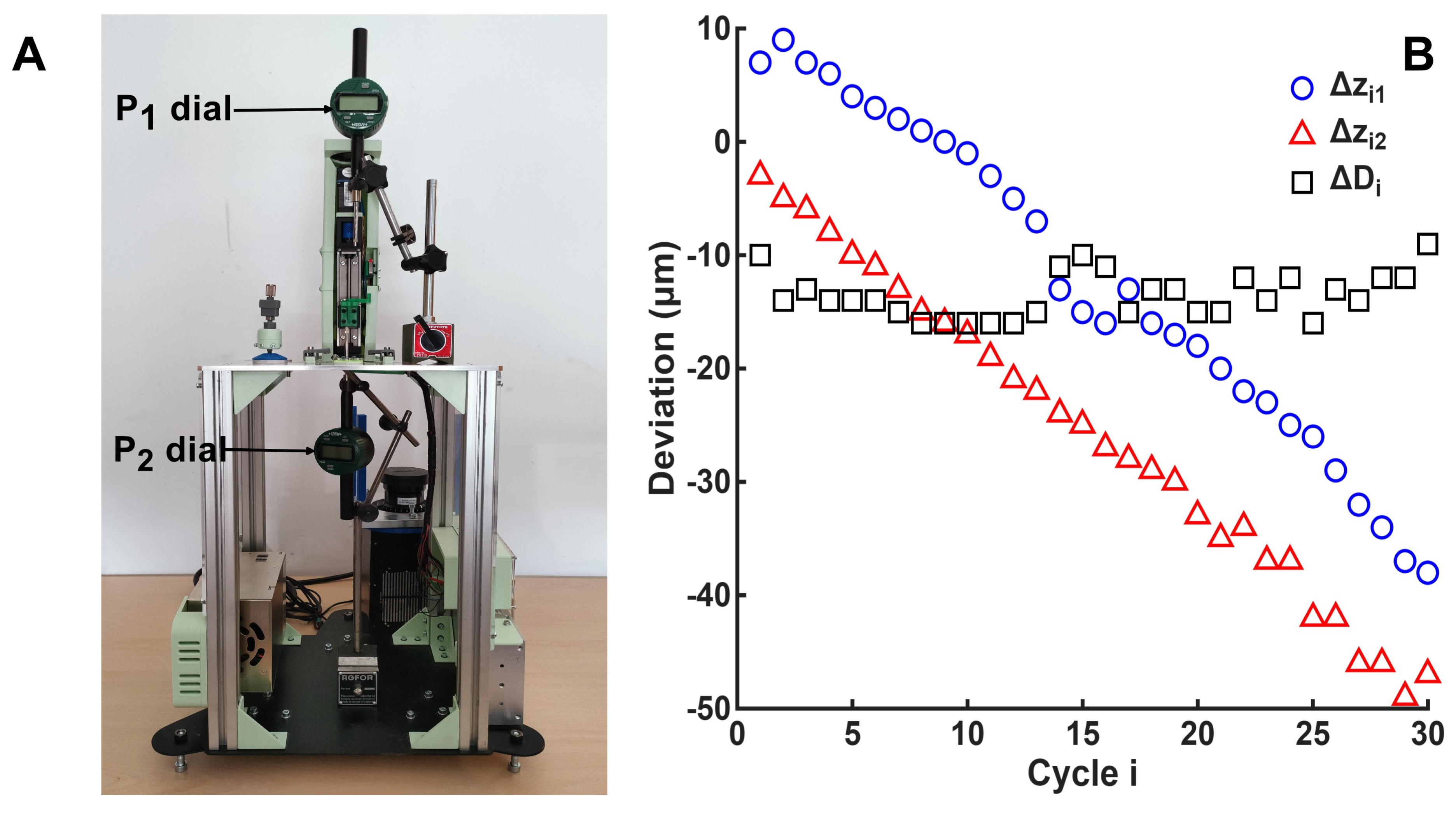
Figure 7.
Representative images of the microfluidic serpentine micro-channel model printed with the DLP. A ,B) Overview of the geometry; (C) detail of the device entrance; (D) detail of the printed layers.
Figure 7.
Representative images of the microfluidic serpentine micro-channel model printed with the DLP. A ,B) Overview of the geometry; (C) detail of the device entrance; (D) detail of the printed layers.
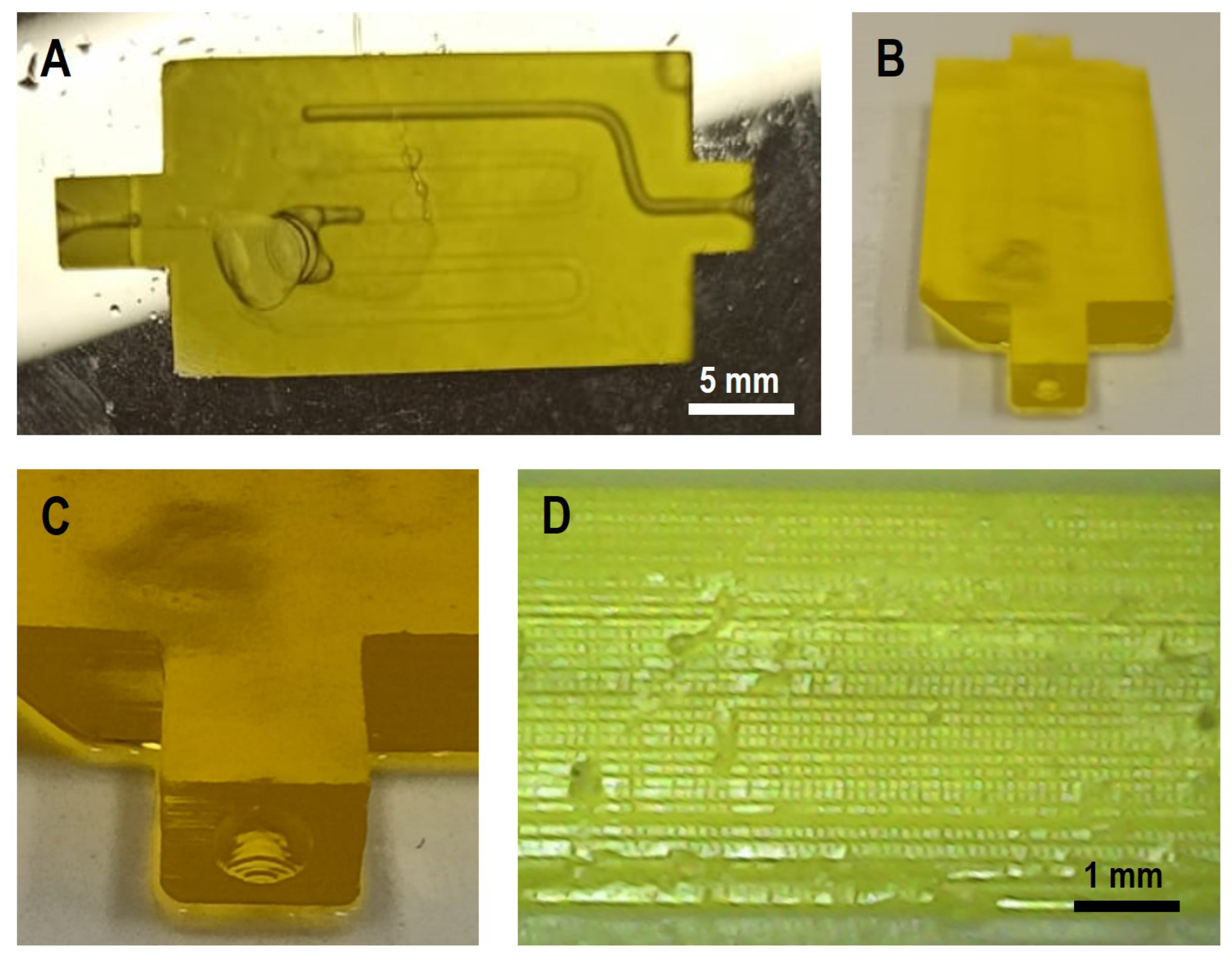

Table 1.
Operational parameters and main specifications of the bioprinting platform proposed in the design.
Table 1.
Operational parameters and main specifications of the bioprinting platform proposed in the design.
| Parameter | Value |
|---|---|
| XY resolution | (LRS-20), (LRS-WQm 1x) |
| XY dimension | 41.5 × (LRS-20), 14.7 × (LRS-WQm 1x) |
| Z resolution, | 5 |
| Z stroke, s | 50 |
| Light wavelength, | 405, 465 |
| Light power |
Table 2.
Geometrical tolerances and measurement results of critical components. Units in mm.
| Component | Tolerance | IT | Min. | Max. | Interval | Average | SD |
|---|---|---|---|---|---|---|---|
| Upper base | Parallelism | -0.031 | 0.013 | 0.044 | 0.049 | 0.006 | |
| 0.10 | -0.041 | 0.014 | 0.055 | ||||
| -0.040 | 0.009 | 0.049 | |||||
| Spacer braces | Perpendicularity | 0.05 | -0.002 | 0.009 | 0.011 | 0.012 | 0.002 |
| -0.017 | -0.003 | 0.014 | |||||
| -0.009 | 0.002 | 0.011 | |||||
| Upper frame | Parallelism | 0.10 | -0.012 | 0.003 | 0.015 | 0.016 | 0.001 |
| DLP | -0.017 | -0.001 | 0.016 | ||||
| -0.013 | 0.004 | 0.017 | |||||
| Lower frame | Parallelism | 0.10 | -0.029 | 0.022 | 0.051 | 0.048 | 0.003 |
| DLP | -0.024 | 0.025 | 0.049 | ||||
| -0.015 | 0.030 | 0.045 | |||||
| z-axis seat | Parallelism | 0.05 | -0.005 | 0.006 | 0.011 | 0.011 | 0.001 |
| (Upper base) | -0.007 | 0.005 | 0.012 | ||||
| -0.007 | 0.004 | 0.011 | |||||
| Z-axis frame | Perpendicularity | 0.10 | -0.067 | 0.009 | 0.076 | 0.063 | 0.023 |
| Datum A | 0.000 | 0.036 | 0.036 | ||||
| -0.016 | 0.060 | 0.076 | |||||
| Z-axis frame | Perpendicularity | 0.10 | -0.012 | 0.023 | 0.035 | 0.038 | 0.003 |
| Datum B | -0.015 | 0.022 | 0.037 | ||||
| -0.014 | 0.027 | 0.041 |
Table 3.
Dimensional tolerance and measurement results of the Spacer brace. Units in mm.
| Dimension | Nominal | IT | Min. | Max. | Measured | Average | SD |
|---|---|---|---|---|---|---|---|
| Length | 172.8 | 0.05 | 172.75 | 172.85 | 172.82 | 172.817 | 0.006 |
| 172.81 | |||||||
| 172.82 |
Disclaimer/Publisher’s Note: The statements, opinions and data contained in all publications are solely those of the individual author(s) and contributor(s) and not of MDPI and/or the editor(s). MDPI and/or the editor(s) disclaim responsibility for any injury to people or property resulting from any ideas, methods, instructions or products referred to in the content. |
© 2025 by the authors. Licensee MDPI, Basel, Switzerland. This article is an open access article distributed under the terms and conditions of the Creative Commons Attribution (CC BY) license (http://creativecommons.org/licenses/by/4.0/).
Copyright: This open access article is published under a Creative Commons CC BY 4.0 license, which permit the free download, distribution, and reuse, provided that the author and preprint are cited in any reuse.


