Preprint
Article

This version is not peer-reviewed.

Enhanced Magneto-optical Kerr Effects by Micron Array Thin Films with Organic-Inorganic Interface

A peer-reviewed article of this preprint also exists.

Submitted:

25 November 2024

Posted:

26 November 2024

You are already at the latest version

Abstract

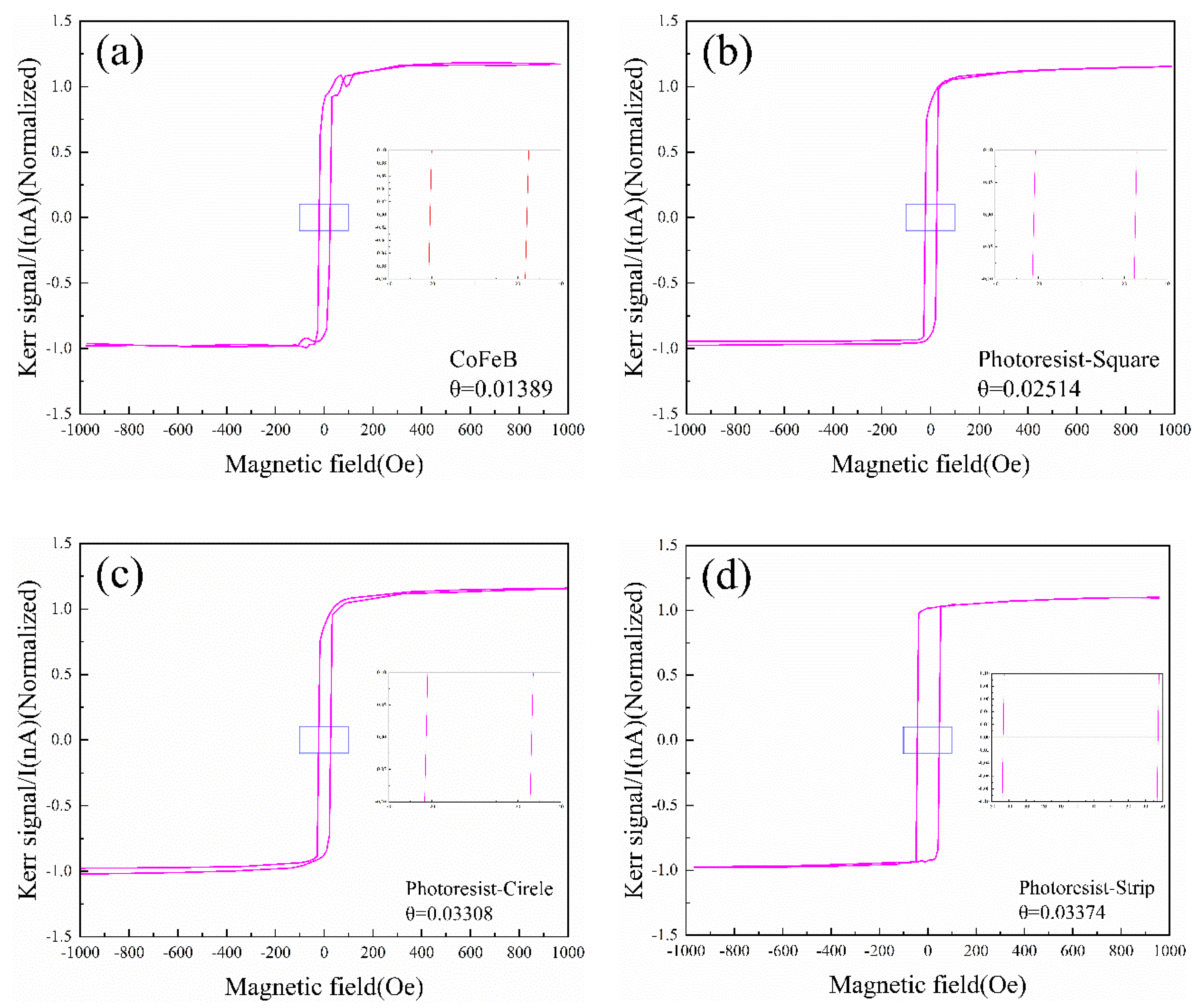
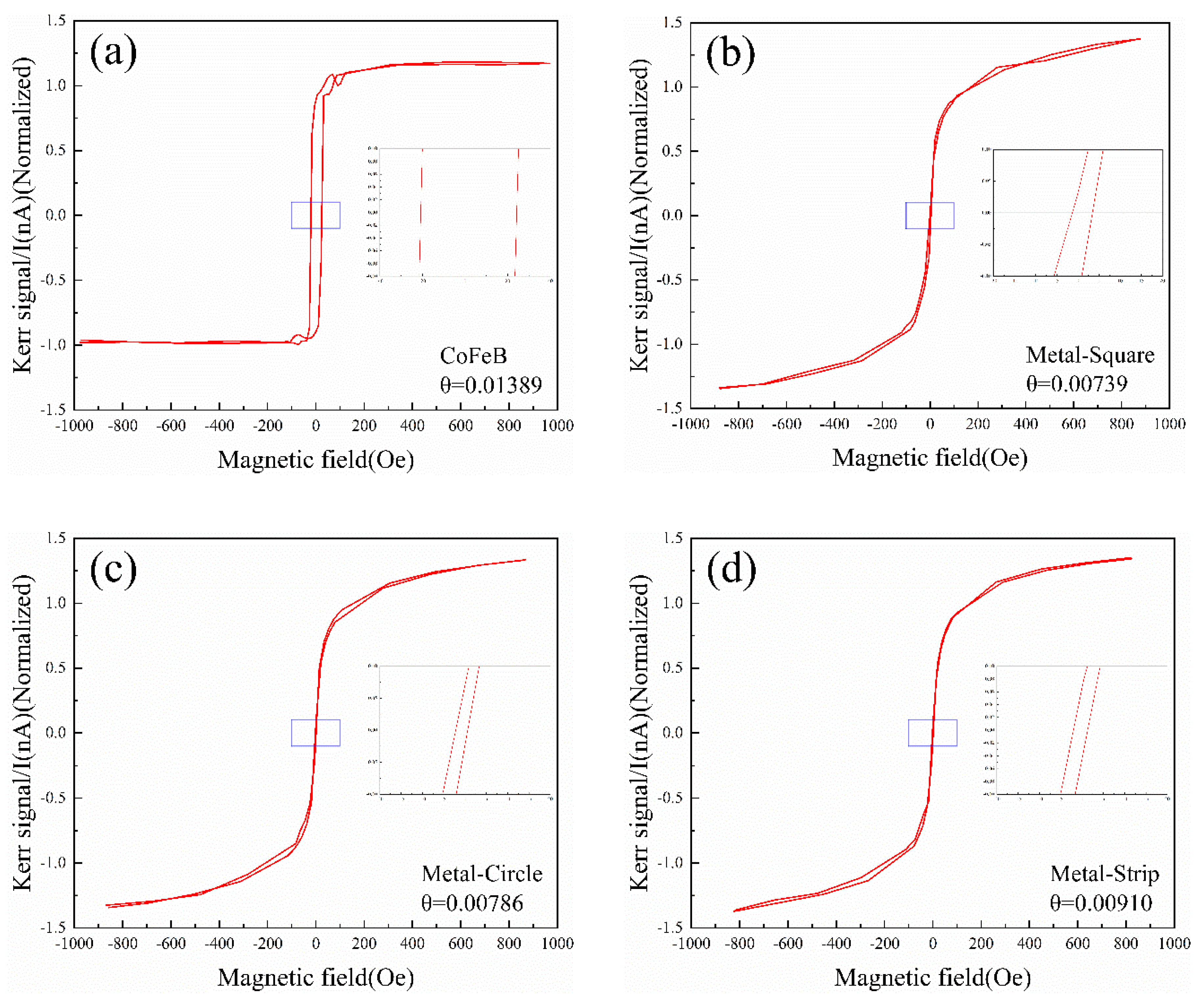
The modulation of the magneto-optic signal is a crucial research focus in the field of magneto-optics. Micron array of varying shapes were fabricated using the UV exposure technique, and test their effects on the magneto-optical Kerr response of CoFeB thin films. The influence of the organic-inorganic interface on the magneto-optical Kerr effect was investigated by utilizing organic materials to fabricate arrays. The results indicate that the micron-scale metal array exhibits a limited enhancement of the magneto-optical Kerr signal, but it can change the ferromagnetic strength and the magnetization speed of the magnetic layer. Because the electron orbit coupling at the organic inorganic interface enhances the performance of the magnetic film. When the photoresist is used as the array material, the longitudinal magneto-optical Kerr signal of the CoFeB film increases by at least 2 times. The enhancement effect of different shapes of arrays is different because of the different contact area with CoFeB.

Keywords: 
;  ;  ;  ;  

1. Introduction

The magneto-optical effect, as an important bridge connecting magnetism and optics, offers broad application prospects for the development of information storage[1], sensing technology and optoelectronic devices. Thin films exhibiting high magneto-optical coefficients are applicable in the development of magneto-optical isolators[2], modulators[3], and memories, as well as for biological organic molecule concentration calibration[4] and weak magnetic field detection[5]. This includes materials such as transition metal sulfides, rare earth-transition metal alloy thin films, and doped rare earth garnets. The control of a material alone does not suffice to achieve a significant increase in the amplitude of the magneto-optical coefficient. The essence of the magneto-optical Kerr effect lies in the coupling interaction between spin-orbit coupling and electromagnetic wave among electrons within a materia[6,7]. Through this mechanism, we can manipulate the morphology of materials by constructing microstructures or nanostructures to enhance the interaction between light and matter, thereby further enhancing their magneto-optical properties[8]. With the continuous advancement of nanotechnology and micro-machining technology, precise regulation of the magneto-optical characteristics of magnetic films at the micron level and even smaller scales has become achievable. The unique size effect and regulability contribute to the distinctive and noteworthy magneto-optical properties exhibited by magnetic thin film[9].
The doping of organic materials has demonstrated significant functional advantages in numerous applications[10]. For instance, in optoelectronic devices, such materials can substantially enhance the energy conversion efficiency of solar cells and light-emitting diodes (LEDs)[11]. Moreover, they also find extensive utility in catalysis[12,13], magnetic materials[14,15], biological materials[15], among others. Particularly noteworthy is the attention garnered by organic-inorganic hybrid materials for their distinctive structural and performance advantages when employed in sensors[16,17,18]. Therefore, the introduction of organic-metal interface provides a new dimension for regulating the magneto-optical effect of magnetic thin films. The strength of interfacial coupling between organic molecules and ferromagnetic metals significantly influences spin polarization. Orbital hybridization takes place at the interface between the organic molecule and the ferromagnetic electrode, leading to an unequal state density of upper and lower spins at the Fermi level and formation of a novel metal-organic interface state[19]. This interface state enables spin filtering, thereby exerting a substantial impact on spin signal. For instance, in LSMO/Alq3/Co magnetic tunnel junctions, due to orbital hybridization between the ferromagnetic electrode and organic molecule at the interface, magnetoresistivity exceeding 300% is observed with a negative magnetic response[20]. Therefore, this interface coupling effect offers a novel avenue for the design and optimization of emerging magnetic materials, while also presenting a fresh perspective to enhance the magneto-optical properties of materials.
The Magneto-optical Kerr effect is a crucial technique for investigating surface magnetism and is widely employed in measuring magnetic anisotropy, magnetic order, and coupling of multilayer films. It enables deep probing into the magnetic properties of materials, providing essential experimental means and theoretical foundations for research in related fields. The essence of magneto-optical effect is spin-orbit coupling effect[21]. Through the spin-orbit coupling interaction, the light in the magnetic field generates another component in a direction perpendicular to the original polarization plane, thus changing the polarization state of the light. Numerous studies have emphasized the significance of spin–orbit coupling on magneto-optical effects and have shown that stronger spin–orbit coupling typically leads to a more significant influence on the magneto-optical effects. Therefore, to investigate the magneto-optical properties of materials, it is necessary to consider the magnetic and spin–orbit coupling effects.
To date, extensive research has been conducted on various nanostructures, such as periodic rectangular apertures[6], optical Tam-state structures[22,23], and prism-coupled surface plasmon resonance systems[24,25], in order to enhance the magneto-optical Kerr effect by leveraging stronger spin-orbit coupling effects. However, it should be noted that the fabrication process of these nanostructures is both costly and time-consuming[26,27]. The present study employs ultraviolet exposure technology to fabricate a simplified micron array structure, thereby modifying the surface morphology of the magnetic thin film and enhancing the interaction with the surface field, ultimately achieving control over the magneto-optical Kerr effect. Simultaneously, an organic molecular medium is introduced to form an organic-inorganic interface, harnessing the coupling effect at the organo-metal interface to augment spin-orbit interaction within the magnetic layer and consequently enhance the magneto-optical Kerr effect.

2. Experimental Section

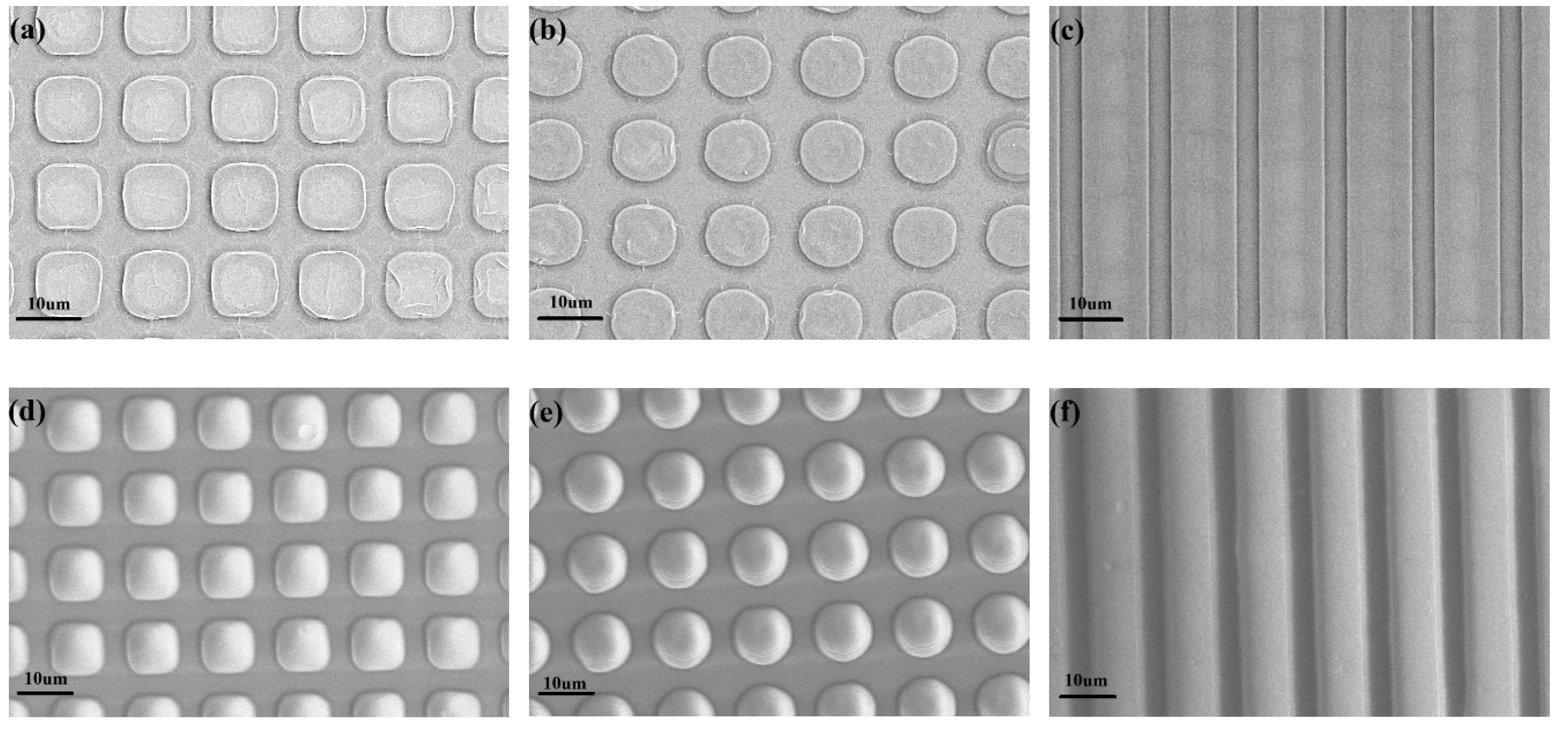
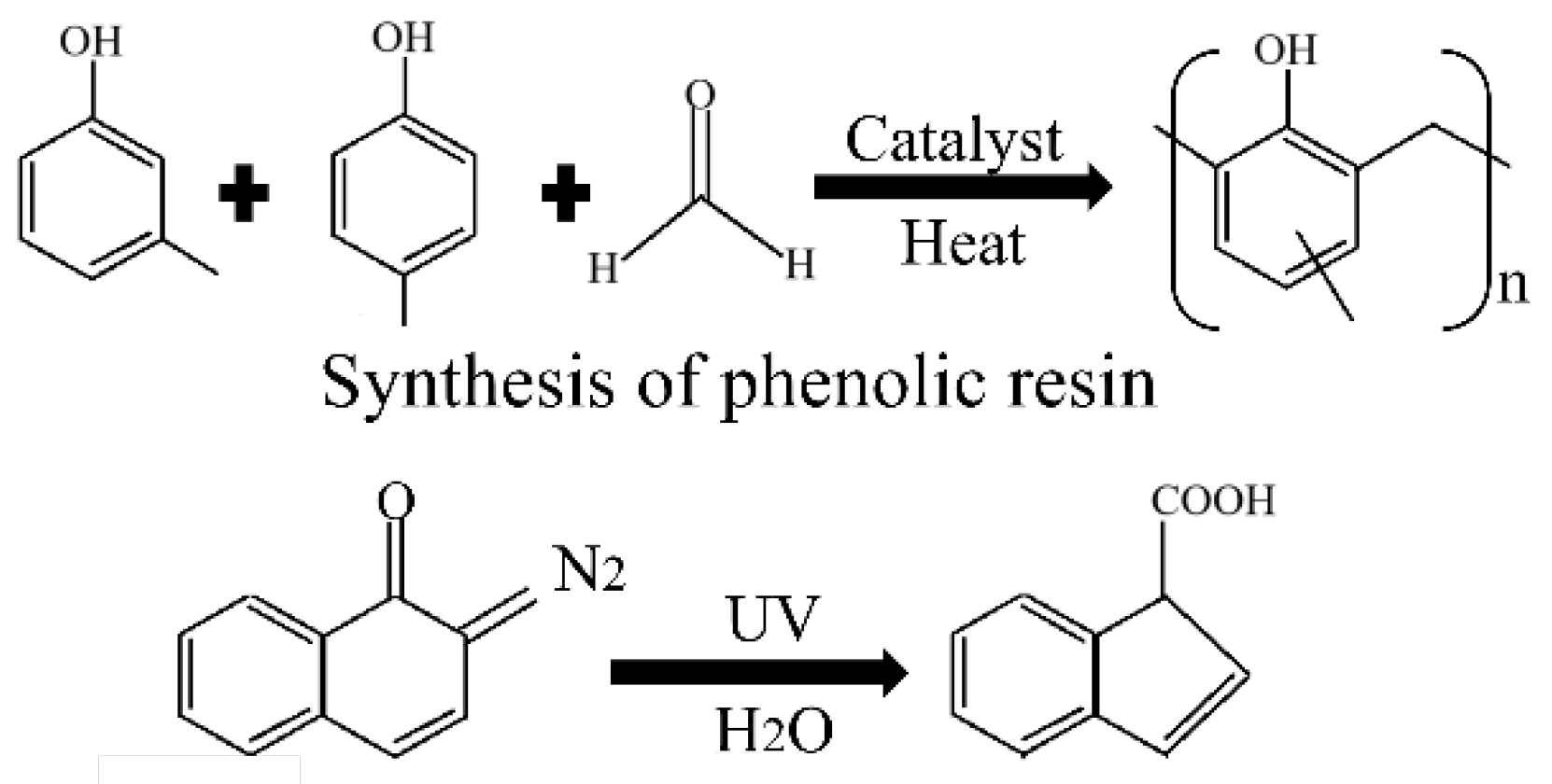
2.1. Preparation of Micrometer Arrays

The H94-17G mask exposure machine (Sichuan Nanguang Vacuum Technology Co., LTD.) was utilized for the UV exposure experiment. A GCQ200Z DC high-pressure spherical mercury lamp with a center wavelength of 365nm served as the light source, and contact exposure was employed.
The experiments were carried out on monocrystalline silicon wafer with the size of 1*1cm. Cr film was deposited on silicon wafer by magnetron sputtering technology as the etching layer. During sample preparation, the vacuum level of the magnetron sputtering chamber was uniformly set to 9.8 × 10⁻⁴ Pa, and the argon gas flow was 40 sccm. The Cr layer adopts the method of DC sputtering, the power provided is 30 W, and the gas pressure in the argon atmosphere is at 1 Pa during the sputtering process.
The sample surface was coated with S1813 photoresist at a standard concentration and spun at 2500 rpm. The coated sample was baked on a hot plate at 115 °C for 60 s. After cooling, the sample was placed on an exposure table and covered with a mask. The exposure time was set, and the energy used for exposure was 150mj/cm2. Following exposure, the sample underwent immersion in standard ZX-238 developer at room temperature for 30s before being rinsed with deionized water for another 30s. Finally, it was baked again at 125℃ for 120s. An array pattern formed by the photoresist is formed on the sample surface.
The sample containing the etched layer is wet-etched to produce the metal pattern after development. The developed sample was immersed in LN-937 etching solution for a duration of 3 seconds, swiftly removed, and subsequently rinsed with deionized water multiple times to eliminate the etching solution. It is then subjected to drying and immersion in N-methylpyrrolidone (NMP) to eradicate any residual photoresist. Finally, it undergoes rinsing and drying processes to obtain the desired metal pattern.
The CoFeB (70nm) magnetic layer was deposited onto the sample with the pre-existing pattern using radio frequency sputtering, the power provided is 100 W, and the gas pressure in the argon atmosphere is at 0.1 Pa during the sputtering process. Finally, we get two kinds of samples with metal and photoresist as pattern layers, and the magnetic layer on the surface of the sample is continuous.
At the same time, we made samples with non-continuous magnetic layers. The sample with Cr and CoFeB was etched to obtain the array pattern of independent magnetic layers.

2.2. Magneto-Optical Kerr Test System

The self-assembled longitudinal magneto-optic Kerr test system was used to perform the magneto-optic testing. A semiconductor laser with a wavelength of 450nm and an output power of 40 mW is used as the light source. First, the extinction position was determined by adjusting the polarizer and analyzer’s polarization direction. The analyzer is then rotated so that it deviates from the extinction position by a small angle δ. The approximate extinction position, instead of the complete extinction position, is used to distinguish between the positive and negative Kerr rotation angles. At the approximate extinction position, the light passing through the analyzer has a background intensity I0. The intensity over time of the rotation direction of the polarization plane of the reflected light increases in the same direction as δ, and decreases in the opposite direction. In such a way, the magnetization direction of the sample can be distinguished by a change in the light intensity. In this paper, the deflection angle δ is uniformly set at 0.2°. Usually we use equation 1 to calculate the Kerr rotation Angle[28].
θ k = 1 2 θ k + θ k = δ 4 I + M Z I M Z I 0 = δ 4 I I 0                                      
The laser light passes through the polarizer and is converted into light that is linearly polarized. The light is reflected by the sample in the magnetic field and passes through the polarizer to enter the photodetector. The optical signal is converted into an electrical signal by a photodetector and the input passes to a diode amplifier for amplification purposes. At the same time, the magnetometer detects the magnetic field size signal and converts it into an electrical signal. The two signals are synchronously input into the computer and combined into a data graph of the magneto-optical Kerr signal in the test software.

3. Results and Discussion

3.1. Characterization of Micron Structure

Shown in Figure 1 is a micrometer-scale array image taken with a scanning electron microscope(FE-SEM,SPRA55). The array of Cr metal formed after etching is depicted in Figure 1 (abc). The figure demonstrates that the etched metal array exhibits a distinct edge, a uniform pattern distribution, and the size is highly consistent. The three arrays all have a periodicity of 14 microns. At the same time, it is obvious that the area proportion of the three arrays is different. The strip array occupies the largest area per unit area, while the square array occupies the smallest area.
Figure 1(def) shows an image of the array formed by the photoresist. The photoresist array has the same period as the Cr metal array. The area ratio of the differently shaped arrays formed by the two materials remains consistent on a two-dimensional plane. The results, however, significantly vary when considering the three-dimensional. Because the collimation of light affects the photoresist during exposure, it also alters the contrast of the developed pattern. The electron microscope images of the photoresist array clearly indicate that each graphic surface exhibits a curved protrusion. The protrusion offers an expanded surface area.

3.2. Longitudinal Magneto-Optical Kerr Effect Test for the Metal Array

The longitudinal magneto-optical Kerr effect of a composite continuous CoFeB film with an array of Cr metal was tested. The Figure 2 presents the test results of the longitudinal magneto-optical Kerr effect for different arrays. The saturation magneto-optical Kerr rotation angle of the CoFeB is 0.01389°. The saturation magneto-optical Kerr rotation angle of the square array is 0.00739°, that of the circular array is 0.00787°, and that of the strip array is 0.00909°. In terms of array applications, the saturated magneto-optical Kerr effect signals are weakened compared with pure CoFeB films. The likely reason is that the array alters the intensity of the electromagnetic field in close proximity to the magnetic layer. The Jones matrix of the magneto-optical Kerr effect can be written as[29,30]:
E s r E p r = r p p r s p r p s r s s E s i E p i                                                          
which assumes that the incident light is P-polarized. Following the introduction of a magnetic field, the polarization state of the reflected light changes, and an additional S component appears. The longitudinal magneto-optical complex Kerr angle can be defined as:
θ k = θ + i η = r p s / r p p                                                    
where r p s is the reflection coefficient of the conversion of the P light into S light, and r   p p is the pure optical effect that represents the change of the reflectivity of the P light itself. It can be seen that the magneto-optical response can be improved by increasing the reflection coefficient of r p s for the P light converted into S light or by reducing the reflectivity r   p p . The magneto-optical polarization conversion rate r p s of a ferromagnetic layer film with a thickness of d can be written as:
r p s E P E S d ε m o                                                        
where E P E S is the average value of the product of the field components inside the magnetic layer, normalized to the incident light intensity, and   ε m o is the magneto-optical constant of the material. The incident light reflected by the array will diffract, which is called Fraunhofer diffraction. The diffraction will weaken the surface localized electromagnetic field of the magneto-optical thin film, which makes the average E P E S smaller. This results in a reduction in the magneto-optical polarization conversion rate r p s , thereby weakens the saturation magneto-optical Kerr signal.
Several studies indicate that the demagnetizing field is affected by the spacing between arrays[31,32]. Therefore, it can be seen from Figure 3 that the demagnetizing field of the sample with array increases, and the results of the three figures tend to be consistent. At the same time, because of diffraction magneto-optical effect is more affected by the array than the reflection magneto-optical effect[32]. The larger submicron array spacing will reduce coercivity in the diffraction magneto-optical effect signal. In the test, the reflected signal and the diffraction signal are received at the same time. Therefore, the hysteresis loop obtained after the reflection signal and the diffraction signal are received at the same time will show a larger demagnetizing field and a smaller coercive force.
At the same time, the hysteresis loop of diffractive magneto-optical Kerr effect becomes more tilted with the increase of array spacing[32]. This means that the saturation magnetization is reduced and the difference in the magneto-optical signal is reduced. Finally, the saturation magneto-optical Kerr rotation angle decreases.

3.3. Longitudinal Magneto-Optical Kerr Effect Test for the photoresist Array

The energy level structures of organic and inorganic materials exhibit distinct disparities. Inorganic materials possess valence and conduction bands, where electrons are delocalized, while organic materials have discrete energy levels encompassing the highest occupied molecular orbital(HOMO) and the lowest unoccupied molecular orbital(LUMO)[33]. Organic molecules attract each other through van der Waals forces, which can result in the formation of amorphous, polycrystalline, or single crystals depending on the molecular arrangement. Due to their weaker compared to covalent and ionic bonds, organic materials exhibit softer properties than inorganic materials. However, the orbital overlap between organic molecules is typically limited, impeding electron delocalization and resulting in poor electrical conductivity of organic materials. Based on the extent of orbital overlap, there are generally two modes of transport observed in organic materials: band-like transport and hopping transport[34]. When the π orbitals exhibit significant overlap, the electrons become delocalized within the energy level, resulting in the formation of a quasi-continuous state. During this period, electron transportation can occur through banded transport mechanisms, such as TTF-TCNQ[35]. When the degree of overlap is weak, electrons undergo jump transport from one molecule's local state to another, which can be described as phonon-assisted tunneling. This mode of charge transport is commonly observed in organic molecules, such as the electron of Alq3 jumps between local states[4]. When organic matter is in proximity to a metal, their energy levels change accordingly[36]. The energy level changes, the energy level of organic molecules at the interface, the 3d band structure of the transition metal, s and d bands, anisotropy, and other factors need to be taken into consideration[37].
The magnetic properties of transition metals mainly arise from the spatial localization of the d orbital near the top of the d band, which not only results in a high density of states near the Fermi energy but also leads to a relatively large exchange correlation integral, satisfying the Stoner ferromagnetic criterion[38]. Therefore, if the delocalized electrons formed by the large overlap of π orbitals in organic molecules interact with the D-orbital electrons of transition metals, it is possible to alter the magnetic properties of metals and induce a magneto-optical effect at the interface[39,40].
According to macroscopic dielectric theory, the magneto optical effect is caused by an asymmetry in the off-diagonal element of the dielectric tensor of the material[41]. In microscopic quantum theory, the essence of the magneto-optical effect is thought to lie in the interactions between the electric field of the input light and the electron spin, i.e. via spin–orbit couplings. The connection between the two is that the macroscopic dielectric tensor determines the optical properties of the matter, while the dielectric tensor itself is determined by the microscopic electron motion. The off-diagonal component of the dielectric tensor, which appears after the application of the magnetic field, is the result of the spin–orbit coupling effect. The extent of spin-orbit coupling can be quantified through its Hamiltonian as:
H S O = μ S B = Z e g μ B 8 π ε 0 m c 2 r 3 L S                                              
where Z is the atomic number, e is the elementary charge, g is the Lande factor, µB is the Bohr magneton, ε0 is the vacuum permittivity, m is the mass of the electron, r is the radial vector of the electron pointing to the nucleus, S is the spin angular momentum, and L is the orbital angular momentum of the electron moving around the nucleus. Clearly, the spin-orbit coupling can be enhanced by modifying the charge number and the vector product of spin angular momentum and orbital angular momentum. It can be done by combining organic molecules with metals. The orbital angular momentum of organic aromatic compounds plays a crucial role in addressing this challenge. The magnitude of the orbital angular momentum is associated with the magnetic quantum number m. In organic aromatic compounds, the π molecular orbitals are quantized in terms of m (similar to atomic orbitals), and the maximum |m| value of these π molecular orbitals increases as the size of the π-conjugated system expands[42]. Therefore, in the experiment, we used the photoresist with organic aromatic compounds as the interface material to explore its influence on the magneto-optical effect.
The test results of the longitudinal magneto-optical Kerr effect of the photoresist array are shown in Figure 3. The saturation magneto-optical Kerr signal of the photoresist-based samples showed a significant enhancement.
Figure 3. Longitudinal magneto-optical Kerr signal test data for the photoresist array(a)CoFeB (b) square (c) circle (d) strip.
Preprints 140750 g003
The photoresist used in the experiment is a positive-type photoresist, with its primary constituent being linear phenolic resin. The phenolic resin imparts adhesion and chemical resistance to the photoresist. The phenols used in the preparation of phenolic resin are phenol, cresol, xylenol, resorcinol, commonly used phenol; Aldehydes are formaldehyde, furfural and so on[43]. Figure 4 shows the structural formula of the simplest and most common phenol-formaldehyde resin. The phenolic resins synthesized from various raw materials have different functional groups, including carbonyl and carboxyl groups, but the main body is a long chain with a large number of benzene rings. Therefore, phenolic resin is a large π-coupled system with a large orbital angular momentum. So, the spin-orbit coupling is enhanced at the organic-inorganic interface due to the increase of orbital angular momentum. And then it can also be seen from the test results that the magneto-optical Kerr signal enhancement of the array with the largest metal contact area per unit area is the largest.
Each of the six carbon atoms in the benzene ring has an unhybridized 2p orbital, which is perpendicular to the plane of the benzene ring and overlaps with each other from the side to form a closed π bond. The electrons in the p bond are no longer owned by a single atom, but move delocalizedly over the entire large π bond, so they are also referred to as delocalized π bonds. The feature of a π bond lies in the dispersion of electron density surrounding the bonding atoms, rather than its concentration between the two nuclei. Consequently, the attractive force exerted by the atomic nucleus on the π electron is relatively weak, allowing for unrestricted movement of the π bond's electron cloud within the molecule and its distribution among multiple atoms.
The coupling of π-d electrons occurs at the interfaces between organic and metal materials. The interaction between the delocalized p orbital electrons of the PI bond and the 3d orbital electrons of the transition metal in the magnetic layer enhances spin-orbit coupling at the interface[44]. This electron coupling enhances the interaction between incident light and the magnetic layer, thereby significantly improving the saturation deflection angle signal of the magneto-optical Kerr effect.
In addition, Figure 3 shows that the saturation magneto-optical Kerr signals of arrays with different shapes are also different. The variation in the test signal arises from the disparity in contact area between the organic molecule and the magnetic metal layer, which is attributed to the distinct surface area resulting from different shapes of the photoresist array. The larger the contact area between the metal and the organic material, the more temporary or permanent bonds will be formed with the organic material during the metal deposition process. In this way, the coupling in organic-inorganic interfaces has a greater influence on the magneto-optical Kerr effect.

4. Conclusion

In this paper, a simpler and more affordable micron-scale array is prepared for regulating the longitudinal magneto-optical Kerr signal. In this work, we design arrays of three shapes that have a slight weakening of the longitudinal saturation magneto-optical Kerr signal of CoFeB magnetic films deposited on the surface. The micrometer-scale array cannot change the effect of spin orbit coupling of the magnetic film at the microscopic level, but it can regulate the optical signal at the macroscopic level.
Simultaneously, we introduce organic materials and use the coupling of organic-inorganic interface to further change the longitudinal saturation magneto-optical Kerr signal of the CoFeB film. The coupling of electron orbits between organic molecules and metals can enhance the spin-orbit coupling effect of magnetic thin films, and then regulate the magneto-optical Kerr signal.
Therefore, this work provides more research ways for us to regulate magneto-optical signals. The modulation and enhancement of magneto-optical signals can be realized by making efficient microstructures and organic-inorganic hybrid materials with stronger electron orbital coupling.

References

  1. Lambert, C.-H.; Mangin, S.; Varaprasad, B.S.D.C.S.; Takahashi, Y.K.; Hehn, M.; Cinchetti, M.; Malinowski, G.; Hono, K.; Fainman, Y.; Aeschlimann, M.; et al. All-Optical Control of Ferromagnetic Thin Films and Nanostructures. SCIENCE 2014, 345, 1337–1340. [CrossRef]
  2. Fang, K.; Yu, Z.; Liu, V.; Fan, S. Ultracompact Nonreciprocal Optical Isolator Based on Guided Resonance in a Magneto-Optical Photonic Crystal Slab.
  3. Irvine, S.E.; Elezzabi, A.Y. A Miniature Broadband Bismuth-Substituted Yttrium Iron Garnet Magneto-Optic Modulator. J. Phys. Appl. Phys. 2003, 36, 2218. [CrossRef]
  4. Colombelli, A.; Manera, M.G.; Borovkov, V.; Giancane, G.; Valli, L.; Rella, R. Enhanced Sensing Properties of Cobalt Bis-Porphyrin Derivative Thin Films by a Magneto-Plasmonic-Opto-Chemical Sensor. Sens. Actuators B Chem. 2017, 246, 1039–1048. [CrossRef]
  5. Belyaev, V.K.; Rodionova, V.V.; Grunin, A.A.; Inoue, M.; Fedyanin, A.A. Magnetic Field Sensor Based on Magnetoplasmonic Crystal. Sci. Rep. 2020, 10, 7133. [CrossRef]
  6. Zhang, W.; Wang, Q.; Zhao, C.; Song, Y. The Optical Cavity Enhanced Magneto-Optical Kerr Effect Signals of AAO/Al-Based CoFeB Nanostructure Arrays. Opt. Commun. 2019, 437, 44–49. [CrossRef]
  7. Zhang, W.; Li, J.; Ding, X.; Pernod, P.; Tiercelin, N.; Song, Y. Tunable Magneto-Optical Kerr Effects of Nanoporous Thin Films. Sci. Rep. 2017, 7, 2888. [CrossRef]
  8. Lou, P.; Wu, Q.; Zhang, C.; Wang, Z.; Song, Y. Enhanced Magneto-Optical Kerr Effect via the Synergistic Effect of Surface Plasmon Resonance and Spin–Orbit Coupling in Au@Pt Nanohybrid Layers. J. Phys. Appl. Phys. 2023, 56, 375001. [CrossRef]
  9. Wang, Z.; Cui, X.; Zhu, R.; Li, J.; Zhang, B.; Song, Y. Hybrid Magneto-Plasmonic Structure Consisting of Hexagonal Periodic Nanodisks Array with Giant Transverse Magneto-Optical Kerr Effect for Sensing Application. J. Phys. -Appl. Phys. 2024, 57, 355004. [CrossRef]
  10. Ostroverkhova, O. Organic Optoelectronic Materials: Mechanisms and Applications. Chem. Rev. 2016, 116, 13279–13412. [CrossRef]
  11. Hussain, R.; Mehboob, M.Y.; Khan, M.U.; Khalid, M.; Irshad, Z.; Fatima, R.; Anwar, A.; Nawab, S.; Adnan, M. Efficient Designing of Triphenylamine-Based Hole Transport Materials with Outstanding Photovoltaic Characteristics for Organic Solar Cells. J. Mater. Sci. 2021, 56, 5113–5131. [CrossRef]
  12. Bodaghifard, M.A.; Hamidinasab, M.; Ahadi, N. Recent Advances in the Preparation and Application of Organic-Inorganic Hybrid Magnetic Nanocatalysts on Multicomponent Reactions. Curr. Org. Chem. 2018, 22, 234–267. [CrossRef]
  13. Najahi Mohammadizadeh, Z.; Hamidinasab, M.; Ahadi, N.; Bodaghifard, M.A. A Novel Hybrid Organic-Inorganic Nanomaterial: Preparation, Characterization and Application in Synthesis of Diverse Heterocycles. Polycycl. Aromat. Compd. 2022, 42, 1282–1301. [CrossRef]
  14. Wu, W.; He, Q.; Jiang, C. Magnetic Iron Oxide Nanoparticles: Synthesis and Surface Functionalization Strategies. NANOSCALE Res. Lett. 2008, 3, 397–415. [CrossRef]
  15. Cojocaru, F.D.; Balan, V.; Tanase, C.-E.; Popa, I.M.; Butnaru, M.; Bredetean, O.; Mares, M.; Nastasa, V.; Pasca, S.; Verestiuc, L. Development and Characterisation of Microporous Biomimetic Scaffolds Loaded with Magnetic Nanoparticles as Bone Repairing Material. Ceram. Int. 2021, 47, 11209–11219. [CrossRef]
  16. Mir, S.H.; Nagahara, L.A.; Thundat, T.; Mokarian-Tabari, P.; Furukawa, H.; Khosla, A. Review-Organic-Inorganic Hybrid Functional Materials: An Integrated Platform for Applied Technologies. J. Electrochem. Soc. 2018, 165, B3137–B3156. [CrossRef]
  17. Tsai, Y.-S.; Tsai, S.C.; Kuo, C.C.; Chan, W.L.; Lin, W.H.; Wu, Y.S.; Lin, Y.S.; Li, M.H.; Kuo, M.-Y.; Chen, H. Organic/Inorganic Hybrid Nanostructures of Polycrystalline Perylene Diimide Decorated ZnO Nanorods Highly Enhanced Dual Sensing Performance of UV Light/CO Gas Sensors. RESULTS Phys. 2021, 24, 104173. [CrossRef]
  18. Cai, P.; Wang, S.; Xu, T.; Tang, Y.; Yuan, X.; Wan, M.; Ai, Q.; Si, J.; Yao, X.; Cao, Y.; et al. Mn4+ Doped Zero-Dimensional Organic-Inorganic Hybrid Material with Narrow-Red Emission. J. Lumin. 2020, 228, 117661. [CrossRef]
  19. Bergenti, I.; Dediu, V. Spinterface: A New Platform for Spintronics. Nano Mater. Sci. 2019, 1, 149–155. [CrossRef]
  20. Barraud, C.; Seneor, P.; Mattana, R.; Fusil, S.; Bouzehouane, K.; Deranlot, C.; Graziosi, P.; Hueso, L.; Bergenti, I.; Dediu, V.; et al. Unravelling the Role of the Interface for Spin Injection into Organic Semiconductors. Nat. Phys. 2010, 6, 615–620. [CrossRef]
  21. Argyres, P.N. Theory of the Faraday and Kerr Effects in Ferromagnetics. Phys. Rev. 1955, 97, 334–345. [CrossRef]
  22. Normani, S.; Bertolotti, P.; Bisio, F.; Magnozzi, M.; Carboni, F.F.; Filattiera, S.; Perotto, S.; Marangi, F.; Lanzani, G.; Scotognella, F.; et al. Tamm Plasmon Resonance as Optical Fingerprint of Silver/Bacteria Interaction. ACS Appl. Mater. Interfaces 2023, 15, 27750–27758. [CrossRef]
  23. Auguié, B.; Fuertes, M.C.; Angelomé, P.C.; Abdala, N.L.; Soler Illia, G.J.A.A.; Fainstein, A. Tamm Plasmon Resonance in Mesoporous Multilayers: Toward a Sensing Application. ACS Photonics 2014, 1, 775–780. [CrossRef]
  24. Sreekanth, K.V.; Sreejith, S.; Han, S.; Mishra, A.; Chen, X.; Sun, H.; Lim, C.T.; Singh, R. Biosensing with the Singular Phase of an Ultrathin Metal-Dielectric Nanophotonic Cavity. Nat. Commun. 2018, 9, 369. [CrossRef]
  25. Qin, J.; Zhang, Y.; Liang, X.; Liu, C.; Wang, C.; Kang, T.; Lu, H.; Zhang, L.; Zhou, P.; Wang, X.; et al. Ultrahigh Figure-of-Merit in Metal–Insulator–Metal Magnetoplasmonic Sensors Using Low Loss Magneto-Optical Oxide Thin Films. ACS Photonics 2017, 4, 1403–1412. [CrossRef]
  26. Peng, W.L.; Zhang, J.Y.; Feng, G.N.; Xu, X.L.; Yang, C.; Jia, Y.L.; Yu, G.H. Tunable Damping-like and Field-like Spin-Orbit-Torque in Pt/Co/HfO2 Films via Interfacial Charge Transfer. Appl. Phys. Lett. 2019, 115, 172403. [CrossRef]
  27. Cui, B.; Yun, J.; Yang, K.; Wu, H.; Zhu, Z.; Zuo, Y.; Yang, D.; Gao, M.; Zhang, Z.; Xi, L.; et al. Current Induced Magnetization Switching in Pt/Co/Cr Structures with Enhanced Perpendicular Magnetic Anisotropy and Spin Hall Effect. Appl. Phys. Express 2019, 12, 043001. [CrossRef]
  28. Sato, K. Measurement of Magneto-Optical Kerr Effect Using Piezo-Birefringent Modulator. Jpn. J. Appl. Phys. 1981, 20, 2403. [CrossRef]
  29. Azzam, R.M.A.; Bashara, N.M. Ellipsometry and Polarised Light.
  30. Polisetty, S.; Scheffler, J.; Sahoo, S.; Wang, Y.; Mukherjee, T.; He, X.; Binek, Ch. Optimization of Magneto-Optical Kerr Setup: Analyzing Experimental Assemblies Using Jones Matrix Formalism. Rev. Sci. Instrum. 2008, 79, 055107. [CrossRef]
  31. Álvarez-Sánchez, R.; García-Martín, J.M.; Briones, F.; Costa-Krämer, J.L. Domain Structure and Reversal Mechanisms through Diffracted Magneto-Optics in Fe80B20 Microsquare Arrays. Magnetochemistry 2020, 6, 50. [CrossRef]
  32. Costa-Krämer, J.L.; Alvarez-Sánchez, R.; Bengoechea, A.; Torres, F.; García-Mochales, P.; Briones, F. Diffractive Magneto-Optics, Magnetic Interactions, and Reversal Mechanisms in Co Microsquare Arrays. Phys. Rev. B 2005, 71, 104420. [CrossRef]
  33. Schmidt, G.; Molenkamp, L.W. Spin Injection into Semiconductors, Physics and Experiments. Semicond. Sci. Technol. 2002, 17, 310. [CrossRef]
  34. Kunitski, M.; Eicke, N.; Huber, P.; Köhler, J.; Zeller, S.; Voigtsberger, J.; Schlott, N.; Henrichs, K.; Sann, H.; Trinter, F.; et al. Double-Slit Photoelectron Interference in Strong-Field Ionization of the Neon Dimer. Nat. Commun. 2019, 10, 1. [CrossRef]
  35. Cohen, M.J.; Coleman, L.B.; Garito, A.F.; Heeger, A.J. Electrical Conductivity of Tetrathiofulvalinium Tetracyanoquinodimethan (TTF) (TCNQ). Phys. Rev. B 1974, 10, 1298–1307. [CrossRef]
  36. Perrin, M.L.; Verzijl, C.J.O.; Martin, C.A.; Shaikh, A.J.; Eelkema, R.; Van Esch, J.H.; Van Ruitenbeek, J.M.; Thijssen, J.M.; Van Der Zant, H.S.J.; Dulić, D. Large Tunable Image-Charge Effects in Single-Molecule Junctions. Nat. Nanotechnol. 2013, 8, 282–287. [CrossRef]
  37. Galbiati, M.; Tatay, S.; Barraud, C.; Dediu, A.V.; Petroff, F.; Mattana, R.; Seneor, P. Spinterface: Crafting Spintronics at the Molecular Scale. MRS Bull. 2014, 39, 602–607. [CrossRef]
  38. Ceresoli, D.; Gerstmann, U.; Seitsonen, A.P.; Mauri, F. First-Principles Theory of Orbital Magnetization. Phys. Rev. B 2010, 81, 060409. [CrossRef]
  39. Wang, K.; Cline, R.P.; Schwan, J.; Strain, J.M.; Roberts, S.T.; Mangolini, L.; Eaves, J.D.; Tang, M.L. Efficient Photon Upconversion Enabled by Strong Coupling between Silicon Quantum Dots and Anthracene. Nat. Chem. 2023, 15, 1172–1178. [CrossRef]
  40. Bao G.; Deng R.; Jin D.; Liu X. Hidden triplet states at hybrid organic–inorganic interfaces. Nat. Rev. Mater. 2024. [CrossRef]
  41. Bie, Q.S.; Lu, M.; Du, J.; Zhao, H.W.; Xia, K.; Zhai, H.R.; Zhou, S.M.; Jin, Q.Y.; Chen, L.Y. Complex Optical Constants and Magneto-Optic Kerr Effect of Co/Al/Co Sandwiches. Phys. Lett. A 1996, 210, 341–346. [CrossRef]
  42. Ishii, K.; Hattori, S.; Kitagawa, Y. Recent Advances in Studies on the Magneto-Chiral Dichroism of Organic Compounds. Photochem. Photobiol. Sci. 2020, 19, 9–19. [CrossRef]
  43. Moone, L.; Donners, M.P.J.; Van Durme, K.; Okhrimenko, D.V.; Van Benthem, R.A.T.M.; Tuinier, R.; Esteves, A.C.C. Surface Characteristics of Phenolic Resin Coatings. Surf. Interfaces 2024, 45, 103840. [CrossRef]
  44. Schuster, C.; Rennhofer, H.; Amenitsch, H.; Lichtenegger, H.C.; Jungbauer, A.; Tscheliessing, R. Metal–Insulator Transition of Ultrathin Sputtered Metals on Phenolic Resin Thin Films: Growth Morphology and Relations to Surface Free Energy and Reactivity. Nanomaterials 2021, 11, 589. [CrossRef]
Figure 1. SEM images of the micrometer-scale array. Cr metal array(a)square (b)circle (c)strip. Photoresist array(d)square (e)circle (f)strip.
Preprints 140750 g001
Figure 2. Longitudinal magneto-optical Kerr signal test data for the Cr metal array(a)CoFeB (b) square (c) circle (d) strip.
Preprints 140750 g002
Figure 4. The structural formula of the simplest and most common phenol-formaldehyde resin.
Preprints 140750 g004
Disclaimer/Publisher’s Note: The statements, opinions and data contained in all publications are solely those of the individual author(s) and contributor(s) and not of MDPI and/or the editor(s). MDPI and/or the editor(s) disclaim responsibility for any injury to people or property resulting from any ideas, methods, instructions or products referred to in the content.
Copyright: This open access article is published under a Creative Commons CC BY 4.0 license, which permit the free download, distribution, and reuse, provided that the author and preprint are cited in any reuse.
Prerpints.org logo

Preprints.org is a free preprint server supported by MDPI in Basel, Switzerland.

Subscribe

Disclaimer

Terms of Use

Privacy Policy

Privacy Settings

© 2025 MDPI (Basel, Switzerland) unless otherwise stated