
Submitted:
23 November 2024
Posted:
26 November 2024
You are already at the latest version
Abstract
In the process of oilfield development, the surfactant-polymer (SP) composite system demonstrates significant effectiveness in enhancing oil recovery. However, as the injection volume of the composite flooding increases, a decline in injectivity and productivity is observed. Frozen core slicing reveals that binary composite flooding results in the formation of residual oil adhering between particles. Research indicates that the polymer induces a flocculation reaction among clay and other migrating particles in the reservoir, which subsequently mix with crude oil to form a high-viscosity mixture. This mixture tends to accumulate locally, making it difficult to displace. In this study, a microvisual displacement model and microscopy were employed to analyse and observe these phenomena. Kaolinite aqueous suspensions were used to simulate migrating particles in the reservoir. Comparative experiments were conducted using the composite system to displace kaolinite suspensions, crude oil, and mixtures of kaolinite suspensions and crude oil. The findings ultimately confirm that the polymer acts as a flocculant, causing kaolinite particles to aggregate. This, in turn, increases the viscosity of the crude oil and negatively impacts the displacement efficiency of the binary composite flooding system.
Keywords:
polymer
; kaolinite
; locculation
; Micro-visualisation displacement Model
; Microscope
; binary composite Flooding
1. Introduction
With the exploration and development of oil and gas, reservoirs have entered the late high-water-cut stage, leading to a reduction in oil and gas resources[1]. Domestic oil and gas production faces significant pressure, making it critical to improve resource utilisation through enhanced oil recovery (EOR) methods[2,3,4,5,6]. EOR techniques primarily include chemical flooding, gas injection, thermal recovery, and microbial oil recovery..Chemical flooding is one of the most important and commonly used EOR technologies. Most chemical flooding methods rely on adding water-soluble polymers to injection water, with partially hydrolysed polyacrylamide being the most widely used [7]. After decades of technological advancements, key chemical flooding techniques have been developed, including surfactant-polymer (SP) binary flooding, alkali-surfactant-polymer (ASP) tertiary flooding, and heterogeneous composite flooding[8].However, with the widespread application of polymer-based composite flooding, various challenges have emerged. Polymer adsorption and retention in pore throats can lead to reduced reservoir permeability and altered wettability, causing reservoir damage[9]. Moreover, as the injection volume of composite flooding increases, a decline in injectivity and productivity is often observed.
To investigate the reasons behind the decline in injectivity and productivity during composite flooding, it is essential to visualise the displacement process and its outcomes. Traditionally, macroscopic methods have been employed, such as observing the displacement process using CT scanning technology based on artificial cores or geological models. However, artificial core models cannot reveal the microscopic oil displacement processes, elucidate the mechanisms of various displacement methods, or observe the dynamics of oil, gas, water, and other fluids. As a result, these methods fail to meet the current needs of oilfield development [10].Microscopic displacement experiments primarily include the core slice microscopic displacement method and the etched glass microscopic displacement method. The former involves slicing the core into thin sections for displacement and observation. While this method is relatively simple and cost-effective, it cannot capture the microscopic flow characteristics of fluids. The latter, based on creating transparent microscopic pore network models from thin-section castings, provides enhanced visualisation capabilities, allowing better observation of fluid microflow characteristics[11,12,13,14,15,16,17,18,19].In summary, this study designed an etched glass model that replicates the pore structure and morphological features of real cores. This model enables the observation of reactions occurring during the displacement process. Finally, a microscope was used to study the occurrence state of residual oil.
2. The Phenomenon of Particle Migration After Binary Composite Flooding
2.1. The Advantages of Binary Composite Flooding for Oil Recovery
Compared to polymer flooding, surfactant-polymer (SP) binary flooding, which is polymer-based, incorporates surfactants to lower interfacial tension, making the solution more easily wettable and improving oil displacement efficiency. Additionally, surfactants mitigate the emulsification caused by polymers, transforming water-in-oil (W/O) emulsions into oil-in-water (O/W) emulsions, thereby enhancing solubility [20,21].In comparison to alkali-surfactant-polymer (ASP) ternary flooding, the SP binary formulation excludes alkali, allowing the polymer’s viscoelasticity to be fully utilised while minimising issues such as corrosion and scaling caused by alkali. This approach achieves ultra-low interfacial tension and maintains oil displacement efficiency comparable to ASP flooding. It not only reduces production costs but also significantly enhances the environmental performance of chemical flooding agents. Moreover, it preserves the acidic environment of the kaolinite aqueous suspension [22], preventing scaling phenomena associated with alkali flooding from interfering with experimental observations.Therefore, SP binary flooding is selected for subsequent experiments.
Al4[Si4O10](OH)8·nH2O+OH-→Al(OH)3↓+SiO44-+H2O
2.2. Particle Migration Phenomenon
As shown in Figure 1, after conducting the composite flooding oil recovery experiment, real rock cores were frozen and sectioned for observation. It was found that clay and rock debris mixed with crude oil, forming inter-particle adsorbed residual oil, which accounted for more than 70% of the total residual oil.
This phenomenon typically occurs in samples with a high clay content or in medium-to-high permeability reservoirs, where clay and rock fragments migrate and mix with crude oil, resulting in local accumulation. This causes changes in viscosity, reduced flowability, and the formation of residual oil trapped between particles[23]. The primary reason is that the polymer, acting as a flocculant, induces a flocculation reaction in migrating particles such as clay, leading to the formation of precipitates and triggering the aforementioned phenomenon. The presence of residual oil trapped between particles can be observed in both 3D CT images(see in Figure 2a) and fluorescence photographs(see in Figure 2b
2.3. The Mechanism of the Particle Migration Phenomenon
This study uses kaolinite aqueous suspension to simulate migrating particles such as clay in the reservoir. Kaolinite is a major clay mineral found in acidic soils and is the most typical and abundant clay mineral in ion-type rare earth ores. Its theoretical chemical composition is Al₄Si₄O₁₀(OH)₈ (Al₂O₃ 41.2%; SiO₂ 48.0%; H₂O 10.8%) and its mineral surface carries a negative charge [24]. Flocculants typically refer to agents with positive (or negative) charge groups that interact with similarly charged suspended particles in water. These agents function through mechanisms such as electrostatic neutralisation, adsorption bridging, compression of the double electric layer, and network trapping to aggregate the suspended particles, either by adsorbing them onto the flocculant molecules or encapsulating them in a “core-shell” structure, leading to flocculation and precipitation[25].Moreover, when used as a flocculant, the polymer causes small particles and suspended particles in the reservoir to collide and form flocs. These flocs, through flocculation and precipitation, remain in the reservoir pores and throats, causing further damage to the reservoir(see in Figure 3).
3. Micro-Visualization Experiment
3.1. Experimental Chemicals
Kaolinite water suspension (concentration: 30%);water (mineralisation degree: 486);HPAM (1000 mg/L, molecular weight: 25 million);Surfactant (0.20% petroleum sulfonate);Crude Oil (density: 0.8626 g/cm³, kinematic viscosity: 18.65 mm²/s);Alcohol,Acetone,Deionised developing solution;Hydrofluoric Acid,UV Glue.
3.2. Experimental Apparatus
Laser confocal microscope;Micro-injection pump,Injection syringe;Electron microscope;Valve;Micro-visualization model holder;Micro-visualization model;Heating plate;Parallel light source;Liquid recovery collection container;Image acquisition computer.
As shown in Figure 4 the prepared etched glass model was placed in a holder, with a heating plate underneath to provide a constant temperature environment. A micro-syringe pump was used to inject the displacement fluid at a uniform rate. During the displacement process, a microscope was used for observation, and images were captured via a computer for better monitoring of the displacement state. After the displacement was completed, the microscope was used again to observe the results, allowing clear visualization of the displacement efficiency and phenomena occurring during the process.
3.3. Preparation of Micro-Visualization Model
First, select the glass slide to be etched, wash it with alcohol and acetone, then clean it with deionised water and dry it in an oven at 50°C.Second, use a laser confocal scanner to scan a 1 cm x 2 cm area of the cast film (as shown in Figure 5a). Stitch the images together and use vectorisation software to convert the stitched bitmap into a vector image (as shown in Figure 5b) Add the injection and extraction holes, and set aside.Third, apply a photosensitive resist to the slide by placing a drop of resin on the dried slide and using a spin coater at 4500 rpm. Set the temperature to 40°C for 10 min. If a spin coater is unavailable, use a glass rod to spread the resin evenly, and then use another slide to scrape off the excess, ensuring a thin, uniform layer. Leave the slide horizontally in an oven at 50°C for 1 h, then remove it and place it on a hot plate at 90°C for 3 min, followed by 150°C for 8 min. Set aside in a dark place to cool.Fourth, attach the prepared mask onto the surface of the photosensitive film and expose it to ultraviolet light for 1 h. After exposure, quickly cure it on a hot plate at 90°C for 6 min.Fifth, develop the slide by immersing it in the developer solution for 10 s, then rinse with water. Inspect under a microscope to check if the development is successful. If there are areas with incomplete development, re-develop until the glass surface is fully exposed.Sixth, etch the slide using wet chemical etching, as it is faster and suitable for uniform etching over a larger area. However, as hydrofluoric acid is highly corrosive, ensure proper safety measures are in place. Place the developed slide in hydrofluoric acid for 30 min, then remove and rinse thoroughly with water.Seventh, prepare a cover glass by selecting a suitable piece, cleaning it with deionised water, and drying it at 50°C in the oven. Apply a uniform layer of UV adhesive on the surface and press the etched glass onto it. Expose to ultraviolet light for 1 h to bond the two pieces.Eighth, drill holes using a 1mm diameter glass drill bit at the injection and extraction ends.
Model Production Process:The adhesive layer should not be too thick, and the development process must ensure that the glass bottom surface remains visible.Care should be taken with the UV exposure time to avoid affecting the surface hardness of the adhesive. After exposure, immediate curing on the hotplate is necessary to prevent fading.A metal plate should be added on top of the hotplate to ensure even heat distribution. Excessive heat can damage the adhesive’s properties.Over-soaking the model in the developer solution for too long will cause the adhesive to peel off, so the soaking time should be controlled.
The final microscopic displacement visualisation model is shown in Figure 6.
3.4. Microscopic Visualisation Displacement Experiment
Currently, displacement experiments based on etched glass models primarily focus on oil-water two-phase studies, as the colour contrast between oil and water is significantly greater than that between gas and water, enabling better differentiation and observation. First, the etched glass slide saturated with kaolinite aqueous suspension was sampled using a microscope. The resultant image of the slide saturated with kaolinite solution is shown in the figure. It can be observed that the kaolinite suspension fills the throats and pores of the etched glass model(see in Figure 7).
After saturating the model with kaolinite aqueous suspension, displacement experiments were conducted, including waterflooding as the control group and binary composite flooding as the experimental group. The phenomena after displacement were analyzed.
Experiment 1 Displacement Process:The micro-glass etching model was fixed in a micro-visualisation holder and subjected to a vacuum treatment. Kaolinite aqueous suspension (30% concentration) was injected from the inlet, and three displacement experiments were conducted. In Experiment 1, a heating plate was used to maintain a constant temperature of 46°C. Water (with a mineralization degree of 486) and binary composite flooding (comprising 1000 mg/L HPAM with a molecular weight of 25 million and 0.20% petroleum sulfonate as a surfactant) were injected using a syringe. The displacement was conducted using the exhaust method, with volumes of 10 PV and 20 PV, respectively. During the displacement, the flocculation effect of the polymer on the migrating particles was observed.
After Experiment 1, to demonstrate the effect of the polymer during the oil displacement process, further experiments were carried out to observe the impact of binary composite flooding on oil displacement in real reservoir conditions. The model was saturated with crude oil before continuing.Experiment 2 Displacement Process:The kaolinite aqueous suspension (30% concentration) was first injected into the model from the inlet to saturate the glass etching pores, followed by the injection of crude oil for saturation. This setup was used to simulate the effect of binary composite flooding during crude oil saturation. Binary composite flooding solutions (polymer and surfactant mixture) with volumes of 10 PV, 20 PV, and 80 PV were injected, and the displacement process was observed.
Finally, Experiment 3 was conducted, where the glass etching model was first saturated with a mixture of kaolinite (30% concentration) and crude oil, simulating a real reservoir environment. Binary composite flooding was then applied for displacement, and the results were compared with Experiment 2 to verify the impact of kaolinite’s flocculation reaction on the oil displacement efficiency of binary composite flooding. The exhaust method was again used, with volumes of 10 PV, 20 PV, and 80 PV injected for each test.This series of experiments aimed to analyze the effects of polymer flocculation and binary composite flooding on oil recovery, especially under conditions mimicking real reservoir environments.
4. Results Analysis
In Experiment 1, the oil displacement effects of waterflooding and binary composite flooding were compared at injection volumes of 10 PV and 20 PV, respectively, where the black areas represent kaolinite.
As shown in Figure 8 when the injection volume is 10 PV, the binary composite flooding exhibits a significantly better displacement effect compared to waterflooding. This demonstrates that binary composite flooding has a remarkable impact on improving recovery efficiency. When the injection volume reaches 20 PV, waterflooding has displaced almost all the kaolinite, with only a small amount remaining in the pore corners, throats, and edges of the pores. However, when the injection volume of binary composite flooding is increased to 20 PV, the effect is not significantly better than at 10 PV, indicating that the displacement process was almost complete at 10 PV. Continued injection does not further displace the remaining oil, and compared to waterflooding, there is a considerable amount of residual oil trapped.
From Experiment 1, it can be concluded that when using waterflooding as the control experiment, binary composite flooding shows good effectiveness in improving recovery in the early stages. However, as the injection volume continues to increase, the improvement becomes less significant, which affects the injection-production capacity. This is due to the flocculation effect of the polymer, which causes kaolinite to precipitate in the throats, corners, and edges of the pores, forming deposits that block the channels. This blockage reduces the pore connectivity, making it difficult to displace the oil. Additionally, the clogged pores may lead to a decrease in reservoir permeability and changes in wettability, which can cause reservoir damage.
To further verify the impact of migrating particle precipitation on oil displacement, additional experiments with crude oil saturation are needed.
As shown in Figure 9,when the injection volume is 10 PV, the oil displacement effect is not very obvious, with a considerable amount of residual oil remaining. When the injection volume increases to 20 PV, a significant amount of crude oil is displaced by the flooding fluid, showing a clear improvement in oil recovery. However, when the injection volume is further increased to 80 PV, there is little change compared to 20 PV, as most of the crude oil has been displaced, with only a small amount remaining in the throats, corners, and edges of the pores that could not be displaced.
This demonstrates that binary composite flooding has a good displacement effect during the oil displacement experiment, significantly improving the recovery rate. The results highlight the effectiveness of binary composite flooding in enhancing oil recovery and its potential to significantly improve the overall efficiency of oil displacement.
Based on Figure 10 when the injection volume is 10 PV, a large amount of the mixed solution remains in the model. When the injection volume increases to 20 PV, it is evident that the binary composite flooding has displaced part of the mixed solution, but compared to the same injection volume in Experiment 2, a significant amount of mixed solution still remains in the model. When the injection volume reaches 80 PV, dominant flow channels begin to form. Compared to the 20 PV injection, the displacement effect is more noticeable; however, even after the displacement process is complete, a considerable amount of mixed solution remains in the model.
To investigate the impact of kaolinite’s flocculation reaction on oil displacement, it is necessary to analyze the specific composition of the remaining mixed solution to check for oil retention. By using both transmitted light and orthogonal light to photograph the same location, it is possible to determine the composition of the remaining mixed solution and whether any crude oil has been retained.
From the comparison of the transmitted light and orthogonal light photographs(see in Figure 11), it can be observed that during the binary composite flooding process, the flocculation reaction of kaolinite leads to the formation of flocculated precipitates that cause blockage. Furthermore, these precipitates mix with crude oil to form a high-viscosity mixture. The high-viscosity oil is difficult to flow and displace, resulting in significant amounts of residual oil being trapped in the throats, corners, and pores. This greatly affects the efficiency of the binary composite flooding and causes blockage in the reservoir, leading to potential damage to the reservoir.
5. The Distribution of Residual Oil After Binary Composite Flooding
Based on the distribution state of residual oil and water, the residual oil can be classified into three main types:Free-phase residual oil: This type includes:Intragrain-type residual oil,Light mist-type residual oil,Intergranular adsorption-type residual oil,Cluster-type residual oil;Semi-bound residual oil: This type is found in the outer layers or further away from the mineral surface, and is often referred to as semi-bound residual oil. It includesPrecipitated-type residual oil in the pore spaces,Corner-type residual oil,Throat-type residual oil;Adsorbed residual oil: This type refers to residual oil that is bound to the mineral surface, and can be subdivided intoGrain adsorption-type residual oil,Narrow slit-type residual oil,Pore surface film-type residual oil[26].
After composite flooding, the residual oil mainly consists of six types, corresponding to the different states of oil retention in the porous medium(see in Figure 12).
After binary composite flooding, the microscopic distribution characteristics of residual oil exhibit an overall scattered distribution with local enrichment zones. As the injection volume increases, the content of free-phase residual oil decreases, while the content of bound-phase residual oil increases. This portion of residual oil is difficult to mobilize[27].
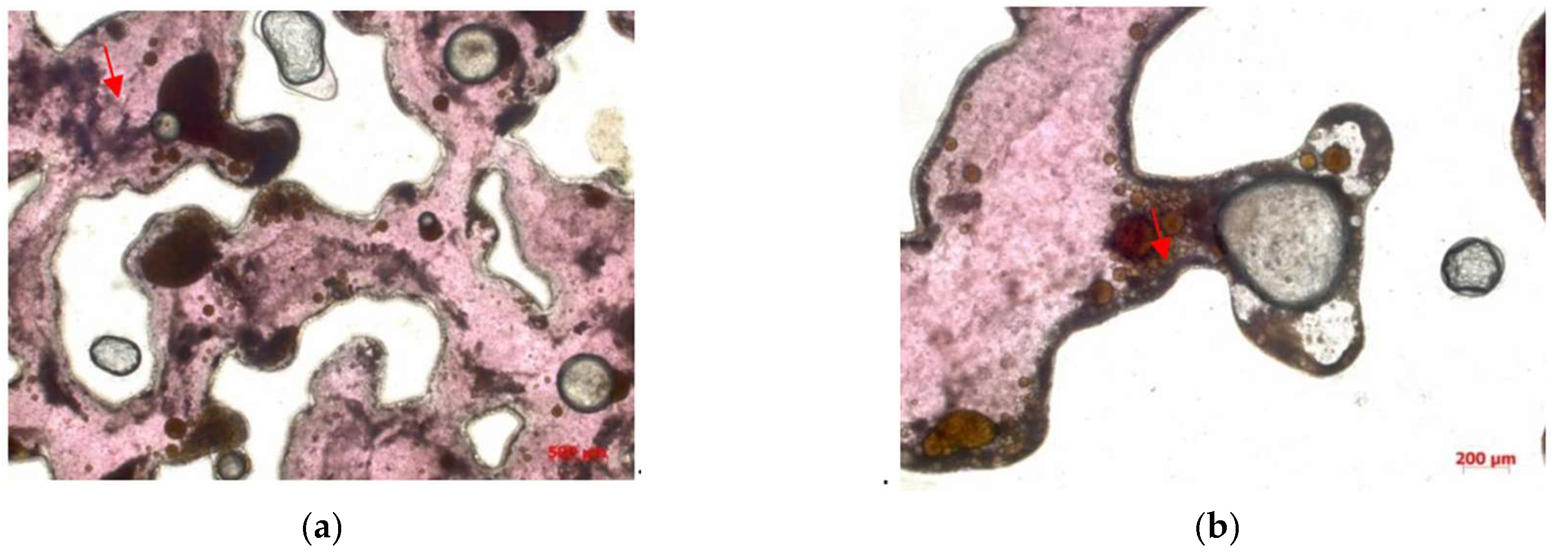
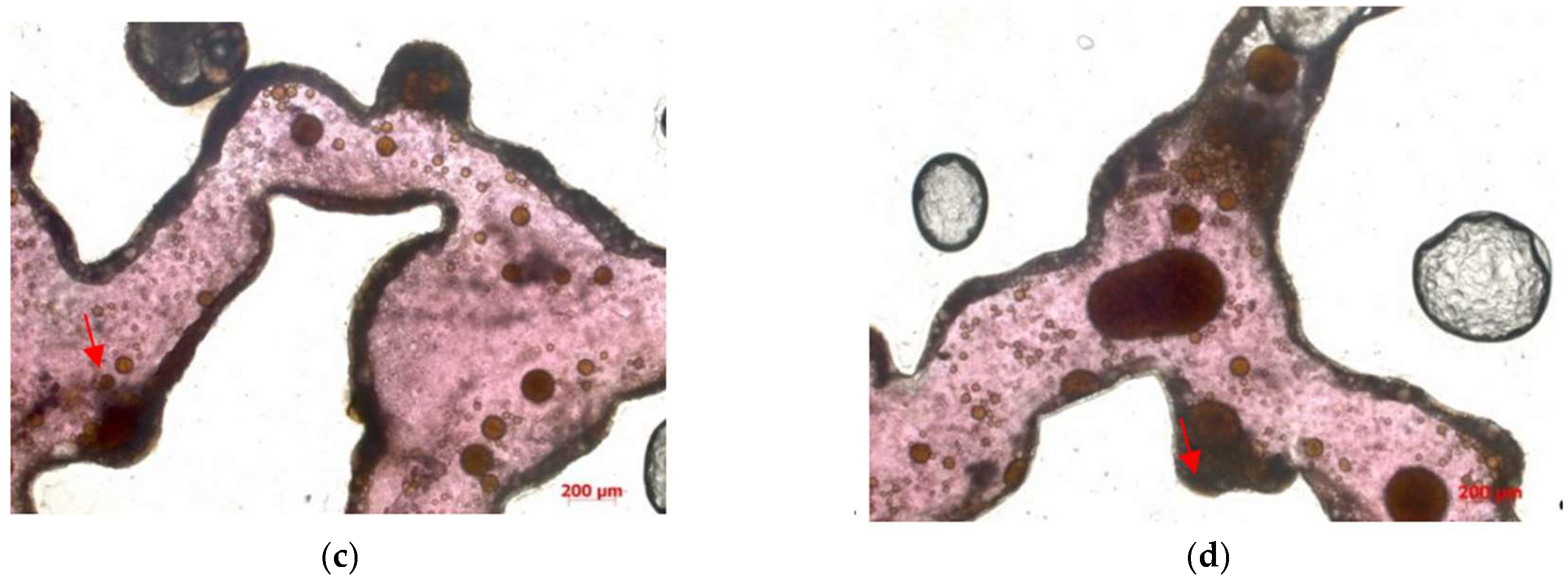
In this experiment, as a micro-scale displacement visualization model is used to simulate the real reservoir, the residual oil types mainly consist of four types: cluster-type, throat-type, pore surface film-type, and corner-type residual oil(see in Figure 13).
6. Conclusion
Particle Migration Phenomenon:During polymer flooding, the polymer acts as a flocculant, causing suspended particles to aggregate. This is due to a combination of effects such as electrostatic neutralization, adsorption bridging, double-layer compression, and network capture. These interactions lead to the movement of suspended particles, which eventually form precipitates that block the throats or get trapped in the pores.
Polymer Flocculation Effects:The flocculation of clay particles in the reservoir leads to migration during polymer flooding. When combined with crude oil, it can form a high-viscosity mixture. This mixture increases the viscosity of the crude oil, making it harder to displace and causing the previously mobile oil to become trapped, especially in the presence of kaolinite flocculation, which blocks the pore throats and reduces oil recovery efficiency.
References and Notes
- Liu, Z.; Bao, J.; Chen, J.; et al. Optimal Strategic Direction for High-Quality Development of Unconventional Oil and Gas. Petroleum Science and Technology Forum 2024, 43, 24–31. [Google Scholar]
- H.k.van Poollen and Associates. Fundamentals of Enhanced Oil Recovery. Tulsa, Oklahoma: Penn Well Books, Division of Penn Well Publishing Company, 1981.
- Mark A K, Carbon Dioxide Flooding Basic Mechanisms and Project Design. International Human Resources Development Corporation, 1984.
- Philip, D.W.; Jon, T.M. Thermal Recovery Methods. Tulsa, Oklahoma: Penn Well Books, Division of Penn Well Publishing Company, 1983.
- Premuzic, E.T.; Clark, J.B. ”Prospects for thermaophilic microorganisms inMEOR”SPE 21015,1991.
- Streeb, L.P. Brown,F G MEOR-Altamon/Blubell field project. SPE 2 4334, 1992. [Google Scholar]
- Cheng Jiecheng. Synthesis of Ultra-High Molecular Weight Polyacrylamide and Its Application Research in Tertiary Oil Recovery[D]. Dalian University of Technology, 2000.
- Deng, J.; Jiang, Y.; Xu, P.; et al. Enhanced Oil Recovery Using Low Salinity Water Flooding Based on Wettability Alteration. Contemporary Chemical Industry 2024, 53, 1351–1356. [Google Scholar] [CrossRef]
- Zhang, X. Application of Fluorescent Analysis in the Study of Residual Oil Distribution After Polymer Flooding Using Freeze-Fracturing. Petroleum Geology and Engineering 2022, 36, 68–71. [Google Scholar]
- Xiang, X.; Jiang, F.; Zhao, X.; et al. Study of Reservoir Damage Factors from Polymer Drilling Fluids. Drilling Fluid & Completion Fluid 1996, 13, 40–41. [Google Scholar]
- Yu, M.; Zhu, W.; Song, H. Development of a Microscopic Visualization Flow Model for Low-Permeability Reservoirs. Journal of Liaoning Technical University (Natural Science Edition) 2013, 32, 1646–1650. [Google Scholar]
- Gao, H.; Sun, W.; Lu, Y.; et al. Experimental Study on Microflow Channel and Displacement Characteristics of Ultra-Low Permeability Sandstone Reservoir: A Case Study of Yanchang Formation, Ordos Basin. Petroleum Geology and Recovery Efficiency 2011, 18, 58–62. [Google Scholar]
- Liu, T.; Xu, H. Simulation of Micro-Residual Oil Distribution in Fan Delta Reservoirs. Journal of China University of Petroleum (Natural Science Edition) 2011, 35, 20–26. [Google Scholar]
- Sirivithayapakorn, S.; Keller, A. Transport of Colloids in Saturated Porous Media: A Pore-Scale Observation of the Size Exclusion Effect and Colloid Acceleration. Water Resources Research 2003, 39, 1–11. [Google Scholar] [CrossRef]
- Li, G.; Ren, W.; Meng, Y.; et al. Micro-Flow Kinetics Research on Water Invasion in Tight Sandstone Reservoirs. Journal of Natural Gas Science & Engineering 2014, 20, 184–191. [Google Scholar]
- Fu, X.; Sun, W. Study of Microscopic Oil-Water Displacement Mechanisms in Low-Permeability Reservoirs: A Case Study of Chang 82 Reservoir in Well Block Zhuang-19, Xifeng Oilfield. Xinjiang Petroleum Geology 2005, 26, 681–683. [Google Scholar]
- Zhu, H.; Zhou, J.; Wan, Y.; et al. Microscopic Mechanism of Gas-Water Flow in Porous Media. Petroleum Geology & Experiment 2004, 26, 571–573. [Google Scholar]
- Li, D.; Zhang, L.; Zhou, K.; et al. Gas-Water Two-Phase Flow Mechanism in Visual Microscopic Pore Models. Journal of China University of Petroleum (Natural Science Edition) 2008, 32, 80–83. [Google Scholar]
- Xie, W.; Zhao, L.; Sun, W.; et al. Flow Unit Division Using a Microscopic Water-Oil Displacement Model for Reservoir Characterisation. Journal of Jilin University 2008, 38, 745–748. [Google Scholar]
- Sun, X.; Suo, L.; Zhang, M.; et al. New Advances in Laser Confocal Scanning Microscopy for Reservoir Analysis in Daqing Exploration Area. Acta Petrologica Sinica 2005, 21, 1479–1488. [Google Scholar]
- Liu, T.; Xu, H. Simulation of Micro-Residual Oil Distribution in Fan Delta Reservoirs. Journal of China University of Petroleum (Natural Science Edition) 2011, 35, 20–26. [Google Scholar]
- Sirivithayapakorn, S.; Keller, A. Transport of Colloids in Saturated Porous Media: A Pore-Scale Observation of the Size Exclusion Effect and Colloid Acceleration. Water Resources Research 2003, 39, 1–11. [Google Scholar] [CrossRef]
- Song, J. Synthesis of Hyperbranched Polyacrylamide and Its Flocculation Performance. Chemical Engineering Design Communications 2019, 45, 108–109. [Google Scholar]
- Chen, W. Quantitative Distribution and Potential Recovery Study of Micro-Residual Oil After Strong Water Flooding in Oil Layers. Marine Petroleum 2017, 37, 47–52. [Google Scholar]
- Wu, H. Effects and Mechanisms of Leaching Agent Anions on the Exchange and Diffusion of La3+ and Al3+ at Kaolinite Interfaces. Jiangxi University of Science and Technology 2022.
- Tu, R. Synthesis and Flocculation Performance of Hyperbranched Polyacrylamide. Shaanxi University of Science and Technology 2018. [Google Scholar]
- Chen, W. Quantitative Distribution and Potential Recovery Study of Micro-Residual Oil After Strong Water Flooding in Oil Layers. Marine Petroleum 2017, 37, 47–52. [Google Scholar]
Figure 1.
Inter-particle adsorption of residual oil diagram.
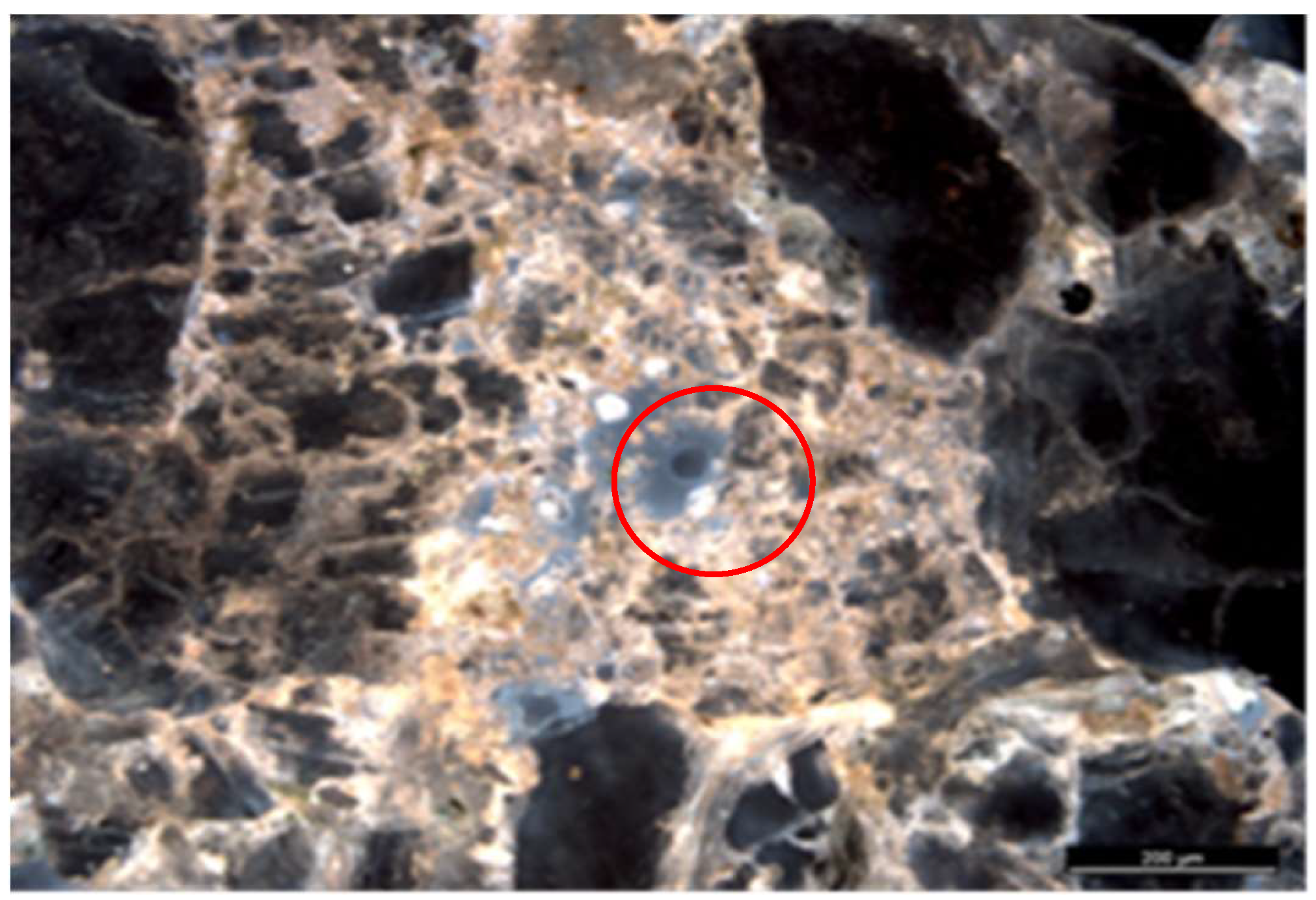
Figure 2.
Inter-particle adsorption of residual oil (a) CT 3D image; (b) Fluorescence photograph.
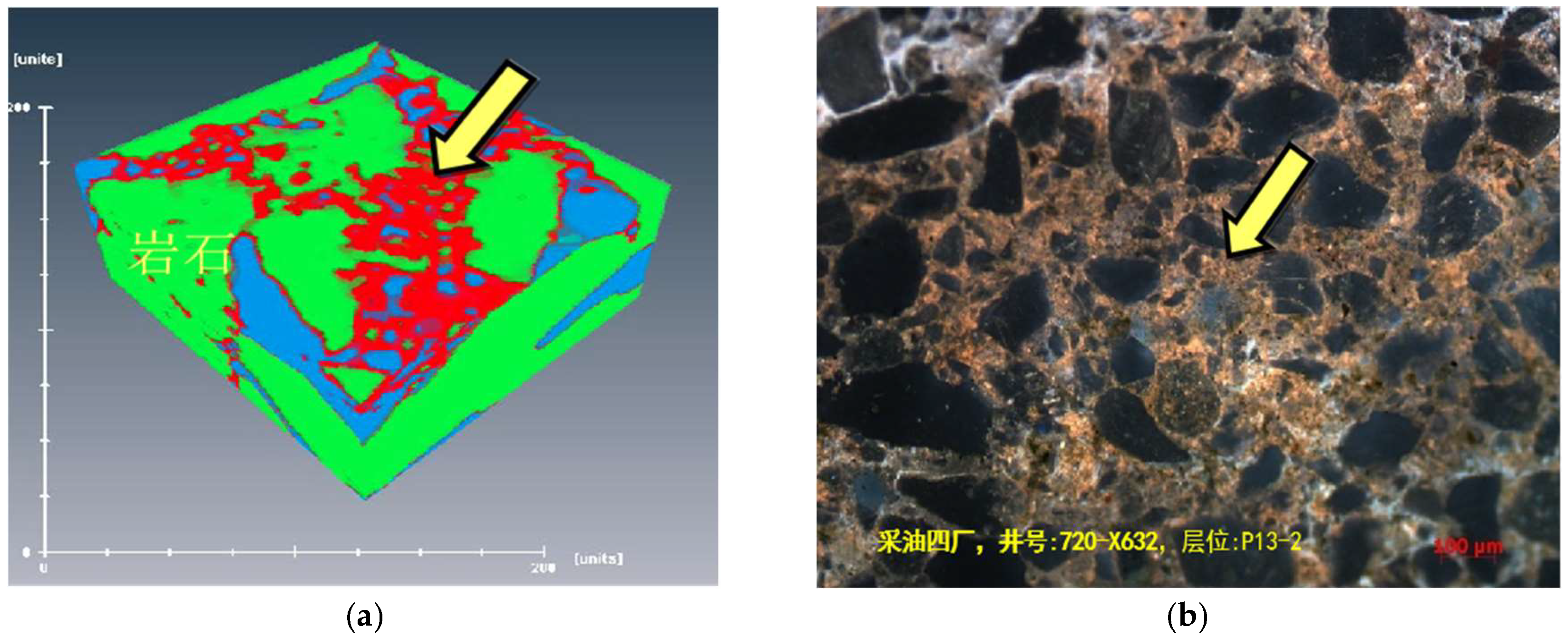
Figure 3.
Flocculation diagram (a) Kaolinite water suspension;(b) Formation of flocs; (c) Precipitation.
Figure 3.
Flocculation diagram (a) Kaolinite water suspension;(b) Formation of flocs; (c) Precipitation.
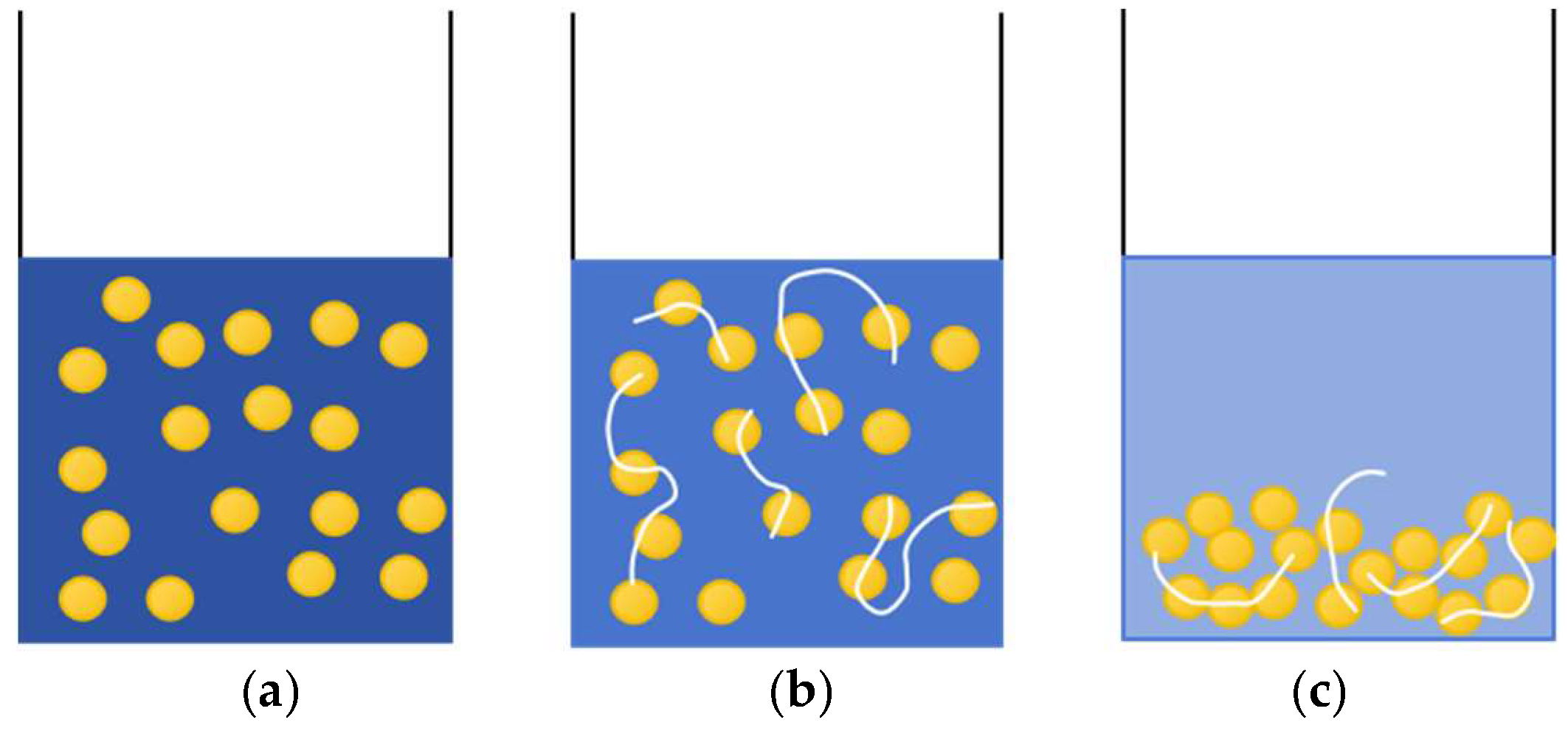
Figure 4.
Experimental apparatus diagram 1 Micro-injection pump; 2 Injection syringe; 3 Microscope; 4 Valve;5 Micro-visualization model holder; 6 Micro-visualization model; 7 Heating plate; 8 Parallel light source;9 Liquid recovery collection container; 10 Image acquisition computer.
Figure 4.
Experimental apparatus diagram 1 Micro-injection pump; 2 Injection syringe; 3 Microscope; 4 Valve;5 Micro-visualization model holder; 6 Micro-visualization model; 7 Heating plate; 8 Parallel light source;9 Liquid recovery collection container; 10 Image acquisition computer.
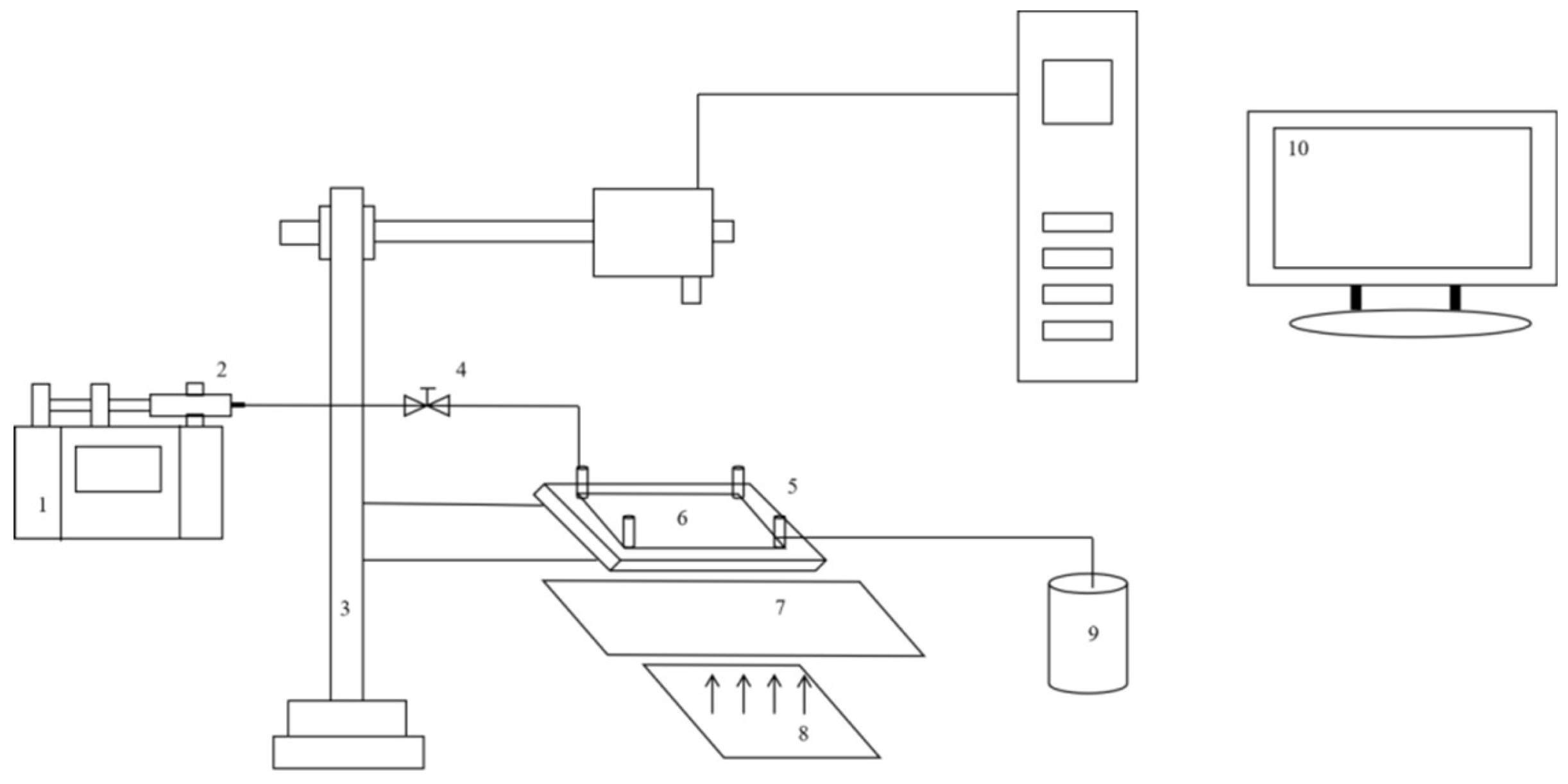
Figure 5.
Cast thin sheet (a) laser confocal scanning injection thin sheet; (b) vectorised image after vectorisation by software.
Figure 5.
Cast thin sheet (a) laser confocal scanning injection thin sheet; (b) vectorised image after vectorisation by software.
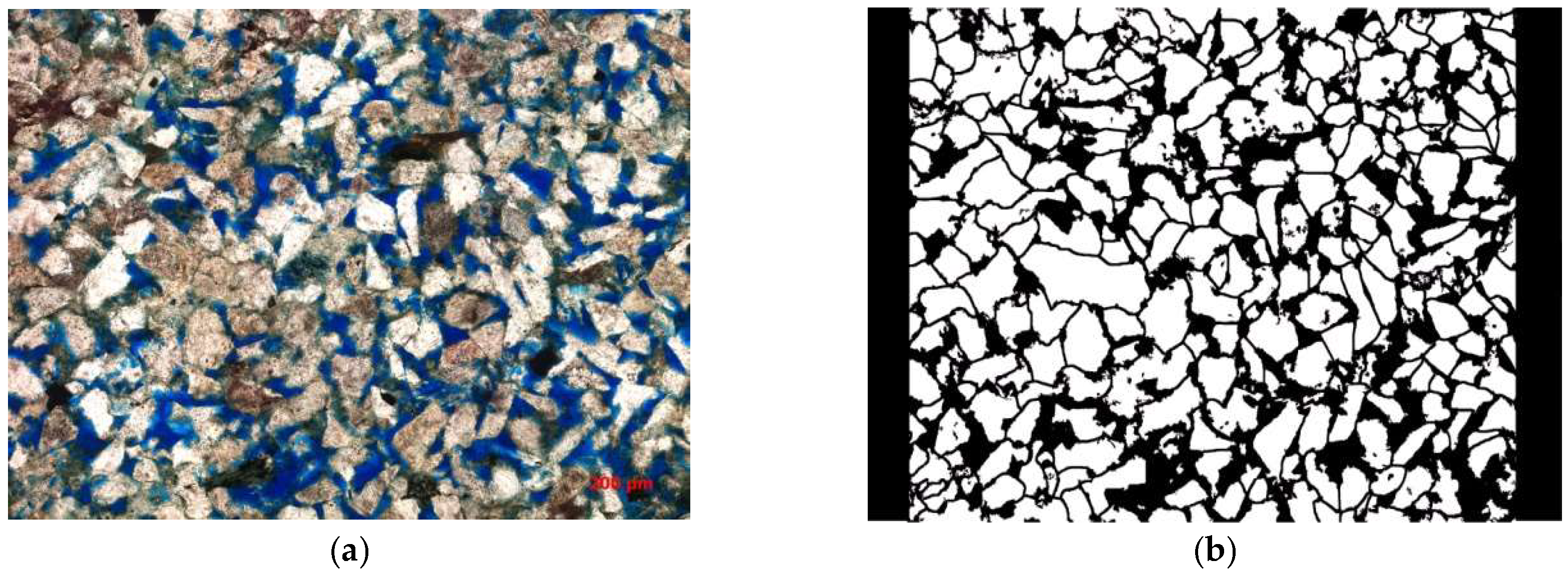
Figure 6.
Microscopic displacement etching model.
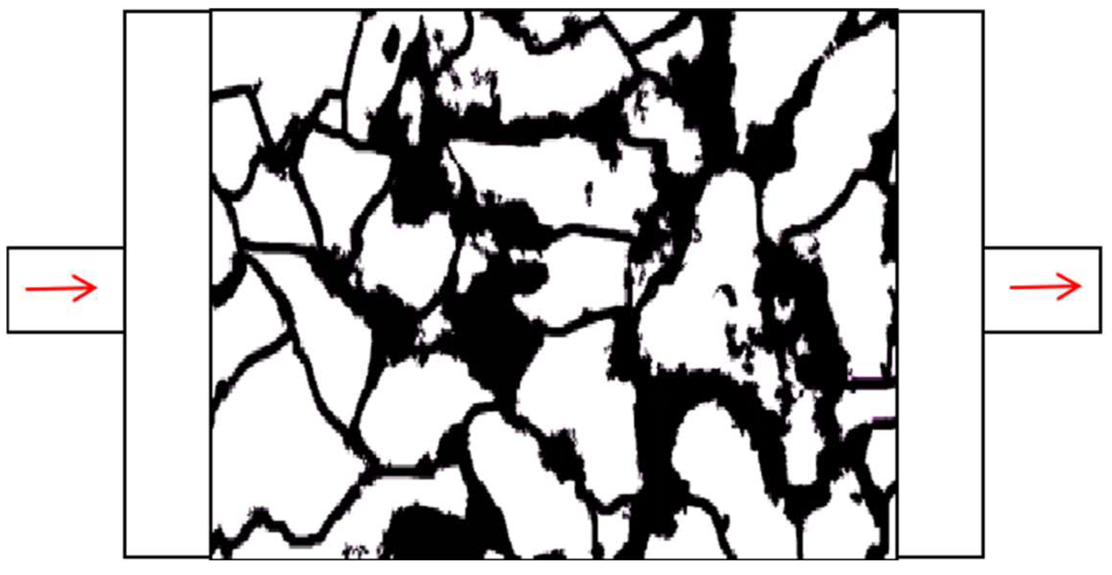
Figure 7.
Kaolinite aqueous suspension (30% concentration), transmitted light photograph, temperature 46°C.
Figure 7.
Kaolinite aqueous suspension (30% concentration), transmitted light photograph, temperature 46°C.
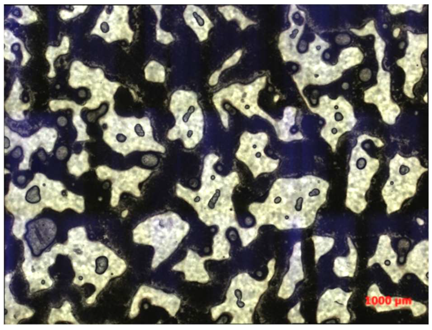
Figure 8.
The oil displacement effect images from Experiment 1 are as follows (a) Waterflooding (10 PV) transmitted light photograph; (b) Binary composite flooding (10 PV) transmitted light photograph; (c) Waterflooding (20 PV) transmitted light photograph; (d) Binary composite flooding (20 PV) transmitted light photograph.
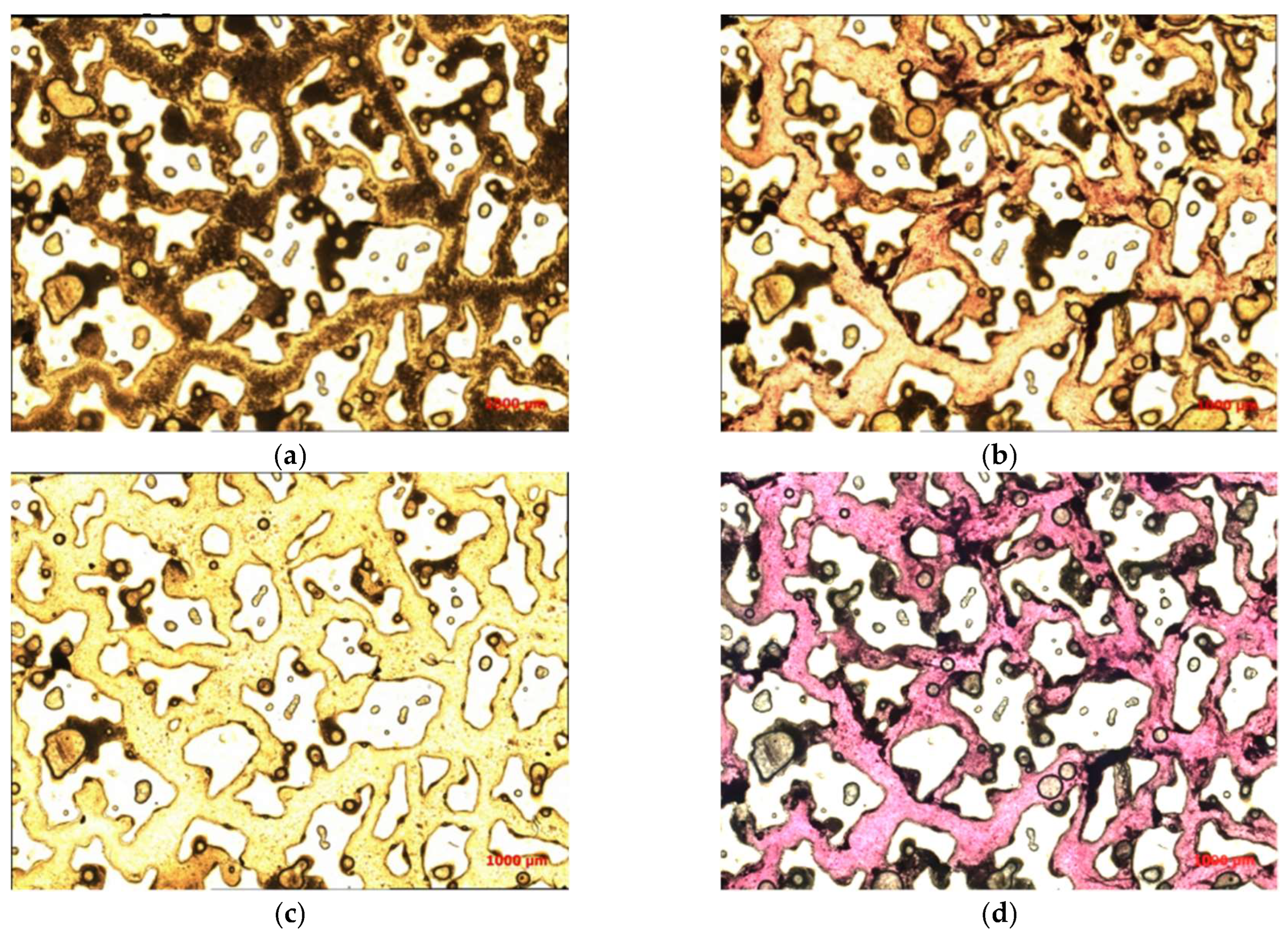
Figure 9.
The oil displacement effect images from Experiment 2 are as follows (a) Binary composite flooding (10 PV) displacement effect; (b) Binary composite flooding (20 PV) displacement effect; (c) Binary composite flooding (80 PV) displacement effect.
Figure 9.
The oil displacement effect images from Experiment 2 are as follows (a) Binary composite flooding (10 PV) displacement effect; (b) Binary composite flooding (20 PV) displacement effect; (c) Binary composite flooding (80 PV) displacement effect.
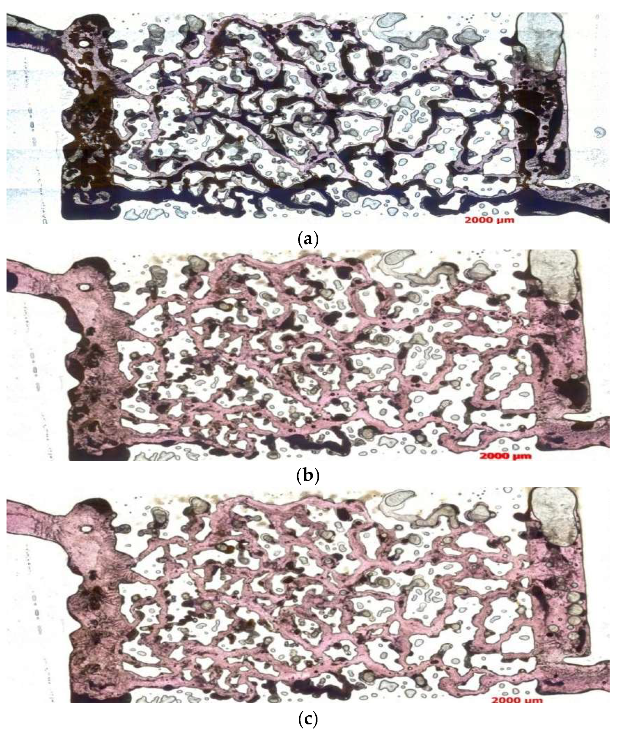
Figure 10.
The oil displacement effect images from Experiment 3 are as follows (a) Binary composite flooding (10 PV) displacement effect; (b) Binary composite flooding (20 PV) displacement effect; (c) Binary composite flooding (80 PV) displacement effect.
Figure 10.
The oil displacement effect images from Experiment 3 are as follows (a) Binary composite flooding (10 PV) displacement effect; (b) Binary composite flooding (20 PV) displacement effect; (c) Binary composite flooding (80 PV) displacement effect.

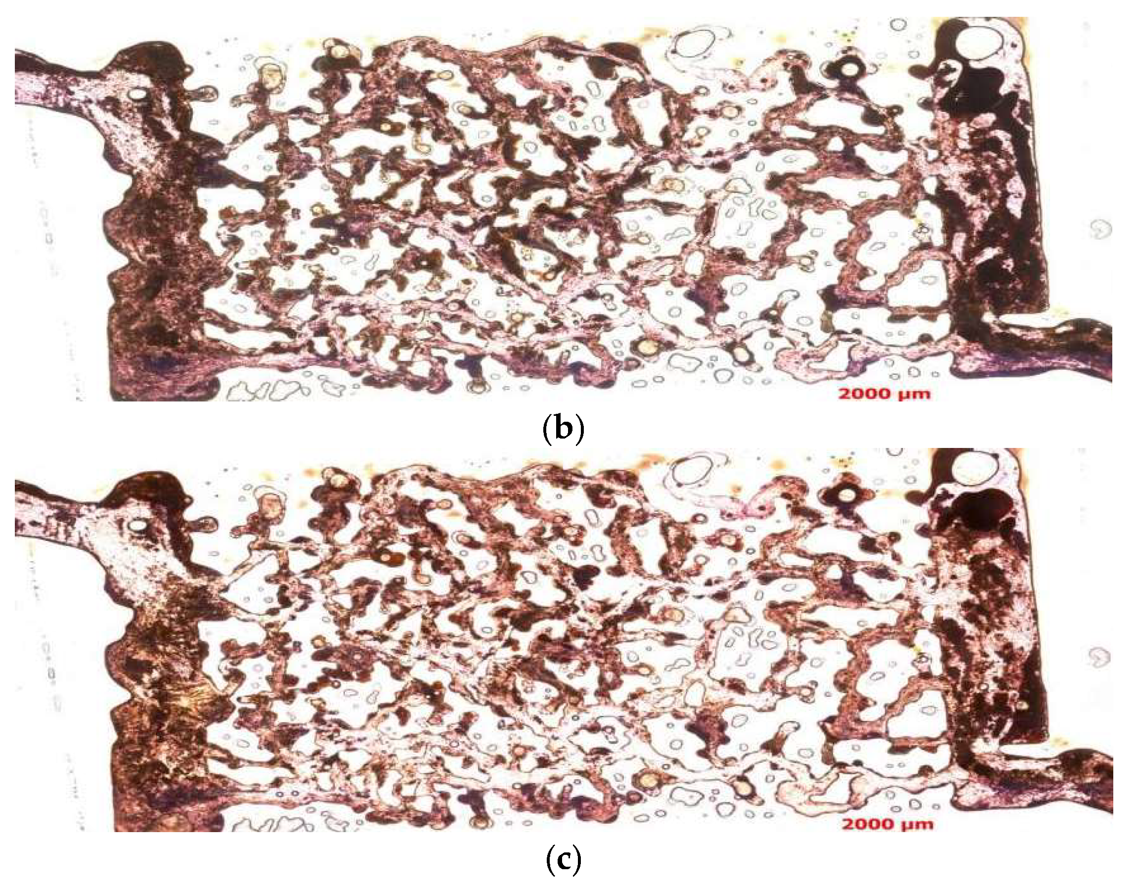
Figure 11.
The distribution of the mixed solution is shown as follows (a) Transmitted light photograph; (b) Orthogonal light photograph.
Figure 11.
The distribution of the mixed solution is shown as follows (a) Transmitted light photograph; (b) Orthogonal light photograph.
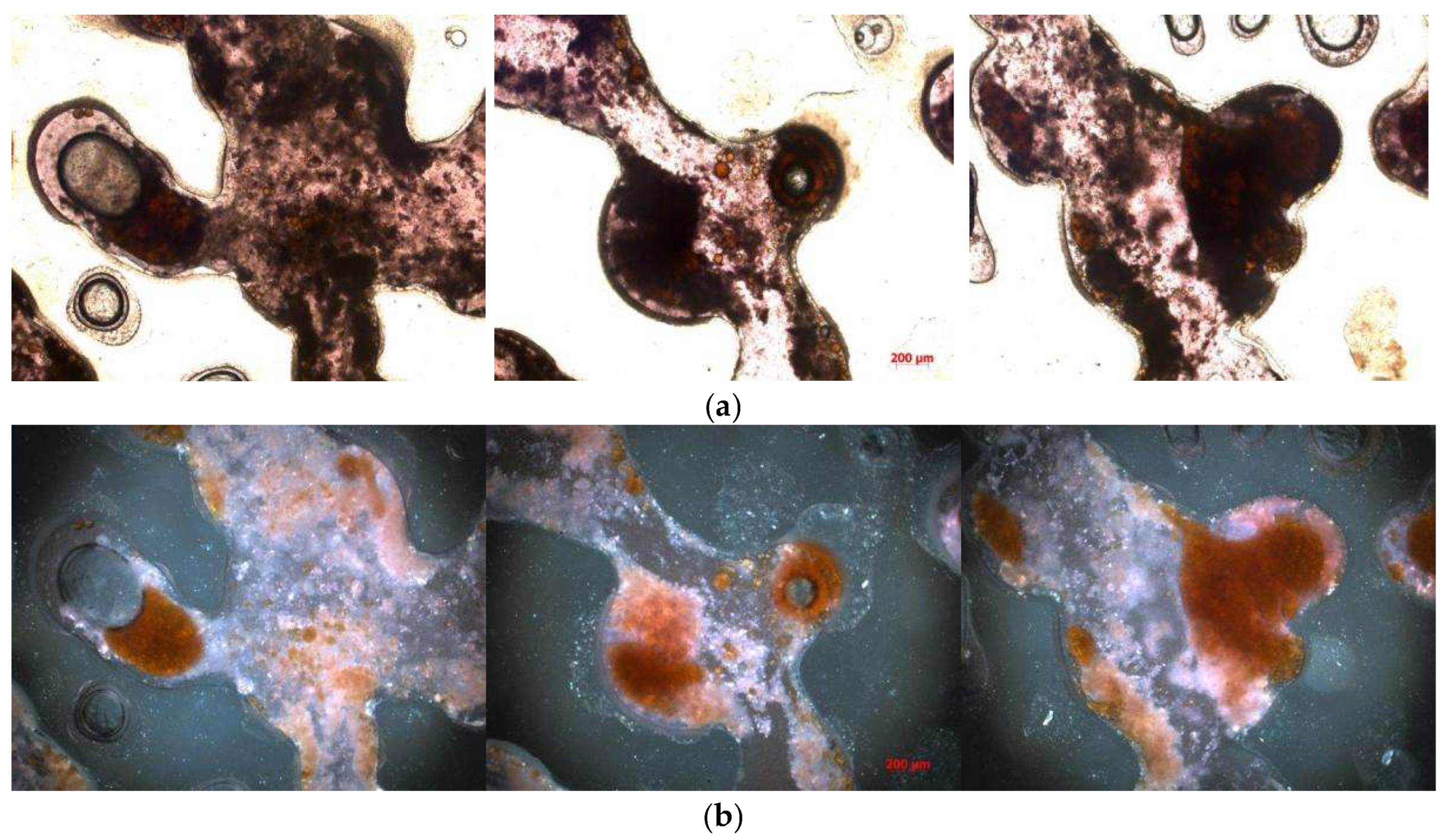
Figure 12.
The schematic of residual oil distribution types is as follows 1 Pore surface film-type 2 Grain adsorption-type 3 Corner-type 4 Throat-type 5 Cluster-type 6 Intergranular adsorption-type.
Figure 12.
The schematic of residual oil distribution types is as follows 1 Pore surface film-type 2 Grain adsorption-type 3 Corner-type 4 Throat-type 5 Cluster-type 6 Intergranular adsorption-type.
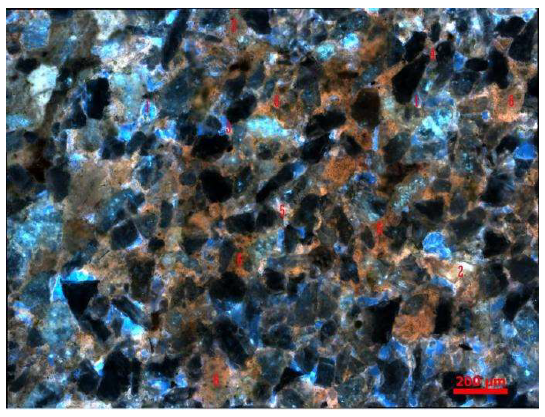
Figure 13.
The residual oil distribution types are as follows (a) Cluster-type; (b) Throat-type; (c) Pore surface film-type; (d) Corner-type.
Figure 13.
The residual oil distribution types are as follows (a) Cluster-type; (b) Throat-type; (c) Pore surface film-type; (d) Corner-type.
Disclaimer/Publisher’s Note: The statements, opinions and data contained in all publications are solely those of the individual author(s) and contributor(s) and not of MDPI and/or the editor(s). MDPI and/or the editor(s) disclaim responsibility for any injury to people or property resulting from any ideas, methods, instructions or products referred to in the content. |
© 2024 by the authors. Licensee MDPI, Basel, Switzerland. This article is an open access article distributed under the terms and conditions of the Creative Commons Attribution (CC BY) license (http://creativecommons.org/licenses/by/4.0/).
Copyright: This open access article is published under a Creative Commons CC BY 4.0 license, which permit the free download, distribution, and reuse, provided that the author and preprint are cited in any reuse.


