Submitted:
22 November 2024
Posted:
22 November 2024
You are already at the latest version
Abstract
Background/Objectives: The subject of this work is the reconstruction of the inner mechanics of Götz von Berlichingen's second "Iron Hand". The complex inner mechanics were unknown until Christian von Mechel published a detailed description in 1815. In this artificial hand, each finger can be engaged individually in its three joints and the thumb in one joint. Methods: Based on this description, the individual components were reconstructed at an enlarged scale of 2:1 using CAD software and a 3D printer for the mechanisms. In addition, an FEM analysis was carried out for the components exposed to the greatest stress in order to identify critical areas. Results: By making some adjustments to the mechanics, it was possible to reproduce the mechanisms on a scale of 2:1 on the basis of the index finger. However, if the model was scaled back to 1:1, the internal plastic components were too fragile. This problem was caused by the properties of the 3D printing materials and could be solved by manufacturing the springs from steel. Conclusions: This work aims to make a valuable contribution to the preservation and understanding of the historical artificial second "Iron Hand" of Götz von Berlichingen. It once again demonstrates the very precise and detailed craftsmanship of goldsmiths of that time.
Keywords:
Iron Hand
; Götz von Berlichingen
; 3D computer-aided design
; 3D multi-material polymer printing
; finite element method
; hand prosthesis
1. Introduction
In the last few years, several three-dimensional computer-aided design (3D-CAD) reconstructions of the first “Iron Hand” of the famous Franconian Imperial Knight, Götz von Berlichingen (1480–1562), have been presented [1,2,3,4,5,6,7]. Götz von Berlichingen lost his right hand due to a cannon ball splinter injury in 1504 in the War of the Succession of Landshut [8]. With the hand prosthesis developed in response to this injury, the artificial thumb and two finger blocks could be moved by a spring mechanism in their basic joints and released by a push button.
A second “Iron Hand” was developed some years later, in which the fingers could be passively moved in all joints. In 1815, the Basel-born copper engraver Christian von Mechel (1737–1817) illustrated and described the second “Iron Hand” and its sophisticated mechanics in a short book of 10 pages, containing two useful aquatint etchings of the hand prosthesis at a scale of 1:1 [8,9] (see Appendix A, Figure A1, Figure A2 and Figure A3). Mechel was given permission by the von Berlichingen family to dismantle the hand for this purpose. Recently, we published our first draft 3D-CAD reconstruction of the finger mechanics of the second “Iron Hand” based on the Mechel drawings [10]. However, upon printing the parts with a high-end multi-material polymer printer, the levers and springs of the finger mechanism broke after only a few movements. Furthermore, the Mechel publication did not explain every detail of the hand and is not quite 1:1 in scale, as a result of which the components were not correctly matched.
Therefore, the aim of this piece was to analyze the mechanics of the second "Iron Hand" more deeply. Using finite element method (FEM) analysis, particular attention was paid to the critical components that are exposed to the greatest stresses in order to ensure a functional and realistic replica. As the mechanisms are similar in terms of all fingers (with the exception of the thumb), and in order not to increase the complexity of the model unnecessarily, the index finger was chosen for the replica. Thus, as a first step, the mechanisms were reconstructed at an enlarged scale of 2:1. To verify the model, the reconstruction was 3D-printed and analyzed regarding its functionality and robustness. This 3D-printed model should not only demonstrate the historical accuracy of the mechanisms, but also serve as a functional model that illustrates the complex mechanics in practice. Several challenges that have arisen during the reconstruction are explained and possible solutions are proposed. For example, manufacturing techniques and materials had to be found for the sensitive parts of the mechanisms. It was also necessary to make some changes to the parts themselves in order to achieve functioning mechanisms. In particular, the manufacturing of the springs from steel is outlined to ensure the functionality and longevity of the prosthesis.
2. Materials and Methods
2.1. Preparation and Planning
The drawings by Christian von Mechel served as the basis for the reconstruction [8]. To simplify the illustration, Mechel only indicated some of the internal components in various figures, but this is not immediately obvious and initially causes confusion, as some of the drawings are imprecise and not every component is shown from every side. For this reason, a 2D drawing was first made of the index finger at a scale of 1:1. In order to determine all of the required dimensions, von Mechel´s drawings were loaded into a drawing program, resized to the original size based on a few given dimensions, and used as a template to create digital copies of the drawings. Afterwards, this sketch served for any relevant dimension needed for reconstruction (Figure 1).
As the interior parts are far too small and prone to breakage for the intended 3D-printing materials, the model was initially reconstructed at an enlarged scale of 2:1.
2.2. Reconstruction in Autodesk Inventor
The reconstruction of the second “Iron Hand” is based on the drawings by Christian von Mechel using the CAD software Autodesk Inventor (Autodesk Inc., Dublin, Ireland). Measurements were taken from von Mechel's publication and the components were reconstructed as accurately as possible at a scale of 2:1. However, some adjustments were made. For example, the shape of the corpus was changed in order to simplify it.
2.3. Manufacturing the First Prototype of the Reconstructed Model
The first prototype was printed by using two different materials: PETG (polyethylene terephthalate glycol-modified) and PLA (polylactic acid). To print mechanical components, PETG should be selected. Compared to PLA, it has higher temperature resistance, is tougher, and therefore less fragile. In addition, the thermal expansion of PETG is low, which means that the material adheres well to the build plate and does not deform [12].
Nevertheless, the spring integrated into the phalanx (cf. “c d e” in Figure A3, Appendix A) was printed from both materials for testing, which confirmed the above. The spring made of PETG can withstand light pressure, whereas the spring made of PLA broke directly at the arch. It was therefore decided to print all parts with PETG.
As it was not possible to print the rods and bolts with the 3D printer, these parts were realized with threaded rods made of steel with a galvanized surface and diameters of 4 and 6 mm, respectively.
2.4. Adjustments to the CAD After the First Test Print
After the first prints, it became apparent that the springs in the phalanges had to be designed very precisely. Therefore, the length as well as the shape of the spring were altered. Several versions were printed and tested to see which fitted best. It is important that the spring exerts enough pressure through the arc to push up the locking lever (cf. “f g” in Figure A3, Appendix A). However, too much pressure must not be exerted, as the spring would then need too much space to expand and would hit the inner wall, causing the mechanisms to jam. For example, the size and height of the bow were changed. Figure 2 shows several versions.
2.5. Finite Element Method (FEM)
To reconstruct the most mechanically stressed parts to withstand the stress of typical usage, the development was supported by FEM analysis for the spring (cf. “c d e” in Figure A3, Appendix A) and the locking lever (cf. “f g” in Figure A3, Appendix A) of the medial phalanx (cf. “B” in Figure A3, Appendix A), as the greatest deformation or even failure is suspected for these components. The FEM analysis was carried out using Autodesk Inventor software.
The external forces were set for the following case: The phalanges were in a bent position and the lever on the hook (cf. “f” in Figure A3, Appendix A) is then pushed down to return to the extended position. In this case, the greatest external force is exerted on both components. At the upper end of the spring (cf. “c” in Figure A3, Appendix A), a force is applied downwards by the locking lever, causing the spring to expand downwards. Due to the preload of the spring, the wall of the phalanx presses on the spring from below. Additionally, the spring in the proximal phalanx presses into the spring’s hole (cf. “d” in Figure A3, Appendix A) from behind and the spring (cf. “c d e” in Figure A3, Appendix A) from the distal phalanx applies some force to the nose of the spring (cf. “e” in Figure A3, Appendix A).
A similar analysis was carried out for the locking lever (cf. “f g” in Figure A3, Appendix A): The force exerted by the spring from below, the force exerted on the lever when the hook (cf. “f” in Figure A3, Appendix A) is pressed down, and the forces on the side (cf. “g” in Figure A3, Appendix A) exerted on the lever by the teeth of the joint to the next phalanx (cf. “A” in Figure A3, Appendix A) (see arrows in Figure 10) were defined. For this FEM analysis, the same values for yield strength and tensile strength were applied in the analysis as for the spring.
3. Results
3.1. Presentation of the Reconstructed Second “Iron Hand”
Figure 3 and Figure 4 show the reconstructed model of the index finger of the second “Iron Hand” of Götz von Berlichingen as a technical drawing and the printed model at an enlarged scale of 2:1, respectively.
The dimensions of the components were correct in each case, but the function could not be guaranteed in the complete replica. If only the proximal phalanx is assembled with the medial phalanx, the spring of the medial phalanx can exert the necessary force to bring the engaged distal phalanx back into the starting position (stretched position) (cf. phalanges “A”, “B”, and “C” in Figure A3, Appendix A). However, as soon as the proximal phalanx is attached and the spring of this phalanx presses on the spring of the medial phalanx, the mechanism starts blocking. This is probably due to the excessive pressure exerted on the spring of the medial phalanx from the proximal phalanx, which means that it can no longer expand sufficiently, and the mechanism is blocked. Applying more force by thickening the spring did not solve this problem, as the spring became too rigid. This indicates that PETG is not a suitable material for the spring.
In addition, the spring in the hand corpus (cf. “n” in Figure A3, Appendix A) does not function as desired. It does not remain in the intended notch and does not exert any pressure on the tension hook for the proximal phalanx (cf. “l m” in Figure A3, Appendix A), such that the return mechanism did not work properly. In addition, the proximal phalanx cannot be engaged to remain in the flexion position, since the locking lever in the corpus does not remain in the desired position. This would have to be pressed down in order to exert pressure against the teeth and ensure the latching mechanism works.
3.2. Experimental Optimization Approach of the Model
To optimize the challenges outlined in Chapter 3.1., some changes to the model were made.
Firstly, the spring in the hand corpus (cf. “n” in Figure A3, Appendix A) was firmly connected to the tensioning hook (cf. “l m” in Figure A3, Appendix A). In addition, the shape of this tensioning hook was modified (Figure 5) according to the shape of the springs (cf. “c d e” in Figure A3, Appendix A) in the phalanges. It was intended to enable the tensioning hook to apply enough force on the proximal phalanx to move it from the flexion position to the extension position. The original tensioning hook (cf. “l m” in Figure A3, Appendix A) was too tight and did not flex enough when the proximal phalanx was flexed. However, this may be due to a transposition error in the drawing or to the scaling at an enlarged scale of 2:1. It is assumed that the hook can be shaped and flexed better at a scale of 1:1.
The proximal and medial phalanges were closed on the side through which the spring of the next phalanx passes. A small opening was added to imitate the hole in the spring (cf. “d” and “c d e”, respectively, in Figure A3, Appendix A). This design means that no pressure is exerted on the springs (cf. “c d e” in Figure A3, Appendix A) by the following phalanx, which may improve the chain reaction mechanism of the finger. As soon as the locking lever of the proximal phalanx is pressed down on the hook (cf. “f” in Figure A3, Appendix A), the medial phalanx snaps back into the extended position. If the proximal phalanx presses down the hook (cf. “f” in Figure A3, Appendix A) of the locking lever of the medial phalanx, the proximal phalanx also snaps back to its original position.
3.3. Results of the FEM Analysis
Figure 9 shows the results of the FEM analysis for the spring. The grid structure visualizes the initial position of the spring, while the deformation of the spring is shown in color. The color scale shows the distribution of the von Mises stress in the component, with blue indicating low stresses and with red indicating high stresses. The stresses range from 0 MPa to 72.81 MPa, with the maximum stress value occurring at a specific point in the component. In Autodesk Inventor, the tensile strength and yield strength of the material used can be displayed, both of which are approximately 55 MPa for PETG. These values are decisive for assessing the material’s strength. In this FEM analysis, there are areas where the von Mises stress exceeds the yield strength of 55 MPa. This means that these areas are susceptible to nonreversible deformation. This is the case at the orange and red areas on the small nose of the spring (small left stick in Figure 9). The results of the FEM analysis are verified by the 3D-printed model.
The results of the FEM analysis of the locking lever (cf. “f g” in Figure A3, Appendix A) are shown in Figure 10. The maximum stress value for the locking lever is 16.36 MPa. Thus, there are no areas in which the von Mises stress exceeds the yield strength of 55 MPa. This means that the component should not suffer any nonreversible deformation under the given load conditions. The maximum von Mises stress is well below the yield strength and tensile strength of the material, indicating that the component is safe and reliable.
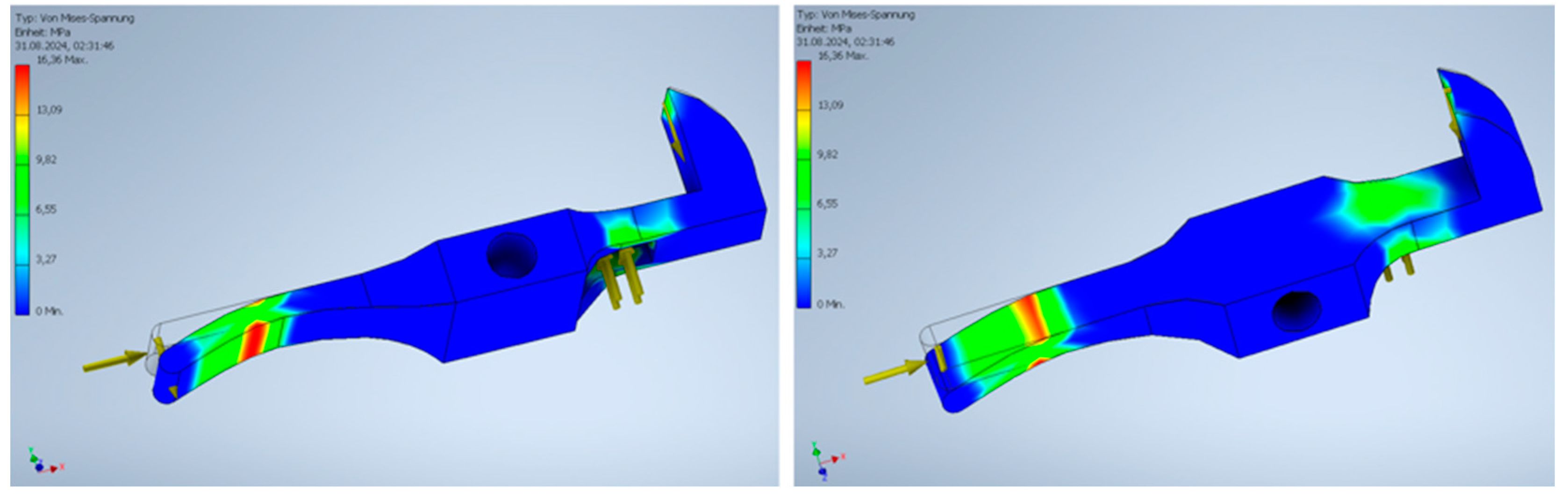
Figure 10.
FEM analysis of the locking lever (cf. “f g” in Figure A3, Appendix A).
Figure 10.
FEM analysis of the locking lever (cf. “f g” in Figure A3, Appendix A).
The results of the analysis of the locking lever were also confirmed by the 3D-printed model. Even after several actuations of the mechanisms and the associated loads, the lever did not bend. According to the analysis, the yield strength of the von Mises stresses was not exceeded here.
3.4. Material Analysis of the Spring
As the 3D-printed springs made of PETG sometimes broke after several loads, springs with different steel thicknesses were tested for comparison. Additionally, this was also performed to imitate the steel spring in the original Götz prosthesis.
In the first test, an existing carbon steel with a thickness of 1.8 mm was used. While forming the 1.8 mm thick steel, it was realized that it was not suitable for use as a spring, as it was far too unruly. Two thinner steel sheets were therefore procured, which were 1.2 mm and 0.75 mm thick. These two springs were also heated and then forged with a hammer (see Figure 11). The spring made from the 1.2 mm wide steel was similar to the 1.8 mm string, too stiff, whereas the 0.75 mm wide spring mimicked the function of a spring very well. As soon as some pressure was applied from above, it expanded slightly in width and returned to its original shape as soon as it was released. Figure 12 presents the three results.
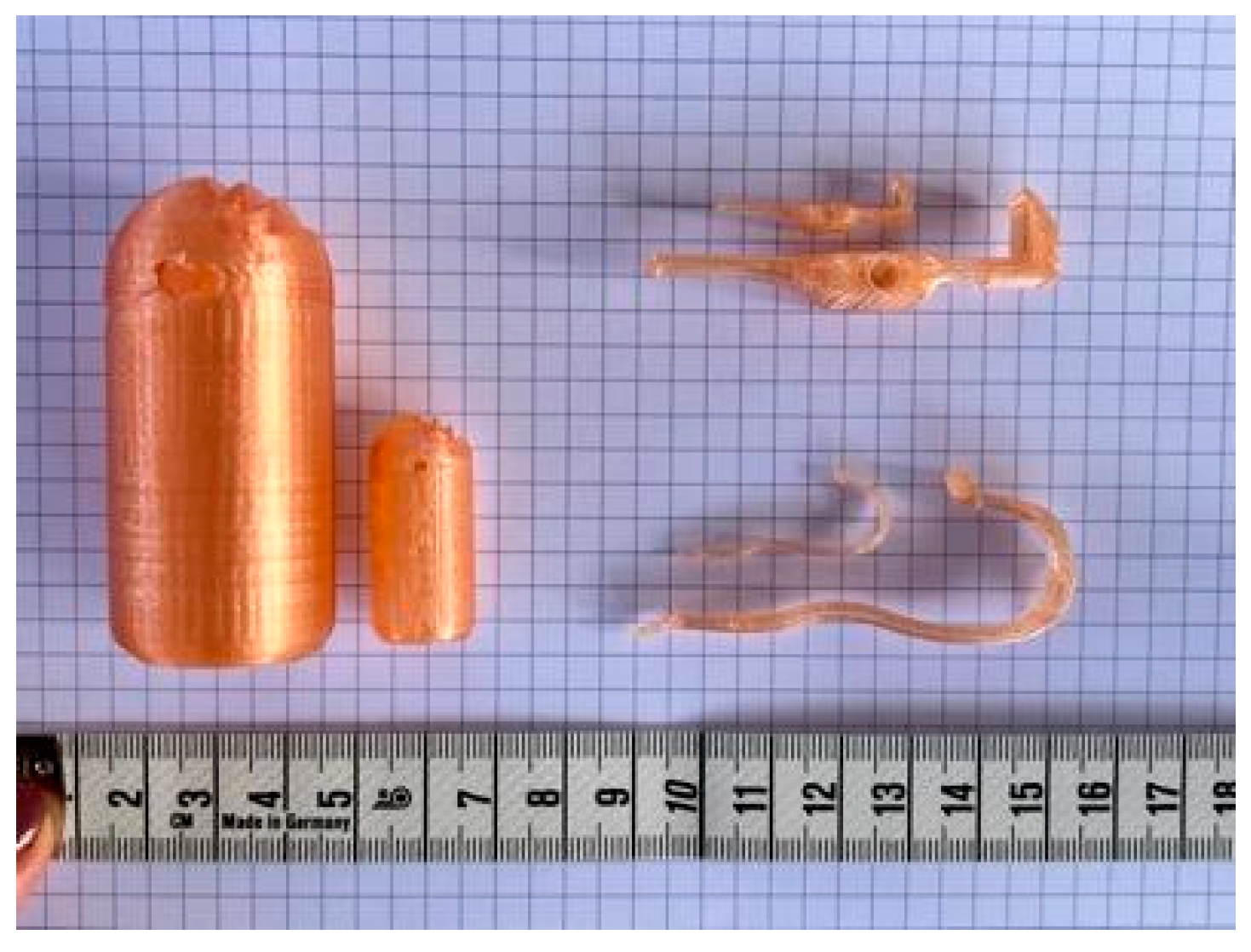
3.5. Downscaling to a Scale of 1:1
Finally, the distal phalanx, the spring, and the locking lever of the medial phalanx were scaled to a scale of 1:1. Figure 13 shows a comparison between the 2:1 and 1:1 scales. In the 1:1 scale, the outer wall of the phalanx is 1 mm thick, as is probably also the case with the original second “Iron Hand”. Despite the scaling, the link is very stable and could function as such. The inner mechanical parts, however, are very unstable at this scale. Although the spring can withstand light pressure and returns to its original shape, it is too weak. The locking lever also appears stable at first glance, but will probably also break after applying force several times. This means that the 3D-printed reconstruction works at a scale of 2:1, but unfortunately, it is not possible to create a reliable model at a scale of 1:1 by using 3D printing.
In order to obtain a stable and reliable model at a scale of 1:1, other materials must be used.
4. Discussion
As shown, the springs (cf. “c d e” in Figure A3, Appendix A) are the weakest parts in our 3D-printed model of the hand prosthesis. The restoring force is insufficient, leading to a nonreversible deformation. This weak point is probably only due to the choice of PETG material, as PETG is a soft material with a low elastic limit. With the original “Iron Hand”, both challenges with the spring probably do not occur so quickly, as the E-modulus of the steel has a higher elastic limit and the restoring force of the spring is higher due to the higher stiffness of steel compared to PETG.
In addition, the printing direction and other printing parameters, such as filament thickness, working temperature, and printing speed, play an important role in filament-based printing processes. These parameters have a significant impact on the stability of the printed part. At this point, it is important to note that the conducted FEM analyses considered the analyzed part as a solid body consisting completely of the filament material. Due to the printing paths, however, this boundary condition is not fulfilled, which means that deviations from the results of the FEM analysis are likely.
The gearing is another weakness in the design. The specification of the possible finger positions could only be speculated about on the basis of Christian von Mechel's drawings. Exact specifications for the flexion, in degrees, as well as the number of “engagement positions” are missing in the original draft and were assumed for this reconstruction. By changing the angles in the teeth, especially for the proximal phalanx, the mechanism of the locking lever (cf. “i k” in Figure A3, Appendix A) could be improved reliably. Optimizing the toothing could also make it easier to release the locking mechanism, which would allow the “chain reaction” to function reliably.
In general, it should be borne in mind that the prosthesis in its original size, both in steel and as a 3D-printed replica, is an extremely delicate construction. Due to the original size, all bolts, wall thicknesses, etc., would be smaller, making the component more unstable. As a result, the prosthesis is subject to a high degree of wear and cannot be used for every type of work. The “Iron Hand” also does not have a strong grip due to the delicate spring-lever mechanism, which also limited the use of the hand prosthesis.
This confirms the historical tradition that, in contrast to the first “Iron Hand”, the second “Iron Hand” of Götz von Berlichingen only served as a “Sunday” hand [3]. According to tradition, the second “Iron Hand” shows hardly any signs of wear as opposed to the first “Iron Hand” [14]. The system with the locking mechanism could not be used for sword fights or similar work, because, as already mentioned, the grip strength of the prosthesis was not sufficient and the resulting mechanical damage from a direct impact as well as impacts that the sword shaft would exert on the phalanges of the fingers while holding the sword would have been significant. Due to the complexity of the components, maintenance of the prosthesis was very time-consuming and could only be carried out by qualified personnel [11].
5. Conclusions
It is impressive that such a mechanically sophisticated prosthesis could be created with the limited technical possibilities of that time compared to today's technologies. It must have required a high degree of craftsmanship, undoubtedly ahead of its time. The prosthesis itself represents a milestone in the history of hand prosthesis development. The replication of the second “Iron Hand” made of PETG was a success in terms of the functioning of the internal mechanics and a possible step towards the development of low-cost hand prostheses made of plastic material. However, the high level of wear and the instabilities of the material, especially for the springs, requires optimization.
As an outlook for future research, a reconstruction with metal parts appears promising. Today, even the metalworking of complex elements is simplified by the use of computerized numerical control (CNC) milling machines, often with a direct computer access module (CAM) interface.
Supplementary Materials
The following supporting information can be downloaded at: www.mdpi.com/xxx/s1, Video S1: Demonstration of the 2:1 scaled reconstruction of the second “Iron Hand”.
Author Contributions
Conceptualization, K-A.S., S.H., and A.O.; methodology, K-A.S.; validation, K.-A.S., S.H., and A.O.; formal analysis, K-A.S. and S.H.; investigation, K-A.S.; data curation, S.H. and K-A.S.; writing—original draft preparation, K-A.S.; writing—review and editing, S.H. and A.O.; visualization, K-A.S.; supervision, S.H. and A.O.; project administration, A.O. All authors have read and agreed to the published version of the manuscript. Funding: This research received no external funding.
Institutional Review Board Statement
Not applicable.
Informed Consent Statement
Not applicable.
Data Availability Statement
Data sharing not available.
Acknowledgments
3D printing was supported by the Edu FabLab of Offenburg University, which is funded by the Baden-Württemberg Ministry of Science, Research and Culture.
Conflicts of Interest
The authors declare no conflicts of interest. This paper contains parts of the bachelor´s thesis of K-A.S., which was supervised by S.H. and A.O., 2024 (see [13]).
Appendix A
In Appendix A: the drawings by Christian von Mechel, which explain the inner mechanism of the second “Iron Hand”, are shown (Figure A1, Figure A2 and Figure A3).
Figure A1.
Götz von Berlichingen´s second “Iron Hand”, external hand and forend: Two-piece, round, slightly conical bracer (forend) for attaching the prosthesis to the forearm. Hinged flap closed with two leather straps and buckles. Four individual fingers movable in three joints, thumb movable in only one joint (the base joint of the thumb is firmly connected to the body of the hand). Two buttons were used to return the thumb or the four remaining fingers to the normal position (open hand) by spring force. Picture credit: Tabula I from Christian von Mechel´s book, 1815 [3], entitled: "Die berühmte eiserne Hand des Ritters Göz von Berlichingen in ihrer natürlichen Größe, nach dem bey seiner Familie in Francken aufbewahrten Original abgebildet von Chr. von Mechel." [„The famous iron hand of the knight Götz von Berlichingen in its natural size, illustrated by Chr. von Mechel after the original kept with his family in Franconia.”]. Picture credit: Mechel, Christian von: Die eiserne Hand des tapfern deutschen Ritters Götz von Berlichingen: wie selbige noch bei seiner Familie in Franken aufbewahrt wird, sowohl von Aussen als von Innen dargestellt : nebst der Erklärung ihres für jene Zeiten [...]. Berlin : gedruckt bei Georg Decker..., 1815. ETH-Bibliothek Zürich, Rar 2224, https://doi.org/10.3931/e-rara-14841 (Public Domain Mark 1.0).
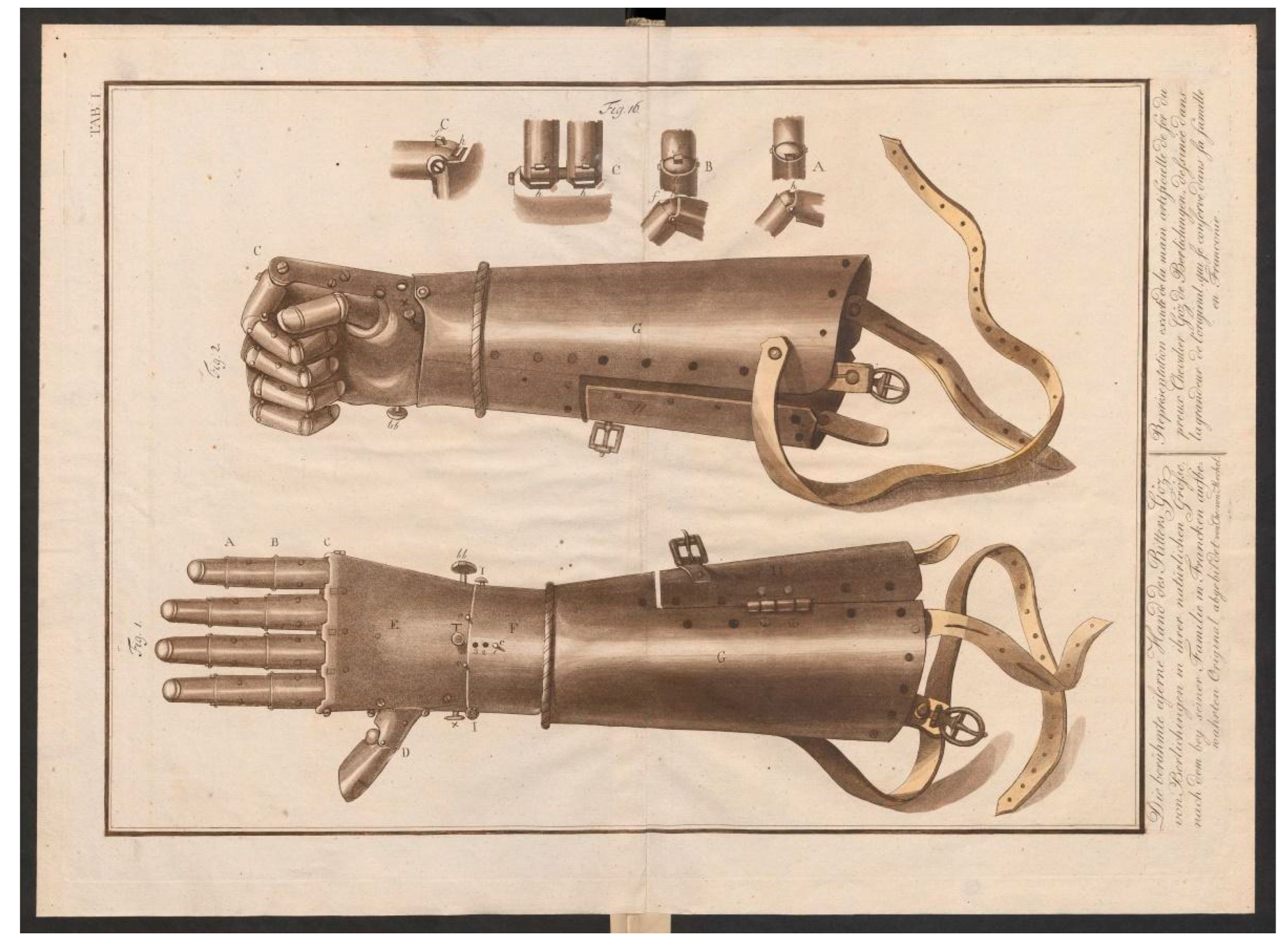
Figure A2.
Götz von Berlichingen´s second “Iron Hand”, overview of the mechanism of the fingers. Picture credit: Tabula II from Christian von Mechel´s book, 1815 [3], entitled: "Göz von Berlichingen´s eiserne Hand, nach dem inneren kunstreichen Mechanismus, und allen zu demselben gehörenden Theilen richtig abgezeichnet von Chr. von Mechel." ["Götz von Berlichingen's iron hand, after the inner elaborate mechanism, and all parts belonging to the same correctly drawn by Chr. von Mechel."]. Picture credit: Mechel, Christian von: Die eiserne Hand des tapfern deutschen Ritters Götz von Berlichingen: wie selbige noch bei seiner Familie in Franken aufbewahrt wird, sowohl von Aussen als von Innen dargestellt : nebst der Erklärung ihres für jene Zeiten [...]. Berlin : gedruckt bei Georg Decker..., 1815. ETH-Bibliothek Zürich, Rar 2224, https://doi.org/10.3931/e-rara-14841 (Public Domain Mark 1.0). .
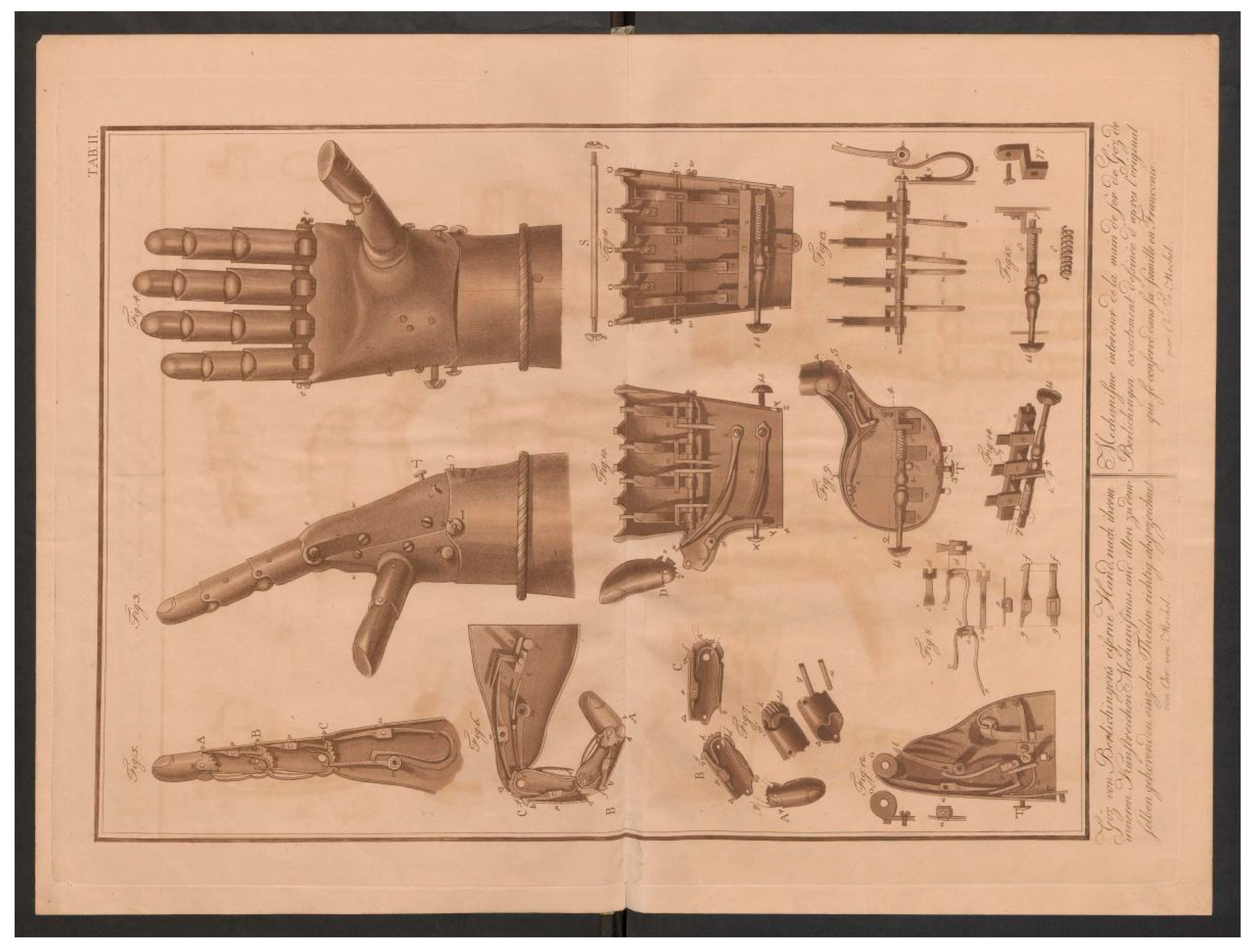
Figure A3.
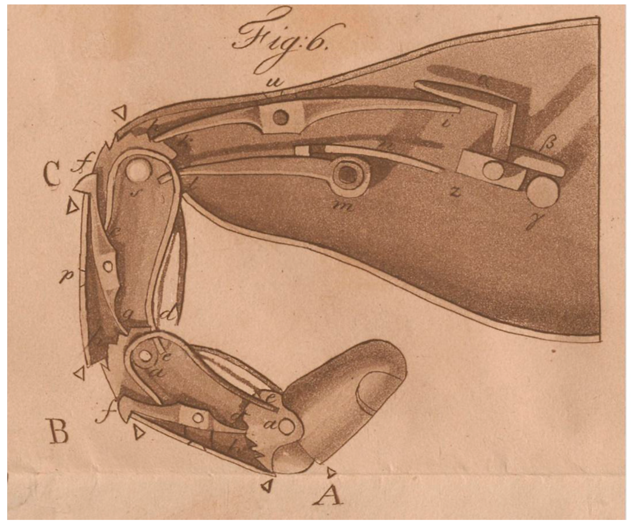
Götz von Berlichingen´s second “Iron Hand”, detail of the finger mechanism: A, B, C: phalanges. A is hollow and closed on all sides. B and C are hollow but open on one side to accommodate articular vertebrae. a: Pins. The pins unite the phalanges. In addition, the two springs e are placed around them and the pin S. At d, the springs e are provided with an opening Δ into which the lower part of the spring of the abutting link engages. f, g: Locking lever. p: Hinge head. h: Teeth. i, k: Locking lever in hand body. In i, the locking lever is still connected to other levers. u: hinge head. l, m: tension hook. n: Spring. α, β: lever. γ: pusher. z: shaft. Picture credit: Illustration 6 (entitled „Fig:6.“) enlarged from Tabula II (see Figure 2) of Christian von Mechel´s book , 1815 [3], entitled: "Die berühmte eiserne Hand des Ritters Göz von Berlichingen in ihrer natürlichen Größe, nach dem bey seiner Familie in Francken aufbewahrten Original abgebildet von Chr. von Mechel." [„The famous iron hand of the knight Götz von Berlichingen in its natural size, illustrated by Chr. von Mechel after the original kept with his family in Franconia.”]. Picture credit: Mechel, Christian von: Die eiserne Hand des tapfern deutschen Ritters Götz von Berlichingen: wie selbige noch bei seiner Familie in Franken aufbewahrt wird, sowohl von Aussen als von Innen dargestellt : nebst der Erklärung ihres für jene Zeiten [...]. Berlin : gedruckt bei Georg Decker..., 1815. ETH-Bibliothek Zürich, Rar 2224, https://doi.org/10.3931/e-rara-14841 (Public Domain Mark 1.0).
Figure A3.
Götz von Berlichingen´s second “Iron Hand”, detail of the finger mechanism: A, B, C: phalanges. A is hollow and closed on all sides. B and C are hollow but open on one side to accommodate articular vertebrae. a: Pins. The pins unite the phalanges. In addition, the two springs e are placed around them and the pin S. At d, the springs e are provided with an opening Δ into which the lower part of the spring of the abutting link engages. f, g: Locking lever. p: Hinge head. h: Teeth. i, k: Locking lever in hand body. In i, the locking lever is still connected to other levers. u: hinge head. l, m: tension hook. n: Spring. α, β: lever. γ: pusher. z: shaft. Picture credit: Illustration 6 (entitled „Fig:6.“) enlarged from Tabula II (see Figure 2) of Christian von Mechel´s book , 1815 [3], entitled: "Die berühmte eiserne Hand des Ritters Göz von Berlichingen in ihrer natürlichen Größe, nach dem bey seiner Familie in Francken aufbewahrten Original abgebildet von Chr. von Mechel." [„The famous iron hand of the knight Götz von Berlichingen in its natural size, illustrated by Chr. von Mechel after the original kept with his family in Franconia.”]. Picture credit: Mechel, Christian von: Die eiserne Hand des tapfern deutschen Ritters Götz von Berlichingen: wie selbige noch bei seiner Familie in Franken aufbewahrt wird, sowohl von Aussen als von Innen dargestellt : nebst der Erklärung ihres für jene Zeiten [...]. Berlin : gedruckt bei Georg Decker..., 1815. ETH-Bibliothek Zürich, Rar 2224, https://doi.org/10.3931/e-rara-14841 (Public Domain Mark 1.0).
References
- Otte, A. 3D Computer-Aided Design Reconstructions and 3D Multi-Material Polymer Replica Printings of the First “Iron Hand” of Franconian Knight Gottfried (Götz) von Berlichingen (1480–1562): An Overview. Prosthesis 2020, 2, 304–312. [Google Scholar] [CrossRef]
- Weinert, O.; Otte, A. 3-D CAD-Rekonstruktion der ersten “Eisernen Hand” des Reichsritters Gottfried von Berlichingen (1480–1562) [3D CAD reconstruction of the first “Iron Hand” of German knight Gottfried von Berlichingen (1480–1562)]. Arch. Kriminol. 2017, 240, 50–58. [Google Scholar]
- Otte, A.; Weinert, O.; Junk, S. 3-D CAD-Rekonstruktion der ersten “Eisernen Hand” des Reichsritters Gottfried von Berlichingen (1480–1562): 1. Fortsetzung: Funktionsprüfung mittels 3-D Druck. [3D CAD reconstruction of the first “Iron Hand” of German knight Gottfried von Berlichingen (1480–1562)—First continuation: Function test by means of 3D print]. Arch. Kriminol. 2017, 240, 185–192. [Google Scholar]
- Otte, A. Invasive versus non-invasive neuroprosthetics of the upper limb: Which way to go? Prosthesis 2020, 2, 237–239. [Google Scholar] [CrossRef]
- Weinert, O.; Otte, A. 3-D CAD-Rekonstruktion der ersten “Eisernen Hand” des Reichsritters Gottfried von Berlichingen (1480–1562)—2. Fortsetzung: Funktionsprüfung eines Umbaus zu einem sensomotorischen, controllergesteuerten intelligenten Fingersystem. [3D CAD reconstruction of the first “Iron Hand” of German knight Gottfried von Berlichingen (1480–1562)—second continuation: Functional test of a conversion to a sensorimotor, controller-controlled intelligent finger system]. Arch. Kriminol. 2019, 243, 126–132. [Google Scholar]
- Otte, A. Smart neuroprosthetics becoming smarter, but not for everyone? eClinicalMedicine 2018, 2–3, 11–12. [Google Scholar] [CrossRef] [PubMed]
- Otte, A.; Hazubski, S. Die erste “Eiserne Hand” des Reichsritters Gottfried von Berlichingen (1480–1562): Weitere 3-D CAD-Rekonstruktionen. [The first “Iron Hand” of German knight Gottfried von Berlichingen (1480–1562): Further 3D CAD reconstructions]. Arch. Kriminol. 2020, 246, 207–210. [Google Scholar]
- von Mechel, C. Die Eiserne Hand des Tapfern Deutschen Ritters Götz von Berlichingen [The Iron Hand of the Brave German Knight Götz von Berlichingen]; Georg Decker: Berlin, Germany, 1815. [Google Scholar]
- Otte, A. Christian von Mechel’s Reconstructive Drawings of the Second “Iron Hand” of Franconian Knight Gottfried (Götz) von Berlichingen (1480–1562). Prosthesis 2021, 3, 105–109. [Google Scholar] [CrossRef]
- Otte, A. Lessons Learnt from Götz of the Iron Hand. Prosthesis 2022, 4, 444–446. [Google Scholar] [CrossRef]
- G. Quasigroch. Die Handprothesen des fränkischen Reichsritters Götz von Berlichingen [The hand prostheses of the Frankish imperial knight Götz von Berlichingen]. Waffen- und Kostümkunde 1983, 103–120.
- J. Prusa. 3D Druck Handbuch. [3D printing manual]. 2022. https://www.prusa3d.com/downloads/manual/prusa3d_manual_mk3s_de.
- Schneider, KA. CAD-gestütztes Modell der inneren Mechanik der zweiten „Eisernen Hand“ des Götz von Berlichingen. Offenburg University, Offenburg, Germany, 2024.
- Otte, A. Johann Wolfgang von Goethe, Götz von Berlichingen, and the “Iron Hands”. Prosthesis 2024, 6, 506–508. [Google Scholar] [CrossRef]
Figure 1.
Complete 2D drawing of the index finger, lateral view.
Figure 2.
(a) Different variants of the spring inside the phalanx that were printed and tested, (b) final version of the spring (cf. “c d e” in Figure A3, Appendix A).
Figure 2.
(a) Different variants of the spring inside the phalanx that were printed and tested, (b) final version of the spring (cf. “c d e” in Figure A3, Appendix A).
Figure 3.
Technical drawing of the reconstructed index finger of the second “Iron Hand”.
Figure 4.
3D-printed model of the index finger of the second “Iron Hand” at a scale of 2:1.
Figure 5.
Modified spring (cf. “n” in Figure A3, Appendix A) with tensioning hook (cf. “l m” in Figure A3, Appendix A).
Figure 5.
Modified spring (cf. “n” in Figure A3, Appendix A) with tensioning hook (cf. “l m” in Figure A3, Appendix A).
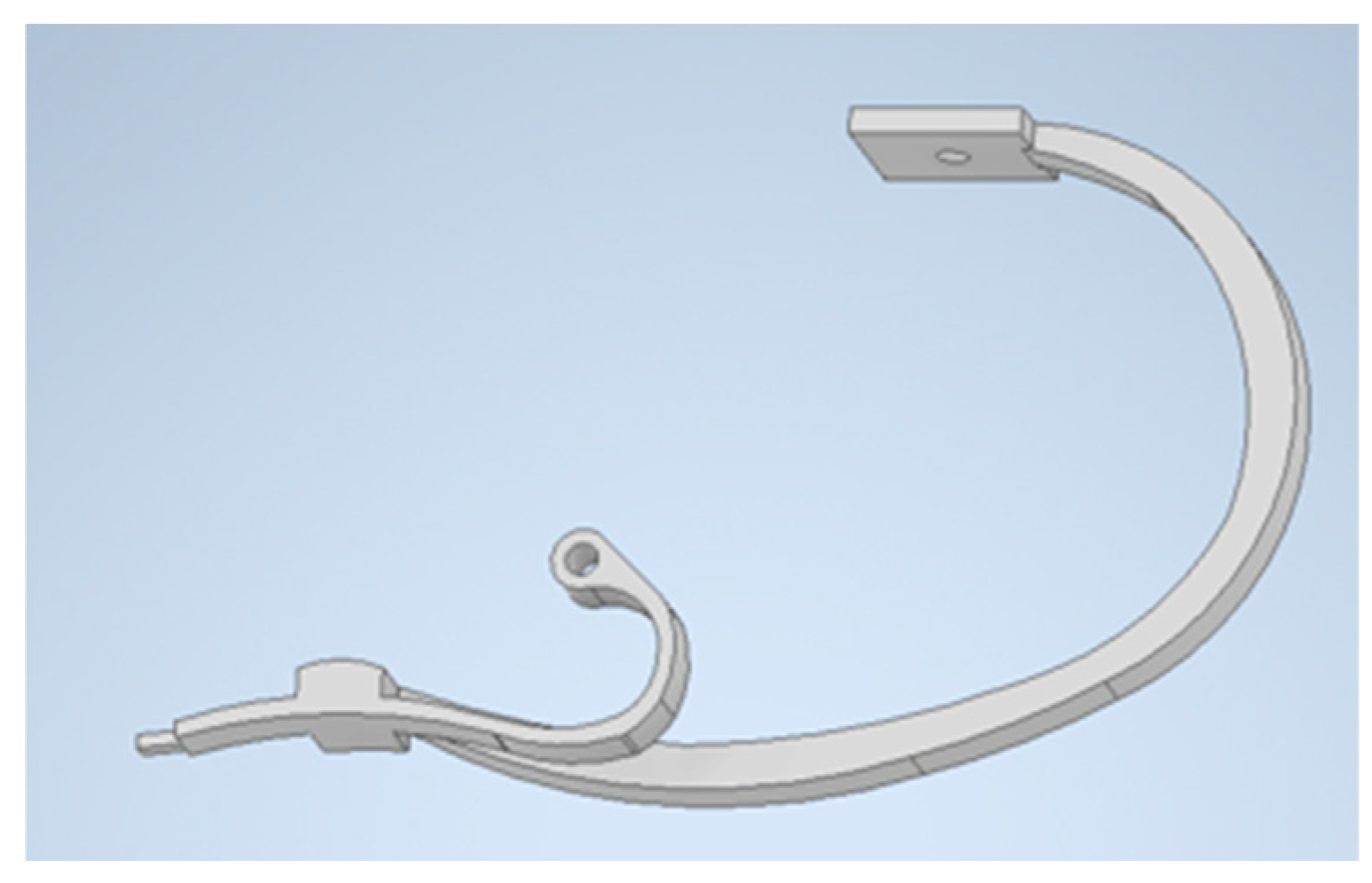
Figure 6.
Optimized model of the reconstruction of the index finger of the second “Iron Hand”.
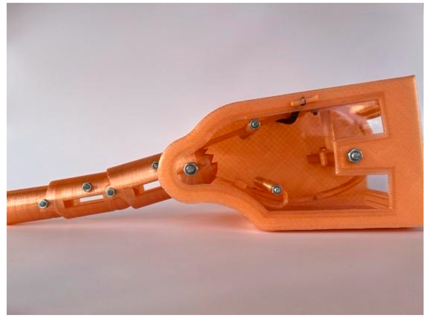
Figure 7.
Close-up of the inner mechanics of the housing.
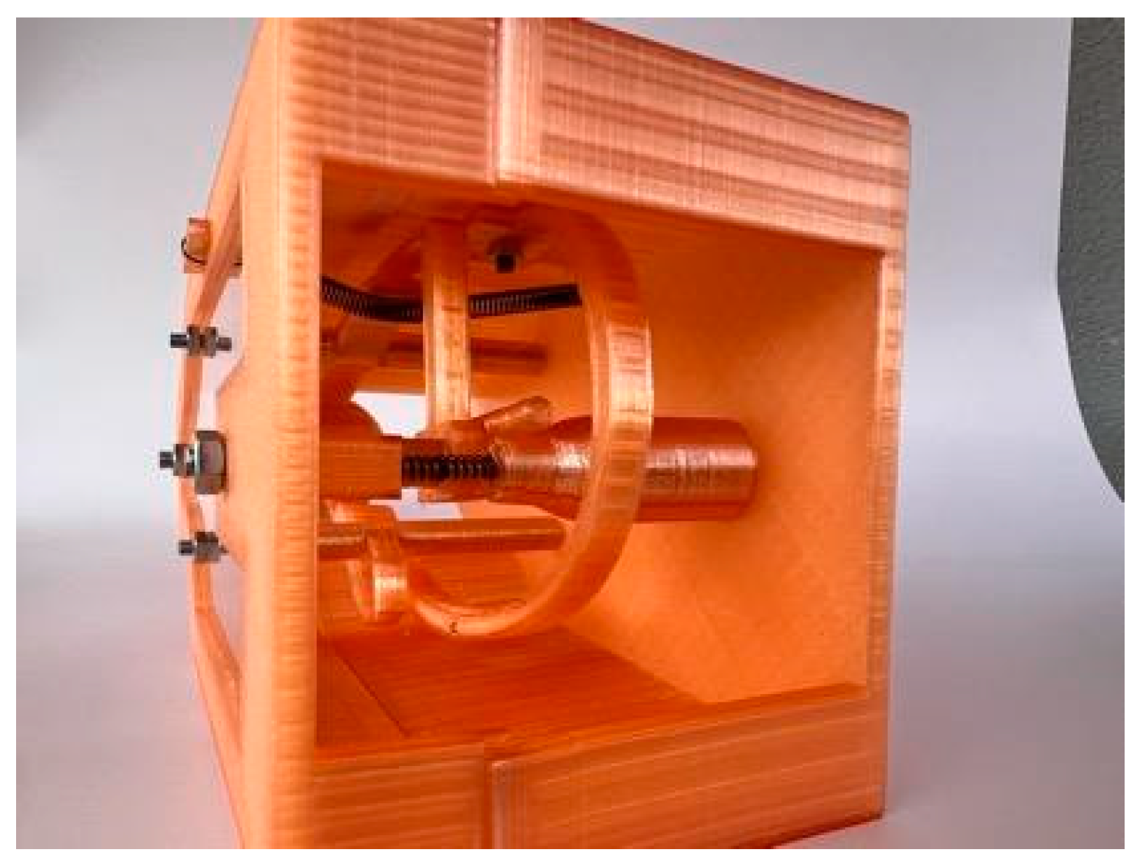
Figure 8.
Flexion position of the optimized model.
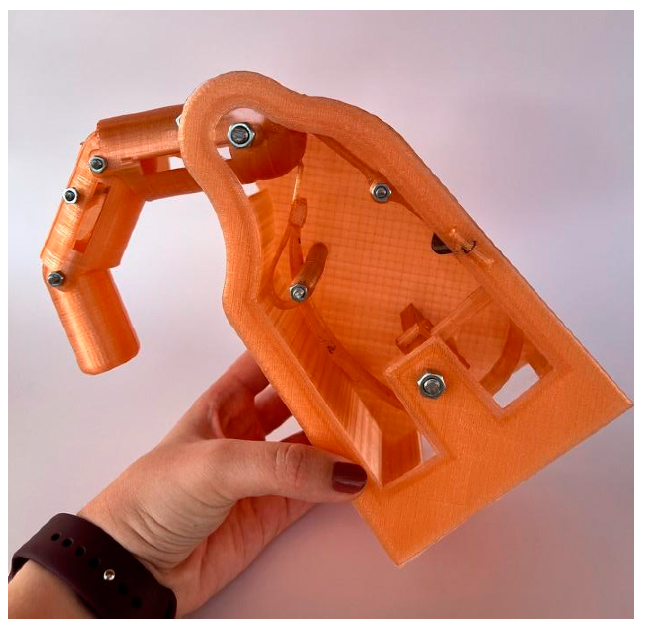
Figure 9.
FEM analysis of the spring.
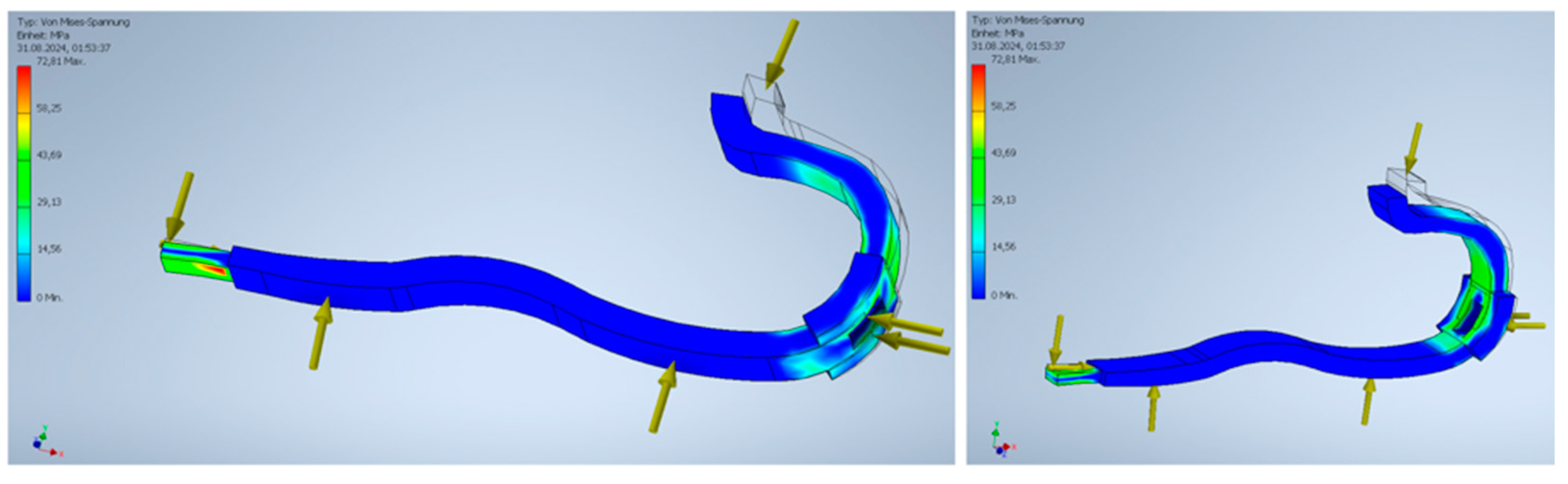
Figure 11.
Manufacturing of the spring from steel.

Figure 12.
Presentation of the results from different perspectives: the 0.75 mm thick spring on the left, the 1.2 mm thick spring in the middle, and the 1.8 mm thick spring on the right.
Figure 12.
Presentation of the results from different perspectives: the 0.75 mm thick spring on the left, the 1.2 mm thick spring in the middle, and the 1.8 mm thick spring on the right.
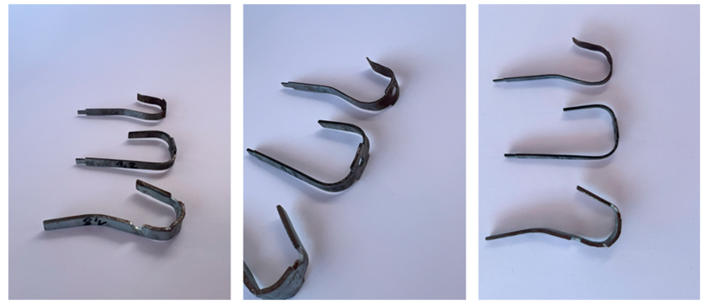
Figure 13.
Components at a scale of 2:1 compared to a scale of 1:1.
Disclaimer/Publisher’s Note: The statements, opinions and data contained in all publications are solely those of the individual author(s) and contributor(s) and not of MDPI and/or the editor(s). MDPI and/or the editor(s) disclaim responsibility for any injury to people or property resulting from any ideas, methods, instructions or products referred to in the content. |
© 2024 by the authors. Licensee MDPI, Basel, Switzerland. This article is an open access article distributed under the terms and conditions of the Creative Commons Attribution (CC BY) license (http://creativecommons.org/licenses/by/4.0/).
Copyright: This open access article is published under a Creative Commons CC BY 4.0 license, which permit the free download, distribution, and reuse, provided that the author and preprint are cited in any reuse.


