
Submitted:
21 November 2024
Posted:
22 November 2024
You are already at the latest version
Abstract
This paper provides a comprehensive analysis of geothermal heat pump systems (GHPS), focusing on their advantages, disadvantages, key components, types, and ground heat exchangers (GHEs). It presents a detailed review of closed-loop GHE configurations, emphasizing their impact on heat transfer performance and installation costs. The findings show that helical GHEs offer superior thermal performance with reduced drilling depths and costs, while coaxial GHEs, particularly with steel tubes, enhance heat transfer efficiency and reduce borehole depth. Cost-effective solutions, such as W-type GHEs, deliver comparable thermal performance to more expensive configurations. Triple U-tube and spiral GHEs demonstrate high efficiency, balancing performance with economic considerations. The most commonly used borehole geometries are single or double U-tube configurations, while coaxial designs provide additional benefits in specific applications. These insights guide the optimization of vertical ground heat exchangers, improving performance, cost-effectiveness, and long-term sustainability in GHPS installations.
Keywords:
1. Introduction
1-1. Advantages
1-2. Disadvantages
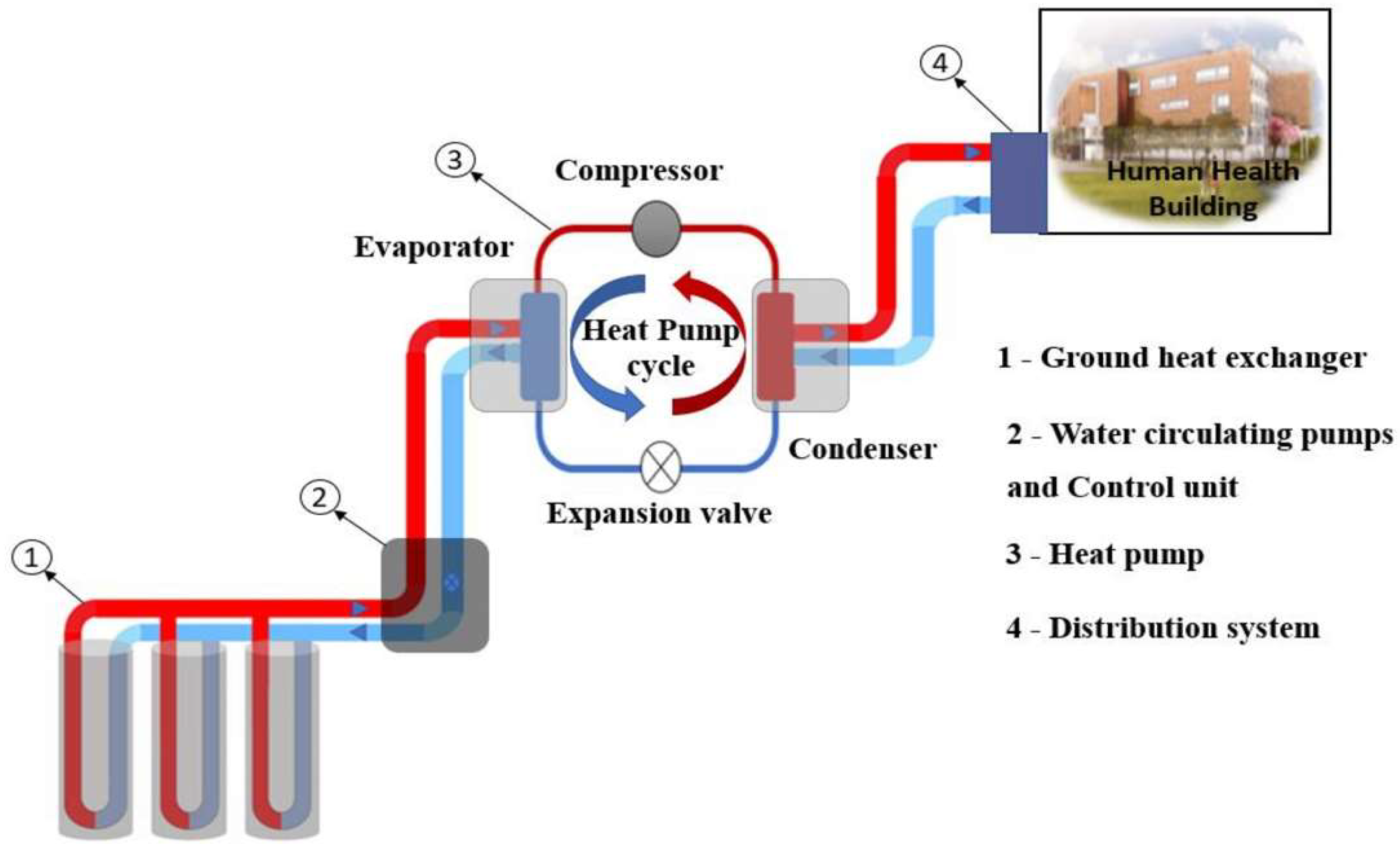
2-. GHPS Components
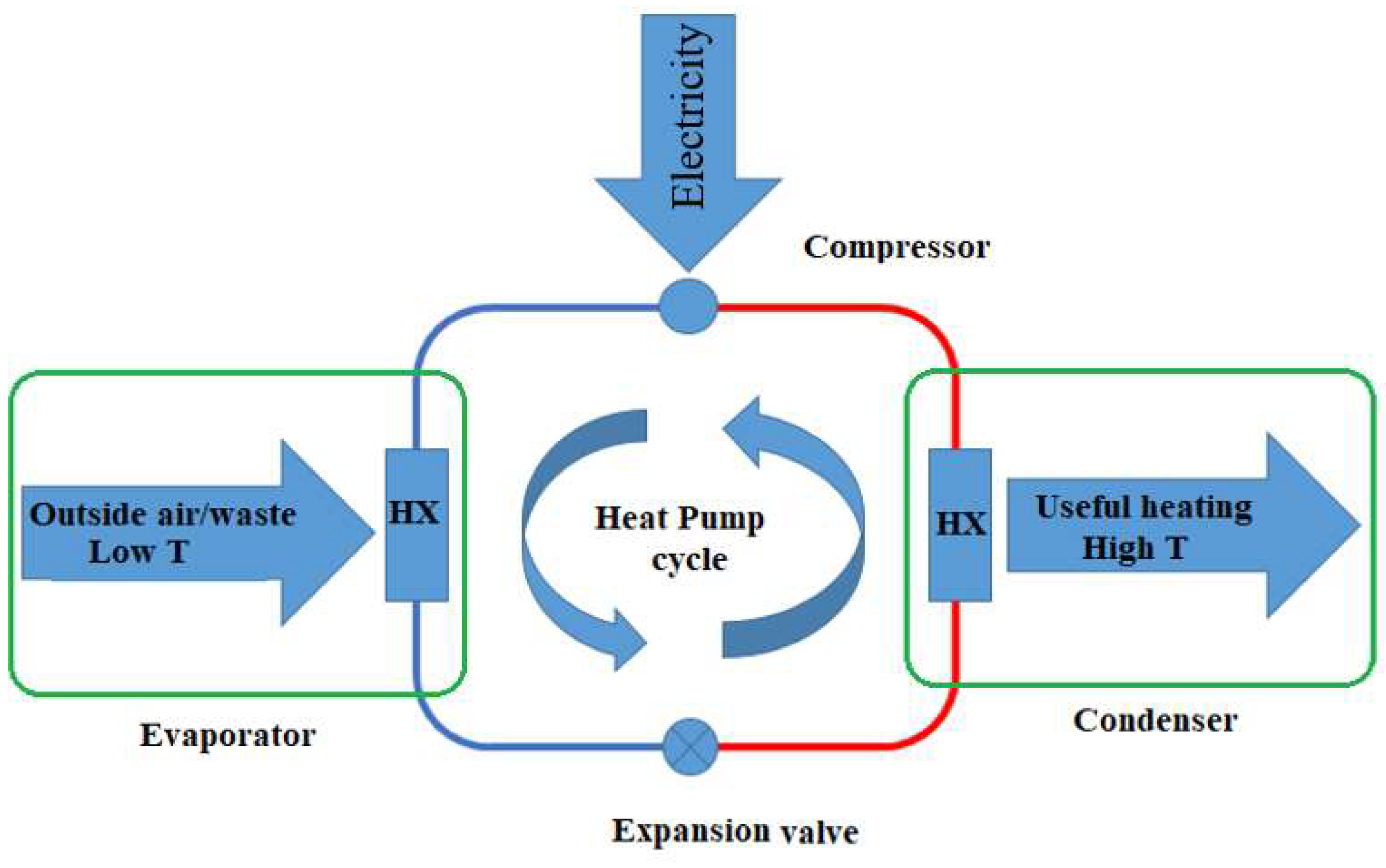
2-1. Heat Pump
2.-2 Distribution System
2-3 . Ground Heat Exchanger
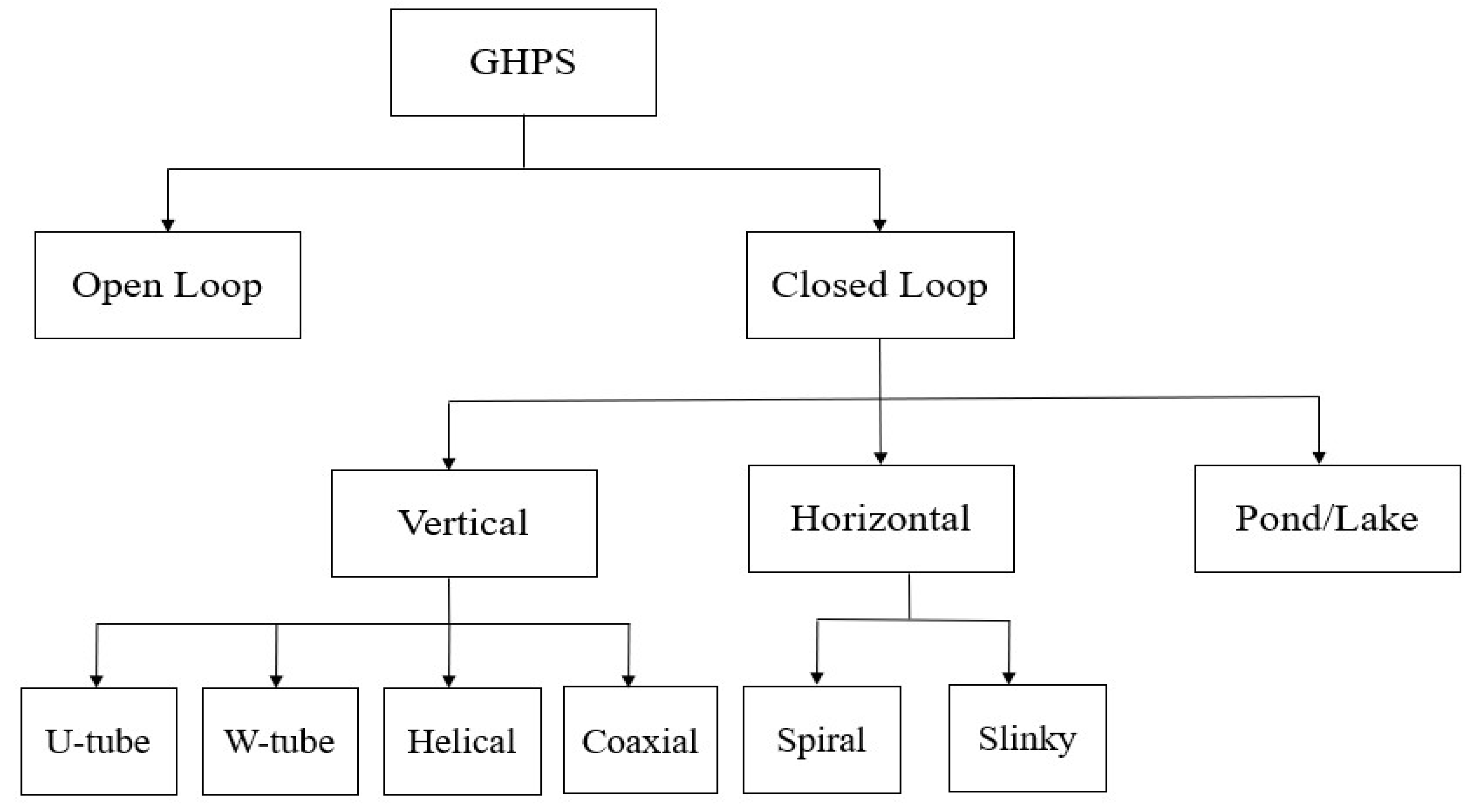
3. GHPS Types
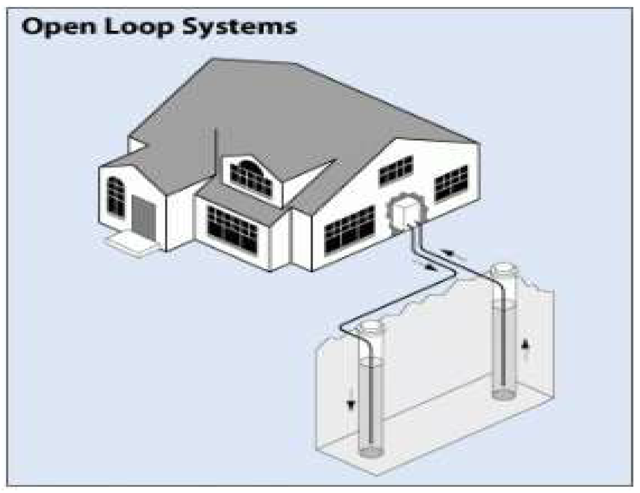
3.-1 Open Loop Systems
3.-2 . Closed Loop Systems
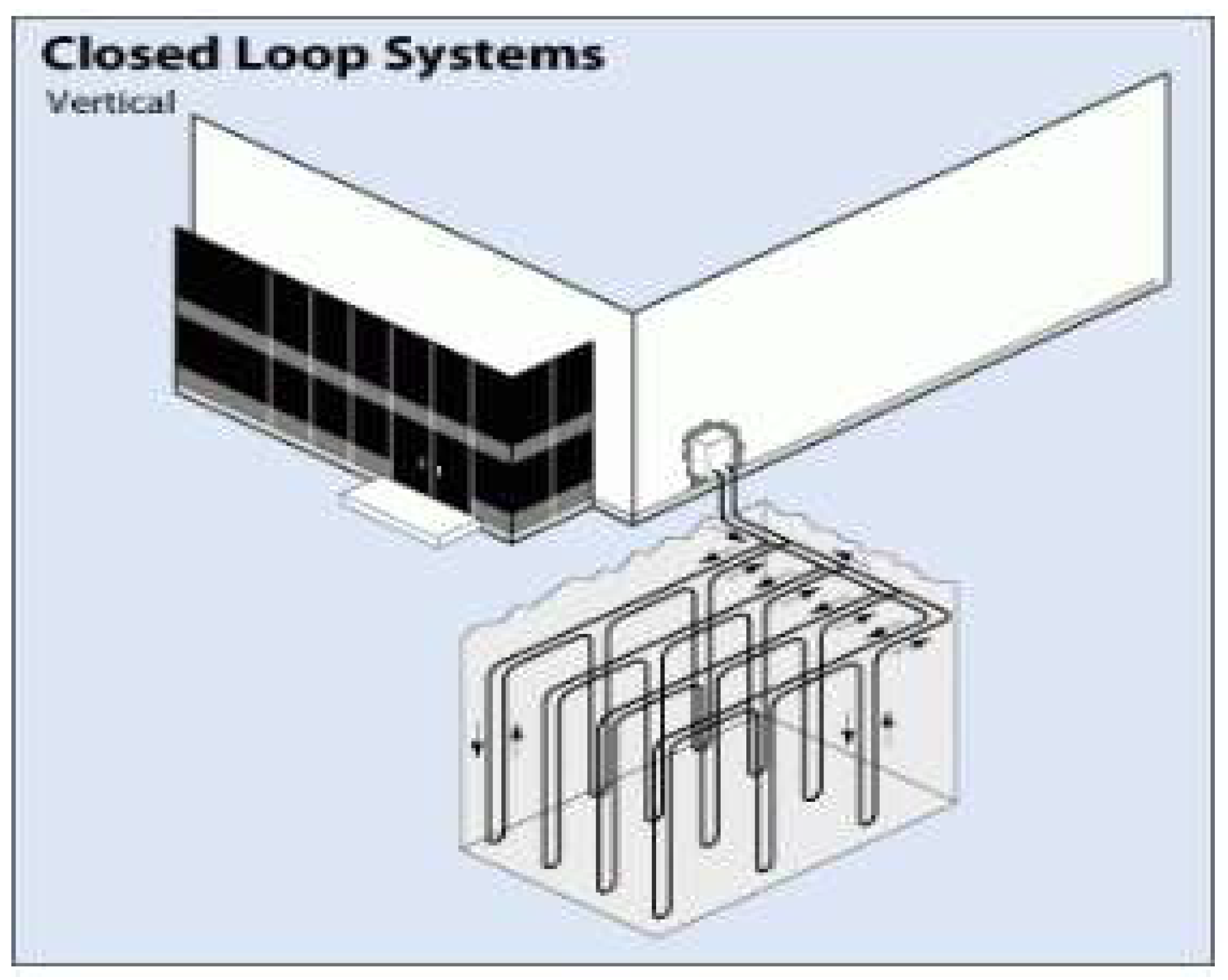
3.-2-1 Vertical Configuration
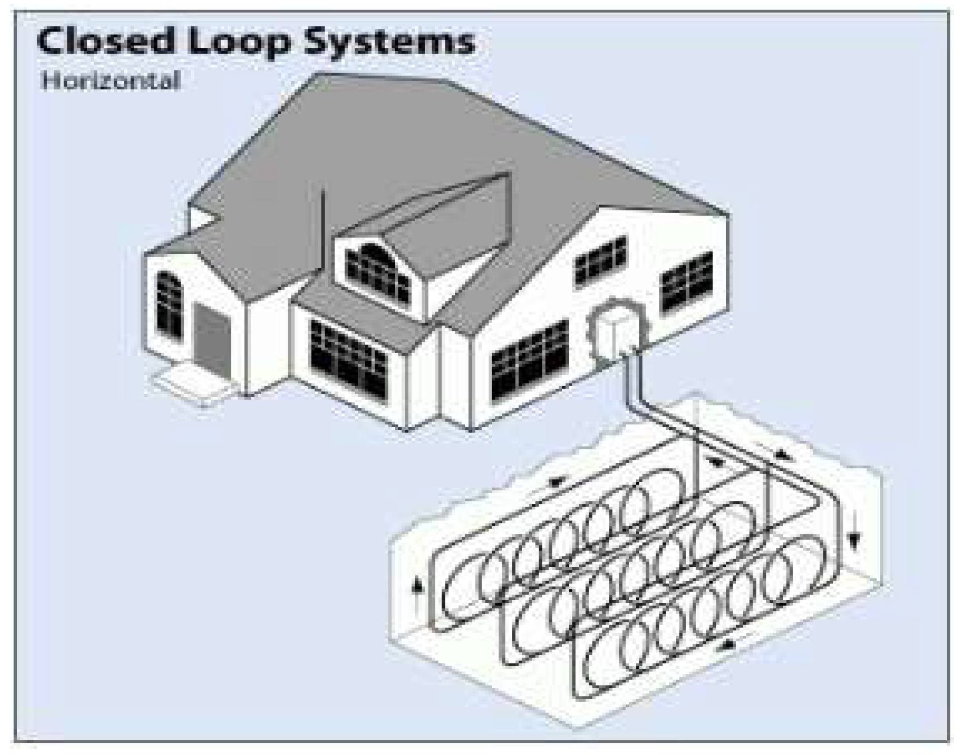
3-2-2. Horizontal Configuration
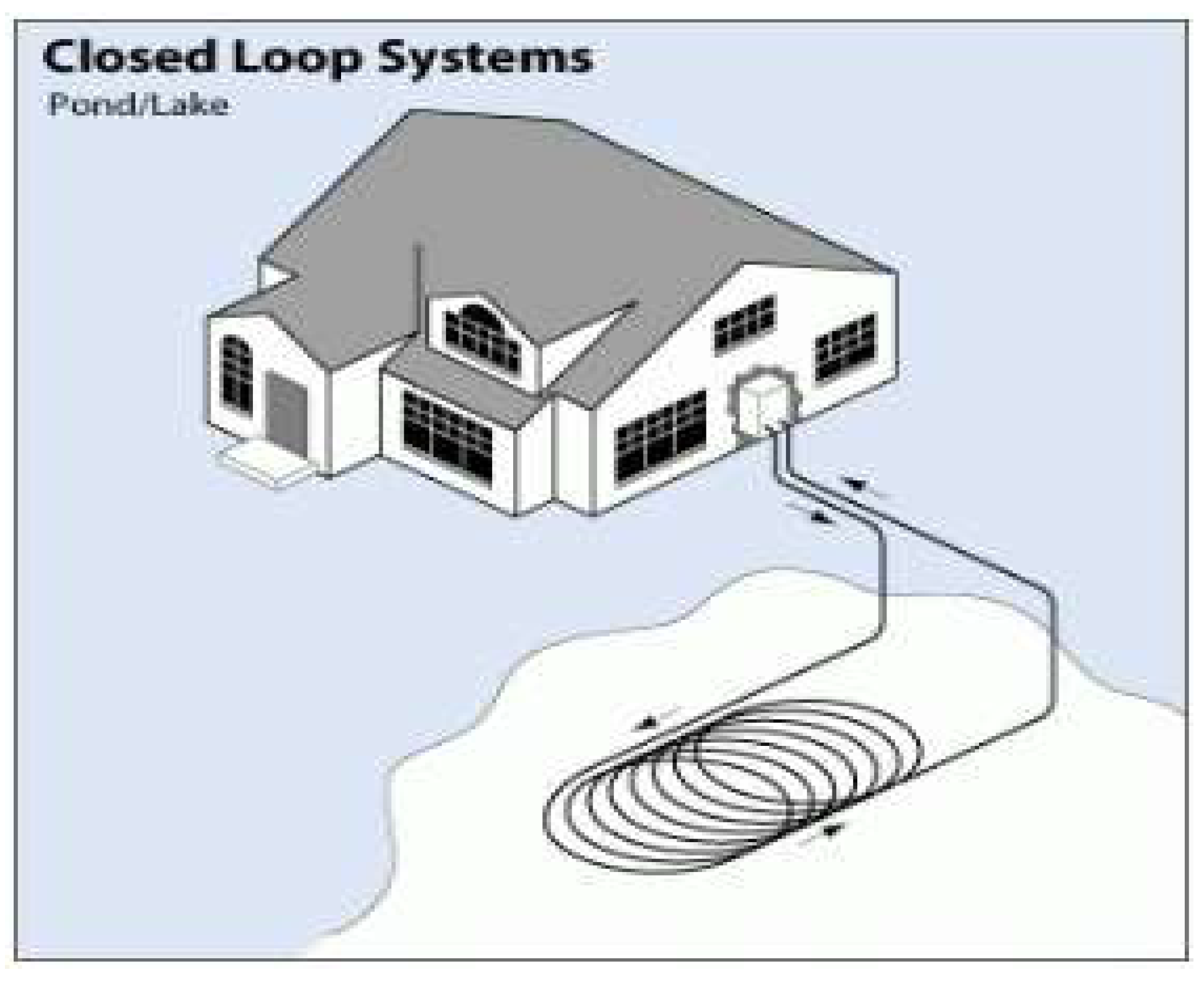
3-2-3. Pond/Lake Configuration
3-3. Comparison of closed-loop and open-loop geothermal heat pump systems
4. Discussion: Comparison of Closed-Loop Ground Heat Exchanger Configurations
5. Conclusions
References
- K.A.A. Salhein, Modeling and Control of Heat Transfer in a Single Vertical Ground Heat Exchanger for a Geothermal Heat Pump System. 2023: Oakland University.
- A.M. Omer, "Ground-source heat pumps systems and applications", Renewable and sustainable energy reviews. Vol. 12, no. 2, pp. 344-371, 2008. [CrossRef]
- E. SAVER. Geothermal Heat Pumps. [cited November 12, 2024]; Available from: https://www.energy.gov/energysaver/geothermal-heat-pumps.
- K. Salhein, J. Ashraf, and M. Zohdy, "Output temperature predictions of the geothermal heat pump system using an improved grey prediction model", Energies. Vol. 14, no. 16, pp. 5075, 2021. [CrossRef]
- United States General Accounting Office, Geothermal Energy: Outlook Limited for Some Uses But Promising for Geothermal Heat Pumps. 1994.
- A.J. Philippacopoulos and M.L. Berndt, "Influence of Debonding in Ground Heat Exchangers Used With Geothermal Heat Pumps", Geothermics. Vol. 30, no. 5, pp. 527-545, 2001. [CrossRef]
- K. Salhein, C. Kobus, and M. Zohdy, "Forecasting installation capacity for the top 10 countries utilizing geothermal energy by 2030", Thermo. Vol. 2, no. 4, pp. 334-351, 2022. [CrossRef]
- A. Mustafa Omer, "Ground-source heat pumps systems and applications", Renewable and Sustainable Energy Reviews. Vol. 12, no. 2, pp. 344-371, 2008. [CrossRef]
- J. Parsons. What is Geothermal Energy And How Can I Heat/Cool My House With It? 2020 [cited November 07, 2024]; Available from: https://www.climatemaster.com/homeowner/news/geothermal-energy/geothermal-energy/2020-12-11-what-is-geothermal-energy-and-how-can-i-heat-cool-my-house-with-it.
- E.Y. Alhawsawi, K. Salhein, and M.A. Zohdy, "A Comprehensive Review of Existing and Pending University Campus Microgrids", Energies. Vol. 17, no. 10, pp. 2425, 2024. [CrossRef]
- M. Zogg, "History of heat pumps-Swiss contributions and international milestones". 2008.
- G. Heat, "Geothermal Energy Outlook Limited for Some Uses but Promising for", United States General Accounting Office: Washington, DC, USA. June 03, 1994.
- K. Salhein, C. Kobus, and M. Zohdy, "Heat Transfer Control Mechanism in a Vertical Ground Heat Exchanger: A Novel Approach". Vol. 5, pp. 59-90, 2023.
- H. Miles. Heat Pump vs. Geothermal Systems: Which is Best? 2021 [cited November 07, 2024]; Available from: https://homeinspectioninsider.com/heat-pump-vs-geothermal-systems-which-is-best/.
- Greensleeves Technologies Corp. CO2 Emissions And Geothermal. 2018 [cited November 07, 2024]; Available from: https://www.greensleevestech.com/co2-emissions-and-geothermal/.
- K. Salhein, C. Kobus, and M. Zohdy, "Control of heat transfer in a vertical ground heat exchanger for a geothermal heat pump system", Energies. Vol. 15, no. 14, pp. 5300, 2022. [CrossRef]
- Manitoba Geothermal Energy Alliance. The Forks. [cited November 07, 2024]; Available from: https://www.mgea.ca/lead-project/the-forks/.
- H. Salaverry. Geothermal heat pumps in the U.S. November 20, 2019 [cited November 08, 2024]; Available from: https://storymaps.arcgis.com/stories/f4e7c478b90c49a5bf1fab8b3d4c8fe1.
- Office of Energy Efficiency & Renewable Energy, IEA 2020 U.S. Geothermal Report. 2021.
- E.K. Akpinar and A. Hepbasli, "A comparative study on exergetic assessment of two ground-source (geothermal) heat pump systems for residential applications", Building and Environment. Vol. 42, no. 5, pp. 2004-2013, 2007. [CrossRef]
- S. Noel. Geothermal heat pump cost. April 29, 2024 [cited November 08, 2024]; Available from: https://homeguide.com/costs/geothermal-heat-pump-cost.
- B. Miller. 17 Geothermal Heat Pump Pros and Cons. 2019 [cited November 08, 2024]; Available from: https://greengarageblog.org/17-geothermal-heat-pump-pros-and-cons#:~:text=The%20installation%20of%20a%20geothermal%20heat%20pump%20is,any%20gardens%20that%20may%20be%20on%20your%20property.
- X. SONG, Z. WEN, and J. SI, "CFD numerical simulation of a U-tube ground heat exchanger used in ground source heat pumps", Chinese Journal of Engineering. Vol. 29, no. 3, pp. 329-333, 2007.
- H. Zhou, J. Lv, and T. Li, "Applicability of the pipe structure and flow velocity of vertical ground heat exchanger for ground source heat pump", Energy and Buildings. Vol. 117, pp. 109-119, 2016. [CrossRef]
- M. Li and A.C. Lai, "Review of analytical models for heat transfer by vertical ground heat exchangers (GHEs): A perspective of time and space scales", Applied Energy. Vol. 151, pp. 178-191, 2015. [CrossRef]
- K. Salhein, et al., "Heat Transfer Performance Factors in a Vertical Ground Heat Exchanger for a Geothermal Heat Pump System", Energies. Vol. 17, no. 19, pp. 5003, 2024. [CrossRef]
- G. Florides and S. Kalogirou, "Ground heat exchangers—A review of systems, models and applications", Renewable energy. Vol. 32, no. 15, pp. 2461-2478, 2007.
- Energy Smart Alternatives. How Long Does It Take To Install A Geothermal System? [cited November 08, 2024]; Available from: https://energysmartalternatives.com/2016/03/how-long-does-it-take-to-install-a-geothermal-system/#:~:text=Installations%20in%20new%20construction%20typically%20take%20longer%20due,Permitting%20and%20Design%20%E2%80%93%202%20to%203%20Weeks.
- M. Planck, Treatise on Thermodynamics. 1945: Dover Publications.
- A.A.B. III. Open-Loop vs. Closed-Loop Ground Source Heat Pumps. December 7, 2023 [cited Nonvember 12, 2024]; Available from: https://www.greenbuildingadvisor.com/article/open-loop-vs-closed-loop-ground-source-heat-pumps.
- Dandelion. Open Loop vs Closed Loop Geothermal Systems. March 16, 2020 [cited November 12, 2024]; Available from: https://dandelionenergy.com/open-loop-vs-closed-loop-geothermal-systems.
- B. Stout. The Pros and Cons of Geothermal Heat Pumps. Nov. 06, 2023 [cited November 12, 2024]; Available from: https://www.familyhandyman.com/article/the-pros-and-cons-of-geothermal-heat-pumps/.
- M. Veggeberg. The Pros and Cons of Geothermal Heat Pumps. October 30, 2024 [cited November 12, 2024]; Available from: https://www.tetra.com/blog/the-pros-and-cons-of-geothermal-heat-pumps.
- Jacob. Open Loop Geothermal is Great But Exclusive. November 22, 2023 [cited November 13, 2023]; Available from: https://iwae.com/resources/articles/open-loop-geothermal-great-exclusive.html.
- F.L. Rashid, et al., "Ground heat exchanger in different configuration: Review of recent advances and development", Geoenergy Science and Engineering. Vol. 227, pp. 211872, 2023. [CrossRef]
- J. Chen, et al., "Simulation and experimental analysis of optimal buried depth of the vertical U-tube ground heat exchanger for a ground-coupled heat pump system", Renewable energy. Vol. 73, pp. 46-54, 2015. [CrossRef]
- L. Yang, et al., "Effect of buried depth on thermal performance of a vertical U-tube underground heat exchanger", Open Physics. Vol. 19, no. 1, pp. 327-330, 2021. [CrossRef]
- A. Casasso and R. Sethi, "Efficiency of closed loop geothermal heat pumps: A sensitivity analysis", Renewable Energy. Vol. 62, pp. 737-746, 2014. [CrossRef]
- S. Focaccia and F. Tinti, "An innovative Borehole Heat Exchanger configuration with improved heat transfer", Geothermics. Vol. 48, pp. 93-100, 2013. [CrossRef]
- G. Pei and L. Zhang, "Heat transfer analysis of underground U-type heat exchanger of ground source heat pump system", SpringerPlus. Vol. 5, pp. 1-15, 2016. [CrossRef]
- Y. Li, et al., "Evaluation of thermal short-circuiting and influence on thermal response test for borehole heat exchanger", Geothermics. Vol. 50, pp. 136-147, 2014. [CrossRef]
- A. Gultekin, M. Aydin, and A. Sisman, "Thermal performance analysis of multiple borehole heat exchangers", Energy Conversion and Management. Vol. 122, pp. 544-551, 2016. [CrossRef]
- S.J. Self, B.V. Reddy, and M.A. Rosen, "Geothermal heat pump systems: Status review and comparison with other heating options", Applied energy. Vol. 101, pp. 341-348, 2013. [CrossRef]
- Z. Sagia, A. Stegou, and C. Rakopoulos, "Borehole resistance and heat conduction around vertical ground heat exchangers", The open chemical engineering journal. Vol. 6, no. 1, 2012. [CrossRef]
- B. Sailer, D.M. Taborda, and J. Keirstead. Assessment of design procedures for vertical borehole heat exchangers. in PROCEEDINGS, Fortieth Workshop on Geothermal Reservoir Engineering. 2015.
- Z. Zheng, W. Wang, and C. Ji, "A study on the thermal performance of vertical U-tube ground heat exchangers", Energy Procedia. Vol. 12, pp. 906-914, 2011. [CrossRef]
- M.D. Smith and R.L. Perry, "Borehole grouting: field studies and thermal performance testing", ASHRAE Transactions. Vol. 105, pp. 451, 1999.
- H. Zeng, N. Diao, and Z. Fang, "Heat transfer analysis of boreholes in vertical ground heat exchangers", International journal of heat and mass transfer. Vol. 46, no. 23, pp. 4467-4481, 2003. [CrossRef]
- C. Xia, et al., "Experimental study on geothermal heat exchangers buried in diaphragm walls", Energy and Buildings. Vol. 52, pp. 50-55, 2012. [CrossRef]
- S. Yoon, et al., "Evaluation of the thermal efficiency and a cost analysis of different types of ground heat exchangers in energy piles", Energy Conversion and Management. Vol. 105, pp. 393-402, 2015. [CrossRef]
- J. Acuña, Distributed thermal response tests: New insights on U-pipe and Coaxial heat exchangers in groundwater-filled boreholes. 2013, KTH Royal Institute of Technology.
- J. Raymond, S. Mercier, and L. Nguyen, "Designing coaxial ground heat exchangers with a thermally enhanced outer pipe", Geothermal Energy. Vol. 3, pp. 1-14, 2015. [CrossRef]
- A. Zarrella, A. Capozza, and M. De Carli, "Performance analysis of short helical borehole heat exchangers via integrated modelling of a borefield and a heat pump: A case study", Applied Thermal Engineering. Vol. 61, no. 2, pp. 36-47, 2013. [CrossRef]
- K. Chen, et al., "Numerical study on the heat performance of enhanced coaxial borehole heat exchanger and double U borehole heat exchanger", Applied Thermal Engineering. Vol. 203, pp. 117916, 2022.
- X. Song, et al., "Heat extraction performance simulation for various configurations of a downhole heat exchanger geothermal system", Energy. Vol. 141, pp. 1489-1503, 2017. [CrossRef]
- A.A. Mehrizi, et al., "Energy pile foundation simulation for different configurations of ground source heat exchanger", International Communications in Heat and Mass Transfer. Vol. 70, pp. 105-114, 2016. [CrossRef]
- G.A. Florides, P. Christodoulides, and P. Pouloupatis, "Single and double U-tube ground heat exchangers in multiple-layer substrates", Applied energy. Vol. 102, pp. 364-373, 2013. [CrossRef]
- Office of Energy Efficiency & Renewable Energy. Geothermal Technologies Office. [cited Dec 03, 2022]; Available from: https://www.energy.gov/eere/geothermal/geothermal-technologies-office.
- A. Shtym and I. Zhurmilova. Ground heat exchangers of geothermal heat pumps and analysis of their constructive features and types. in 2017 International Conference on Industrial Engineering, Applications and Manufacturing (ICIEAM). 2017. IEEE.
- B. Tang and H. Nowamooz, "Factors influencing the performance of shallow Borehole Heat Exchanger", Energy conversion and management. Vol. 181, pp. 571-583, 2019.
- L. Fang, et al., "Study on the efficiency of single and double U-tube heat exchangers", Procedia Engineering. Vol. 205, pp. 4045-4051, 2017. [CrossRef]
- R. Brown. Geothermal heat pumps: Everything you need to know. Mar 6, 2023 [cited November 13, 2024]; Available from: https://www.energysage.com/heat-pumps/geothermal-heat-pumps/.
- M.-J. Kim, et al., "Thermal performance evaluation and parametric study of a horizontal ground heat exchanger", Geothermics. Vol. 60, pp. 134-143, 2016. [CrossRef]
- Geothermal Solutions. Pond Loop. [cited November 14, 2024]; Available from: http://www.geothermalsolutions.net/pond-loop-geothermal-pond-loop-loops.html.
- R.V. Bibber. Everything You Need to Know About Geothermal Heat Pumps. June 05, 2023 [cited November 14, 2024]; Available from: https://www.familyhandyman.com/article/everything-you-need-to-know-about-geothermal-heat-pumps/#:~:text=Pond%2FLake%20System%20This%20system%20draws%20heat%20from%20water,coils%20anchored%20on%20racks%20about%2010%20ft.%20deep.
- P. Cui, H. Yang, and Z. Fang, "Numerical analysis and experimental validation of heat transfer in ground heat exchangers in alternative operation modes", Energy and buildings. Vol. 40, no. 6, pp. 1060-1066, 2008. [CrossRef]
- G.A. Florides, et al. Vertical and Horizontal Ground Heat Exchanger Modeling. in World Renewable Energy Congress 2013. 2013.
- C. Sáez Blázquez, et al., "Efficiency analysis of the main components of a vertical closed-loop system in a borehole heat exchanger", Energies. Vol. 10, no. 2, pp. 201, 2017. [CrossRef]
- E.D. Kerme and A.S. Fung, "Heat transfer analysis of single and double U-tube borehole heat exchanger with two independent circuits", Journal of Energy Storage. Vol. 43, pp. 103141, 2021. [CrossRef]
- A. Miyara, et al., "Experimental study of several types of ground heat exchanger using a steel pile foundation", Renewable Energy. Vol. 36, no. 2, pp. 764-771, 2011. [CrossRef]
- A. Yavuzturk and A.D. Chiasson, "Performance analysis of U-tube, concentric tube, and standing column well ground heat exchangers using a system simulation approach", ASHRAE transactions. Vol. 108, pp. 925, 2002.
- J. Gao, et al., "Thermal performance and ground temperature of vertical pile-foundation heat exchangers: A case study", Applied Thermal Engineering. Vol. 28, no. 17-18, pp. 2295-2304, 2008. [CrossRef]
- A. Zarrella, A. Capozza, and M. De Carli, "Analysis of short helical and double U-tube borehole heat exchangers: A simulation-based comparison", Applied Energy. Vol. 112, pp. 358-370, 2013. [CrossRef]
- H. Javadi, et al., "Performance analysis of helical ground heat exchangers with different configurations", Applied Thermal Engineering. Vol. 154, pp. 24-36, 2019. [CrossRef]
- B. Harris, et al., "Analysis of the transient performance of coaxial and u-tube borehole heat exchangers", Geothermics. Vol. 101, pp. 102319, 2022. [CrossRef]
- B. Harris, et al., "A numerical study on the intermittent operation of u-tube and coaxial borehole heat exchangers", Geothermics. Vol. 121, pp. 103030, 2024. [CrossRef]
- T. Rajeh, et al., "Modeling and techno-economic comparison of two types of coaxial with double U-tube ground heat exchangers", Applied Thermal Engineering. Vol. 225, pp. 120221, 2023. [CrossRef]
- T. Sliwa and M. Rosen, "Efficiency analysis of borehole heat exchangers as grout varies via thermal response test simulations", Geothermics. Vol. 69, pp. 132-138, 2017. [CrossRef]
- B. Bezyan, S. Porkhial, and A.A. Mehrizi, "3-D simulation of heat transfer rate in geothermal pile-foundation heat exchangers with spiral pipe configuration", Applied Thermal Engineering. Vol. 87, pp. 655-668, 2015. [CrossRef]
- P. Kushwaha, "PHYSICAL MODEL TO INCREASE THE DISCHARGE TIME OF TES SYSTEM USING U AND W TUBE".
- S. Yoon, S.-R. Lee, and G.-H. Go, "A numerical and experimental approach to the estimation of borehole thermal resistance in ground heat exchangers", Energy. Vol. 71, pp. 547-555, 2014. [CrossRef]
- B. Asgari, M. Habibi, and A. Hakkaki-Fard, "Assessment and comparison of different arrangements of horizontal ground heat exchangers for high energy required applications", Applied Thermal Engineering. Vol. 167, pp. 114770, 2020. [CrossRef]
- T. Kurevija and K. Strpić, "Hydraulic and thermogeological design differences between two-loop vertical and inclined coaxial borehole heat exchangers", Renewable energy. Vol. 117, pp. 314-323, 2018. [CrossRef]
- C. Lee, et al., "Comparison of effective thermal conductivity in closed-loop vertical ground heat exchangers", Applied Thermal Engineering. Vol. 31, no. 17-18, pp. 3669-3676, 2011. [CrossRef]
- S. Yoon, S.-R. Lee, and G.-H. Go, "Evaluation of thermal efficiency in different types of horizontal ground heat exchangers", Energy and Buildings. Vol. 105, pp. 100-105, 2015. [CrossRef]
- C.S.A. Chong, et al., "Simulation of thermal performance of horizontal slinky-loop heat exchangers for ground source heat pumps", Applied Energy. Vol. 104, pp. 603-610, 2013. [CrossRef]
- J. Luo, et al., "Thermo-economic analysis of four different types of ground heat exchangers in energy piles", Applied Thermal Engineering. Vol. 108, pp. 11-19, 2016. [CrossRef]
- Y.L.E. Law and S.B. Dworkin, "Characterization of the effects of borehole configuration and interference with long term ground temperature modelling of ground source heat pumps", Applied Energy. Vol. 179, pp. 1032-1047, 2016. [CrossRef]
- A. Zarrella, M. De Carli, and A. Galgaro, "Thermal performance of two types of energy foundation pile: Helical pipe and triple U-tube", Applied Thermal Engineering. Vol. 61, no. 2, pp. 301-310, 2013. [CrossRef]
- P.M. Congedo, G. Colangelo, and G. Starace, "CFD simulations of horizontal ground heat exchangers: A comparison among different configurations", Applied Thermal Engineering. Vol. 33, pp. 24-32, 2012. [CrossRef]
- M. Suzuki, et al., "Development of a spiral type heat exchanger for ground source heat pump system", Energy Procedia. Vol. 96, pp. 503-510, 2016. [CrossRef]
- M. Habibi and A. Hakkaki-Fard, "Evaluation and improvement of the thermal performance of different types of horizontal ground heat exchangers based on techno-economic analysis", Energy Conversion and Management. Vol. 171, pp. 1177-1192, 2018. [CrossRef]

| Advantages | Disadvantages | Refs |
|---|---|---|
| - Uses 25%-50% less electricity than traditional HVAC systems. - High COP (3:1): transfers three units of heat for every one unit of electricity. - Reduces heating by 30-60% and cooling by 20-50% compared to conventional systems. |
- Higher installation cost: typically 30%-50% more than standard HVAC systems. - Total installation cost $10,000-$30,000 depending on configuration, depth of drilling, and soil conditions. |
[3,5,6,8,9,10,11] |
| - Recoups investment in 4-7 years through energy savings. - 50-year lifespan for HDPE pipes and 25 years for the heat pump. - Requires minimal maintenance. |
- Expensive upfront costs for installation. - Installation time 6-8 weeks, which is longer than other renewable systems like solar or wind. |
[12,13,14,15,16,17,18,28]. |
| - Reduces GHG emissions by 66% and CO2 emissions by up to 50% compared to fossil-fuel systems. - Operates with low noise levels, similar to a typical refrigerator. |
- Requires a large land area for horizontal loops, which may not be feasible in small properties. - Efficiency is affected by poor soil quality or dense rock formations, requiring more expensive installations. |
[10,11] |
| - Provides stable heating and cooling performance, even during extreme weather conditions. - Not weather-dependent like solar or wind energy. - Provides reliable indoor climate throughout the year. |
- Limited heating capacity in extremely cold months (e.g., January/February), requiring supplementary heating. - Efficiency drops with poor soil thermal properties. |
[10,13,16,26] |
| - Over 6.46 million GSHP units installed globally, with the U.S. having 1.7 million (26% of the market). - 50,000 new systems installed annually in the U.S., indicating growing adoption. - Recognized as an efficient and sustainable solution for both residential and commercial use. |
- High installation complexity limits adoption in some regions. - Requires specialized installers, and not all areas have the necessary expertise. - Land requirements or high installation costs may not be viable in some densely populated or high-cost areas. |
[18,19] |
| Aspect | Closed-Loop Geothermal Heat Pump Systems | Open-Loop Geothermal Heat Pump Systems | Refs |
| Operation | Circulates a heat exchange fluid through a sealed network of underground pipes. | Uses water from an external source (e.g., well, lake) for heat exchange. | [1,33,34] |
| Cost | Higher initial cost due to excavation or drilling for pipe installation. | Lower initial cost as it does not require drilling or excavation. | [29,32,33,34] |
| Space Requirements | Requires significant space for horizontal ground loops or drilling for vertical loops. | Space requirements depend on the size of the water source but generally smaller than closed-loop. | [30,31,34] |
| Lifespan | 50 to 100 years with minimal maintenance. | Shorter lifespan due to water quality issues and maintenance needs. | [1,32,33] |
| Maintenance | Low maintenance with minimal intervention over time. | Requires more frequent maintenance due to potential sediment buildup and water quality issues. | [2,30,33,34] |
| Environmental Impact | Minimal, no water consumption or discharge | Potential environmental concerns regarding water use and discharge | [1,2,32] |
| Efficiency | Consistent, stable performance throughout the year. | Can be highly efficient but depends on water quality and source temperature. | [29,30,32] |
| Long-Term Sustainability | Highly sustainable due to low operational costs, minimal maintenance, and environmental benefits. | Less sustainable over time due to maintenance demands, potential environmental risks, and water resource concerns. | [29,32,33,34] |
| Refs | GHE Configuration | Thermal Performance | Cost Efficiency | Key Insights |
| Cui et al.[66] | Vertical | Superior to horizontal systems. | Higher installation cost for vertical systems | Vertical GHE provides better energy efficiency and performance compared to horizontal systems |
| Sáez Blázquez et al. [68] | Spiral | Helical pipes more efficient than U-tube | Lower capital cost | Spiral GHE requires shallower drilling depth than U-tube, providing a cost-effective alternative |
| Kerme et al.[69] | Single & Double U-tube BHE | Double U-tube outperforms single U-tube | Larger borehole size increases cost | Double U-tube offers slightly better thermal performance but not significantly better than single U-tube |
| Miyara et al.[70] | Double-tube, Multi-tube, U-tube | Double-tube GHE has the highest heat exchange rate |
— |
Double-tube GHE outperforms Multi-tube and U-tube configurations, offering the highest heat exchange rate |
| Yavuzturk and Chiasson [71] | U-tube, Double U-tube, Concentric, Standing Column Well | Double U-tube, concentric & standing column reduce bore length | Reduced bore length by 22% - 36% |
U-tube requires the longest bore length, while other configurations significantly reduce bore length |
| Zarrella et al. [73] | Helical vs. Double U-tube | Helical configuration demonstrates better thermal performance | Reduced borehole depth with helical design | Helical GHE configuration offers superior thermal performance at shallow depths |
| Javadi et al. [74] | Helical | Triple helix outperforms all other designs |
— |
Triple helix shows the best thermal performance, followed by double helix and W-tube, with the single U-tube being the least efficient |
| Gao et al. [72] | W-shaped, U-tube, Double U-tube | W-shaped tube provides superior thermal performance |
— |
W-shaped tube outperforms U-tube and Double U-tube in thermal efficiency |
| Xia et al. [49] | W-tube vs. U-tube | W-tube 1.2-1.4 times more efficient than U-tube |
— |
W-tube offers a significantly higher heat exchange rate compared to U-tube configurations |
| Chen et al. [54] | Double-U, Coaxial BHE with spiral ring fins | Coaxial BHE outperforms Double-U BHE | Coaxial BHE shows better performance | Coaxial BHE 1.46 times more efficient in winter and 1.45 times in summer |
| Harris et al. [75] | Coaxial vs. U-tube | Coaxial BHE with steel tube 22% more efficient | Steel tube improves performance | Coaxial GHE with steel outer tube improves heat transfer by 22% |
| Rajeh et al. [77] | Coaxial, Multi-chamber Coaxial | Coaxial GHE provides 127.54% higher max heat transfer | Reduces number of GHEs by 13.3%, reduces pump energy by 33.91% | Coaxial GHE reduces total system energy use by 17.21%, reduces borehole depth by 23% |
| Raymond et al. [52] | Coaxial | Coaxial configuration reduces borehole depth by 23% | Reduced borehole length and thermal resistance | Coaxial BHE more efficient than single U-pipe, allowing for water instead of antifreeze |
| Sliwa et al. [78] | Single U-tube, Double U-tube, Coaxial GHE | Coaxial GHE provides the best thermal performance |
— |
Coaxial GHE configuration yields superior thermal results compared to U-tube |
| Bezyan et al. [79] | Spiral pipe, U-shape, W-shape | Spiral-shaped pile-foundations provide the highest heat transfer rate | Spiral pile-foundations show the best thermal performance | Spiral configurations in pile-foundations are more efficient than other GHEs |
| Mehrizi et al. [56] | 1-U, 1-W, W-all round configurations | W-all round provides the highest heat transfer efficiency | W-all round shows best performance | Serial connections offer better performance than parallel connections |
| Yoon et al. [50] | W-type vs. Coil-type GHE | Coil-type 10-15% more efficient | W-type GHE is 200-250% cheaper than coil-type | W-type GHE offers a more economical solution with similar performance compared to coil-type |
| Asgari et al. [82] | Horizontal GHEs (Linear, Spiral, Slinky) | Linear GHE with quadruple-layer outperforms others |
— |
Staggered double-layer optimal for slinky, linear configuration most efficient |
| Kurevija et al. [83] | Vertical, Inclined Coaxial | Vertical 2-U-loop shows superior heat extraction | Lower thermal resistance in vertical 2-U-loop | Vertical 2-U-loop outperforms coaxial in heat extraction |
| Lee et al. [84] | Vertical (U-loop, 3-pipe design) | 3-pipe design provides superior thermal performance |
— |
3-pipe design reduces thermal interference and improves thermal efficiency |
| Yoon et al. [81] | Horizontal Slinky, Spiral-coil, U-type | U-type GHE has 2 to 2.5 times higher heat exchange rates | Longer pitch increases thermal efficiency | U-type GHE performs best, followed by spiral-coil and slinky |
| Chong et al. [86] | Horizontal Slinky-loop | Smaller loop pitch improves thermal performance | — | Smaller loop pitches improve thermal performance despite higher material costs |
| Luo et al. [87] |
Triple-U, Double-U, Spiral, Double-W | Triple-U offers the highest thermal efficiency | Triple-U provides best economic performance | Triple-U provides a good balance between cost and performance |
| Law et al. [88] | Borehole configurations (2 × 2, 4 × 4, 2 × 8) | (2 × 8) configuration outperforms (4 × 4) in thermal dissipation |
— |
Larger borehole separation distance improves heat dissipation and reduces thermal interaction |
| Song et al. [55] | Spiral, Parallel, Serial tube configurations | Serial connection outperforms parallel in thermal performance |
— |
Spiral tube GHE shows highest heat extraction and thermal power |
| Florides et al. [57] | Single U-tube, Double U-tube | Double U-tube outperforms single U-tube |
— |
Double U-tube configuration works better in both series and parallel connections |
| Kim et al. [63] | Horizontal (Slinky, Spiral-coil) | Spiral-coil offers superior heat exchange performance |
— |
Spiral-coil GHEs provide the best thermal performance in both experimental and numerical tests |
| Acuña et al. [51] | U-pipe, Coaxial BHE | Coaxial BHE shows lower thermal resistance | Coaxial BHE is more efficient, allows water use instead of antifreeze | Coaxial BHE improves heat transfer efficiency |
| Zarrella et al. [89] | Helical vs. Triple U-tube GHE | Helical configuration shows better thermal performance |
— |
Helical configuration provides superior thermal performance and shorter GHE lengths |
| Congedo et al. [90] | Linear, Helical, Slinky GHE | Helical configuration demonstrates best thermal performance |
— |
Helical configuration is more attractive due to its shorter lengths and better efficiency |
| Habibi et al. [92] | Linear, Spiral, Horizontal Slinky, Vertical Slinky | Spiral and linear configurations offer the best thermal performance |
— |
Spiral and linear configurations show the best thermal performance and lowest installation costs |
Disclaimer/Publisher’s Note: The statements, opinions and data contained in all publications are solely those of the individual author(s) and contributor(s) and not of MDPI and/or the editor(s). MDPI and/or the editor(s) disclaim responsibility for any injury to people or property resulting from any ideas, methods, instructions or products referred to in the content. |
© 2024 by the authors. Licensee MDPI, Basel, Switzerland. This article is an open access article distributed under the terms and conditions of the Creative Commons Attribution (CC BY) license (http://creativecommons.org/licenses/by/4.0/).


