
Submitted:
20 November 2024
Posted:
21 November 2024
You are already at the latest version
Abstract
This work examines the effects of various heat treatments on the microstructural characteristics and corrosion resistance of 316L stainless steel fabricated by L-PBF. The microstructural evolution and corrosion properties at different heat treatment temperatures (500°C, 750°C, and 1000°C) were assessed by utilizing electron backscatter diffraction (EBSD), transmission electron microscopy (TEM), and electrochemical polarization tests. It has been found that increasing heat treatment temperature significantly alters the grain size, reduces dislocation density, and impacts corrosion resistance of the material. The melt pool boundaries, visible in the as-fabricated samples, begin to fade at 750°C. Corrosion tests demonstrate a decrease in pitting and repassivation potentials with increased heat treatment temperature, suggesting a deterioration in the material's resistance to pitting corrosion. The study highlights the complex relationship between heat treatment conditions, microstructural evolution, and corrosion resistance in 316L stainless steel, deepening understanding of processing-structure-property relationships in additively manufactured metals used in corrosive environments.
Keywords:
Heat Treatment
; Corrosion Resistance
; Additive Manufacturing
; laser powder bed fusion
; 316L Stainless Steel
; Pitting Corrosion
; Corrosion Fatigue
; Material Characterization
1. Introduction
The advent of advanced manufacturing techniques, such as 3D printing, particularly laser powder bed fusion (L-PBF), has significantly altered the manufacturing landscape by enabling the production of complex geometries and the optimization of material properties that were previously challenging or impossible to achieve. Among the materials benefiting from these advancements is 316L stainless steel, known for its exceptional corrosion resistance. This material finds critical applications in environments where corrosion is a significant concern, such as in biomedical implants, nuclear reactor components, and marine hardware. Its prominence in these areas is attributed to its reliability and versatility, making it worth for extensive research, especially in the growing field of 3D printing [1,2,3,4,5].
Previous research in this domain has laid a solid foundation by comparing the corrosion and mechanical properties of conventionally manufactured 316L with those produced through additive manufacturing, mainly focusing on variations in printing parameters [6,7,8,9]. These comparative studies have been instrumental in understanding the fundamental differences induced by the manufacturing process itself [6,7,8,9,10]. They have highlighted the influence of pore characteristics on crack propagation and delved into the role of various microstructural parameters, such as crystallographic texture, grain orientation, dislocation networks, solute segregation, and residual stresses, in determining the corrosion resistance of the material [6,10,11,12,13,14,15]. Gnanasekaran [6] explored the corrosion and fatigue resistance of 316L stainless steel processed by L-PBF, indicating that porosity may increase metastable pitting but does not diminish pitting resistance, due to the microstructural benefits such as strong texture and dislocation networks. Song [15] further elaborates on the benefits of L-PBF, showing that layering one to six layers enhances pitting resistance by forming a robust passive film and dense dislocation patterns, in contrast to traditional manufacturing methods. Conversely, Laleh [16] found that the pitting corrosion resistance of L-PBF 316L stainless steel decreased significantly after thermal post-processing at temperatures above 1000°C. This setback was attributable to the formation of MnS inclusions, thus highlighting the balance between manufacturing techniques and thermal treatment in preserving material integrity.
Despite a wealth of studies investigating the microstructural features of 316L, there remains a noticeable gap in understanding the combined effects of high-temperature exposure and corrosive environments on these microstructures. This study aims to address this gap by examining how elevated temperatures impact the microstructure features in 316L and, in turn, how these changes affect the material's corrosion properties. In particular, the focus in this investigation was on the microstructural features and pitting performance of heat-treated L-PBF 316L. The as-fabricated (AF) samples are subjected to heat treatment at 500, 750, and 1000 ºC, respectively. Electron backscatter diffraction (EBSD) analysis and transmission electron microscopy (TEM) were employed to thoroughly examine the microstructure in both horizontal and vertical planes. Electrochemical polarization tests provide insights into the correlation of heat treatment with corrosion performance, characterized by the pitting and repassivation potential. Consequently, the study aims to develop a more in-depth understanding of how high-temperature environments impact the microstructural integrity of 316L and its overall performance and durability.
2. Materials and Methods
2.1. Sample Preparation
Utilizing AISI 316L stainless steel powders provided by PRAXAIR, specimens measuring 50×50×60 mm are produced using an EOS M290. This equipment maintains a constant laser beam of 100 microns and operates within a 70% argon-filled inert environment. The construction orientation is set along the Z-axis (vertically), with the scanning layers being applied on the XY-plane (horizontally). The process involves a 67° rotation scanning approach, between each layer. Layers are uniformly set at a thickness of 20 microns. The parameters used in the process include a power setting (P) of 150W, hatch spacing (H) of 50 microns, and a scanning speed (V) of 1083 mm/s. The samples were then heat treated at 250, 500, 750 and 1000 °C for 16 hours respectively.
2.2. Electrochemical Corrosion Testing
For the electrochemical corrosion evaluation, the test samples were coated in epoxy resin, leaving an exposed area of 0.32 cm2, and then polished to a P2400 grit level. The testing setup included a three-electrode system using a graphite counter electrode and a saturated calomel reference electrode (SCE). All potential measurements in this study are referenced against the SCE. The experimental solution was a 3.5 wt.% NaCl (0.61 M), with a pH around 5.8. These tests were conducted at ambient temperature with natural aeration. Polarization tests were performed at a scanning rate of 0.1667 mV/s, starting from −150 mV relative to the open circuit potential (OCP). Cyclic polarization tests followed the same initial rate and starting point, reversing the scan when the current density hit 0.5 mA/cm2 at a reverse rate of 1.667 mV/s. All electrochemical data were captured using a Gamry potentiostat/galvanostat. To ensure accuracy, each measurement was repeated at least three times. Up to six experiments were conducted for certain conditions where the first three tests showed inconsistent results. The presented results represent the average of a minimum of three trials.
2.3. Testing for Evaluation of Microstructural Features
The microstructural analysis of the specimens involved scanning electron microscopy (SEM) and EBSD. To prepare the samples for SEM/EBSD examination, they underwent electropolishing using a mixture containing 12.5% sulfuric acid and 87.5% methanol. This process was performed at a voltage of 50 V and ambient temperature. Following electropolishing, the samples were electrolytically etched in a solution of 10% saturated oxalic acid, applying 12 V for a duration of 90 seconds. For samples intended for TEM analysis, preparation involved using a twin-jet polisher with a solution composed of 10 parts perchloric acid, 45 parts methanol, and 45 parts glacial acetic acid by volume, at 228 K and a potential of 15 V.
3. Results and Discussion
3.1. Results
3.1.1. Microstructural Characterization
Figure 1 shows the SEM images of all samples at different heat treatment temperatures. The melt pool boundaries are clearly visible in the as-fabricated (AF) condition and remain so until heat treated at 500°C (Figure 1). However, the melt pool boundaries begin to fade at 750°C and cannot be identified at 1000°C. The microstructure of the samples in their AF state, as well as after heat treatment at 500°C and 750°C, displays fan-shaped melt pools characteristic of L-PBF samples (Figure 1). These distinct fan-shaped pools result from the successive track-by-track and layer-by-layer building methods inherent to the L-PBF technique [17]. No microstructural changes were observed between the sample aged at 250°C and the AF condition. Hence, experimental results for the 250°C studied have been excluded for further analysis. Figure 2 represents a comparison of grain size for the AF and AF+aged samples. The grain sizes in the XY plane were 27.3 ± 15.33 μm, 21.5 ± 11.4 μm, 19.52 ± 10.22 μm, 17.64 ± 10.12 μm for the AF, AF+aged 500°C, AF+aged 750°C, AF+aged 1000°C, respectively. In comparison, the grain sizes in the XZ plane were 45.75 ± 25.22 μm, 36.19 ± 18.32μm, 33.14 ± 16.84 μm, 31.57 ± 18.9 μm for the AF, AF+ 500 °C aged, AF+750°C aged, AF+1000°C aged conditions, respectively. It is worth noting that these results contrast with the [18], where an increase in grain size was reported.
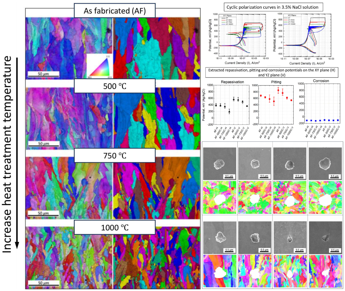
EBSD-IPF and grain images, as illustrated in Figure 3, with a resolution scale of 50 microns, enables the analysis of grain orientation in 316L stainless steel samples through a color-coded scheme based on crystal lattice orientation. The XY cross-section of the columnar grain exhibits an equiaxed feature, which remains unchanged after heat treatment (figure not shown). In the as-built condition, the grain structure appears coarsest. A gradual transition occurs with increasing heat treatment temperature. The grain structure images, as shown in Figure 3 for the XZ plane, demonstrate columnar grains. This grain size variation is consistent with that observed on the XY plane, where an increase in temperature correlates with a transformation from coarse to finer grains.
The contour pole figure (PF) collected on XZ-planes (parallel to the build direction) measures the texture strength for the three families of planes of FCC on {001}, {110}, and {111}, as shown in Figure 4. In the AF condition, an as-built texture with {101} plane orientation parallel to the build direction is developed. However, the texture begins to diminish at AF+aged 750°C and AF+aged 1000°C. The maximum multiple of uniform density (MUD) is 8.448 in the AF condition. As the heat treatment temperature increases, the MUD gradually decreases to 8.159, 6.223, and 4.287, respectively, when aged at 500°C, 750°C, and 1000°C. It is worth noting that a fully equiaxed grain structure has a MUD of around 1. Thus, the as-built {101} texture gradually diminishes with increasing heat treatment temperature.
The TEM images shown in Figure 5 demonstrate the existence of high dislocation networks, which were significantly higher than traditionally wrought samples. This is attributed to the substantial residual stresses induced by the rapid cooling phase of the LPBF process [19]. As the temperature increases, the density of dislocation networks reduces. Notably, the dislocation networks almost disappear for the AF+aged 1000°C sample. The nanometer-sized inclusions observed in AF samples were almost negligible for the AF+aged 1000°C sample. This result contrasts with [20], where inclusions were reported to be coarsened with an increase in temperature.
3.1.2. Electrochemical Analysis
The cyclic polarization of as-printed and heat-treated steels in 3.5% NaCl solution are shown in Figure 6. The repassivation potential (Erp) signifies the capability to halt the pit's growth rate, while the pit potential (Ep) is the minimum potential at which the material inclines toward pitting corrosion [21]. Beyond this potential, additional voids within the pit will initiate and enlarge. The local corrosion rate is indicated by the amount of hysteresis, or, to put it another way, by the difference between Ep and Erp. Considering that the area of the hysteresis loop of the sample annealed at 750°C is the lowest, it can be said that the possibility of pitting corrosion in this sample is less than the others. As it can be seen from Figure 6c, although there is no noticeable variation in corrosion potential for all samples (-112 mV), the corrosion rate of LPBF-XZ plane (22.68 × 10⁻⁹ A) is around two times the XY (12.26 × 10⁻⁹ A). The rationale behind this observation is the diminutive gain size characteristic of the XY plane microstructure. In addition to Mo, the high diffusion rate of Cr along the grain boundary could promote the growth and repair of a high-resistance oxide layer rich in chromium (III) oxide.
The fluctuation on the polarization curves in Figure 6a and b indicates the occurrence of metastable pitting, which is more prominent in the XZ plane (vertical plane). Frankel et al. [21] claim that the protective passive coating breaks down during the rate-controlling pitting stage. An initiated pit may propagate during pitting for a brief period of time before "dying" or it may propagate virtually endlessly (stable pitting) [22].
The pitting potentials dropped with heat treatment, and with increasing the heat treatment temperature, these values even dropped further. This reduction is more prominent for LPBF-XZ. The as-printed sample and the sample annealed at 500°C on the XZ plane demonstrated a higher pitting potential than the horizontal one (XY plane). It was found that the repassivation potential showed a similar trend to the pitting potential. This value for the LPBF-XY and XZ samples are 397.1 and 564.3 mV, respectively. It is evident that the average repassivation potential in the horizontal XY plane is lower than in the vertical XZ plane and this value in both planes decreases proportionately with heat treatment. One noteworthy observation is that, after repassivation, the corrosion rate in the XY plane is significantly lower than that of the XZ plane (Fig. 8a). That is to say, the repassive ability was always stronger on the XY plane.
Figure 7 shows the EIS results of horizontal and vertical plane specimens in 3.5% NaCl solution. Figure 7a and b correspond to the bode plots of the XY and XZ planes, respectively. As can be seen, the impedance for the XY plane at its highest frequency is approximately 2×10⁶ Ω.cm2, meaning that it is approximately 1.25 times greater than that of the XZ plane (1.6×10⁶ Ω.cm2). The stainless steels that have undergone heat treatments seem to have a depressed impedance, and the higher the treatment temperature, the lower the impedance.
The Nyquist and bode plot of XY sample along with the heat-treated samples at OCP, +100 mV, +200 mV, and +300 mV of anodic overpotential, are shown in Figure 7b, indicates that the application of anodic polarization causes the capacitive loop to enlarge (Nyquist plot). Generally speaking, a large semicircle in the Nyquist plot indicates that more difficulty in transferring electrons from the substrate to the solution, and the loop's high capacitance suggests a relationship between the formation of the passive oxide layer and the charging of the electric double layer [23]. Due to this phenomenon, impedance increases significantly at 10-3 frequency, resulting in the following sequence of impedance values: OCP < OCP +100mV < OCP +200mV < OCP +300mV. Similarly, the XZ plane exhibited a comparable pattern.
In order to supplement the qualitative analysis, impedance parameters can be obtained through an equivalent circuit analysis, as illustrated in Figure 7c. In such a circuit, Rs stands for the electrolyte resistance. The double-layer capacitance and charge transfer are denoted by CPE and Rct, respectively. An additional factor to take into account is that the mass transfer impedance, also known as the Warburg impedance, manifests as a line at low frequencies on the Nyquist diagram and can play a substantial role in the total internal resistance [23,24]. As depicted in Figure 7d, as the potential rises above the OCP, there is a notable increase in charge transfer resistance across all samples. This indicates a deceleration in the kinetics of the electrochemical process. As can be seen, the resistance of the double layer in the XY plane is higher than XZ, which can be a confirmation of the low corrosion rate in this plane. It is evident that when the treatment temperature rises, the double layer's resistance first achieves its maximum at 750°C before beginning to decline. When the potential rises in relation to OCP, this increase becomes more apparent such that at 300 mV above OCP, XY and XZ samples annealed at 750°C have a resistance of 10.28×10⁶ Ω and 7.32×10⁶ Ω, respectively. Following 750°C, samples annealed at 500°C and 1000°C have the highest passive layer resistance. It should be noted that raising the overpotential above 300 mV in relation to OCP resulted in a rather discernible change in the double layer's resistance.
3.2. Discussion:
The key microstructural features observed in the AF samples during heat treatment are the refined grain structures and reduced dislocation densities with increasing heat treatment temperature (refer to Figure 2, Figure 3 and Figure 5). The visibility of melt pool boundaries up to 500°C and their subsequent fading at higher temperatures (750°C and 1000°C) is accompanied by drastically reduced dislocation densities (Figure 5), indicating a higher dislocation mobility above 500°C facilitating a transition in the microstructural characteristics. The reduction in grain size with increasing heat treatment temperature contradicts the grain growth around the same temperature range as reported in [18,25], possibly due to differences in L-PBF parameters and/or heat treatment conditions, thus highlights the complexity of predicting microstructural evolution in additively manufactured metals. At all the different heat treatment temperatures, the grain shape remains mostly columnar and elongated along the build direction, regardless of the reduced grain size and increased number of grains.
The corrosion resistance of AF+aged 316L demonstrated a decrease in repassivation and pitting potentials with increased treatment temperature, suggesting deterioration in its resistance to pitting corrosion. Additionally, the as-print texture leads to an anisotropic corrosion resistance. In the as-print condition, the XY plane demonstrates significantly lower pitting and repassivation potentials compared to the XZ plane but its ability to repassive is stronger than XZ plane. The superior pitting resistance of the XZ plane over the XY plane gradually weakens with the heat treatment process. At 750°C and 1000°C, the pitting potential on the XY and XZ planes is very close. Further comparing between the vertical (XZ) and horizontal (XY) planes leads to seemingly controversial results. The corrosion rates measured at the OCP are 2-3 times higher on the XZ plane compared to XY one, where a lower corrosion rate of the XY plane indicates better corrosion resistance. At repassivation, the XY plane demonstrates a superior reduction in corrosion rate, indicating a more effective repassivation process compared to the XZ plane, despite a lower repassivation potential on the XY plane. Repassivation on the XZ plane was incomplete since, during reverse scanning, curves did not ever meet the anodic part. The EIS results further support the difference in passive film resistance between the XY and XZ planes, in that a higher charge transfer resistance (Rct) is found for the XY plane at all elevated potentials. However, the dependence of charge transfer resistance (Rct) on the heat treatment temperature is unclear. At OCP+300 mV, the AF+750 °C aged condition possesses the highest Rct, followed by AF, AF+500°C, and 1000°C aged conditions, whereas a different sequence is found at other elevated potentials.
Due to the columnar-shaped grains, the XY plane possesses a higher number of grains per unit area compared to the XZ plane, resulting in a larger area of grain boundaries. Grain boundaries may play a dual role. On one hand, they are defective sites with an increased susceptibility to pitting [27,28]. On the other hand, they can act as fast diffusion channels, similar to the role played by sub-grain dislocation cellular structures. Previous studies have highlighted the beneficial effect of sub-grain dislocation cellular/columnar structures [6,29] in the anti-corrosion resistance of 316L. Due to the general 〈100〉 orientation of the sub-grain boundaries and the strong texture developed in the as-built condition [30,31], the dislocation sub-grains intersect with the XY and XZ planes predominately in the form of cellular structures. Thus, the higher pitting potential of the XZ plane should be attributed to the smaller area of high-angle grain boundaries. Similarly, the increased number of grain sizes and thus high-angle grain boundaries with increasing annealing temperature are responsible for the reduced pitting potentials. The reduced density of dislocation sub-grains also contributes to the reduced pitting and repassivation resistance with increasing heat treatment temperatures.
On the other hand, both the high-angle grain boundaries and dislocation networks serve as fast diffusion channels, likely facilitating the formation of a more stable and protective passive film and its repair from pitting. As a result, the XY plane possesses a higher charge transfer resistance, indicating a stronger passive film compared to the XZ plane. Its repassivation is also more effective compared to the XZ plane. The controversy (higher pitting and repassivation potential yet higher repassivation current density of the XZ over the XY plane) may relate to the complicated roles played by both the high-angle grain boundaries and dislocation networks, as discussed above.
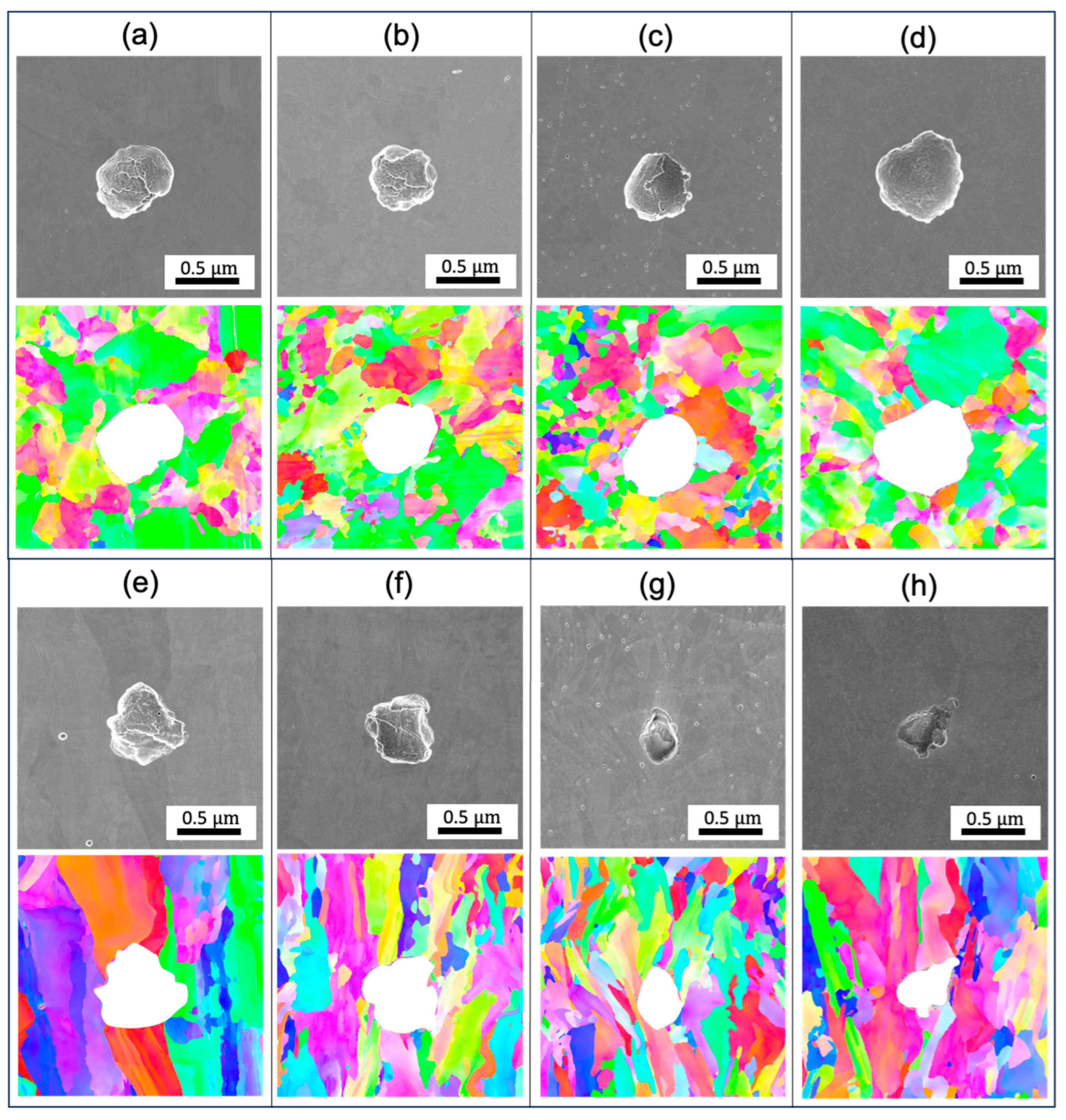
Figure 8 shows the pitting morphology of the AF and AF+aged 316L stainless steels post-cyclic polarization test. Notably, the pits exhibit a predominantly spherical shape across all examined specimens on the XY plane. The pits on the XZ plane shows a more irregular shape. The inhomogeneity may be related to the grain orientation-dependent corrosion resistance. With thermal treatment at an increasingly higher temperature, the pits on the XZ planes become narrower in the opening and deeper in penetration depth, confirming the weakened corrosion resistance. Additionally, it was not observed that pitting preferentially grows along the grain boundary or the melt pool boundaries. This could be related to negligible segregation near the GBs.
Previous studies [20,32,33] have highlighted the presence of nanoscale inclusions within 316L produced by L-PBF. Consistent with those reports, no microscale inclusions or precipitates are found in the as-printed or heat-treated state. These observations suggest that micro-inclusions were not the principal factors initiating pitting. Similar to previous reports [20,34,35], nanoparticles have been found in the AF condition. Saeidi et al. [35] observed a reduction in silicon and chromium concentrations surrounding circular nano-inclusions, suggesting that the creation of these inclusions involved the absorption of these elements from adjacent regions. However, determining whether pitting corrosion initiated at the inclusion sites was challenging through post-examination observations [36]. It has been reported that the presence of nanoscale inclusions is less likely to contribute detrimentally to corrosion performance [16,35,37].
In this work, fine grains with different orientations grow from the original larger columnar grains, yet the new grains still exhibit a columnar shape, differing from the typical equiaxed grain structure observed after static recrystallization. Sub-grain dislocation networks also contribute to the formation of high-angle grain boundaries, facilitating enhanced atom diffusion and dislocation mobility. In future work, we aim to further understand the mechanism of grain size reduction during heat treatment. Furthermore, the microstructural variations and the effects of heat treatment on the corrosion fatigue properties of 316L will also be the focus of our study in the near future.
4. Conclusion
In this work, the effects of post-fabrication heat treatment on 316L fabricated by L-PBF on the aspects of microstructural features and corrosion performance, particularly considering treatment at 500°C, 750°C, and 1000°C were evaluated. The main findings are summarized as follows:
- The microstructures are significantly altered during the heat treatment. The changes include diminished melt pool boundaries and dislocation cellular structures, along with reduced grain size, with increasing treatment temperatures. The grains remain the elongated and columnar shape during the process.
- A deterioration in corrosion resistance with increased annealing temperature, evidenced by reduced pitting and repassivation potentials.
- Anisotropic corrosion resistance is also observed. The vertical plane (parallel to the build direction) exhibits a higher pitting and repassivation potential, yet a higher current density is observed post-repassivation. The degree of anisotropy gradually diminishes with increasing treatment temperature.
- The increased grain boundaries and reduced dislocation cell densities are attributed to for the different corrosion performance after heat treatment.
The main findings of this research contribute to a deeper understanding of the post fabrication processing-structure-property relationships in 316L stainless steel fabricated via L-PBF, pointing towards the importance of optimizing manufacturing and heat treatment parameters to enhance material performance in corrosive environments.
Author Contributions
validation, formal analysis, investigation, data curation, writing - original draft, writing – review & editing, visualization, K.S.; formal analysis, investigation, data curation, writing - original draft, writing – review & editing, M.N.; conceptualization, investigation, resources, writing – review & editing, supervision, J.S.; conceptualization, methodology, resources, writing – review & editing, supervision, project administration, funding acquisition, Y.F.
Funding
The authors gratefully acknowledge the National Science Foundation (Award No. 2139383) and (Award No. 2245107), and Office of Naval Research (Award No. N00014-21-1-2800) for providing the financial support.
Acknowledgments
This work utilized the Nanoscale Characterization and Fabrication Laboratory, a part of the National Nanotechnology Coordinated Infrastructure (NNCI), funded by NSF (ECCS 1542100 and ECCS 2025151).
References
- M. Sumita, T. Hanawa, and S. Teoh, "Development of nitrogen-containing nickel-free austenitic stainless steels for metallic biomaterials," Materials Science and Engineering: C, vol. 24, no. 6-8, pp. 753-760, 2004. [CrossRef]
- M. Imbaby, K. Jiang, and I. Chang, "Net shape fabrication of stainless-steel micro machine components from metallic powder," Journal of Micromechanics and Microengineering, vol. 18, no. 11, p. 115018, 2008. [CrossRef]
- J.-P. Choi et al., "Densification behavior of 316L stainless steel parts fabricated by selective laser melting by variation in laser energy density," Materials Transactions, vol. 57, no. 11, pp. 1952-1959, 2016. [CrossRef]
- O. O. Salman, A. Funk, A. Waske, J. Eckert, and S. Scudino, "Additive manufacturing of a 316L steel matrix composite reinforced with CeO2 particles: process optimization by adjusting the laser scanning speed," Technologies, vol. 6, no. 1, p. 25, 2018. [CrossRef]
- N. Kurgan and R. Varol, "Mechanical properties of P/M 316L stainless steel materials," Powder Technology, vol. 201, no. 3, pp. 242-247, 2010. [CrossRef]
- B. Gnanasekaran, J. Song, V. Vasudevan, and Y. Fu, "Corrosion fatigue characteristics of 316L stainless steel fabricated by laser powder bed fusion," Metals, vol. 11, no. 7, p. 1046, 2021. [CrossRef]
- J. P. Pragana et al., "Influence of processing parameters on the density of 316L stainless steel parts manufactured through laser powder bed fusion," Proceedings of the Institution of Mechanical Engineers, Part B: Journal of Engineering Manufacture, vol. 234, no. 9, pp. 1246-1257, 2020. [CrossRef]
- S. Ziri, A. Hor, and C. Mabru, "Combined effect of powder properties and process parameters on the density of 316L stainless steel obtained by laser powder bed fusion," The International Journal of Advanced Manufacturing Technology, vol. 120, no. 9, pp. 6187-6204, 2022. [CrossRef]
- G. Huang, K. Wei, J. Deng, M. Liu, and X. Zeng, "High-power laser powder bed fusion of 316L stainless steel: Defects, microstructure, and mechanical properties," Journal of Manufacturing Processes, vol. 83, pp. 235-245, 2022.
- S. Piazza, B. Merrigan, D. P. Dowling, and M. Celikin, "The effects of geometry and laser power on the porosity and melt pool formation in additively manufactured 316L stainless steel," The International Journal of Advanced Manufacturing Technology, vol. 111, pp. 1457-1470, 2020. [CrossRef]
- G. Sander et al., "On the corrosion and metastable pitting characteristics of 316L stainless steel produced by selective laser melting," Journal of the electrochemical society, vol. 164, no. 6, p. C250, 2017. [CrossRef]
- Y. Sun, A. Moroz, and K. Alrbaey, "Sliding wear characteristics and corrosion behaviour of selective laser melted 316L stainless steel," Journal of materials engineering and performance, vol. 23, pp. 518-526, 2014. [CrossRef]
- R. F. Schaller, J. M. Taylor, J. Rodelas, and E. J. Schindelholz, "Corrosion properties of powder bed fusion additively manufactured 17-4 PH stainless steel," Corrosion, vol. 73, no. 7, pp. 796-807, 2017. [CrossRef]
- K. Geenen, A. Röttger, and W. Theisen, "Corrosion behavior of 316L austenitic steel processed by selective laser melting, hot-isostatic pressing, and casting," Materials and Corrosion, vol. 68, no. 7, pp. 764-775, 2017.
- J. Song, K. Sangoi, M. Nadimi, and Y. Fu, "Remarkably enhanced corrosion performance of 316 L stainless steel via laser powder bed fusion thin-layer deposition," Materials Today Communications, vol. 38, p. 107690, 2024. [CrossRef]
- M. Laleh, A. E. Hughes, W. Xu, P. Cizek, and M. Y. Tan, "Unanticipated drastic decline in pitting corrosion resistance of additively manufactured 316L stainless steel after high-temperature post-processing," Corrosion Science, vol. 165, p. 108412, 2020. [CrossRef]
- L. Jinhui, L. Ruidi, Z. Wenxian, F. Liding, and Y. Huashan, "Study on formation of surface and microstructure of stainless steel part produced by selective laser melting," Materials Science and Technology, vol. 26, no. 10, pp. 1259-1264, 2010. [CrossRef]
- C. Zhou et al., "Improvement of corrosion resistance of SS316L manufactured by selective laser melting through subcritical annealing," Corrosion Science, vol. 164, p. 108353, 2020. [CrossRef]
- Y. Liu, Y. Yang, and D. Wang, "A study on the residual stress during selective laser melting (SLM) of metallic powder," The International Journal of Advanced Manufacturing Technology, vol. 87, pp. 647-656, 2016. [CrossRef]
- Q. Chao et al., "On the enhanced corrosion resistance of a selective laser melted austenitic stainless steel," Scripta Materialia, vol. 141, pp. 94-98, 2017. [CrossRef]
- G. S. Frankel, "Pitting Corrosion of Metals A Review of the Critical Factors," Journal of The Electrochemical Society, vol. 145, pp. 2186-2198, 1998. [CrossRef]
- J. A. Khamaj, "Cyclic polarization analysis of corrosion behavior of ceramic coating on 6061 Al/SiCp composite for marine applications," Protection of Metals and Physical Chemistry of Surfaces, vol. 52, no. 5, pp. 886-893, 2016/09/01 2016. [CrossRef]
- K. Jüttner, "Electrochemical impedance spectroscopy (EIS) of corrosion processes on inhomogeneous surfaces," Electrochimica Acta, vol. 35, no. 10, pp. 1501-1508, 1990/10/01/ 1990. [CrossRef]
- J. Pang, A. Briceno, and S. Chander, "A Study of Pyrite/Solution Interface by Impedance Spectroscopy," Journal of The Electrochemical Society, vol. 137, no. 11, p. 3447, 1990/11/01 1990. [CrossRef]
- O. Salman, C. Gammer, A. K. Chaubey, J. Eckert, and S. Scudino, "Effect of heat treatment on microstructure and mechanical properties of 316L steel synthesized by selective laser melting," Materials Science and Engineering: A, vol. 748, pp. 205-212, 2019. [CrossRef]
- F. H. A. Rollett, G.S. Rohrer, M. Hatherly, Recrystallization and Related Annealing Phenomena, Second edition ed. Kidlington, Oxford OX5 1GB, UK: Elsevier Ltd, 2004.
- M. Terada, M. Saiki, I. Costa, and A. F. Padilha, "Microstructure and intergranular corrosion of the austenitic stainless steel 1.4970," Journal of Nuclear Materials, vol. 358, no. 1, pp. 40-46, 2006. [CrossRef]
- M. Terada, D. Escriba, I. Costa, E. Materna-Morris, and A. F. Padilha, "Investigation on the intergranular corrosion resistance of the AISI 316L (N) stainless steel after long time creep testing at 600 C," Materials Characterization, vol. 59, no. 6, pp. 663-668, 2008. [CrossRef]
- C. Zhou et al., "Enhanced corrosion resistance of additively manufactured 316L stainless steel after heat treatment," Journal of The Electrochemical Society, vol. 167, no. 14, p. 141504, 2020. [CrossRef]
- M. L. Montero-Sistiaga, M. Godino-Martinez, K. Boschmans, J.-P. Kruth, J. Van Humbeeck, and K. Vanmeensel, "Microstructure evolution of 316L produced by HP-SLM (high power selective laser melting)," Additive Manufacturing, vol. 23, pp. 402-410, 2018. [CrossRef]
- J. M. Jeon et al., "Effects of microstructure and internal defects on mechanical anisotropy and asymmetry of selective laser-melted 316L austenitic stainless steel," Materials Science and Engineering: A, vol. 763, p. 138152, 2019. [CrossRef]
- D. Kong et al., "Heat treatment effect on the microstructure and corrosion behavior of 316L stainless steel fabricated by selective laser melting for proton exchange membrane fuel cells," Electrochimica Acta, vol. 276, pp. 293-303, 2018. [CrossRef]
- X. Ni et al., "Corrosion behavior of 316L stainless steel fabricated by selective laser melting under different scanning speeds," Journal of materials engineering and performance, vol. 27, pp. 3667-3677, 2018. [CrossRef]
- S. Gorsse, C. Hutchinson, M. Gouné, and R. Banerjee, "Additive manufacturing of metals: a brief review of the characteristic microstructures and properties of steels, Ti-6Al-4V and high-entropy alloys," Science and Technology of advanced MaTerialS, vol. 18, no. 1, pp. 584-610, 2017.
- K. Saeidi, X. Gao, Y. Zhong, and Z. J. Shen, "Hardened austenite steel with columnar sub-grain structure formed by laser melting," Materials Science and Engineering: A, vol. 625, pp. 221-229, 2015. [CrossRef]
- R. F. Schaller, A. Mishra, J. M. Rodelas, J. M. Taylor, and E. J. Schindelholz, "The role of microstructure and surface finish on the corrosion of selective laser melted 304L," Journal of the electrochemical society, vol. 165, no. 5, p. C234, 2018. [CrossRef]
- M. Lodhi, A. Iams, E. Sikora, and T. Palmer, "Microstructural features contributing to macroscopic corrosion: The role of oxide inclusions on the corrosion properties of additively manufactured 316L stainless steel," Corrosion Science, vol. 203, p. 110354, 2022. [CrossRef]
- J. Suryawanshi, K. Prashanth, and U. Ramamurty, "Mechanical behavior of selective laser melted 316L stainless steel," Materials Science and Engineering: A, vol. 696, pp. 113-121, 2017. [CrossRef]
Figure 1.
SEM images of the (a) AF and (b)-(e) AF+aged samples (XZ plane) at different heat treatment temperatures.
Figure 1.
SEM images of the (a) AF and (b)-(e) AF+aged samples (XZ plane) at different heat treatment temperatures.
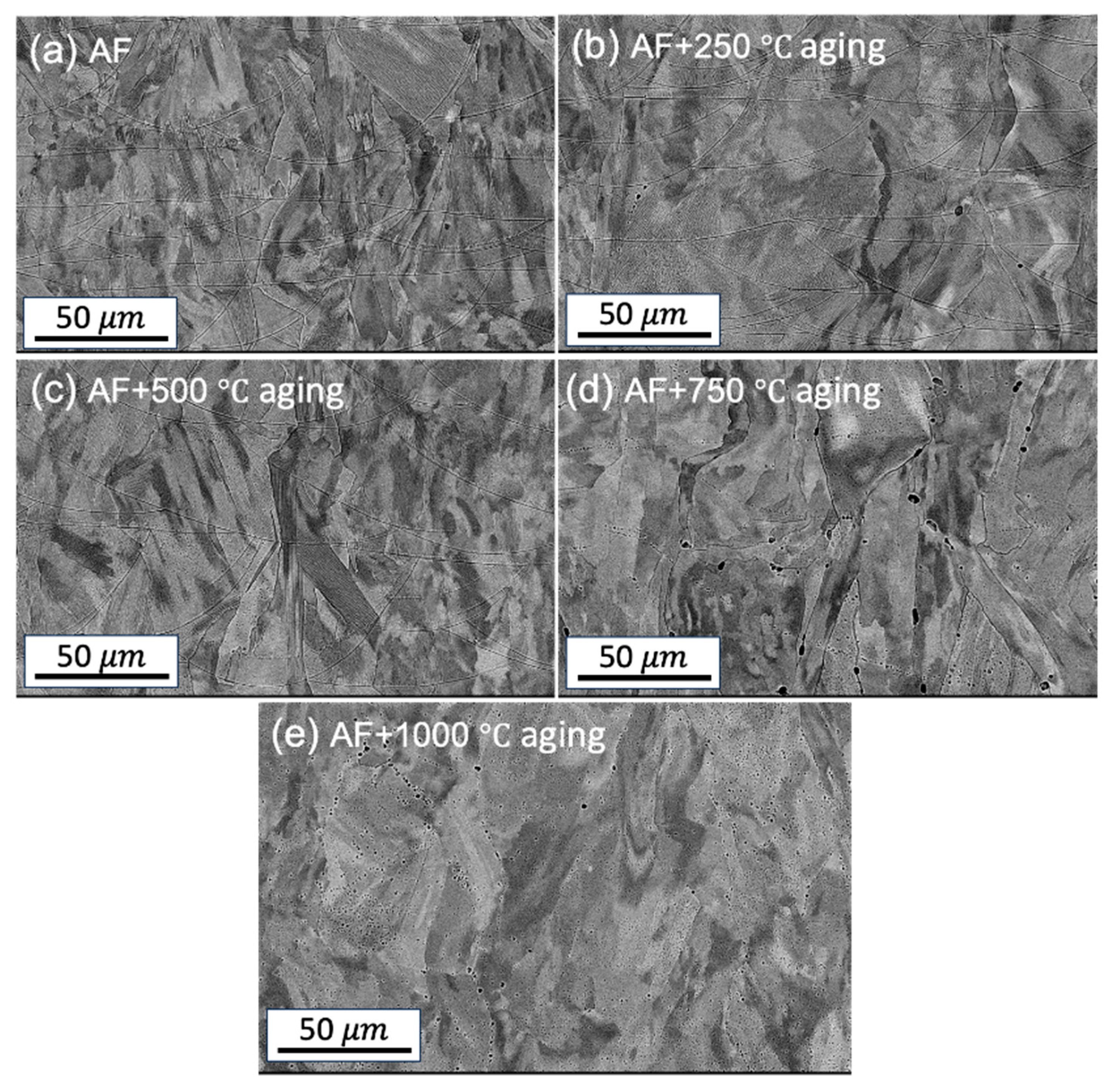
Figure 2.
Grain size comparison of the AF and AF+aged samples at different heat treatment temperatures and for XY and XZ plane.
Figure 2.
Grain size comparison of the AF and AF+aged samples at different heat treatment temperatures and for XY and XZ plane.
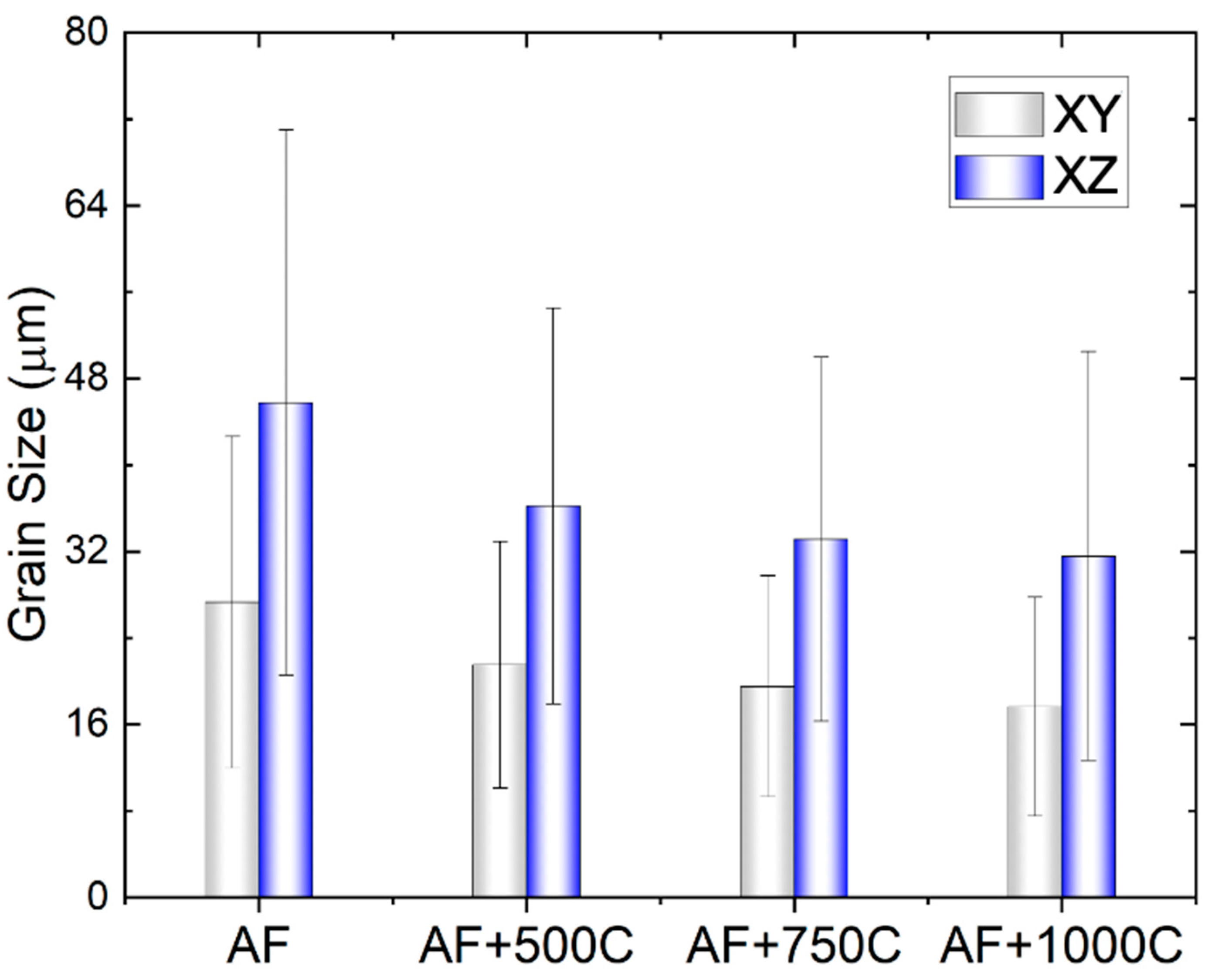
Figure 3.
EBSD-IPF images (left) and grain structures (right) of the AF and AF+aged samples at different heat treatment temperatures as shown in the subfigures (a)-(d).
Figure 3.
EBSD-IPF images (left) and grain structures (right) of the AF and AF+aged samples at different heat treatment temperatures as shown in the subfigures (a)-(d).
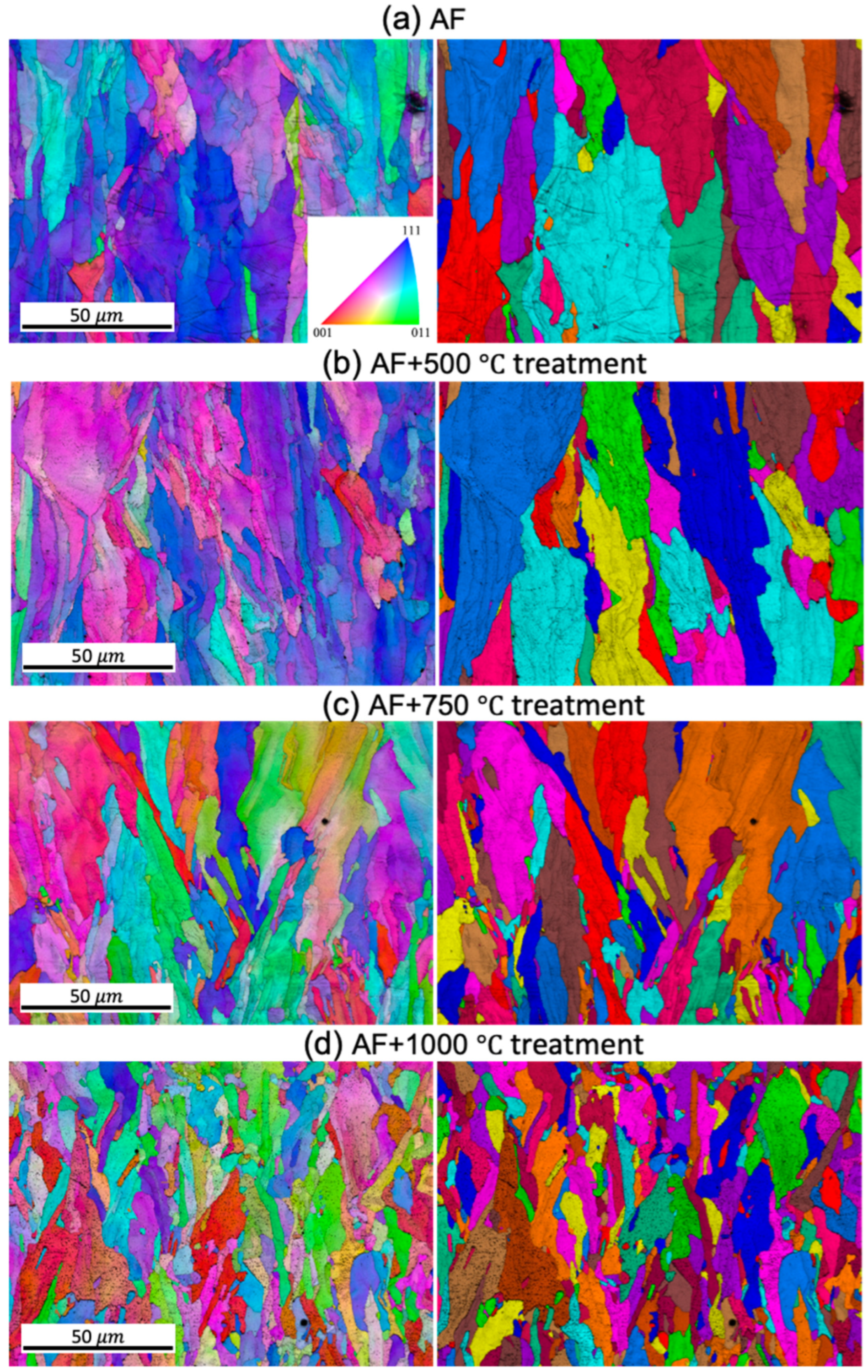
Figure 4.
Pole-figure images of the AF and AF+heat treated samples on the XZ plane at different heat treatment temperatures as shown in the subfigures (a)-(d).
Figure 4.
Pole-figure images of the AF and AF+heat treated samples on the XZ plane at different heat treatment temperatures as shown in the subfigures (a)-(d).
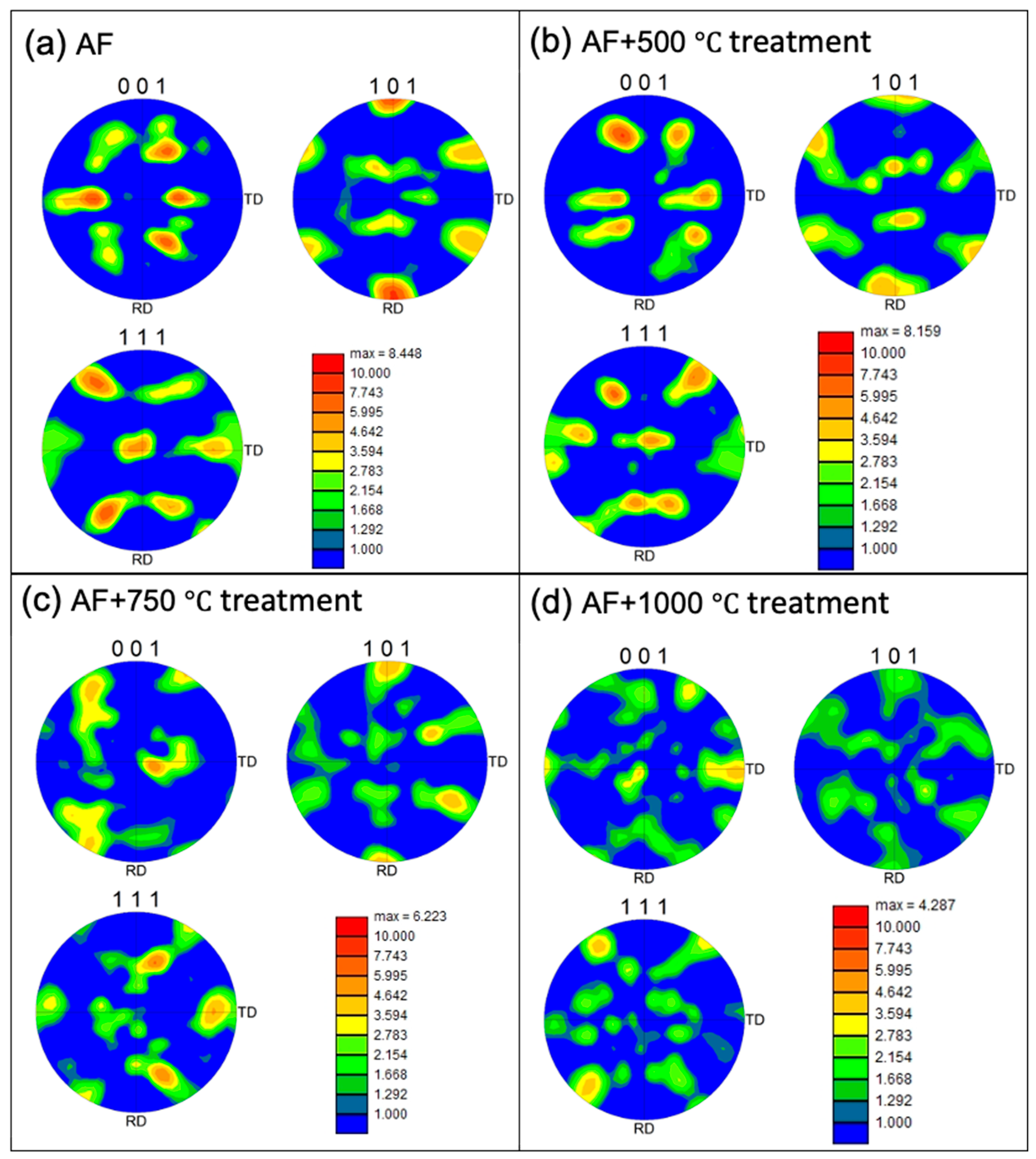
Figure 5.
TEM images of the AF and AF+aged samples at different heat treatment temperatures as shown in the subfigures (a)-(d).
Figure 5.
TEM images of the AF and AF+aged samples at different heat treatment temperatures as shown in the subfigures (a)-(d).
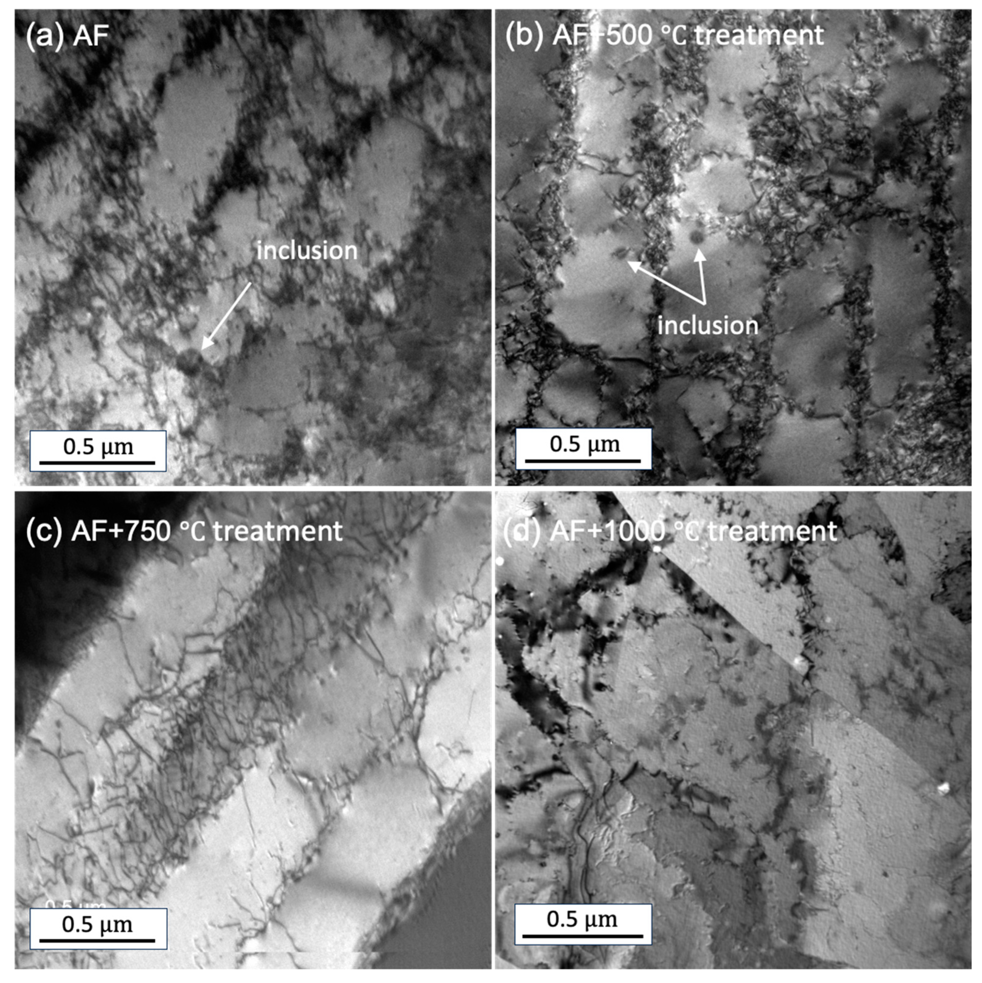
Figure 6.
Cyclic polarization for plane (a) XY and (b) XZ shown, and (c) repassivation potential, pitting potential, corrosion potential extracted from the cyclic polarization curves for AF and AF+aged samples.
Figure 6.
Cyclic polarization for plane (a) XY and (b) XZ shown, and (c) repassivation potential, pitting potential, corrosion potential extracted from the cyclic polarization curves for AF and AF+aged samples.
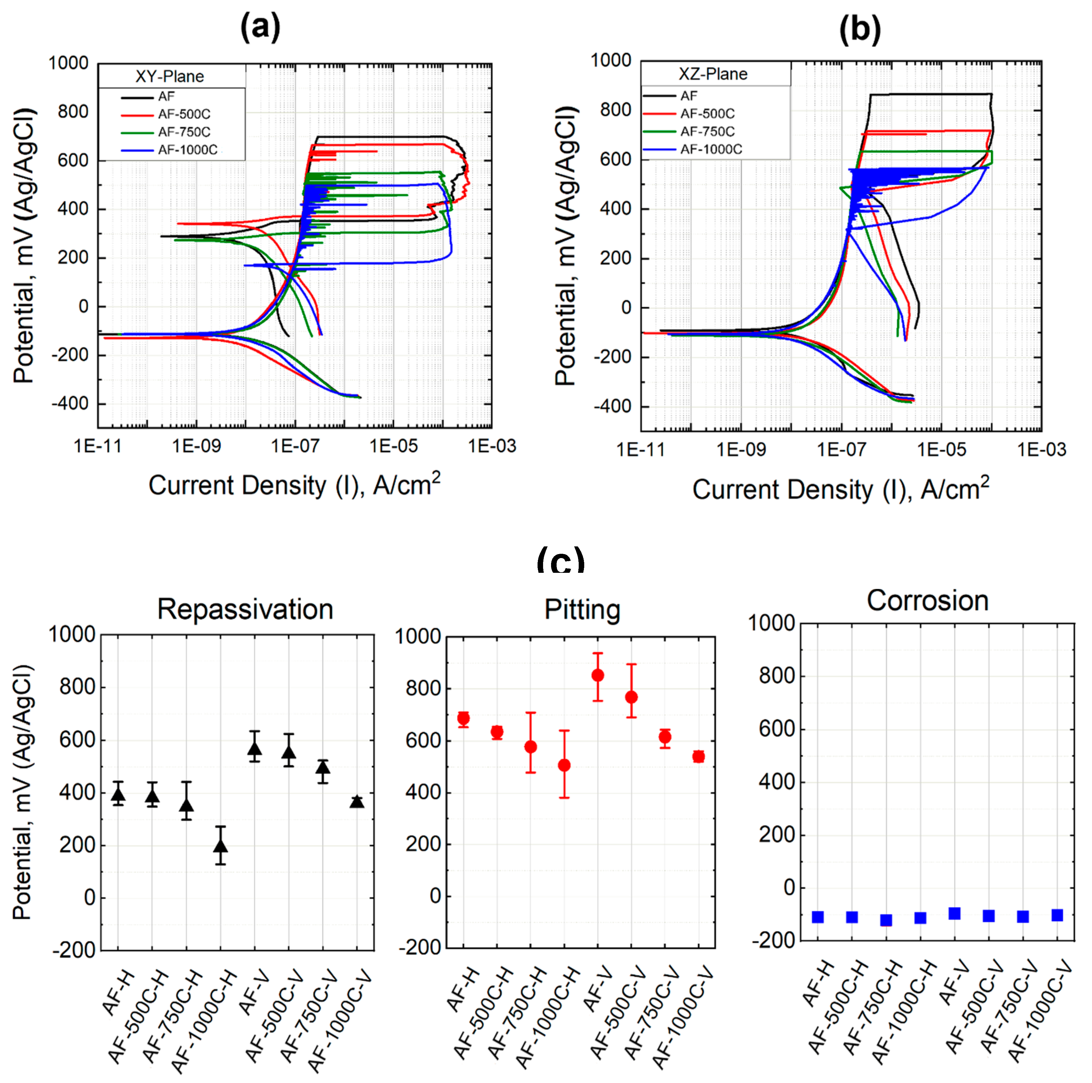
Figure 7.
EIS results of the AF and AF+aged samples: (a) EIS-bode plots of the XY and XZ plane, (b) Bode and Nyquist plots of the XY plane, (c) equivalent circuit for fitting the EIS results, and (d) extracted charge transfer resistance (Rct) from the fitting to equivalent circuit.
Figure 7.
EIS results of the AF and AF+aged samples: (a) EIS-bode plots of the XY and XZ plane, (b) Bode and Nyquist plots of the XY plane, (c) equivalent circuit for fitting the EIS results, and (d) extracted charge transfer resistance (Rct) from the fitting to equivalent circuit.
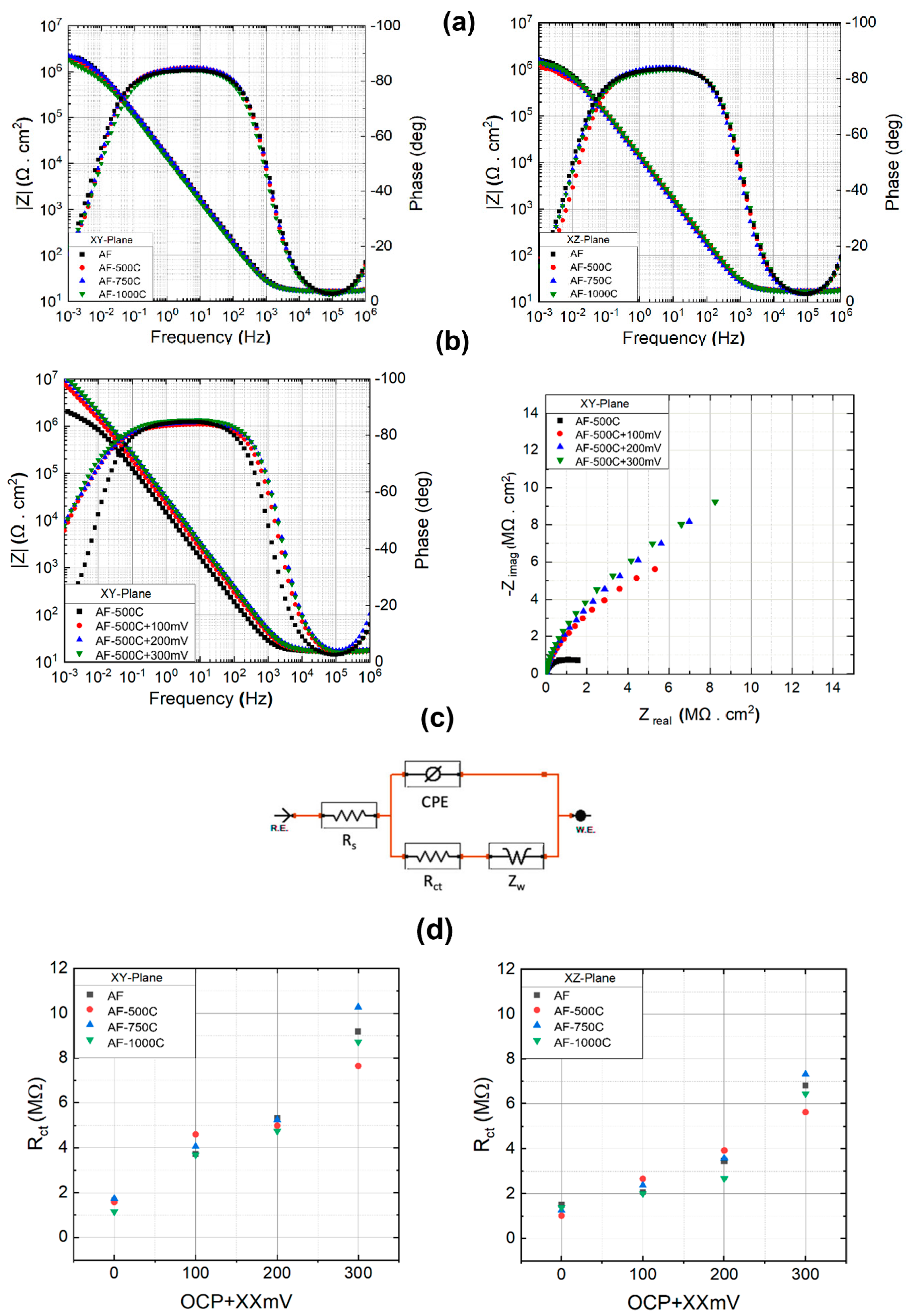
Figure 8.
SEM, EBSD and IPF correlation figures of the AF and AF+aged pit samples at different heat treatment temperatures as shown in the subfigures: (a)-(d) correspond to the AF, AF+500 °C, AF+750 °C, AF+1000 °C on the XY plane; (e)-(h) correspond to the AF, AF+500 °C, AF+750 °C, AF+1000 °C on the XZ plane.
Disclaimer/Publisher’s Note: The statements, opinions and data contained in all publications are solely those of the individual author(s) and contributor(s) and not of MDPI and/or the editor(s). MDPI and/or the editor(s) disclaim responsibility for any injury to people or property resulting from any ideas, methods, instructions or products referred to in the content. |
© 2024 by the authors. Licensee MDPI, Basel, Switzerland. This article is an open access article distributed under the terms and conditions of the Creative Commons Attribution (CC BY) license (http://creativecommons.org/licenses/by/4.0/).
Copyright: This open access article is published under a Creative Commons CC BY 4.0 license, which permit the free download, distribution, and reuse, provided that the author and preprint are cited in any reuse.


