
Submitted:
18 November 2024
Posted:
20 November 2024
You are already at the latest version
Abstract
This paper presents a detailed mathematical procedure for implementing a three-phase induction motor model. Induction motors are crucial components in electric power systems. Therefore, several investigations have been conducted on the three-phase motor model. However, the mathematical representations for model development are complex due to nonlinearity and complicated structure. In this case, a composite load model is used to provide a block diagram based on the fifth-order analytical method in polar coordinates to calculate the transient and subtransient responses of a three-phase motor. Specifically, the behavior of a three-phase deep-slot squirrel cage motor is represented using parameters to describe its response from start-up to the voltage sag. Simulation was used to calculate the responses of the electromechanical variables after disturbances, in order to better understand the dynamic behavior of motor loads in voltage stability in electrical systems. The results were compared with those in the literature to verify the performance of the model.
Keywords:
Induction motor
; Voltage stability
; Compound Load Model WECC
1. Introduction
The blocking of three-phase induction motors during voltage dips in the network contributes significantly to the problem of slow voltage recovery stability (FIDVR) [1,2,3]. As three-phase induction motors account for 70% of electricity consumption [4], an accurate load model is essential to understand the dynamic behaviour of motor loads in power systems and to perform preventive analysis of network stability [5,6].
Researchers such as [7,8,9] have advanced the industrial practice of load modeling from the simple static model to a combination of static and dynamic load models (ZIP load plus three-phase induction motor model), and the more recent WECC (Western Electricity Coordinating Council) composite load model [7,10]. The research [11] highlights the WECC model as the most popular and accurate composite load model because it includes a variety of three-phase motors, single-phase motors and electronic components, giving it the flexibility to capture specific characteristics at different loads. Despite advances in the accuracy of the WECC composite load model in recent years [12], further work is needed to refine it to more accurately represent the behaviour of end-use loads in power system transient stability analysis [10].
The WECC model is available in computational tools for the development of electromechanical transient studies such as GE PSLF, Power World Simulator and PSSE. [10]. This model includes three types of three-phase induction motors and represents the characteristics of a group of motors for each type [13]. However, the technical methods and mathematical representations for developing the model of these loads are not publicly available from simulation programs [10]. Limiting the development of the induction motor model to anticipate critical events, optimize resource utilization and reduce losses in a specific electrical network [5].
A block diagram derived from the three-phase motor model provided by WECC [14,15], has been developed for transient and subtransient analysis of induction motors. This diagram considers the stator and rotor circuit transients along with the rotor speed transient [15]. Due to the nonlinearity of the structure, it is difficult to directly apply analytical approaches to calculate the partial derivatives [16]. This paper presents a mathematical procedure for implementing the three-phase induction motor model proposed by WECC and calculating its transient and subtransient responses.
The mathematical model was implemented in Simulink MATLAB to Analyse the dynamic responses of a three-phase induction motor. The verification was performed using parameters of a three-phase squirrel cage induction motor with deep slots, which, according to [17], is the most widely used motor in the industry due to its simple design and ease of maintenance. The verification of the model under voltage disturbances was compared with results on motors obtained from the literature after voltage drop disturbances.
The first section of the paper presents the mathematical procedure for the implementation of the three-phase induction motor modeling as a WECC load, addressing the necessary adjustments to ensure its representation. Section two presents the results of simulations, with graphs, and analyses that illustrate the motor dynamics at start-up and in the face of voltage drop disturbances. Finally, section four presents the conclusions of the model implementation and simulation results, addressing the verification of the proposed model. .
2. Materials and Methods
Various studies have examined the mathematical model of induction motors as electrical system loads [18,19,20]. In [15], a third-order model based on the orthogonal system was used to calculate the transient responses of three-phase induction motors. Similarly, [19] used the same model but presented the results in polar coordinates, expressing the magnitude and phase angle. Although these investigations represent the induction motor model, they do not follow the WECC (refer to Figure 1) methodology like [10,21,22] used a fifth-order system to model the three-phase induction motor (refer to Figure 2)
The model is used to perform electromechanical transient analysis on a double-squirrel-cage motor (type C motor) [10], but it can also be applied to three-phase induction motors, including type A (single squirrel-cage motor), type B (deep-slotted squirrel-cage motor) [17].
2.1. Mathematical Model of the Three-Phase Induction Motor
The literature review provided a representation of the mathematical equations for modelling a three-phase induction motor as a WECC load up to fifth order. This representation includes the electromechanical behavior in its state variables [10]. The electrical part of the model is described by four state variables: the transient and subtransient Voltages of the direct and quadrature axis (, , and ). Equations 1 to 4, as described in [21], express these variables.
In the works of [19,21] the transient quadrature FEM , transient direct FEM , subtransient quadrature FEM , subtransient direct FEM , and slip feedback (Sslip) of the dynamic state of the motor are defined as inputs to the system. The direct current () and the quadrature current () are the inputs to the system [23].
Where , and represent, respectively, the synchronous, transient and subtransient inductance per unit; and are the transient and subtransient time constants of the rotor. The parameters were obtained from the motor’s equivalent circuit per unit, following the procedure described in references [4,15,24,25] using Equations 5 to 7.
According to [14], for Engine A and B, it is confirmed that = , and = 0 . In the case of the double cage design, which implies the presence of two resistances (, ) and two reactors (, ) connected in parallel. based on [4], the values of of and are determined from Equations8 and 9 [2].
Equations 5 to 9 define the following variables is the rotor resistance with respect to the stator side, is the stator reactance, represents the rotor leakage reactance with respect to the stator, is the magnetization reactance, and corresponds to the synchronous speed.
The fifth state variable is the rotor slip (), which is obtained using Equation 10 [21,22]. Here, H represents the inertia constant in seconds, as defined in [26,27]. The motor speed () is defined as 1-, according to [21]. The term represents tthe mechanical torque damping coefficient, which is adjusted based on the motor characteristic.
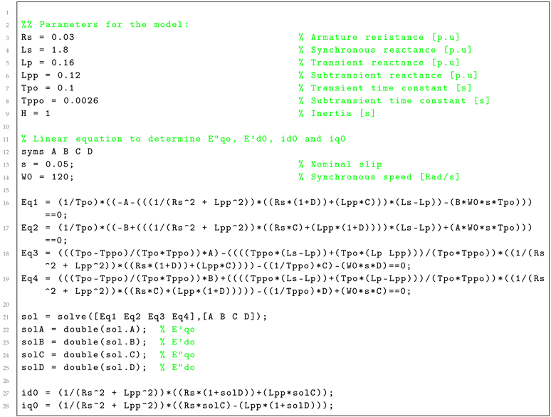
Equation 11 plots the electrical torque (), while Equation 12 calculates the initial mechanical torque () using the subtransient voltages and initial currents in the direct and quadrature axis (, , and ). These values have been determined by research [10,28] and are obtained by solving the system of equations 1 to 4, which are equal to zero. Please refer to Appendix A for further details.
Figure 2 shows that the model’s input parameters are the direct and quadrature axis currents (, ), as expressed in Equations 13 and 14 [21].
The voltages along the direct axis and quadrature axis (, )" correspond to the decomposition of the motor input voltage in terms of the d and q axes. The magnitude of the voltage is the square root of the sum of the squared sum of and [29]. According to [30], it is suggested that = 0 and is equal to the value in per unit of the voltage magnitude. Equations 15 and 16 express the active (P) and reactive (Q) per unit.
3. Results and Discussion
The block diagram in Figure 2 was created in Simulink MATLAB using the mathematical representation of a three-phase induction motor as the load for the WECC model [10,21,22]. The model can be applied to all three types of three-phase motors but used the parameters of the type B motor from [21], As shown in Table 1, to analyze one of the most widely used motors in the industry, as stated in [17].
The block diagram shown in Figure 2 was created in Simulink MATLAB using a mathematical representation of a three-phase induction motor as the load for the WECC model [15,21]. This was done to determine (, , and ), as described in Equations 1 to 4. However, the input voltage to the motor (, ), decomposed into the d and q axes represented by the orthogonal and quadrature axis voltages, must also be determined.
The voltage magnitude was calculated as the square root of the sum of the squares of and [29]. It is essential to set equal to zero and equal to one unit of the voltage magnitude to ensure an accurate value of |V| [30].
The direct and quadrature axial currents of the induction motor (, ) are determined using Equations 13 and 14, as illustrated in the block diagram in Figure 3. The parameters Rs and Lpp are provided in Table 1.
3.1. Motor Energization Simulation
A voltage of 1.0 per unit (p.u) was applied to the direct shaft voltage () one second after the start of the simulation to observe the behavior of the electromechanical variables during motor start-up. Figure 4 shows that the electrical torque at start-up reaches a maximum value of 2.48 p.u in 0.58 seconds, and that the mechanical torque has an exponential behavior that stabilizes at the same time as the electrical torque.
During start-up, the electric torque must overcome the inertia of the rotor and the load to accelerate the motor, as explained in [17]. This means that the electrical torque surpasses the mechanical torque.
3.2. Verification of the Model
To verify the implemented model, a voltage drop was applied to the motor in steady state, following the methodology described in [21]. Figure 6 shows the perturbation applied to the motor model, where ( and ) represent the direct and quadrature axis voltages. The obtained results were compared with the type B motor simulations presented in [21].
The motor speed in steady state is 0.948 p.u. When a disturbance is applied, the speed decreases to 0.933 p.u. in 0.1 seconds and then recovers linearly in 1.1 seconds, as illustrated in Figure 7.
The active power consumption is affected by the voltage drop in the motor, as demonstrated in Figure 8. The figure displays the active power results of the implemented model and those presented by Zixao Ma in [21].
Both results transiently decreased from 0.948 p.u to 0.45 p.u during the disturbance. The implemented model’s active power response had an additional second transient at 1.1 seconds, but both results were reestablished after 2.1 seconds.
Figure 9 shows the response to a reactive power disturbance of the implemented model and the results presented by Zixao Ma in [21]. The power was at a steady state of 0.68 p.u. When the perturbation was applied, the power transiently decreased to -0.7 p.u. At 1.1 seconds, during the reset, another transient occurred. The response of the implemented model had a magnitude of 1.2 p.u, while in [21] it was 0.77 p.u. Both responses returned to steady state in 1.2 seconds.
The active and reactive power results exhibit a similar behavior to those in [21] . This section includes an analysis of the motor’s electromechanical variables, such as speed, mechanical torque, and electrical torque, which depend on the motor’s behaviors in the dynamic model.
4. Conclusions
The simulations demonstrate that the results from the implemented model correspond to the behaviors of the models used in the literature to calculate the transient and subtransient responses of a three-phase induction motor. This allows for the representation of the motor’s start-up and response to disturbances.
The results for reactive power indicate high transients due to voltage drops in the network. This can cause a significant consumption of reactive power in the electrical system, leading to motor blockages and contributing to the problem of slow voltage recovery stability. It is important to address this issue, especially when multiple three-phase induction motors are connected to the same load bus.
Detailing the fifth-order analysis method used by the WECC model facilitates the modeling of these loads, providing a better understanding to perform small and large signal stability analysis. This allows for better operation and control of the electrical system.
Future work should include the methodology for identifying the parameters of different motors. This will allow for the characterization of the dynamic response of the motor load in delayed voltage recovery studies. Additionally, the obtained results should be verified through laboratory tests to enable comparison with real results to perform voltage drop simulations in an electrical system using transmission software, adjusting the implemented model to represent three-phase induction motors in power systems.
Abbreviations
The following abbreviations are used in this manuscript:
| WECC | Western Electricity Coordinating Council |
| ZIP | Load plus three-phase induction motor model |
| FIDVR | Fault Induced Delayed Voltage Recovery |
Appendix A. Script MATLAB. Determination of (, , , , and )
| Listing 1: MATLAB code for the determination of , , and |
 |
References
- Tan, B.; Zhao, J.; Duan, N. Amortized Bayesian Parameter Estimation Approach for WECC Composite Load Model. IEEE Transactions on Power Systems 2023, pp. 1–13. https://doi.org/10.1109/TPWRS.2023.3250579.
- Taylor, C.W. Voltage stability. Power system voltage, mcgraw-hill ed.; 1994; pp. 27–32.
- Lee, Y.; Song, H. Multi-Phase Under Voltage Load Shedding Scheme for Preventing Delayed Voltage Recovery by Induction Motor Power Consumption Characteristics. Applied Sciences 2018, 8, 1115. [CrossRef]
- Kundur, P. Power System Stability and Control; 1994.
- Rahmani, S.; Rezaei-Zare, A. Prediction of System Voltage Recovery due to Single Phase Induction Motor Stall Using Machine Learning Techniques. 2019, Vol. 1, pp. 128–134. [CrossRef]
- Zhang, K.; Zhu, H.; Guo, S. Dependency Analysis and Improved Parameter Estimation for Dynamic Composite Load Modeling. IEEE Transactions on Power Systems 2017, 32, 3287–3297. [CrossRef]
- Fankun Bu, Zixiao Ma, Y.X.Z.W. Data-Driven and Machine Learning-Based Load Modeling, 2021.
- Arif, A.; Wang, Z.; Wang, J.; Mather, B.; Bashualdo, H.; Zhao, D. Load Modeling—A Review. IEEE Transactions on Smart Grid 2018, 9, 5986–5999. [CrossRef]
- Loads.; of the IEEE Power, C.S.C.; Buildings, E.S.S. IEEE Guide for Load Modeling and Simulations for Power Systems; 2022. [CrossRef]
- Huang, Q.; Huang, R.; Palmer, B.J.; Liu, Y.; Jin, S.; Diao, R.; Chen, Y.; Zhang, Y. A generic modeling and development approach for WECC composite load model. Electric Power Systems Research 2019, 172, 1–10. [CrossRef]
- McCormick, K. Distribution Level Composite Load Modeling 2023.
- Ma, Z.; Cui, B.; Wang, Z.; Zhao, D. Parameter Reduction of Composite Load Model Using Active Subspace Method. IEEE Transactions on Power Systems 2021, 36, 5441–5452. [CrossRef]
- Liu, Y.; Zhang, Y.; Huang, Q.; Kundu, S.; Tang, Y.; James, D.; Etingov, P.; Mitra, B.; Chassin, D.P. Impact of Building-Level Motor Protection on Power System Transient Behaviors. 2018, pp. 1–5. [CrossRef]
- WECC. WECC Composite Load Model Specification, 2021.
- Liao, W.; Zhang, Y.; Zhou, R. Analytical method to calculate transient responses of induction motor load. IET Generation, Transmission & Distribution 2020, 14, 3221–3229. [CrossRef]
- Bu, F.; Ma, Z.; Yuan, Y.; Wang, Z. WECC Composite Load Model Parameter Identification Using Evolutionary Deep Reinforcement Learning. IEEE Transactions on Smart Grid 2020, 11, 5407–5417. [CrossRef]
- Chapman, S.J. Maquinas Electricas, 5 ed.; 2012; pp. 231–299.
- Sengamalai, U.; Anbazhagan, G.; Thentral, T.M.T.; Vishnuram, P.; Khurshaid, T.; Kamel, S. Three Phase Induction Motor Drive: A Systematic Review on Dynamic Modeling, Parameter Estimation, and Control Schemes. Energies 2022, 15, 8260. [CrossRef]
- Aree, P. Third-Order Polar-Coordinate Model of Induction Motor Load. 2023, pp. 140–143. [CrossRef]
- Belbali, A.; Makhloufi, S.; Kadri, A.; Abdallah, L.; Seddik, Z., Mathematical Modeling of a Three-Phase Induction Motor; IntechOpen, 2023; p. Ch. 7. [CrossRef]
- Ma, Z.; Wang, Z.; Wang, Y.; Diao, R.; Shi, D. Mathematical Representation of WECC Composite Load Model. Journal of Modern Power Systems and Clean Energy 2020, 8, 1015–1023. [CrossRef]
- Khazeiynasab, S.R.; Zhao, J.; Duan, N. WECC Composite Load Model Parameter Identification Using Deep Learning Approach. 2022 IEEE Power & Energy Society General Meeting (PESGM) 2022, pp. 1–5. [CrossRef]
- Krause, T.R.K.P.C. Introduction to Modern Analysis of Electric Machines and Drive, ieee press ed.; 2022.
- Taylor, C.W. Power System Voltage Stability; 2007.
- Chen, Y.; Wu, H.; Shen, Y.; Meng, X.; Ju, P. A Fast Parameter Identification Method for Composite Load Model Based on Jumping and Steady-State Points of Measured Data. IEEE Access 2022, 10, 97665–97676. [CrossRef]
- NERC. Technical Reference Document Dynamic Load Modeling, 2016.
- Hernández, G.; Jonathan, M.U.P.J.; Martínez., O.V. Determinación de la constante de inercia de máquinas síncronas de laboratorio, 2010.
- Renke Huang, Bruce J. Palmer, Y.L.S.J.R.D.Y.C.Y.Z.Q.H. A Reference Implementation of WECC Composite Load Model in Matlab and GridPACK 2017. [CrossRef]
- Sharawy, M.; Shaltout, A.A.; Youssef, O.E.S.M.; Al-Ahmar, M.A.; Abdel-Rahim, N.; Sutikno, T. Maximum allowable hp rating of 3-phase induction motor fed through a stand-alone constant V/f controlled DFIG via RSC. Bulletin of Electrical Engineering and Informatics 2024, 13, 832–844. [CrossRef]
- Rasheduzzaman, M.; Mueller, J.A.; Kimball, J.W. An Accurate Small-Signal Model of Inverter- Dominated Islanded Microgrids Using dq Reference Frame. IEEE Journal of Emerging and Selected Topics in Power Electronics 2014, 2, 1070–1080. [CrossRef]
Figure 1.
Structure of composite load model WECC
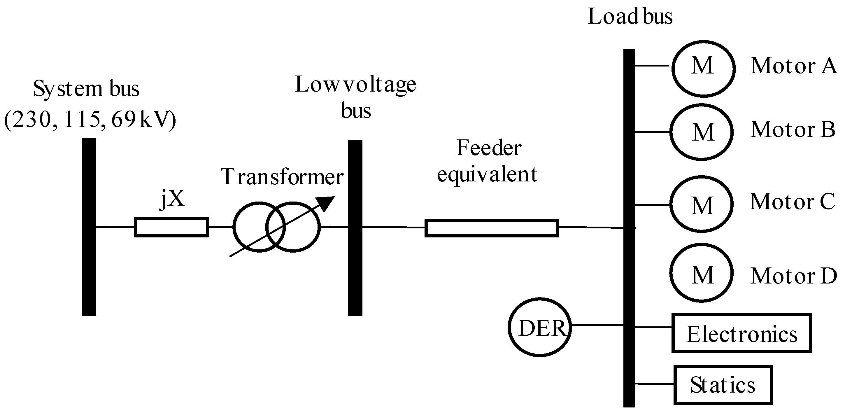
Figure 2.
Block diagram for fifth order model for indction motor
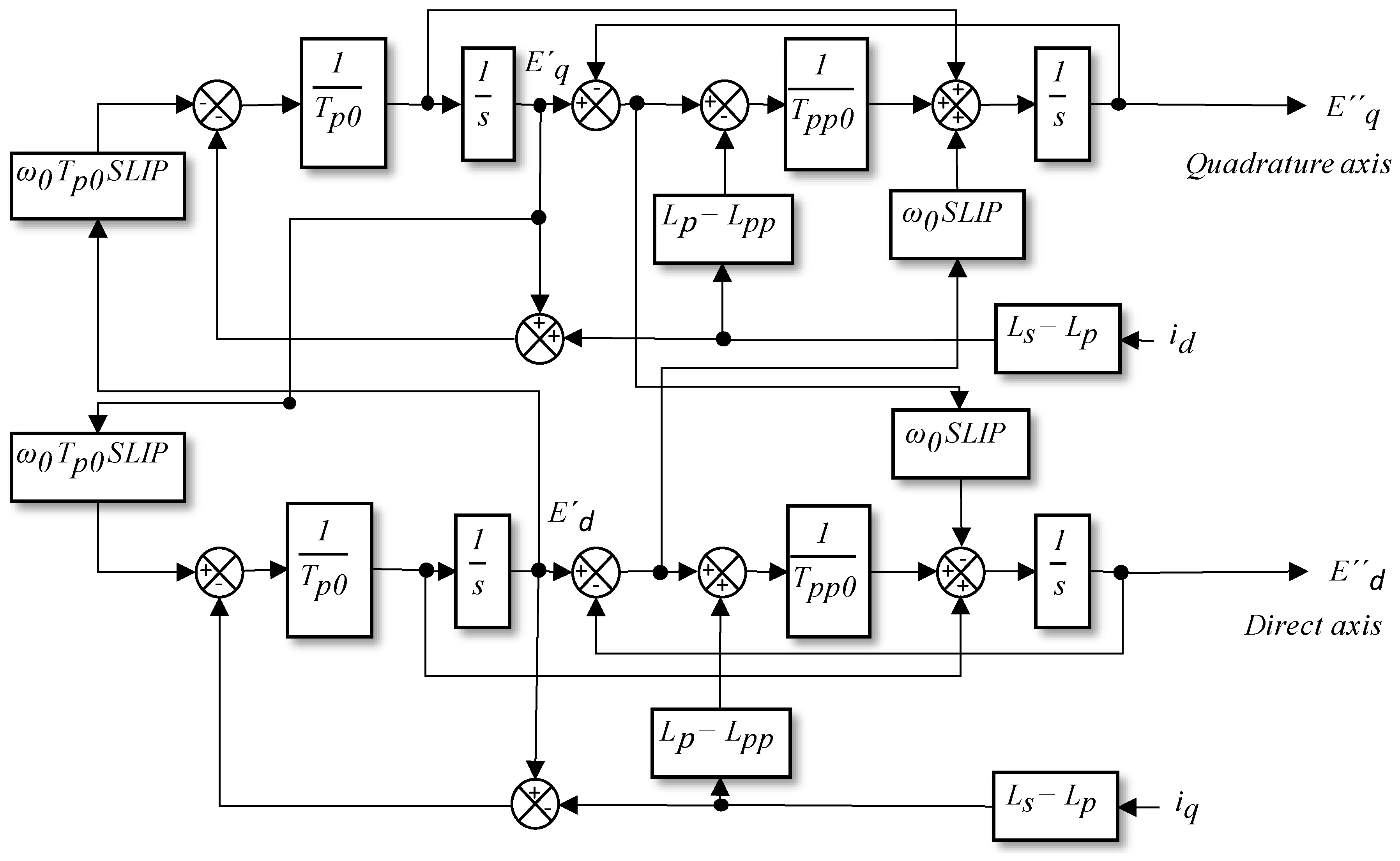
Figure 3.
Block diagram to determine Id and Iq
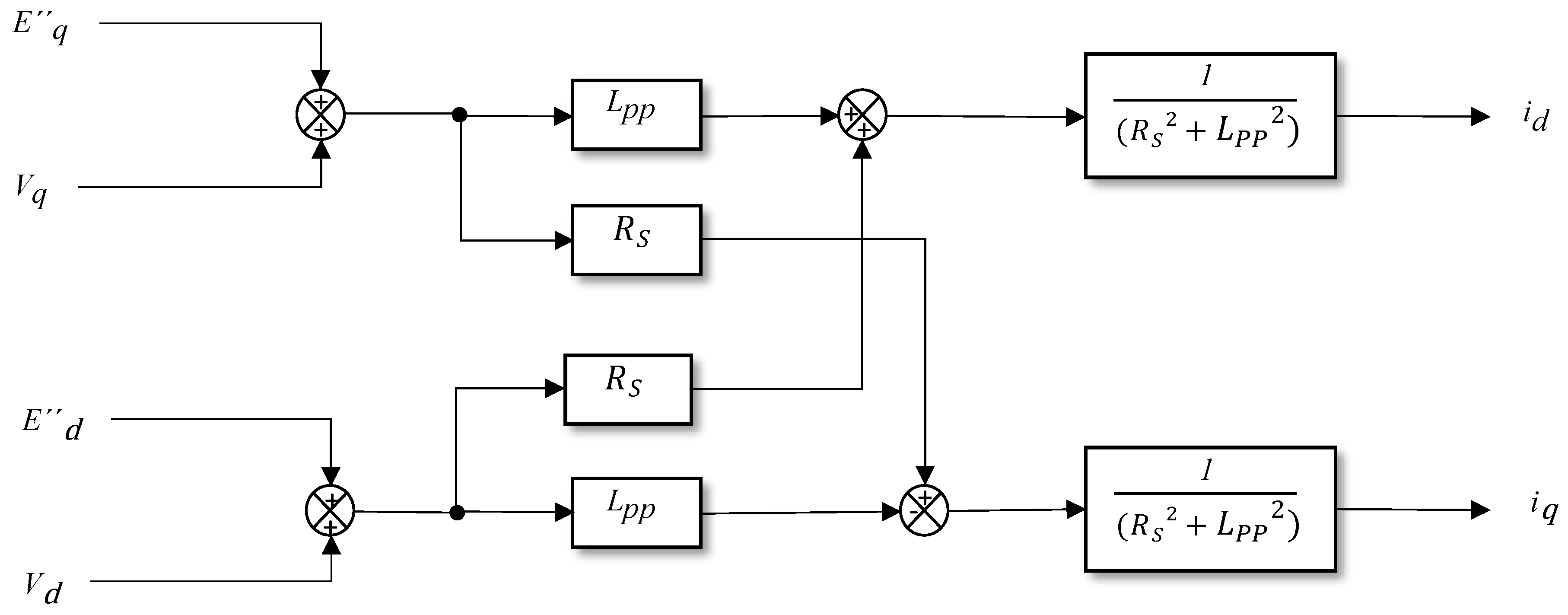
Figure 4.
Electrical torque & mechanical torque of the motor during start-up
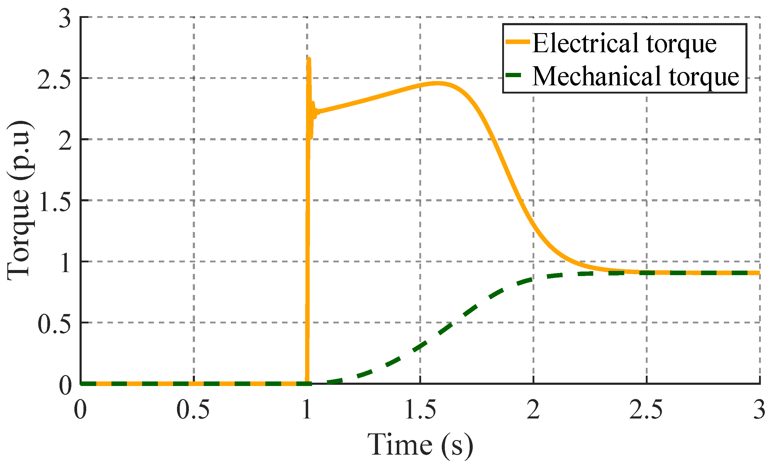
Figure 5.
Speed of the motor during start-up
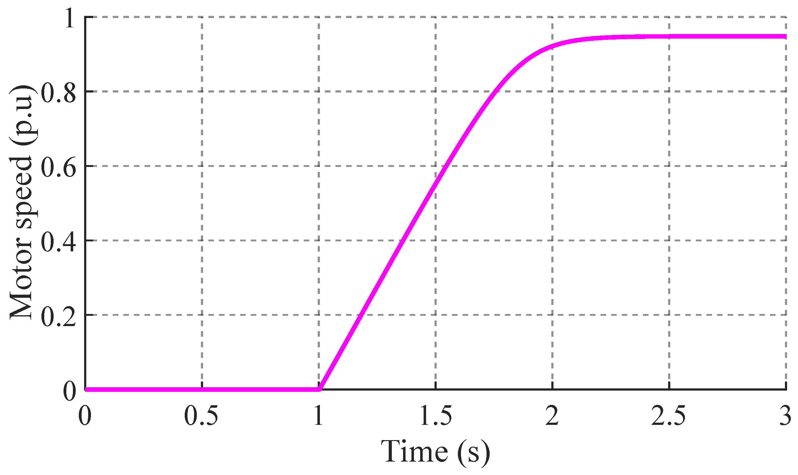
Figure 6.
Direct and quadrature axis voltage ( and )
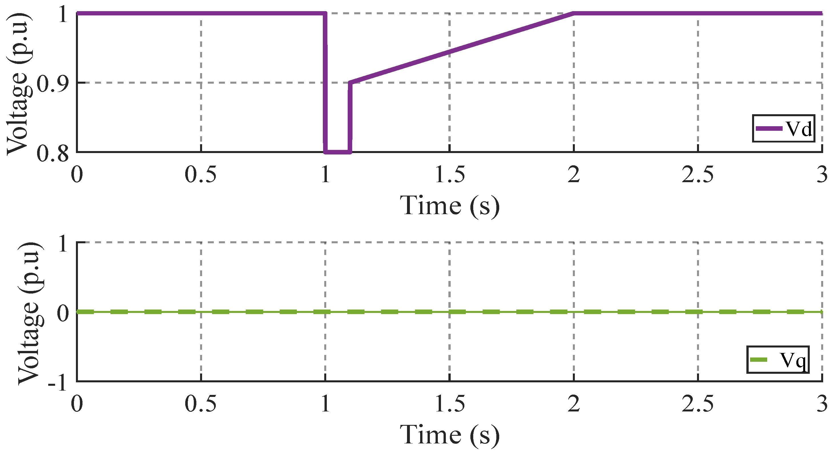
Figure 7.
Motor speed response
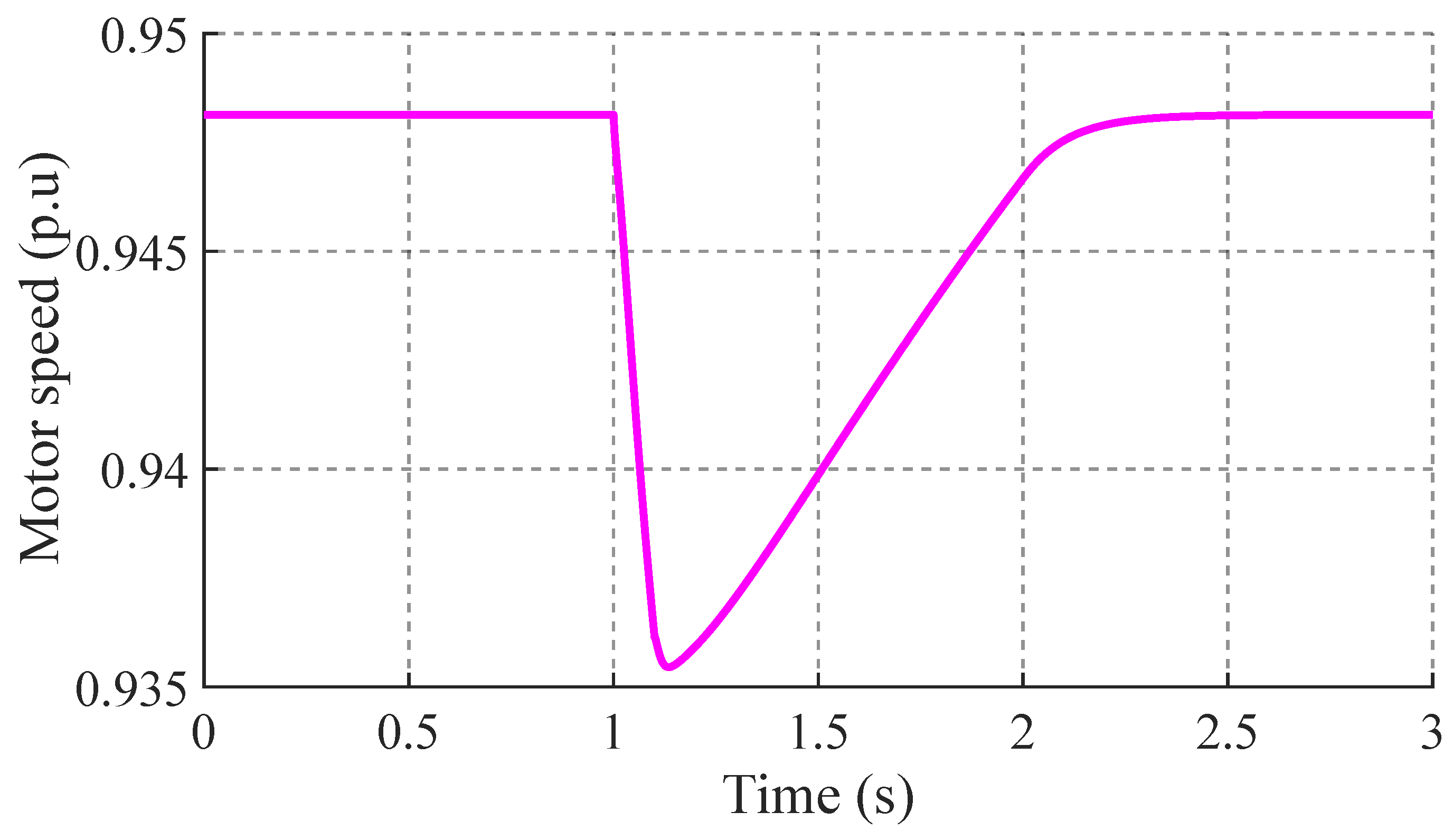
Figure 8.
Active power response
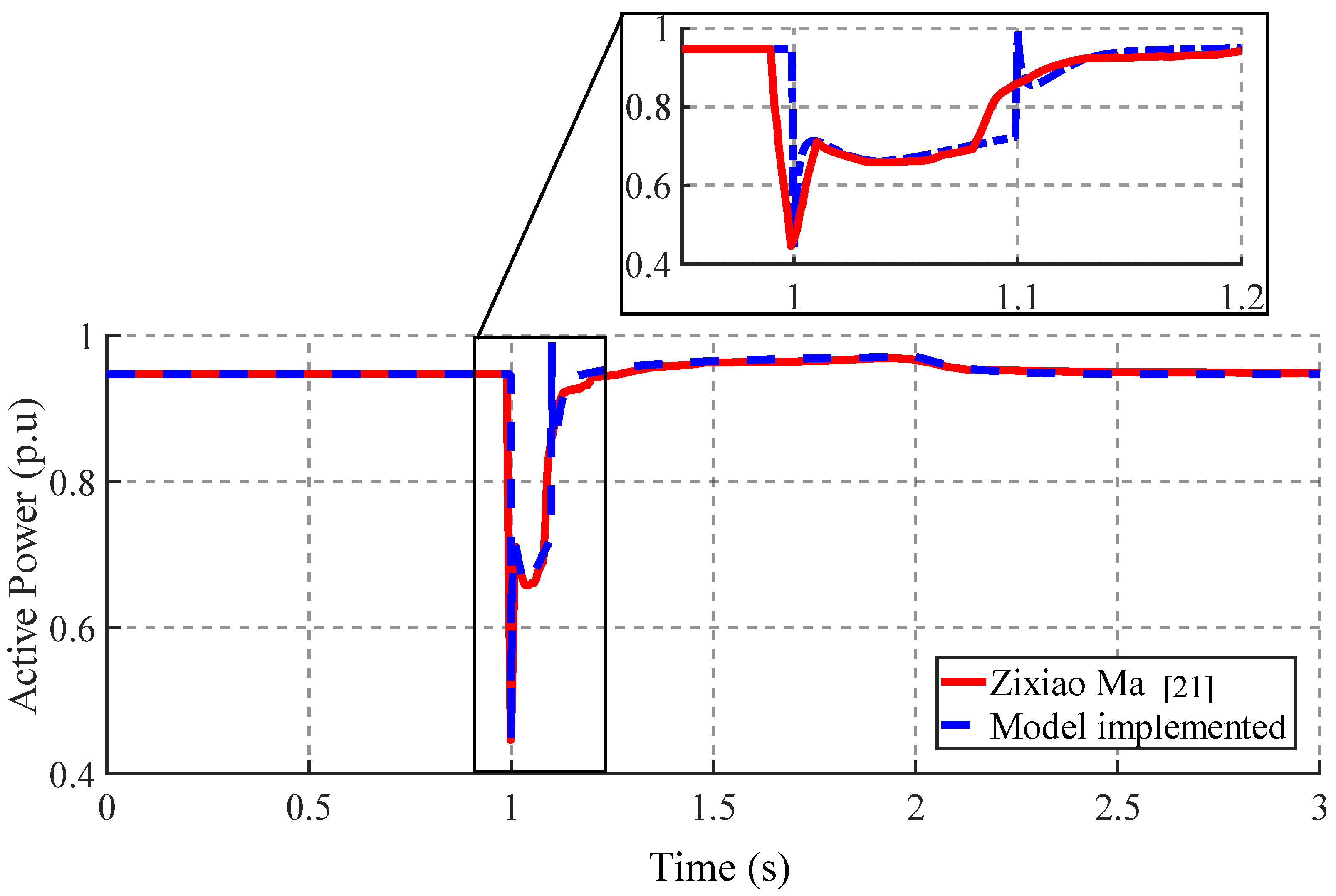
Figure 9.
Reactive power response
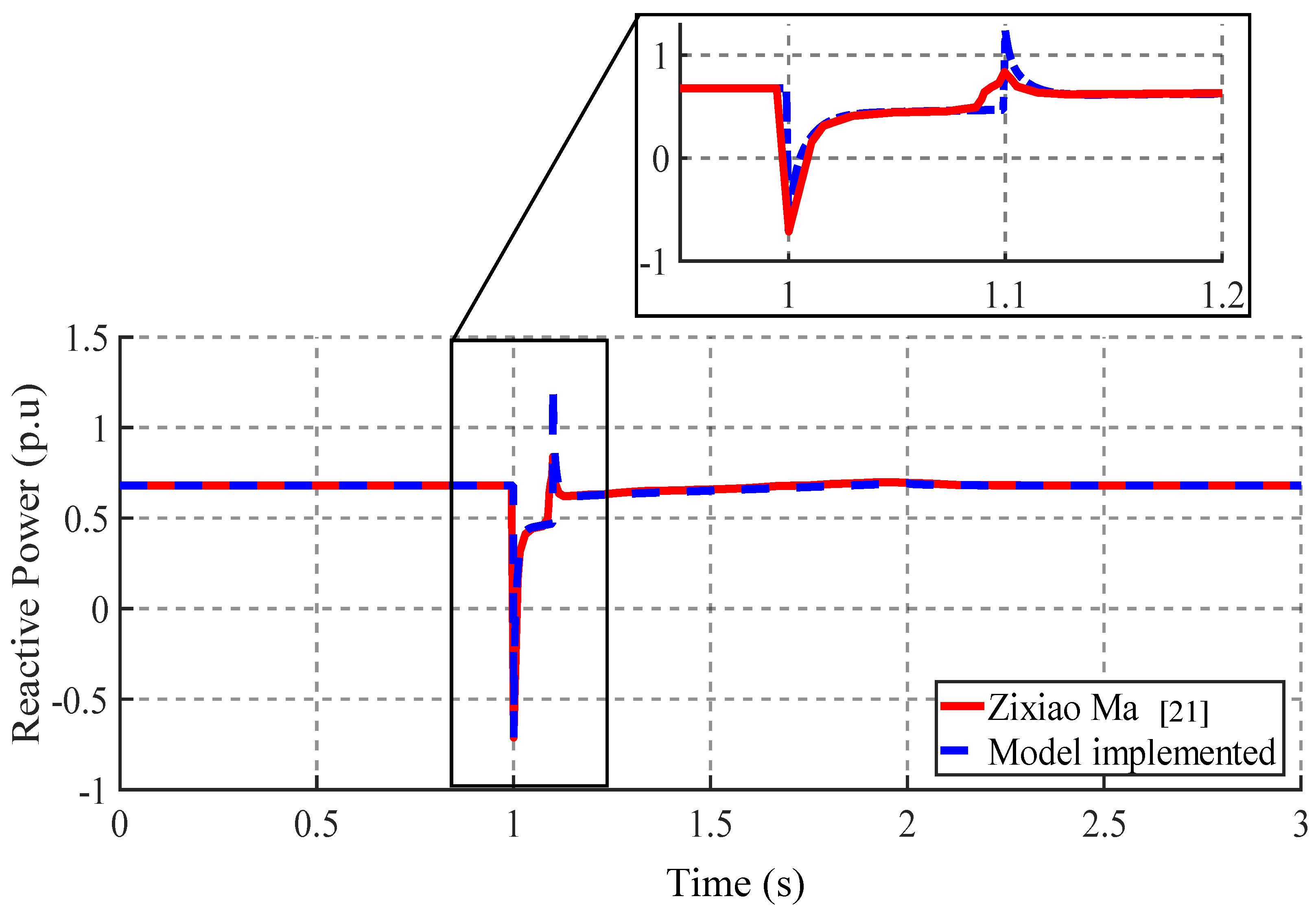

Table 1.
Parameters of motor B.
| H | Etrq | 0 | ||||||
| 0.03 p.u. | 1.8 p.u. | 0.16 p.u. | 0.12 p.u. | 0.1 s | 0.0026 s | 1 s | 2 | 120 πrad/s |
Disclaimer/Publisher’s Note: The statements, opinions and data contained in all publications are solely those of the individual author(s) and contributor(s) and not of MDPI and/or the editor(s). MDPI and/or the editor(s) disclaim responsibility for any injury to people or property resulting from any ideas, methods, instructions or products referred to in the content. |
© 2024 by the authors. Licensee MDPI, Basel, Switzerland. This article is an open access article distributed under the terms and conditions of the Creative Commons Attribution (CC BY) license (https://creativecommons.org/licenses/by/4.0/).
Copyright: This open access article is published under a Creative Commons CC BY 4.0 license, which permit the free download, distribution, and reuse, provided that the author and preprint are cited in any reuse.


