
Submitted:
19 November 2024
Posted:
20 November 2024
You are already at the latest version
Abstract
One of the most sensitive parts of a wind turbine to environmental influences are the rotating blades. Today there are many technologies available to assess its condition, but they all need to be developed to become more cost-effective and more sensitive to fault detection. The Modal Passport algorithms and methods discussed in this paper proposes the technique already used for helicopter blade condition monitoring and diagnostics. This technique requires adaptation to wind turbine blades because they have larger dimensions, material and design, and operate under other conditions. To provide this adaptation, computational and experimental data on the modal properties of the blades must be obtained. The study is planned to be performed for a scale model on stationary and rotating test rigs. The algorithms and methods of the Modal passport considered in this study stage were used to form a roadmap for developing the passport for a series of composite models of a wind turbine blade. The stages of the Modal passport development include FE modeling of the blade model and calculation of modal parameters. Estimated volume of modal tests made it possible to plan the step-by-step execution of the roadmap works for development and experimental application of the modal passport of wind turbine blade models.
Keywords:
wind turbine blade
; modal parameters
; Modal Passport
1. Introduction
Rotating blades are critical components of any machine and fiberglass rotor blades are regarded as the most vulnerable components of a large wind turbine [1]. Blade failure leads to economic losses and often to environmental damage. To ensure operational safety and to reduce potential failure costs, the non-destructive testing (NDT) methods for wind turbine blades are widely used. The authors in [2] categorize NDT methods into those that detect surface and subsurface defects. For instance, visual techniques consider inspection by workers suspended on ropes, and different optic systems may inspect blades from the ground or using drones [3]. For remote detection of corrosion of metal blades of offshore turbines, the special electrochemical sensors are considered in [4]. To detect subsurface defects, thermography, X-ray imaging, 3D laser inspection, and ultrasonic testing [5] are commonly used. Thermography is capable of detecting subsurface defects close to the surface [6]. X-ray imaging allows detecting a wide range of defects at a certain depth, but requires expensive and bulky equipment [7]. 3D Laser-Scanning Inspection is more effective for manufacturing than for operation [8]. Ultrasonic testing [9] including specialized UT techniques such as phased array UT Eddy Current Testing of Wind Turbine [10] are also effective in manufacturing but application in operation is complicated. Thus, a wide range of NDTs applied to wind turbine blades [11] allows detecting almost all types of defects, but their use in operation is limited, complicated or too expensive. Firstly, currently used techniques for blade condition monitoring is not cost-effective. The application of most NDT methods requires stopping the facility that reduces operating time. In addition, the cost of monitoring is high due to both expensive equipment and the transportation costs to the facility and back. This is especially true for offshore wind turbines. Secondly, the NDT of stationary blades has limited efficiency, since it may miss the latent defects that may be detected only during rotation under operating loads. It is also important that the time interval between NDT inspections with turbine stopping may be sufficient for some defects to develop to failure.
A blade condition monitoring method becomes cost-effective if, firstly, it can be used without stopping the wind turbine operation, and secondly, it provides predictive methods of maintenance. The diagnostics implemented by such techniques must be highly sensitive to defects at an early stage of their development. Given the “green” requirements, this also means monitoring the interaction of the blade with the environment. In some cases, the entry of a foreign object, such as a drone or a large bird, can cause damage that can subsequently lead to the destruction of the blade. In others, the rotating blade may harm the environment by getting in the way of a flock of migratory birds. The system providing diagnosing the structural integrity using vibrations measured by the sensor network allows the comprehensive solution to the problem of blade condition monitoring. Some studies were dedicated to application of the methods based on measuring the vibration response of blade when it is excited using piezo-ceramic actuator patches bonded to the blade [12]. While these methods allow a high level of localization, they require intervention in the blade design, the consequences of which may be unknown and require study. Another way is demonstrated by the in situ wireless SHM system based on an acoustic emission (AE) technique [13]. Such techniques allow localizing the acoustic sources which could emulate impact damage or audible cracks caused by different objects, such as tools, bird strikes, or strong hail. For practical application of such system, it is necessary to solve the problems of the cost of large sensors number and measurement systems, and the high probability of false alarms. Various methods of contactless monitoring of the rotating blades that do not require built-in measurement systems are proposed. For example, the authors in [14] propose to use condition assessment of full-scale blades in operation with stereo digital image correlation applying the new reference frame constructed in the center of blades rotation. Such non-contact monitoring is relatively low-cost however, it has limited resolution of the defect scale and is insensitive to real-time impacts.
For providing predictive maintenance of blades in operation authors consider the techniques of Operational Modal Analysis (OMA) as the most promising. The relation between physical properties and modal parameters (frequency, mode shape and damping) of the structure is the basis of this approach [15]. The main benefit of OMA is that modal properties of the blade can be determined using naturally excited vibrations without artificial impacts. Thus, any change of blade’s mechanical features would cause the change of modal parameters. The use of OMA allows evaluating modal properties of the blade related to its mechanical properties without stopping operation. There are many examples of using OMA to obtain the frequency and shape of vibration modes of different structures, including wind turbine blades [16,17]. A common problem in most published works is the influence of operational and ambient factors both on the mechanical properties of blade and on the modal estimates of these properties.
Wind turbine blades operate under cyclically (daily and seasonal) changing conditions, and their rotation speed fluctuates continuously. As studies of a hollow composite structure have shown, a tensile load similar to the action of centrifugal forces on a blade [18] and an ambient temperature [19] significantly influence the modal properties, even if the blade’s state does not change. This means that the modal properties of the blade operating under variable temperature and speed may vary in a range that can significantly exceed the changes caused by a defect. There are also methodological problems in OMA application caused by the influence of random nature of excitation [20]. In practical application, the limited time interval for vibration measurement plays a role. Due to non-stationary aerodynamic excitation of blade vibrations, the limited measurement time leads to an error in determining the modal parameters. Another error occurs due to the discrepancy between the characteristics of real excitation and the basic assumption of the OMA application, which considers an excitation as uniform in the frequency and time domain. The set of techniques called the Modal Passport (MP) was proposed [21] allowing to take into account an influence of operation mode (rotation speed and pitching) and atmospheric factors (temperature, wind speed, etc.) and to reduce errors of OMA estimation.
A network of sensors providing vibration measurements over the blade, similar to the peripheral nervous system, is the obligatory condition for OMA application. Such a network will allow detecting even a small local impact, for example, a collision with a bird. The sensors and their wiring unit should be integrated into the blade design, while having a minimal effect on its mechanical properties. The frequency range of the measured signals should cover a frequency range of blade’s natural modes as well as the response on a foreign object impact. The lower modes of large wind turbine blade may have frequency less than 1 Hz, while to ensure sensitivity to external impacts on the blade, the range should cover several kHz. One of the most popular sensor types is a continuous optical sensor with Fiber Bragg Grating. There are examples of such sensors application for wind turbine blades [22] and helicopter [23]. Up to moment, some features of optical sensors can limit their use for blades. Thus, the significant mass and dimensions of the measurement equipment do not yet allow the use of optics for a helicopter blade. For a large-scale wind turbine blade, the mass and dimensions are not critical, but there are issues with integrating the sensors into the blade design. The piezoelectric films could be alternative type of sensors applicable for blades due to beneficial combination of minimal mass, thickness, and negligible cost with a wide frequency range [24].
This paper is part of the study on adaptation of the MP techniques for monitoring the wind turbine blades using the piezoelectric films as vibration sensors. Section 2 discusses the program, methods, and blade model samples required for adaptation of the MP for blade models.
2. Materials and Methods
2.1. Problem Analysis
The use of MP for monitoring the blade of an operating wind turbine involves determining the modal properties of blades and taking into account the influence of operating mode and ambient conditions. The algorithms for calculating the modal parameters using measured vibrations and accounting the influence factors are the core of MP. The set of technical solutions for measuring vibrations of a rotating blade and transmitting data is the basic provision of actual MP application. Successful trials of MP application for diagnosing the helicopter blades [21] allows expecting positive results for wind turbines, provided that their specialties are taken into account. The design of wind turbine blades and their operating conditions differ significantly from helicopters. Firstly, the modal properties of helicopter and wind turbine blades differ in material, design and dimensions. Secondly, the rotation speed of a wind blade is noticeably less. Given these differences, it is necessary to adapt proven in helicopter the technical solutions and the MP algorithms to real wind turbine blades. The research works on adaptation of the MP on full-scale blades requires significant costs and a long time. They can be reduced by first carrying out the adaptation on the scaled models in laboratory conditions. Successful results of the study on models will confirm the feasibility and reduce the amount of work on adapting the MP to full-scale additions.
The objective of this study is to analyze the content and to assess the volume of experimental studies on adaptation of the MP for wind turbine blades using blade models as specimens.
2.2. Modal Passport
2.2.1. Concept
The MP concept provides an assessment of the structure's condition based on its modal parameters, taking into account the influence of the operating mode and external factors. The passport is developed for a specific blade type and takes into account the range of operating modes and external conditions.
The MP includes a typical and an individual part. The first one characterizes a virtual "typical" blade that has properties common to all blades of this type. These properties are characterized by the modal model having the parameters of typical modes, and by the influence functions of operational and ambient factors on the typical modal parameters. The typical part of MP also includes the techniques of testing, recording and processing data applicable to all blades of this type, as well as the threshold values of diagnostic parameters. All components of the typical passport are determined based on test data for blades of the chosen type. The typical MP of the blade is based on the set of blade samples used for testing. The set of typical modes is the principal part of the MP, and each of those is characterized by basic parameters: frequency, damping and shape. The individual part of the MP contains modal parameters obtained from vibration measurement data for a specific blade, using methods of recording and processing data of the typical MP. The individual part of the passport exists only for particular blade containing parameters of its modes regarded to the typical ones. Besides, the individual MP of particular blade includes information on the parameters of external and operational factors, under which vibration of the blade was measured. Ambien (atmospheric) influence is mainly characterized by temperature, while the pitch and rotation speed allow taking into account the influence of static loads on the modal properties of the operating blade. The influence functions that take these factors into account allow practical diagnosing the blade using modal parameters obtained under different operating modes and external conditions. Thus, the measured data (vibration, operating and ambient parameters) from one side, and properties and functions of typical MP are used to diagnose a particular blade.
2.2.3. Diagnostics in Modal Space
The MP allows monitoring and diagnosing in the modal diagnostic space, the coordinates in which are characterized by the values of the modal parameters. The diagnostic parameter in this space is the modal distance, which measures the difference between two modal states, for instance the actual and the reference ones. The dimension (number of axes) of the space can vary depending on the tasks being solved.
The modal distance between two points in modal space, characterizing two states of one mode, is an elementary diagnostic parameter. Coordinates of the point reflecting the shape of m-th mode in the modal space have Nm axes in accordance with the number of Degrees of Freedom (DOF) of the modal model. The modal space of three basic parameters of one mode (frequency, damping and shape) has dimension Nm+2, and the maximum possible dimension of the modal space is determined by the number M of blade modes
The elementary modal space distance (MSD) along each axis is calculated as the normalized difference between the measured and reference values. The elementary diagnostic parameters (of single mode) of frequency f, damping D, and eigenvector s of the m-th mode are calculated
To diagnose a blade, an aggregate diagnostic parameter can be calculated for each basic modal parameter, taking into account all M blade modes. The aggregate parameter is normalized to the number of modes used (M), so as not to depend on their number that may vary between similar blades
An abnormal blade condition is fixed if the MSD value exceeds the threshold value [MSD]
The modal distance in the space of three basic modal parameters is used as an integral diagnostic parameter. The scales of the frequency, shape and damping parameters differ, so the integral parameter is calculated in a harmonized modal space. Harmonization is achieved by normalizing the axis of each parameter to the upper boundary of the typical distribution area. The typical distribution areas of modal parameters (frequency [f], damping [D] and shape [s]) are determined experimentally using the test series of blades of a given type [20]. Taking into account the above, the integral diagnostic parameter is calculated
where index n reflects the number of the eigenvector element (1…N).
In the harmonized scale (normalized to the upper limit of the reference state) a value exceeding 1.0 indicates that the blade has gone beyond the normal state.
2.3. Blade Passport Preparation and Application
The MP application for blades monitoring becomes possible after the typical passport is created for the specific type of blades. The sequence of steps for MP development and its application for diagnosis and monitoring is illustrated by the diagram in Figure 1. The research and testing works are divided into 9 steps, which colors illustrate to what stage it relate. The first two steps (grey) relate to developing the typical passport for specific type of blades. Algorithms and procedures of steps 8 and 9 (green) relate to applying the individual passport for diagnosing the particular blade, and the remaining (blew) steps are used both in the stage of typical passport formation and in the use of an individual passport.
2.3.1. Blade’s Modal Model
The MP is based on the modal model of the blade, common to all samples of this type. The parameters of the model are determined by the mechanical properties of materials and design of the blade. The design specialties influence modal properties. The model of solid helicopter blade demonstrates mainly natural modes of beam kind, including bending and torsional ones. Although wind turbine blades also have an aerodynamic profile, they differ from helicopter ones, having a reinforced shell with a cylindrical root part for connection to the rotor. This specialty provides different shell modes in addition to bending ones. Initially, the modal parameters of the blade model are estimated using FE modeling methods. These modal estimates ensure the planning of the testing stage including measurement set up. The modal model is validated applying the modal testing techniques, primarily OMA. To interpret the blade vibrations measured by sensors during testing, modal analysis methods use DOFs vectors of the blade geometric model which sample is illustrated in Figure 2.
The resolution of the modal analysis depends on the DOF number of the geometric model. The more of them, the closer it may be to the modal model, and the greater the number of vibration modes the OMA can identify. The number and distribution of the vibration sensors in the natural blade, which determine the DOFs configuration, can be limited by the capabilities of the measurement system and cost considerations. Thus, having the developed modal model of a blade, it is necessary to find the optimal DOF configuration for the geometric model, taking into account both the capabilities of the measurement system and the desired resolution. The frequencies and shapes of the simulated modes allow someone to correlate the order of modes corresponding to the desired resolution with the number of necessary sensors and the required frequency range.
2.3.2. The Typical Set of Modes
The MP is able to diagnose the blade using the parameters of typical modes common to all blades of a given type. The composition of typical modes and its parameters are determined during tests of a batch of identical blades under reference conditions. As the typical only those modes are considered that are detected in the majority of tested samples of the batch. Adaptation of the MP to wind turbines is initially carried out on a batch of scaled models of such blades. The materials and design of the blade models correspond to the full-scale blades and manufactured samples are used to conduct modal tests for determining the typical modes and their parameters. The number of typical modes that can be determined based on the test results depends on the DOF number and configuration. Given the experience of using the MP for helicopter blades, it can presumably be from 10 to 30.
2.3.3. The Typical Set of Modes
When testing each blade’s model sample, the MP uses the parameters of only those modes that correspond to the typical ones. Excitation and measurement of the sample to determine the modal parameters is carried out in accordance with typical vibration testing and recording procedures. For a stationary sample, the testing procedure includes the parameters of vibration excitation, including the location, strength, direction and duration of the pulse impacts. For a rotating sample, these procedures consider the routines of signals measurement and recording over a range of rotation speed and, if necessary, with additional aerodynamic excitation. In order to ensure the calculation of parameters and identification of typical modes, the procedures of signal registration consider the frequency range of measurement, the sampling frequency and the duration of records. Depending on test conditions the registration procedure may provide for continuous registration or repeated records depending on the operational (rotation frequency) and external (atmospheric) factors. Optimization of the registration procedures decrease the error of modal parameters determination due to reducing the influence of random factors. For wind turbine blades, these factors are mainly the fluctuations of rotation speed and pitch caused by wind speed and its direction variations, as well as ambient temperature. The application of procedures is discussed in more detail in 2.5.
2.3.4. Testing and Data Recording Procedures
When testing each blade’s model sample, the MP uses the parameters of only those modes that correspond to the typical ones. Excitation and measurement of the sample to determine the modal parameters is carried out in accordance with typical vibration testing and recording procedures. For a stationary sample, the testing procedure includes the parameters of vibration excitation, including the location, strength, direction and duration of the pulse impacts. For a rotating sample, these procedures consider the routines of signals measurement and recording over a range of rotation speed and, if necessary, with additional aerodynamic excitation. In order to ensure the calculation of parameters and identification of typical modes, the procedures of signal registration consider the frequency range of measurement, the sampling frequency and the duration of records. Depending on test conditions the registration procedure may provide for continuous registration or repeated records depending on the operational (rotation frequency) and external (atmospheric) factors. Optimization of the registration procedures decrease the error of modal parameters determination due to reducing the influence of random factors. For wind turbine blades, these factors are mainly the fluctuations of rotation speed and pitch caused by wind speed and its direction variations, as well as ambient temperature. The application of procedures is discussed in more detail in 2.5.
2.3.5. Estimation of Modal Parameters
For the initial assessment of modal parameters, OMA methods use vibration signals measured during tests and transformed into digital form. For modal estimation the commercially available software (SW) packages are applied. This SW relates recorded data to DOFs of the geometric model and realizes the most usable OMA techniques. Each such technique (estimator) identifies natural modes of the tested blade and provides primary estimates of those modes parameters (frequency, damping and shape). Such estimates are not applicable for health monitoring due to uncertainty caused by random component of structural vibrations and measurement errors. The latter becomes evident when different OMA estimators identify blade’s modes differently developing the same test data. The influence of random vibration component on the uncertainty is expressed in the modal estimates variation of the same estimator when processing repeated tests of the same blade.
2.3.6. Modal Enhancement
The modal enhancement allows reducing the uncertainty of primary estimated modal parameters. There are two stages of primary estimates developing: the preparation and the averaging.
Preparation stage considers the sequence of eigenvector transformations, including modal shape normalizing, modes grouping and modal phase matching. Different estimators of commercial SW provide different scales of eigenvectors describing the modal shape. Normalizing the modal shape to a common (-1.0... 1.0) range allows compatibility of eigenvectors provided by different estimators. Each n-th element of the eigenvector of the m-th mode computed by the modal estimator is normalized
The modal grouping procedure includes identifying the similar modes from the set of primary estimates with normalized shapes. The Modal Assurance Criterion (MAC) [25] allows identifying the similar modes comparing the pair of its eigenvectors. If MAC tends to 1.0 the pair of mode shapes is almost identical. As a criterion for similarity the minimum acceptable MAC that depends on blade specifics is fixed. For instance, for the similar modes detection from estimates of experimental data of helicopter blades the lower MAC limit at 0,98 was applied successfully. The similar modes with MAC exceeding the lower limit are clustered in the similar modal groups. By results of modal grouping the K unique groups of modes are selected, and each group includes the similar sustainable modes. The preparation stage is completing with phase matching within each group of modal estimates. The matching is required as OMA estimators may reflect an eigenvector of the same mode in opposite phases. The matching involves the check of phase compatibility between modes in the group and inversion of the eigenvectors with opposite phases.
The modal enhancement reduces uncertainty of computed modal parameters and increases accuracy of diagnostics using these parameters. The enhancement procedures differ for eigenvalues (frequency and damping) and for eigenvectors describing the modal shapes. For m-th mode the enhanced mean of frequency and damping are calculated as the arithmetic mean of the estimates of the k-th group
The enhancement procedure for modal shape considers averaging each of N elements of prepared eigenvectors for each k-th group
Uncertainty of the enhanced modal parameters is estimated using assumption for Gaussian distribution of primary modal estimates. Such assumption was proven by distribution of modal OMA estimates experimentally obtained for helicopter blades that turned out to be close to normal [20]. Distribution area of enhanced modal parameters with 99,7% probability with Gaussian distribution is characterized by triple standard deviation of its estimates
The uncertainty of the enhanced eigenvector is estimated for each n-th element of enhanced eigenvector by triple standard deviation in the group of modes and is presented as a vector
As global parameter of uncertainty of m-th mode the scalar value may be used
The enhanced modal parameters computed from the test data using Eq. (11) and Eq. (12) reflect mathematical expectation of the modal properties of the tested blade. The values calculated using Eq. (13), (14) and (15) characterize the uncertainty level, with which these parameters are calculated.
2.3.7. Modal Parameters of Typical Modes
The MP diagnoses the particular blade comparing the modal parameters calculated using measured vibration with the reference state parameters. The set of modes identified as a result of the test of the particular sample only partially coincides with the typical modes. Therefore, from the modes computed from measured vibrations, only those that are similar to typical ones are selected for diagnostics. The selection of modes is performed using MAC, which compares the enhanced eigenvectors with typical ones [25]. A MAC value close to 1.0 indicates the similarity of the compared modes. For example, a MAC of at least 0.98 was used as the threshold for selecting modes of hollow composite structures [18]. The parameters of the selected modes characterize the current state of the blade and are used for subsequent MP procedures.
2.3.8. Influence Functions
Blade health monitoring should be provided in different conditions, depending on wind speed, and at different temperatures. As shown in modal studies of composite structures [19], atmospheric temperature, affecting the mechanical properties of the material, can significantly change the modal parameters. The rotating blade is a subject of centrifugal and bending/torsional aerodynamic loads, the static component of which also affects the modal properties of the composite structure [18]. Since the threshold values of the diagnostic parameters are set for reference conditions, it is necessary to consider the influence of the above factors on the measured modal parameters. In MP, the influence of external factors is taken into account by influence functions that in laboratory conditions (for scaled models) are determined experimentally. The test procedure and the equipment used are discussed in more detail in Section 2.5.
Influence functions express the deviation of the modal parameter from the reference value in response to changes in the influencing factor. Modal passport considers the modal parameter as function of difference between actual and reference value of operating factor. The dependences for modal parameters on temperature are shown in Eq.16
For instance, frequency on temperature influence function indicates gradient of m-th mode frequency for 10C temperature change. The frequency influence functions are common for all samples (blade models) in determined range . Though modal frequencies at reference state may slightly vary between samples, MP considers they have the same frequency increment for the same temperature change. Influence functions are determined experimentally by testing the batch of samples in operating range of an influencing factor. On top of temperature the static loads are the influencing factors also. An operating blade is subject of two static loads: the tensile load caused by centrifugal forces and depending on rotation speed, and bending/twisting forces depending also on a blade pitch. Thus, for rotating blade (and its scaled model) the influence functions of static loads and temperature to be defined for all modal parameters in operating range.
2.3.9. Reduced and Normalized Modal Parameters
Commonly, modal parameters of the vibrating blade are evaluated under arbitrary conditions, for instance characterized by load L and temperature T. If they differ from reference values, for which the thresholds are defined, the computed modal parameters should be recalculated to reference conditions () using influence functions. For instance, considering linear superposition of two or more impact factors the recalculation of the modal frequency for m-th mode is derived from Eq.16
By the same way the parameters of damping and eigenvector could be recalculated
After reduction to reference conditions the blade modal parameters could be normalized to reference values in a similar way to Eq.2-4.
2.3.10. Blade Diagnosis
Modal parameters reduced to reference conditions and normalized are used to calculate diagnostic parameters in accordance with equations 2-7 and 9. In dependence on the number of modal components used in the state space the diagnostic parameters are divided into three levels: integral (for a whole blade or sample), aggregate (one kind of parameters), and elementary. Some samples of the blade diagnosis applying different kinds of modal parameters are considered below.
The blade condition assessment begins with the use of the integral parameter (Eq.9), which considers all the modal parameters identified during testing. Since the parameter is calculated on a normalized scale, the integral blade condition can be assessed without taking into account its history, i.e. based on the data of a single test. From the definition of the integral parameter, it follows that if its value is less than 1.0, the blade condition remains in a reference state.
Exceeding the specified limit indicates an abnormal condition, which reason can be determined considering the relationship of the aggregate parameters of frequency, damping and shape (Eq.5-7). For example, sun radiation "aging” the composite material of the entire blade may lead to a uniform decrease in the stiffness over the blade. With a stiffness loss, the global parameters of blade’s modes (frequency and damping) change more, while the normalized mode shapes may change less. A similar effect can be exerted by moisture absorption, which increases the mass of the material of most of the blade that leads to a change in its modal properties. Another type of damage, such as loosening of the blade fastening, would change dominantly the parameters of the low-frequency modes, and the higher an order the effect less. If the shape aggregate parameters play a dominant role in the anomaly, then the latent defect may be identified, and the damage can be localized. For localization the elementary diagnostic parameters are used (Eq.2-4). These parameters characterize the change in individual modes, and those of them would respond, for which the damage location is near the highest stress zones.
The modal passport allows not only monitoring of a particular blade, but also diagnostics of blades based on the data of single test or measurement. In this case, the parameters of a virtual "typical" blade are used for comparison, but not the parameters of reference state of this blade. Such diagnostics can be used to reject blades with hidden defects for which there are no data from previous tests.
2.4. Testing Models of Blades
For experimental studies required to adapt the MP algorithms and procedures to wind turbine blades the scaled blade models are manufactured. The materials (fiberglass plastic) similar to typical blades and the hollow design with reinforcement elements are used for these models manufacturing. The number of samples is determined based on the research objectives and the test program. The main objective is to develop a typical MP of the samples (blade models), and the parameters of this MP will be the more accurate, the greater the number of samples tested. In addition, the samples might be used to study the seeded fault influence on modal parameters. In practice, time and cost factors limit the number of samples, so it is determined taking into account the minimum number that ensures the solution of the test problems. A typical wind turbine rotor has 3 blades, so the test setup for blade models testing (described in Section 2.5) is also designed for a rotor with 3 blades. Taking into account the possible replacement of the blade set, a minimum number of 6 identical models was determined. The batch of 6 samples was accepted as the minimum sufficient in order to develop the typical MP of the samples. Technical requirements for blade models and the testing equipment required are given in Table 1.
Sizes of the projected thermal chamber and the rotor test bench limit the maximum length (2 m) of the blade model. The mass and size of the measurement unit, which has to be placed on the rotating hub of the bench, limits the channel number (24). As simultaneously signals of maximum 24 sensors can be measured, the sensors number of the sample was also limited to 24. The temperature range for model testing (-15…+45) was reduced compared to the operating conditions of full-scale blades, since the testing task is limited by the development of the MP adaptation technique. The upper limit of the rotation speed range (900 rpm) is selected taking into account the criteria of similarity to the peripheral speeds at the ends of full-scale blades. The model design with integrated sensors is illustrated in Figure 3.
In this study, piezoelectric films are used as sensors, allowing to measure dynamic stresses of the surface layer of vibrating blade model. Location of the sensors on the inner surface of samples was chosen similar to that planned for the full-scale wind turbine blades. This solution allows preventing the impact of precipitation, dust and other environmental factors on the sensor network. The location of the sensors, taking into account its limited number, will be determined based on the results of the FE modeling in accordance with the considerations of paragraph 2.3.1. The wiring system is common to all sensors and ends with the connector for the cable connecting the blade to the measurement unit on the rotor hub. The root part of the model is reinforced to provide cantilever fastening and to transmit dynamic and static loads in different test modes.
2.5. Testing and Measurement Systems
The special test equipment and the measurement system are prepared for testing the models. The test equipment provides several functions. Firstly, it simulates external effects to which a wind turbine blade is exposed in natural conditions. Secondly, it provides dynamic excitation of non-rotating blade model in accordance with the OMA requirements. Thirdly, it provides measurement and recording of signals of the vibrating blade as well as parameters of external factors (temperature, rotation speed and pitch). In dependence on the test mode the parameters of dynamic excitation of the sample are chosen to provide a typical set of modes. The measurement system allows recording vibration of the blade model during testing, as well as the parameters of external effects, including temperature and rotation speed. Two benches, the thermal chamber and the rotating bench, will be used together and separately to conduct tests related to the formation of a modal passport.
2.5.1. Rotating Test Rig
The bench for testing blade models in rotation is used to study modal properties under the action of centrifugal and bending loads. To solve this problem, Data Acquisition Unit (DAU) measures the vibration signals of the blade model rotating with the rotor at a given rotation speed. The projected bench layout is shown in Figure 4.
The horizontal plane of rotation was chosen to simplify the design and reduce the bench sizes. The blade model is mounted to the rotor hub through the ring mount on the root part. The design of the hub and the model’s root allows installing all three samples with the same pitch, which may be regulated in a given range. The model’s pitch can be additionally adjusted within limited range for aerodynamic balancing of the rotor. The DC electric drive of the bench provides the rotor with blades rotation speed in the range from 0 to 900 rpm, the upper limit of which corresponds to the peripheral speed of the blade tip of about 0.8 M. The rotating part of the measurement system, installed on the hub, measures and converts the signals from the blade sensors, and transmits them online for registration to the computer of the fixed part of the system. Here, the files are generated using the data obtained during the tests, for which the estimates of modal parameters (p. 2.3.4) and their modal enhancement (p. 2.3.5) are calculated.
By conducting a series of model tests at several rotation speeds, it is possible to determine the dependence of each modal parameter of this model on the rotation speed in a given range. By repeating the tests for each of three rotor blade models, it will be possible to determine the general dependence of the modal parameters on the rotation speed for these models type. As the part of the MP of the blade models, influence functions ensure the reduction of the modal parameters obtained at an arbitrary rotation speed to the reference rotation speed. The design of the bench also allows researching the dependence of the modal parameters on the pitch.
2.5.2. Thermal Testing Chamber
The thermal chamber rig provides modal tests of the blade model installed on a rotating bench as the part of the rotor. By such a way the boundary conditions correspond to the rotating blade although without centrifugal force. The testing set up using the thermal chamber is shown in Figure 5. To excite vibrations of non-rotating blade model, the automatic pulse actuator acts on sample’s root being inside the thermal chamber that provides given temperature. The impact force and duration of the excitation are regulated to achieve vibrations of the sample in a given frequency range, sufficient to determine the parameters of typical modes. The pause between impacts is determined as the time duration sufficient for measuring the model's response to impacts. The thermal chamber design provides for input of the cables for actuator control and the model's sensor network.
The testing and registration procedures for a statically fixed blade may take a significant amount of time, during which the temperature must remain constant. The thermal control system maintains a stable temperature at a given level in automatic mode. Automatic vibration excitation and thermal control systems ensure repeatability of test conditions for a series of models. The tests in a thermal chamber provide a consistent solution to two problems. First, tests are carried out at a reference temperature. Based on the results of these tests, using the modal estimation (p. 2.3.4) and modal enhancement (p. 2.3.5) procedures, a typical set of modes and their parameters are determined. Modal tests to determine the parameters of a typical MP are carried out on all 6 samples of the blade models. Second, the temperature influence functions on the modal parameters of models are determined in the temperature range from minus 150C to plus 450C. The influence functions will be determined for three blade models that are part of the rotor. The result of the blade models testing in a thermal chamber will be the typical set of modal parameters at the reference condition and the typical influence functions of modal parameters, including frequency, shape and damping.
2.6. Measurement System
Measurement system, as it is shown in Figure 4, comprises rotating and stationary part.
Rotating part is placed on the rotor and includes:
- 20 piezoelectric sensors, embedded into blade model;
- rotation speed sensor;
- two 12-channel Data Acquisition Units (DAU) connected via a switch and powered by batteries;
- Wi-Fi transmitter, connected to DAU;
- cables from the sensors connecting to DAU.
Stationary part, remote from rotating test bench to a safe distance, includes Wi-Fi receiver, connected to computer, and computer with installed software, providing measurement system control, data registration and monitoring.
The measurement system provides synchronous measurement of 24 inputs with a sampling rate of 8192 Hz and a bit rate of 24 bits. Data from the DAU are transmitted to a remote computer at 300 MB/sec.
3. Results
Adaptation of the MP for the blade model requires a significant amount of experimental research. To estimate the upcoming works the number of tests and analyzed modes must be taken into account. For roughly estimating the modal properties (modes number and frequency range) the FE model was used (Figure 6).
For considered study stage the frequency range was limited to 400 Hz. Modal frequencies of first 16 calculated modes in this range are presented in Table 2.
Aiming for optimization of the sensor network for manufactures samples the shapes of calculated modes were identified. The indices of the identified modes are given in the 3rd row of the table. The letter index designates the type of oscillation mode (F - flapping, R - rotation, T -torsional, S - shell), and the number in front means the order of these mode kind. For modes that have both beam and shell features, both indexes are indicated. Figure 7 illustrates examples of a typical beam mode using the 4th flapping - 4F in Figure 7a and shell 2TS in Figure 7b. Table 2 shows that up to 200 Hz the modes have beam kind, while at higher frequencies some shell modes appear. The reason is that cylindrical (hollow) composite samples having relatively thin walls combine the properties of a beam and a shell.
The sensor network configuration should be sensitive to various potential defects that can differently affect beam (like loss of material rigidity) and shell (like local skin surface defects) modes. Considering above, an arrangement of sensors in a chain along the sample provides mainly identifying the beam-type modes, while sensors located along the chord allow also identifying local shell modes. Thus, to identify two half-waves along the chord, observed in the 2TS shape (Figure 7b), at least 4 sensors are required in this direction. Considering the limited number of sensors in the planned tests, the configuration 4x6 was selected, where 4 sensors in each of 6 sections are distributed along the blade. Such a configuration will allow identifying both shell modes with 1-2 half-waves, and beam modes up to 5 inclusive. Taking into account the order of potentially detectable modes corresponding to indices 5F and 2TS, the upper limit of the frequency range of the modal parameters study is estimated about 400 Hz. According to the simulation results, 15 modes fall into this range. Taking into account the approximation of the calculation results, as well as a possible influence of test conditions on the mode frequencies, the upper limit is up to 600 Hz.
Experience in experimental studies of the modal properties of composite samples [20] showed that the number of modes identified using the test results can be two or more times greater than their calculated number. Thus, the number of natural modes identified by the OMA methods for each model test is preliminarily estimated up to 30.
Preliminary assessment of the frequency range of modal studies, the number and order of modes allowed to preliminarily estimate the main parameters of the MP model, as well as to estimate the score of the laboratory research program. Table 3 indicates the scope of basic stages of the research study, including number of the tests and evaluation blade modal properties.
At the first stage, the data recording procedures are optimized that ensure reliable identifying of modal parameters of the blade models. These procedures will be experimentally checked for the lower and upper boundaries of the modal test range. Within the framework of this stage, the optimal parameters of testing procedures are determined, which ensure reliable identification of sustainable modes common to all samples. For stationary model tests (n=0), these are the parameters of pulse excitation, duration of vibration signal recording, and number of repeated tests. For the rotation test mode, the procedures also provide for the necessity and type of additional aerodynamic impacts on the rotating blade required to ensure sufficient excitation. To optimize the data recording procedures, it is planned to use at least two models, conducting 5 tests for each. The tests are carried out at the reference conditions (preliminary +150C; n=0) and boundary operation modes. For modal estimation the commercial SW Artemis will be applied that uses 5 principal estimators to assess each data set. The result of processing the data from each test is expected up to 30 modal data sets, each of which includes parameters of frequency, damping and shape. Up to 6000 modal data sets are planned to be acquired and processed in the first stage that will allow developing the testing data recording procedures. These procedures will be common for all samples, and will be used both at the stage of MP development and its experimental application for each of blade models.
Applying the typical procedures developed, the next stage will involve modal tests of all (6) samples in order to determine the typical set of modes and the distribution area of their modal parameters. Based on the testing experience of helicopter blade models [21], the program considers three tests for each sample. Using the data of an expected 2700 modal data sets, the parameters of typical modes for all samples will be determined. The actual spread of modal parameters will be estimated based on the difference between modal parameters of the typical set and of particular samples.
The largest volume of tests is intended to determine the temperature influence functions. Three blade models, assembled with a rotor and installed on the test bench, participate in the test series. At each temperature specified in the Table 3, three tests of each sample will be carried out. The set of modal parameters identified using the test data will provide three sets of dependencies of modal parameters on temperature for each sample. Averaged dependencies provides the set of influence functions that are common for all samples. Supposedly, 15750 modal data sets will be used to determine the temperature influence functions of the blade models.
To determine the influence functions of rotation speed on modal parameters, it is planned to obtain and process about 9000 modal data sets. The tests will be carried out in 4 operation modes (rotation speed), covering a range of frequencies, the relative width of which exceeds the range of rotation frequencies of a full-scale wind generator in operating modes.
Thus, the preliminary estimate of the data that will be required to form the MP of the wind turbine blade model may exceed 33,000 modal data sets.
4. Discussion
The algorithms and methods of the Modal passport considered in this study stage were used to form a roadmap for developing the passport for a series of composite models of a wind turbine blade. The stages of the Modal passport development include FE modeling of the blade model and calculation of modal parameters, and the consequence of modal testing stages aiming for:
- validation of the modeled parameters using scaled manufactured blade models;
- development of typical testing and data recording procedures;
- determination of the typical set of sustainable modes using the modal enhancement technique;
- determination of influence functions using experimental setups;
- normalization of diagnostic parameters for blade models state diagnostics using thresholds of diagnostic parameters.
5. Conclusions and Future Works
The example of sensor network optimization for the blade model is presented, including consideration of integrated network of piezoelectric film sensors. The pre-designed testing facilities and measurement set-up will provide testing the samples of blade models. The data obtained using FE simulation allowed estimating the score of experimental studies for the development of the modal passport of wind turbine blade models. Estimated volume of modal tests made it possible to plan the step-by-step execution of the roadmap works for development and experimental application of the modal passport of wind turbine blade models.
In accordance with the blade model and technical requirements presented in the article, the models of wind turbine blades will be manufactured. The models will be tested using test setups, which was presented in Section 2.5. Based on the test results, the MP of the wind turbine blade model will be formed.
In the next research stage, the experience of determining a typical set of modal parameters and typical influence functions of models will be used for real wind turbine blades. Dependences on the rotation frequency and temperature will be determined using a database of vibration measurements and operating parameters of full-scale wind turbines. Such data, accumulated with seasonal variance, will allow, using the experience of laboratory tests, to determine a typical set of modal parameters for the reference state of a specific type of full-scale blades. The same data will be used to determine the dependences of each modal parameter on the rotation frequency, temperature and pitch. Such dependences will ensure the determination of influence functions and the use of MP for monitoring and diagnostics of full-scale blades.
Author Contributions
Conceptualization, A.M.; methodology, A.M. and P.D.; software, P.D.; validation, A.M.., P.D and A.S.; formal analysis, A.M.; writing—original draft preparation, data curation; writing—review and editing, P.D.; visualization, P.D. and A.S.; project administration, A.M.; funding acquisition, A.M.. All authors have read and agreed to the published version of the manuscript.
Funding
Please add: This research was funded by CENTRAL FINANCE AND CONTRACTING AGENCY REPUBLIC OF LATVIA, project number 1.2.1.2.i.2124ACFLA_003 ”Enhancing the efficiency of green energy objects through prospective vibration diagnostic techniques“.
Data Availability Statement
Data is unavailable due to privacy.
Acknowledgments
The administrative and technical support of this research is supported was provided by Center of Competence in Energy and Transport (SIA “ETKC”).
Conflicts of Interest
The authors declare no conflicts of interest.
References
- Drewry, M.; Georgiou, G. A review of NDT techniques for wind turbines. Insight 2007, 49, 137–141. [Google Scholar] [CrossRef]
- Dimitrova, M.; Aminzadeh, A.; Meiabadi, M.S.; Sattarpanah Karganroudi, S.; Taheri, H.; Ibrahim, H. A Survey on Non-Destructive Smart Inspection of Wind Turbine Blades Based on Industry 4.0 Strategy. Applied Mechanics 2022, 3, 1299–1327. [Google Scholar] [CrossRef]
- Shihavuddin, A.S.; Chen, X.; Fedorov, V.; Christensen, A.N.; Brogaard Riis, N.A.; Branner, K.; Bjorholm Dahl, A.; Reinhold Paulsen, R. Wind turbine surface damage detection by deep learning aided drone inspection analysis. Energies 2019, 12, 676. [Google Scholar] [CrossRef]
- Ahuir-Torres, J.I.; Bausch, N.; Farrar, A.; Webb, S.; Simandjuntak, S.; Nash, A.; Thomas, B.; Muna, J.; Jonsson, C.; Mathew, D. Benchmarking parameters for remote electrochemical corrosion detection and monitoring of offshore wind turbine structures. Wind. Energy 2019, 22, 857–876. [Google Scholar] [CrossRef]
- LeBlanc, B.; Niezrecki, C.; Avitabile, P.; Chen, J.; Sherwood, J. Damage detection and full surface characterization of a wind turbine blade using three-dimensional digital image correlation. Struct. Health Monit. 2013, 12, 430–439. [Google Scholar] [CrossRef]
- Karganroudi; Sattarpanah, S.; Aminzadeh, A.; Ibrahim, H.; Rahmatabadi, D.; Francois, V.; Cuillière, J.-C. A Novel Automated Approach for Geometric Reconstruction and Flexible Remanufacturing of Spur Gears Using Point Cloud Mapping Analysis. Comp. -Aided Des. Appl. 2023, 20, 92–108. [Google Scholar]
- Liu, Y.; Hajj, M.; Bao, Y. Review of robot-based damage assessment for offshore wind turbines. Renew. Sustain. Energy Rev. 2022, 158, 112187. [Google Scholar] [CrossRef]
- Marks, R.; Gillam, C.; Clarke, A.; Armstrong, J.; Pullin, R. Damage detection in a composite wind turbine blade using 3D scanning laser vibrometry. Proc. Inst. Mech. Eng. Part C J. Mech. Eng. Sci. 2017, 231, 3024–3041. [Google Scholar] [CrossRef]
- Márquez, F.P.G.; Chacón, A.M.P. A review of non-destructive testing on wind turbines blades. Renew. Energy 2020, 161, 998–1010. [Google Scholar] [CrossRef]
- Available online: https://www.zetec.com/blog/wind-turbine-nondestructive-testing-what-you-need-to-know/ (accessed on 26 September 2024).
- Márquez, F.P.G.; Chacón, A.M.P. ; A review of non-destructive testing on wind turbines blades. Renewable Energy 2020, 161, 998–1010. [Google Scholar] [CrossRef]
- Ghoshal, A.; Sundaresan, M.J.; Schulz, M.J.; Pai, P.F. Structural health monitoring techniques for wind turbine blades. Journal of Wind Engineering and Industrial Aerodynamics 2000, 85, 309–324. [Google Scholar] [CrossRef]
- Bouzid, O.; Cumanan, K.; Moore, D. Structural Health Monitoring of Wind Turbine Blades: Acoustic Source Localization Using Wireless Sensor Networks. Journal of Sensors 2015. [Google Scholar] [CrossRef]
- Feng, W.; Yang, D.; Du, W.; Li, Q. In Situ Structural Health Monitoring of Full-Scale Wind Turbine Blades in Operation Based on Stereo Digital Image Correlation. Sustainability 2023, 15, 13783. [Google Scholar] [CrossRef]
- Maia, N.M.M.; Montalvão e Silva, J.M. Theoretical and Experimental Modal Analysis; Research Studies Press: Baldock, 1997. [Google Scholar]
- Kim, H.C.; Kim, M.H.; Choe, D.E. Structural health monitoring of towers and blades for floating offshore wind turbines using operational modal analysis and modal properties with numerical-sensor signals. Ocean Engineering 2019, 188, 106226. [Google Scholar] [CrossRef]
- Tcherniak, D.; Larsen, G. Application of OMA to an operating wind turbine: Now including vibration data from the blades. 5th International Operational Modal Analysis Conference, 2013. IOMAC 2013.
- Mironov, A.; Kovalovs, A.; Chate, A.; Safonovs, A. Static Loads Influence on Modal Properties of the Composite Cylindrical Shells with Integrated Sensor Network. Sensors 2023, 23, 3327. [Google Scholar] [CrossRef] [PubMed]
- Mironov, A.; Chate, A.; Safonovs, A.; Kuzmickis, V.; Doronkin, P. SHM System Prototype for Serial Structures Operating Under Different Conditions. EVACES 2023. Lecture Notes in Civil Engineering, vol 433. [CrossRef]
- Mironov, A.; Safonovs, A.; Mironovs, D.; Doronkin, P.; Kuzmickis, V. Health Monitoring of Serial Structures Applying Piezoelectric Film Sensors and Modal Passport. Sensors 2023, 23, 1114. [Google Scholar] [CrossRef] [PubMed]
- Mironov, A.; Doronkin, P. The Demonstrator of Structural Health Monitoring System of Helicopter Composite Blades. Procedia Structural Integrity 2022, 37, 241–249. [Google Scholar] [CrossRef]
- Arsenault, T. J.; Achuthan, A.; Marzocca, P.; Grappasonni, C.; Coppotelli, G. Development of a FBG based distributed strain sensor system for wind turbine structural health monitoring. Smart Materials and Structures 2013, 22, 075027. [Google Scholar] [CrossRef]
- Weber, S.; Kissinger, T.; Chehura, E.; Staines, S.; Barrington, J.; Mullaney, K.; Zanotti, F.L.; Petrunin, I.; James, S.; Lone, M.; Tatam, R. Application of fibre optic sensing systems to measure rotor blade structural dynamics. Mechanical Systems and Signal Processing. 2021, 158, 107758. [Google Scholar] [CrossRef]
- Mironov, A.; Doronkin, P. Piezoelectric Films Application аor Vibration Diagnostics. In Reliability and Statistics in Transportation and Communication. RelStat 2022; Kabashkin, I., Yatskiv, I., Prentkovskis, O., Eds.; Lecture Notes in Networks and Systems; Springer: Cham, 2022; vol 640. [Google Scholar] [CrossRef]
- Allemang, R. The Modal Assurance Criterion (MAC): Twenty Years of Use and Abuse. Sound and Vibration 2003, 37. [Google Scholar]
Figure 1.
The step sequence of MP creation and application.
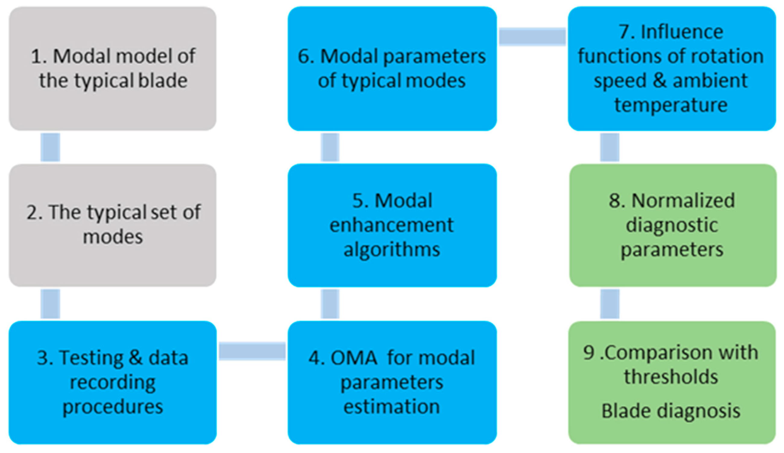
Figure 2.
The step sequence of MP creation and application.
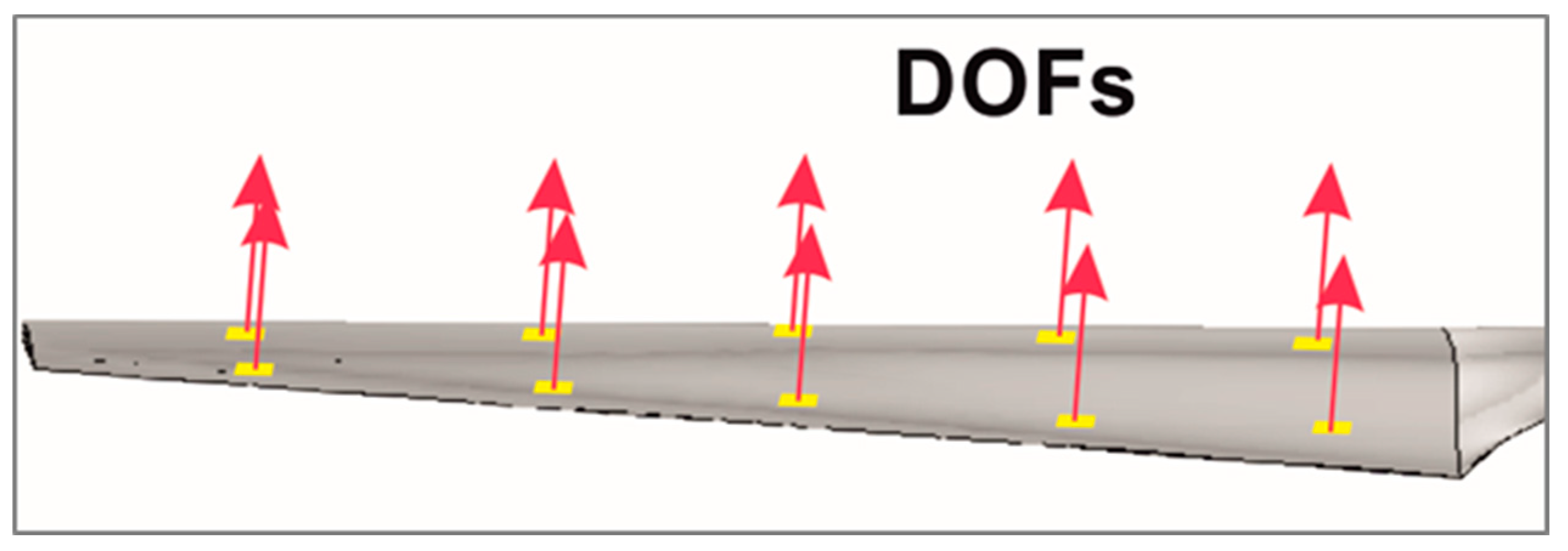
Figure 3.
General view of the blade model (a), and sensors on its inner surface (b).

Figure 4.
Rotating test bench set-up.
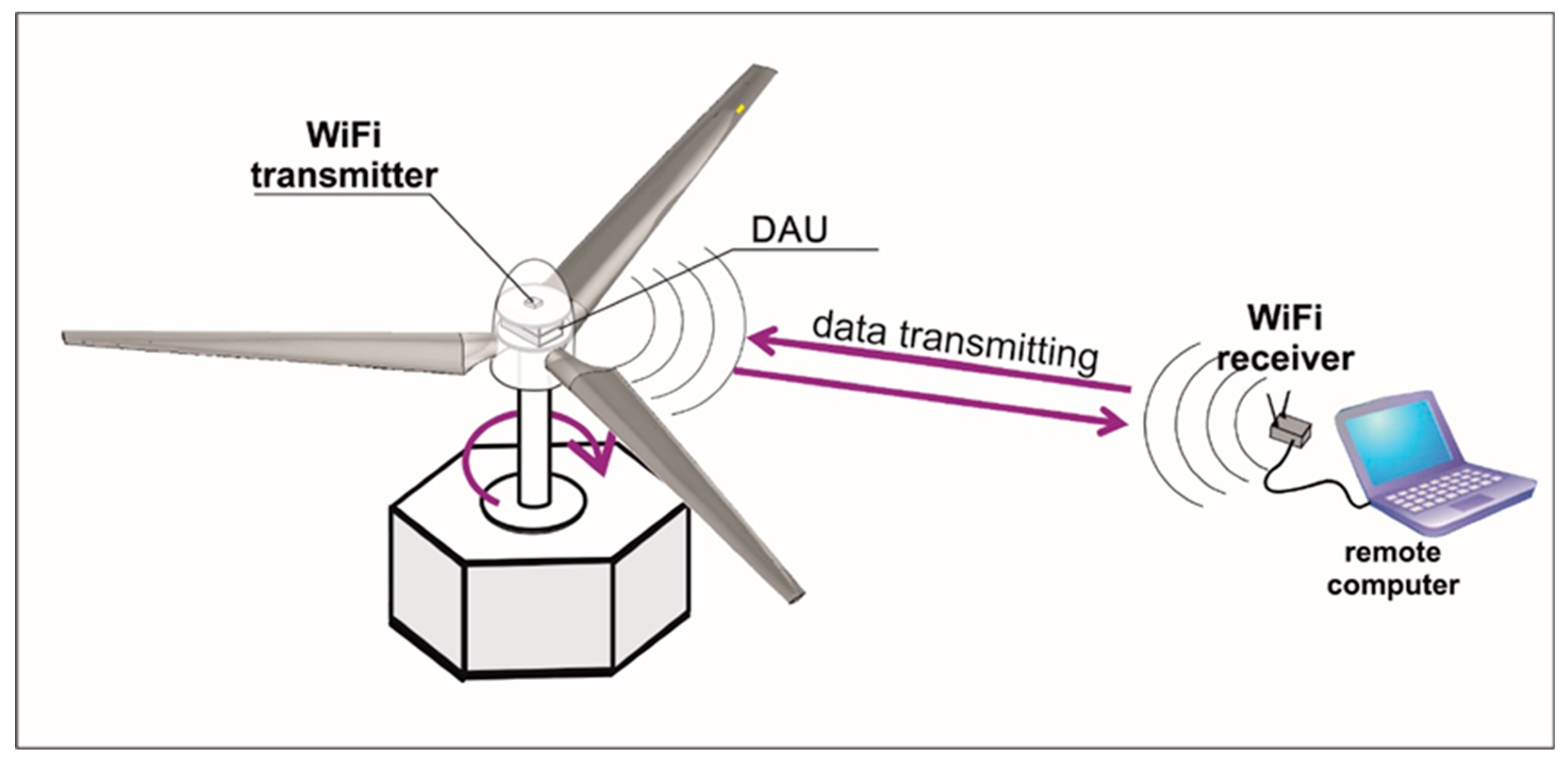
Figure 5.
Test set-up with thermal chamber covering the blade model with dynamic excitation.
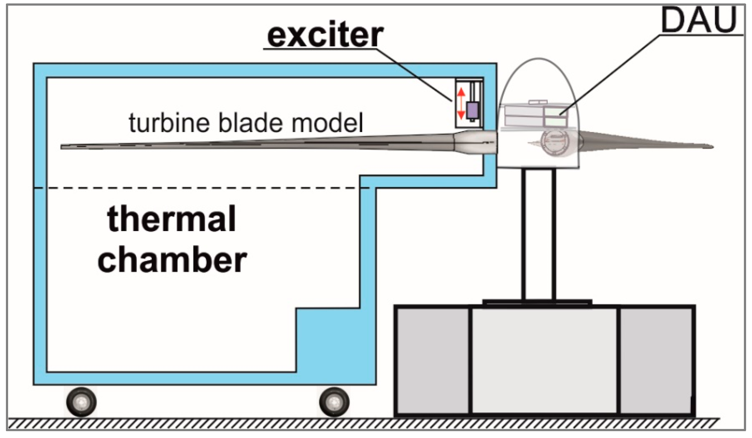
Figure 6.
Finite element model of scaled turbine blade.
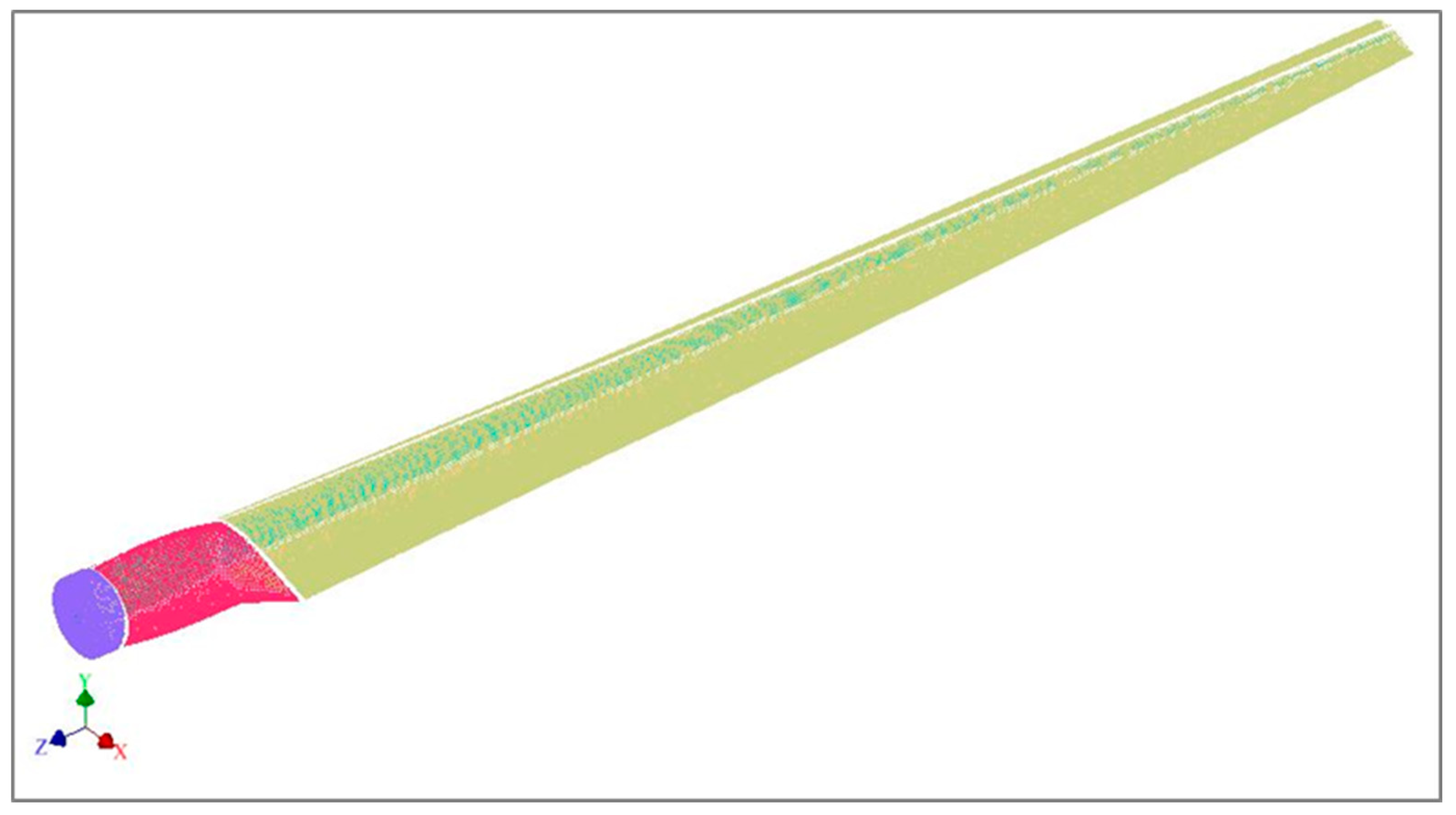
Figure 7.
Finite element model of scaled turbine blade.
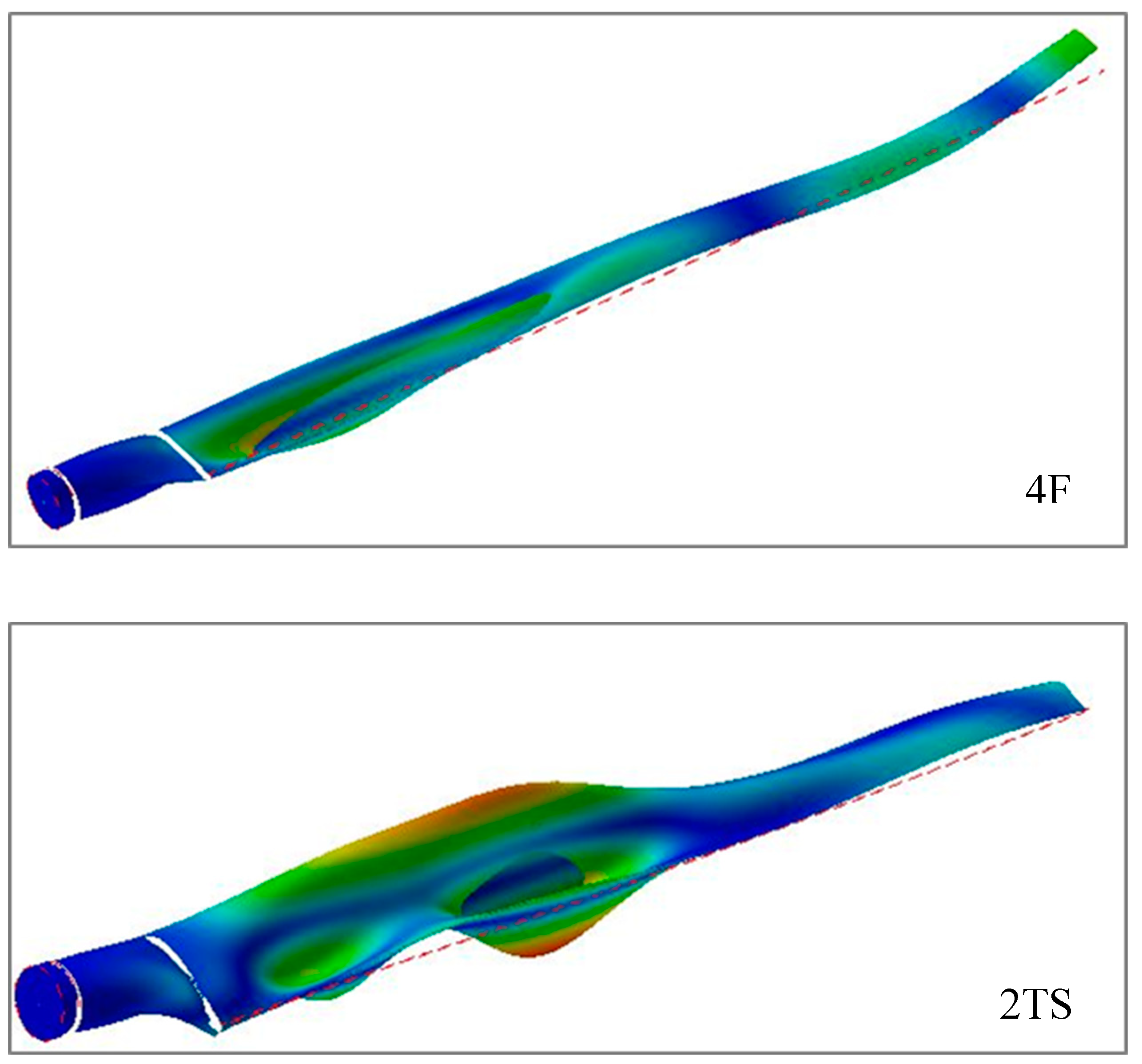

Table 1.
Technical requirements to blade models.
| No | Position | Technical solution |
|---|---|---|
| 1 | Specimen quantity, pcs, min | 6 |
| 2 | Model length, mm | 2000 |
| 3 | Sensors | |
| type | piezoelectric film PVDF | |
| size, mm | 16x73 | |
| quantity | 24 | |
| wiring | varnished copper wire | |
| placing | interior surface of the hollow model | |
| protection | sensors & wires protected by voile/ epoxide resin | |
| type | piezoelectric film PVDF | |
| 4 | Testing operation range | |
| temperature, oC rotation frequency, rpm |
-15…+45 0…900 |
Table 2.
Frequency and shape of identified modes.
| Mode | 1 | 2 | 3 | 4 | 5 | 6 | 7 | 8 | 9 | 10 | 11 | 12 | 13 | 14 | 15 | 16 |
|---|---|---|---|---|---|---|---|---|---|---|---|---|---|---|---|---|
| Freq., Hz | 21 | 38 | 70 | 147 | 171 | 204 | 211 | 257 | 259 | 291 | 303 | 339 | 352 | 358 | 380 | 404 |
| Mode index | 1F | 1R | 2F | 3F | 2R | 4F | 1S | 5F | 2S | 3RS | 6F | 7F | 8F | 2TS | 3S | 9F |
Table 3.
Expected volume of research (tests and evaluation of modal properties) of blade models.
| No | Test series |
Conditions | Quantity | Modal data sets | ||
|---|---|---|---|---|---|---|
| models | tests | estimates | ||||
| 1 | Testing & data recording procedures development total |
-150С; n=0 +150С; n=0 +450С; n=0 +150С; n=900rpm |
2 2 2 2 |
10 10 10 10 40 |
50 50 50 50 200 |
1500 1500 1500 1500 6000 |
| 2 | Typical modal parameters | +150С; n=0 | 6 | 18 | 90 | 2700 |
| 3 | Temperature influence functions total |
-150С; n=0 -50С; n=0 +50С; n=0 +150С; n=0 +250С; n=0 +350С; n=0 +450С; n=0 |
3 3 3 3 3 3 3 |
15 15 15 15 15 15 15 105 |
75 75 75 75 75 75 75 525 |
2250 2250 2250 2250 2250 2250 2250 15750 |
| 4 | Rotation frequency influence functions total |
+150С; n=600rpm +150С; n=700rpm +150С; n=800rpm +150С; n=900rpm |
3 3 3 3 |
15 15 15 15 60 |
75 75 75 75 300 |
2250 2250 2250 2250 9000 |
Disclaimer/Publisher’s Note: The statements, opinions and data contained in all publications are solely those of the individual author(s) and contributor(s) and not of MDPI and/or the editor(s). MDPI and/or the editor(s) disclaim responsibility for any injury to people or property resulting from any ideas, methods, instructions or products referred to in the content. |
© 2024 by the authors. Licensee MDPI, Basel, Switzerland. This article is an open access article distributed under the terms and conditions of the Creative Commons Attribution (CC BY) license (http://creativecommons.org/licenses/by/4.0/).
Copyright: This open access article is published under a Creative Commons CC BY 4.0 license, which permit the free download, distribution, and reuse, provided that the author and preprint are cited in any reuse.


