Submitted:
19 November 2024
Posted:
19 November 2024
You are already at the latest version
Abstract
We present a novel high-resolution complex field extraction technique utilizing the U-Net-based architecture to effectively overcome the inherent resolution limitations of polarization camera with micro-polarized array. Our method extracts high-resolution complex field information, achieving a resolution comparable to that of the original polarization camera. Enabling the parallel phase-shifting digital holography technique, we extracted high-resolution complex field information from four high-resolution phase-shifted interference patterns predicted by our network directly at the hologram plane. Being independent of numerical propagation in dataset acquisition, our network reconstructs objects at various depths without DC and conjugate noise. By training the network with real-valued interference patterns and using only a single pair of low- and high-resolution input and ground truth interference patterns, we simplify computational complexity and improve efficiency. Our simulations demonstrate the network's robustness to variations in random phase distributions and transverse shifts in the input patterns. Validation results show that images have been successfully reconstructed with improved quality and enhanced spatial resolution.
Keywords:
deep learning
; complex field extraction
; Polarized image sensor
; phase-shifting holography
; image super-resolution
1. Introduction
Digital holography (DH) allows for capturing and reconstructing three-dimensional (3D) information from real-world objects using digital sensors and numerical processing methods [1,2,3,4,5,6]. It differs from conventional holography, which captures the interference pattern on film; DH uses electronic sensors like charged-couple devices (CCD) or complementary metal-oxide semiconductors (CMOS) to record these patterns. It offers much flexibility as the holograms, when captured, can be subjected to numerical processing to remove unwanted noise and artifacts. DH is utilized in fields where high-accuracy 3D imaging is needed, including biomedical imaging and optical metrology [1,2,3]. Recently, DH has become more adaptive and intelligent by integrating artificial intelligence (AI) & machine learning, predicting complex fields and reconstructing high-quality holographic images [4,5,6].
Enhancing the resolution of holographic images in in-line digital holography (DH) is crucial in many applications as it allows for amplitude and phase imaging. The core issues that make it hard to get high-quality images are the zero-order and twin images. The phase-shifting digital holography (PSDH) technique is an effective method of improving image quality or removing noise. This method involves capturing multiple hologram images with different phase shifts to reconstruct the complex amplitude of the light field. Studies have shown that PSDH, which combines phase-shifting technology with digital holography, effectively eliminates the interference of zero-order and conjugate images [7,8,9]. Traditional phase-shifting methods utilize mechanical movements of mirrors and components or electro-optic modulators with piezoelectric transducers to introduce phase shifts [10,11,12]. They are prone to motion artefacts and misalignment errors between exposures. Researchers have developed parallel phase-shifting digital holography (PPSDH) algorithms to overcome these challenges. They used an array device that shifts optical paths with a pixelated pattern or a micro-polarizer array with different polarization directions to capture multiple holograms with varying phase shifts in one shot [13,14,15]. However, implementing this approach necessitates the design and fabrication of a complex phase mask, precise alignment of the mask within the optical system, and correction of any optical aberrations or diffraction effects introduced during the reconstruction process, which would require interdisciplinary expertise.
Researchers used a polarization-sensitive CCD sensor to overcome these problems with PPSDH because it simplifies the optical system and enhances performance [16,17,18,19,20,21,22,23]. The polarization CCD eliminates the need to design and fabricate complex phase masks and their precise alignment. These sensors comprise four subpixels, each capturing different phase shifts, enabling the simultaneous acquisition of phase-shifted holograms in a single exposure without introducing additional optical aberrations or diffraction effects. This results in a more stable and efficient setup, improving image quality and making it particularly suitable for dynamic imaging applications where speed and accuracy are essential. Polarization sensitivity enables the detection of the polarization state of light, which provides crucial insights into the material properties and structural details of the observed objects [21,22,23]. However, this configuration affects the acquired hologram's effective spatial resolution or image size. Since four subpixels represent the information at a single spatial location, the effective resolution is reduced compared to the total number of pixels on the sensor. Specifically, the spatial resolution is approximately one-fourth of the sensor's total pixel count.
To address the inherent low-resolution problem in hologram acquisition from the polarized-based image sensor, researchers have employed several hologram demosaicing techniques [24,25] to improve the resolution of the reconstructed hologram. Two primary techniques are used: the super-pixel method (SPM) and the hologram interpolation method (HIM). The SPM groups four neighbouring pixels—each corresponding to one of the four-phase shifts—into a single "unit cell," effectively ignoring the blank pixels in the sparse sub-phase-shift holograms [26,27]; this method is easy to implement but reduces both the maximum lateral spatial resolution and the image resolution of the reconstructed image to half of what is achieved in temporal PSDH in both horizontal and vertical directions. In contrast, the HIM fills in the blank pixels using values from adjacent pixels; although it is more complex than the SPM, it avoids losing image resolution. A simulation is conducted comparing the root-mean-square error of reconstructed images using HIM with bilinear, bicubic, and B-spline interpolation methods [25]. To address the limitations of both approaches, researchers have proposed hybrid and advanced techniques: By exploiting sensor-shifting or object-shifting strategies to capture multiple frames with sub-pixel displacements, algorithms can combine the four phase-shifted images to reconstruct a higher-resolution image beyond the sensor’s size.
In contrast, deep learning techniques have emerged as powerful tools for addressing inverse problems in holographic image super-resolution. By training convolutional neural networks (CNNs) on datasets comprising low-resolution (LR) and high-resolution (HR) holographic images, these networks learn mappings between them. This data-driven approach enhances the resolution and quality of holographic imaging while reducing reliance on complex physical setups [4,5,6]. In digital holographic microscopy (DHM), CNNs have been utilized to surpass the diffraction limit, thereby enhancing the spatial resolution of images beyond traditional optical constraints [28,30]. Additionally, generative adversarial networks (GANs) have been employed to improve the quality of holographic reconstruction. By learning the distribution of high-quality holographic images, GANs can generate super-resolved images from LR holograms, leading to significant improvements in both spatial resolution and image quality [31]. Moreover, deep learning models have been developed to retrieve phase information from intensity-only measurements. These models enhance holographic reconstruction by improving both phase and amplitude information, which extends the depth of field and further refines image resolution. Overall, the application of deep learning in holography represents a significant advancement, offering improved image quality and resolution without the need for more complex or expensive optical systems. These approaches leverage the power of neural networks to address limitations in traditional holographic techniques, making high-quality holographic imaging more accessible and efficient.
In this work, we present a deep-learning-based complex field extraction technique with a resolution equivalent to the total pixel count in the polarized-based CCD sensor. We utilized a U-Net-based architecture [32] to reconstruct HR images in the object plane by extracting complex field information at the hologram plane. Extracting the complex field at the hologram plane offers significant advantages. Since the complex field in this plane closely resembles the interference pattern recorded there, it allows for higher-quality extraction compared to extracting the complex field directly in the object plane. This improved extraction quality relies on four predicted HR phase-shifted interference patterns obtained from the network. Once the complex field is extracted at the hologram plane, it can be numerically propagated to any desired distance to reconstruct the object without the presence of DC and conjugate terms. A key benefit of our proposed method is that preparing the network's training dataset does not require numerical propagation. This means the trained network is independent of specific numerical propagation algorithms, providing greater flexibility. After extraction, any numerical propagation algorithm can be employed to reconstruct the object at different depths. In contrast, previous approaches that extract the object's complex field directly at the object plane require the training dataset to be prepared after numerically propagating the optically obtained complex field to the object plane. This process makes the trained network dependent on a specific numerical propagation algorithm, limiting its generalizability. By training the network with real-valued interference patterns, our method enhances holographic imaging, simplifies computational complexity, and avoids the challenges associated with processing complex-valued amplitude and phase information. Notably, the model is trained using only a single pair of LR and HR interference patterns for all examples in the dataset. Once trained, the model can use the LR counterparts as input to predict all four HR phase-shifted interference patterns. Overall, our approach not only improves the quality of complex field extraction but also offers greater flexibility and efficiency in holographic image reconstruction, making it a promising solution for HR holographic imaging applications.
Validation demonstrates the successful reconstruction of higher-quality images at specific depths using the extracted complex field information derived from the predicted four HR interference patterns
2. Methods
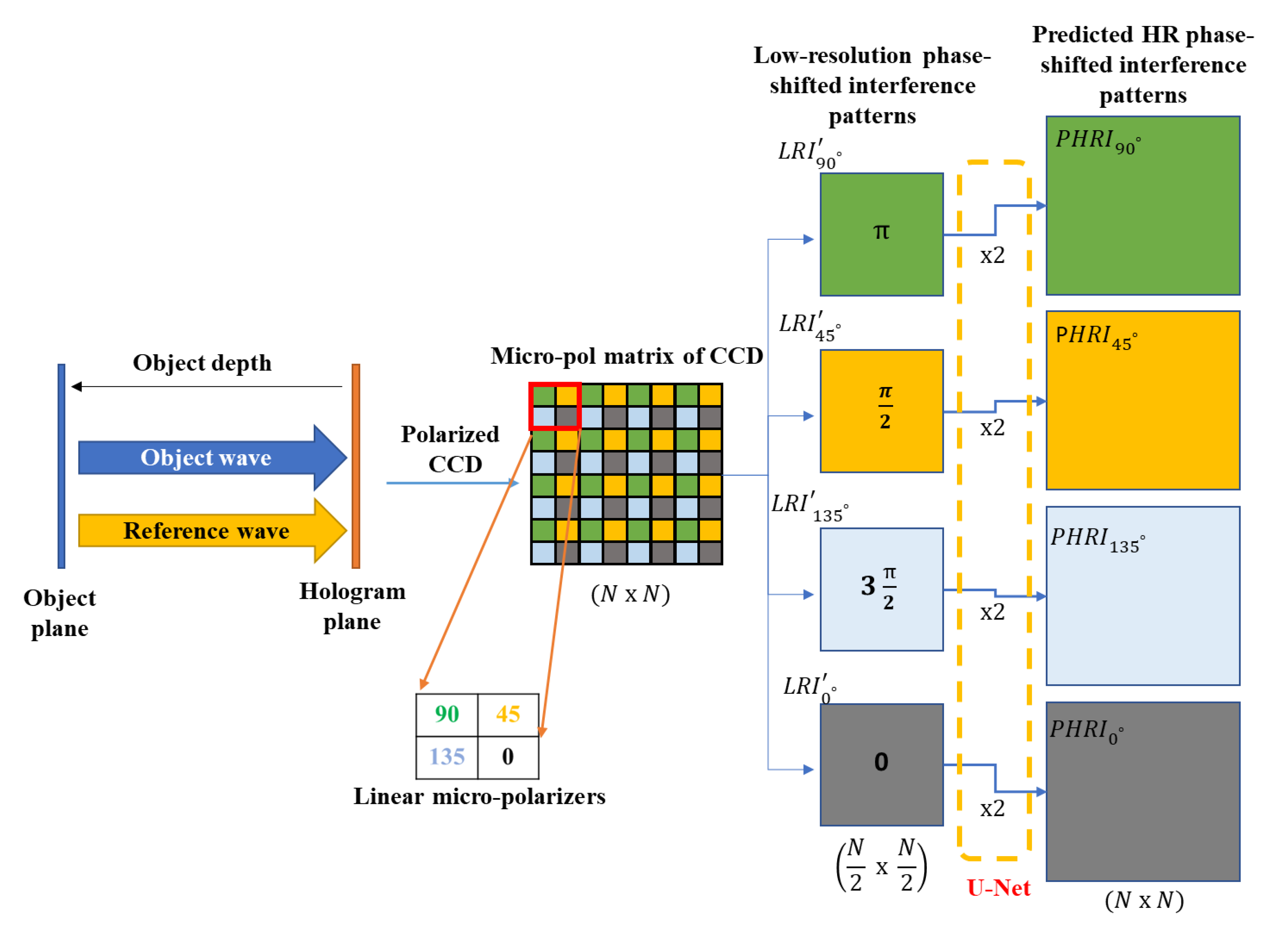
Our proposed method utilizes a U-Net-based architecture that considers the subpixel structure of a micro-polarized CCD sensor to extract HR complex field information at the hologram (sensor) plane from predicted HR interference patterns, as illustrated in Figure 1.
The camera is equipped with linear micro-polarizers oriented at angles of 0°, 45°, 90°, and 135°, each aligned with a corresponding CCD pixel. This one-to-one correspondence ensures the camera's full resolution is effectively utilized, capturing detailed phase information across the sensor. When object and reference waves with opposite circular polarization directions interfere, the phase shifts recorded by the polarized CCD are 0, π/2, π, and 3π/2 radians, corresponding to micro-polarizer orientations of 0°, 45°, 90°, and 135°, respectively. Essentially, each micro-polarizer orientation filters the incoming light to capture a specific phase shift of the interferogram. At the hologram plane, the polarization camera records the intensity distribution resulting from the interference between the object and reference beams for the target image located at the object plane. By extracting pixels that correspond to the same phase shifts, we obtain four LR phase-shifted interference patterns. These extracted patterns are denoted as corresponding to the phase shifts of 0, π/2, π and 3π/2, respectively. Due to the spatial arrangement of the micro-polarizers and the subsequent phase delays, these four LR interference patterns have half the actual resolution of the original polarized CCD matrix, as shown in Figure 1. This means each pattern captures only a portion of the total information, resulting in reduced resolution. By applying the four-step phase-shifting digital holography technique to these patterns, we can calculate the complex amplitude distribution of the object wave at the hologram plane. However, the resolution of this complex amplitude distribution is only one-quarter of the total pixel count of the original interferogram captured by the polarized camera. This reduction is due to the combination of the four LR patterns into a single complex field representation. Our method addresses this limitation by leveraging the U-Net-based neural network to predict HR interference patterns from the LR inputs. By considering the subpixel structure of the micro-polarized CCD, the network effectively reconstructs higher-resolution complex field information at the hologram plane. This approach enhances the resolution of the complex amplitude distribution without requiring changes to the physical hardware, thereby improving the quality of holographic reconstructions.
Figure 1.
Schematic diagram of process flow of the proposed method.
In this study, we used MATLAB to simulate the interference between the object and reference beams. The overall process flow of our proposed method is illustrated in Figure 1. While various diffraction calculations—such as the Fresnel and Fraunhofer diffraction equations—can be used to simulate the interferogram at the hologram plane, we opted for the angular spectrum method to calculate diffraction during both the recording and reconstruction stages [29,30]. To implement the digital holography recording process, we added specific phase shifts to the reference beam to obtain four phase-shifted holograms. Each of these HR phase-shifting holograms corresponds to a single-phase shift resulting from the interference of the object and reference beams. The intensity of each interference pattern was calculated by squaring the magnitude of its corresponding HR phase-shifted hologram. These high-resolution interference patterns serve as the ground truth for training our neural network. To simulate the micro-polarizer array's arrangement, we performed decimation to extract the corresponding pixel points from the four HR phase-shifting interference patterns. However, this process resulted in LR interference patterns that lost their original spatial resolution. To address this, we applied linear interpolation to the LR phase-shifted patterns to match the pixel count or resolution of the HR patterns, accommodating the synchronous architecture of the U-Net. This ensures that the input and output dimensions align, allowing the neural network to effectively learn the mapping from low to high-resolution interference patterns.
The process of decimation and interpolation is shown in Figure 2. The interpolated low-resolution phase-shifted interference patterns will now be represented as corresponding to the phase shifts of 0, π/2, π and 3π/2, respectively. The complex field CF will then be calculated using generalized equation 1, where I represent an interference pattern with respective phase shift. However, the reconstructed image quality for the object’s complex amplitude is degraded when the interpolated low-resolution interference pattern is utilized. We will use these interpolated low-resolution interference patterns as input to the network.
To validate the proposed network structure, the network is trained to predict the real-valued HR interference pattern with phase shift corresponding to the given LR phase-shifted interpolated input. The network is trained only with a single pair of low- and high-resolution interference patterns for all the images in the training dataset. This also reduces the memory requirement for the deep learning network. While at the prediction stage, all four pairs of interpolated low-resolution phase-shifted interference patterns from the test dataset will be given as input to predict all four corresponding HR phase-shifted patterns. The simulations are run in MATLAB. We first train and test the network using the simulation data generated by numerical propagation, as shown in Figure 3.
We multiplied target images at the object plane with the random phase. The light from the object scene is numerically propagated and interfered with a reference plane wave. The phase-shift amount was added to the reference wave to obtain four phase-shift holograms. The intensity is then calculated by taking the square of the magnitude of the phase-shift holograms. For training the network, we use one of the object's four phase-shifted HR interference patterns at the hologram plane as the ground truth. Specifically, in all our simulations, we have consistently used image pairs with zero phase shifts. The corresponding LR interference pattern—produced after decimation and interpolation as previously described—serves as the input to the network. The object distance from the hologram plane is 16mm. The resolution of the target image at the object plane is 128 x 128. The wavelength of the light and pixel pitch for the interference pattern at the hologram plane or polarized CCD are set to 532nm and 10um, respectively.
We utilized a convolutional neural network (CNN) based on the U-Net architecture, as shown in Figure 4. The U-Net is favored for its simple structure and fast learning speed, making it widely used in holographic applications. The network comprises two main components: an encoder and a decoder. The encoder captures context and extracts features from the input data, while the decoder refines spatial information to produce high-resolution outputs. To ensure the preservation of fine details during up-sampling, we incorporate skip connections between the corresponding layers of the encoder and decoder. These connections facilitate the flow of feature maps directly from the encoder to the decoder, having accurate regression results by combining low-level and high-level features.
In our implementation, the encoding part employs convolutional layers with max-pooling operations for down-sampling, effectively reducing the spatial dimensions while capturing essential features. For the decoding part, we use up-convolution (transposed convolution) layers to increase the resolution and reconstruct HR interference patterns. We chose the rectified linear unit (ReLU) function for non-linear activation in the convolutional layers, introducing non-linearity to help the network learn complex patterns. To regularize the network and prevent overfitting, we apply a 50% dropout rate to the encoder's last convolutional layer and the decoder's first convolutional layer. The loss function is defined as the sum of mean square errors (MSEs) between the ground-truth and predicted HR interference patterns. To implement this, we replace the SoftMax and segmentation layers present after the last convolutional layer of the original U-Net with regression layers that compute the real-valued MSE. The depth of both the encoder and decoder parts of the U-Net is set to four, meaning there are four levels of down-sampling and up-sampling. This depth allows the network to capture a wide range of feature scales. For training, we set the batch size to 30 and the number of epochs to 50, balancing computational efficiency with the need for sufficient training iterations.
Figure 5 shows the training and prediction stage of the proposed method. Here, train and test images are taken from the MNIST dataset. Once trained from a single pair of interference patterns, the proposed network can reconstruct all four interference patterns with varying phase shifts for the corresponding input phase-shifted pattern in Figure 5(b). Note that the network predicted interference patterns must be shifted accordingly by one-pixel along x or y-axis due to the sub-pixel structure of the polarized CCD before calculating the final complex field information using equation 1. The amplitude and phase information of low, predicted, and high-resolution complex field information is shown in Figure 6. The figure shows the clear distinction between the low and the predicted high-resolution complex field and its similarity to the ground truth high-resolution complex field.
Our trained network also demonstrates robustness to variations in random phase distributions and transverse shifts applied to the LR phase-shifted input patterns, as illustrated in Figure 7. In Figure 7(a), we observe that when provided with a LR interference pattern as input with zero phase shift, the network successfully predicts the corresponding HR phase-shifted interference patterns across different random phase distributions at the object plane. Similarly, Figure 7(b) shows that the network accurately predicts HR patterns with matching transverse shifts when different transverse shifts are applied. This indicates that our method effectively handles variations in phase and position, ensuring reliable reconstruction under diverse conditions.
3. Simulation and Result Analysis
The proposed method is verified numerically with simulations done in MATLAB. For image reconstruction at the object plane, the diffraction calculation is applied to the extracted complex field from the four predicted HR interference patterns. Several diffraction calculations, such as the Fresnel and Fraunhofer diffraction equations, can be used. We used the angular spectrum method [33] to provide the reconstruction image at z using the following equation:
where IFT denotes the inverse Fourier transform. The are the spatial coordinates in object and hologram plane. The are the spatial frequency coordinates in the hologram plane after the Fourier transform is performed on the extracted complex field to get followed by the multiplication of the phase term. Finally, the inverse Fourier transform gives the reconstructed image at the propagation distance of z.
Figure 8 presents examples of image reconstruction using our proposed method, where the network is trained on the MNIST dataset. In Figure 8(a) and (b), the top rows display the object's complex field amplitude and phase in the hologram plane. The bottom rows show the reconstructed images in the object plane, obtained by numerically propagating the complex field from the hologram to the object plane at a depth of 16 mm. We observe that the image reconstruction quality is improved through the training of our proposed network. For quantitative evaluation, intensity normalized cross-correlation (INCC) and peak signal-to-noise ratio (PSNR) values have been calculated. They are provided alongside the corresponding reconstructed images in the figure below. The high-resolution reconstruction results obtained using the proposed method demonstrate an enhancement in image quality compared to the low-resolution reconstruction results. This improvement is evident in the higher values of INCC, which indicate a better structural match in intensity patterns. The PSNR also shows improvement over the low-resolution reconstructions by about 4 dB. Note that the PSNR measures the pixel-level accuracy which is likely more affected by intensity variation caused by random phase distributions. In contrast, INCC remains robust to these random phase distributions and is primarily sensitive to the relative similarity of intensity patterns. This makes it a more reliable metric for evaluating structural fidelity in this context.
Figure 9 showcases the ability of our proposed network to reconstruct the object's complex field from predicted interference patterns at varying distances from the hologram plane, effectively eliminating DC and conjugate noise. Even though the network was trained exclusively for a single depth of 16 mm from the hologram plane, it generalizes well to other depths. The reconstructed complex field at the hologram plane and the amplitude at the object plane closely match the ground truth, regardless of the reconstruction distances. INCC and PSNR values are given for quantitative evaluation. This demonstrates the robustness of our method in accurately retrieving object information across different depths.
To validate the proposed method, we trained the network on different datasets. Training the network on different datasets helps it learn to handle various types of data, making it stronger and more adaptable to work well beyond just one dataset. We trained our network on MNIST, FMNIST, and a custom-built dataset derived from the high-resolution digital USAF 1951 resolution test target image. The custom dataset initially comprised 75 randomly extracted patches from the USAF target image. We augmented these patches using rotation, translation, and resizing techniques, expanding the dataset to 45,000 images. The number of images we consider in training for MNIST and FMNIST datasets are 5000 and 40000, respectively. The network's input and ground truth data are acquired through the process described in section 2. The network is trained to predict the interference patterns for a size of 128 x 128 with an encoder and decoder depth of 4, a total epoch size of 30, and a batch size of 24. Once trained, the network generalized well for different input test data. We tested our network for the larger input images.
Figure 10 shows the larger image of size 576 x 576, created by combining 9 random images from the FMNIST test dataset in a 3 x 3 matrix. The proposed network works in a sliding window over four larger LR phase-shifted interference patterns, predicting four corresponding HR phase-shifted interference. The images are divided into 8 x8 overlapping patches of size 128 x 128 pixels. The stride between patches is 64 pixels (half of the patch size), resulting in an overlap of 64 pixels. We can see in the figure below that the amplitude and phase of the extracted complex field for the predicted interference patterns have zero boundaries around them. We considered only the center region of each predicted patch with a size of 64 x 64. The neural network processes each input patch to predict a corresponding 128 x 128 real-valued interference pattern with a respective phase shift. We considered only the central region of each output patch as CNNs are sensitive to the information available at the edges of input patches, which can cause edge artifacts, leading to less accurate reconstruction. Focusing on the central region during sliding windows operation can minimize the influence of boundary-related inaccuracies or discontinuities in the final image reconstruction. The final complex field will then be calculated, enabling a four-step shifted digital holography technique. Note that a one-pixel shift along the x or y-axis due to the sub-pixel structure of the polarized CCD should be considered before calculating the final complex field information using Equation 1.
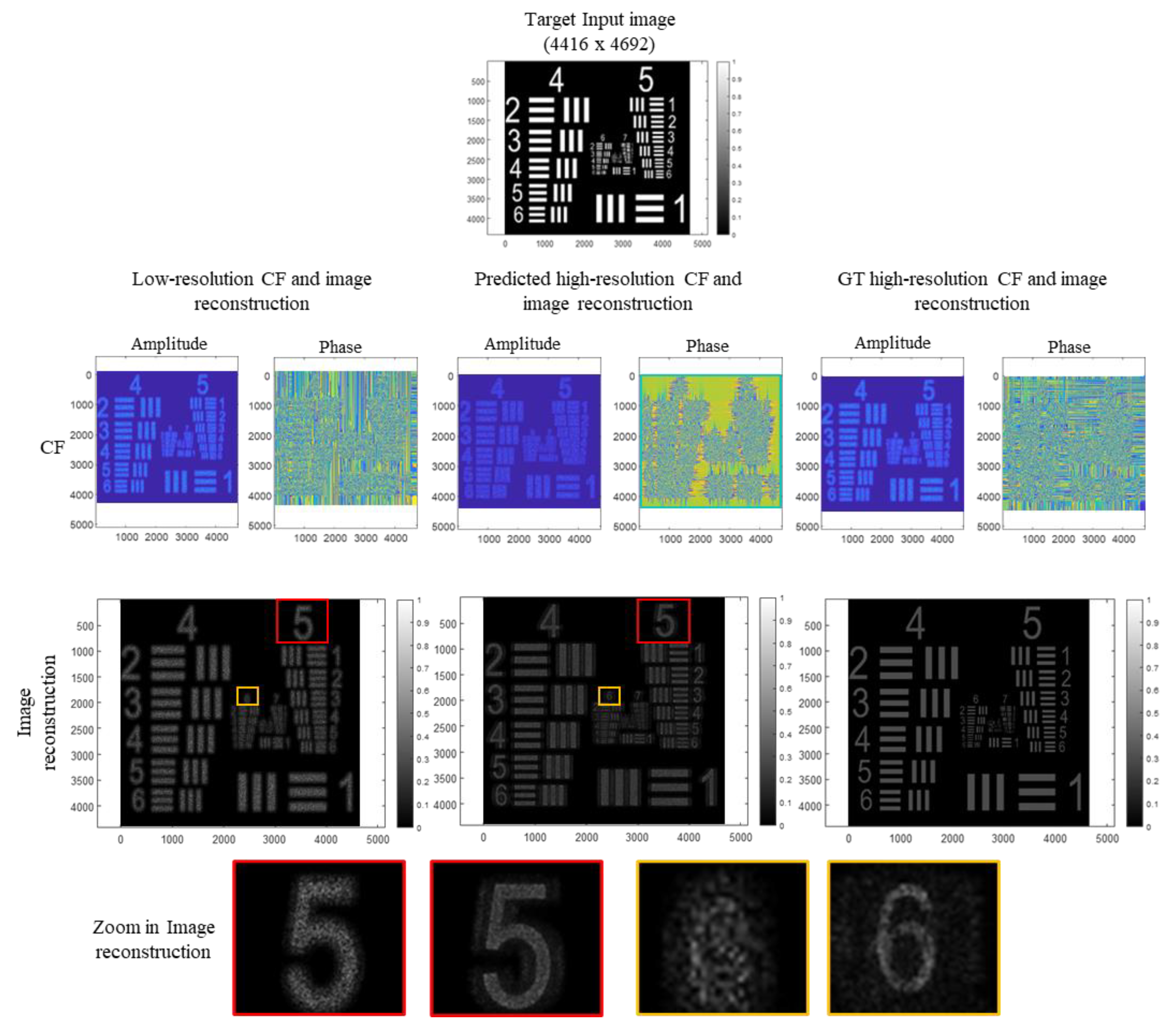
Figure 11 shows the simulation results for the USAF 1951 resolution test target image. In this simulation, the original image size is 4416 × 4692 pixels. We divide it into overlapping patches of size 128 × 128 pixels like the previous case. These patches slide over the input image, resulting in a total of approximately 72 × 72 patches being processed by the network. We observe that our proposed method significantly enhances the quality of the reconstructed images. We achieve improved image reconstructions by utilizing the network's high-resolution phase-shifted interference predictions to extract the complex field. This enhancement is particularly evident in the last row of Figure 11, which displays zoomed-in portions of the reconstructed images. The results demonstrate that our method effectively improves the clarity and detail in the reconstructed images, confirming its efficacy in enhancing image quality. Table 1 shows values for quantitative evaluation of low and predicted high-resolution reconstruction images presented in Figure 10 and Figure 11.
4. Conclusion
We have introduced a novel deep-learning technique for complex field extraction in holographic imaging that achieves resolution comparable to the native polarized image sensor. Utilizing a U-Net-based architecture, our method extracts complex field information directly at the hologram plane, which closely resembles the recorded interference pattern. This results in higher-quality extraction compared to methods that operate in the object plane and relies on four predicted high-resolution phase-shifted interference patterns generated by the network. The two key values of our proposed approach lie in the training strategy of network architecture. One is that it eliminates the need for numerical propagation when preparing the training dataset, making the network independent of specific propagation algorithms. This flexibility allows any numerical propagation method to be used post-extraction to reconstruct the object at different depths without DC and conjugate terms. Second, we simplify computational complexity and enhance efficiency by training the network with real-valued interference patterns and using only a single pair of low and high-resolution interference patterns for all examples. Also, our network demonstrates robustness to variations in random phase distributions and transverse shifts in the input patterns. In our future work, we plan to apply our proposed method to the experimentally captured data from image sensors with distinct polarization sensitivity. This will allow us to validate the effectiveness of our approach under real-world conditions and demonstrate its applicability in practical high-resolution holographic imaging systems. Overall, this method improves the quality of complex field extraction, offers greater flexibility, and increases efficiency in holographic image reconstruction, making it a promising solution for high-resolution holographic imaging applications.
Author Contributions
A.M.: methodology, software, data curation, formal analysis, writing—original draft; Y.L.: conceptualization, data curation, investigation; K.O.: software, validation, investigation; J.P.: conceptualization, methodology, investigation, supervision, writing—review and editing. All authors have read and agreed to the published version of the manuscript. .
Funding
Development of optical technology and sharing platform technology to acquire digital cultural heritage for high quality restoration of composite materials cultural heritage, Project Number: RS-2024-00442410.
Institutional Review Board Statement
Not applicable.
Informed Consent Statement
Not applicable.
Data Availability Statement
Data underlying the results presented in this paper are not publicly available at this time but may be obtained from the authors upon reasonable request.
Acknowledgments
This research was supported by Culture, Sports and Tourism R&D Program through the Korea Creative Content Agency grant funded by the Ministry of Culture, Sports and Tourism in 2024 (Project Name: Development of optical technology and sharing platform technology to acquire digital cultural heritage for high quality restoration of composite materials cultural heritage, Project Number: RS-2024-00442410, Contribution Rate: 100%).
Conflicts of Interest
The authors declare no conflict of interest.
References
- Nehmetallah, G.; Banerjee, P. P. Applications of Digital and Analog Holography in Three-Dimensional Imaging. Adv. Opt. Photon. 2012, 4 (4), 472–553. [CrossRef] . [CrossRef]
- Kim, M. K. Principles and Techniques of Digital Holographic Microscopy. SPIE Rev. 2010, 1 (1), 018005. [CrossRef]. [CrossRef]
- Deutsch, S. Holographic Imaging. IEEE Eng. Med. Biol. Mag. 2010, 29 (3), 82–84. [CrossRef].
- Rivenson, Y.; Wu, Y.; Ozcan, A. Deep Learning in Holography and Coherent Imaging. Light Sci. Appl. 2019, 8 (1), 85. [CrossRef] . [CrossRef]
- Zeng, T.; Zhu, Y.; Lam, E. Y. Deep Learning for Digital Holography: A Review. Opt. Express 2021, 29 (24), 40572–40593. [CrossRef] . [CrossRef]
- Wang, S.; Jiang, X.; Guo, H.; Wang, H. Improved SNR and Super-Resolution Reconstruction of Multi-Scale Digital Holography Based on Deep Learning. Opt. Commun. 2023, 129634. [CrossRef] . [CrossRef]
- Wu, Y.; Rivenson, Y.; Zhang, Y.; Wei, Z.; Gunaydin, H.; Lin, X.; Ozcan, A. Extended Depth-of-Field in Holographic Imaging Using Deep-Learning-Based Autofocusing and Phase Recovery. Optica 2018, 5 (6), 704–710. [CrossRef] . [CrossRef]
- Li, H.; Chen, X.; Chi, Z.; Mann, C. J.; Razi, A. Deep DIH: Single-Shot Digital In-Line Holography Reconstruction by Deep Learning. IEEE Access 2020, 8, 202648–202659. [CrossRef] . [CrossRef]
- Moon, I.; Jaferzadeh, K.; Kim, Y.; Javidi, B. Noise-Free Quantitative Phase Imaging in Gabor Holography with Conditional Generative Adversarial Network. Opt. Express 2020, 28 (18), 26284–26301. [CrossRef] . [CrossRef]
- Kreis, T. Digital Holographic Interference-Phase Measurement Using the Fourier-Transform Method. J. Opt. Soc. Am. A 1986, 3 (6), 847–855. [CrossRef] . [CrossRef]
- Yamaguchi, I.; Zhang, T. Phase-Shifting Digital Holography. Opt. Lett. 1997, 22 (16), 1268–1270. [CrossRef].
- Zhang, T.; Yamaguchi, I. Three-Dimensional Microscopy with Phase-Shifting Digital Holography. Opt. Lett. 1998, 23 (15), 1221–1223. [CrossRef]. [CrossRef]
- Awatsuji, Y.; Sasada, M.; Kubota, T. Parallel quasi-phase-shifting digital holography. Appl. Phys. Lett. 2004, 85, 1069–1071. [CrossRef] . [CrossRef]
- Novak, M.; Millerd, J.; Brock, N.; North-Morris, M.; Hayes, J.; Wyant, J. Analysis of a micropolarizer array-based simultaneous phase-shifting interferometer. Appl. Opt. 2005, 44, 6861–6868. [CrossRef] . [CrossRef]
- Liang, D.; Zhang, Q.;Wang, J.; Liu, J. Single-shot Fresnel incoherent digital holography based on geometric phase lens. J. Mod. Opt. 2020, 67, 92–98. [CrossRef] . [CrossRef]
- Wang, Z.; Han, B. Advanced Iterative Algorithm for Phase Extraction of Randomly Phase-Shifted Interferograms. Opt. Lett. 2004, 29 (14), 1671–1673. [CrossRef] . [CrossRef]
- Meneses-Fabian, C.; Rodriguez-Zurita, G.; Encarnacion-Gutierrez, M.-d.-C.; Toto-Arellano, N.I. Phase-shifting interferometry with four interferograms using linear polarization modulation and a Ronchi grating displaced by only a small unknown amount. Opt. Commun. 2009, 282, 3063–3068. [CrossRef] . [CrossRef]
- Gao, P.; Yao, B.L.; Min, J.W.; Guo, R.L.; Zheng, J.J.; Ye, T. Parallel two-step phase-shifting microscopic interferometry based on a cube beamsplitter. Opt. Commun. 2011, 284, 4136–4140. [CrossRef] . [CrossRef]
- Kakue, T.; Yonesaka, R.; Tahara, T.; Awatsuji, Y.; Nishio, K.; Ura, S.; Kubota, T.; Matoba, O. High-Speed Phase Imaging by Parallel Phase-Shifting Digital Holography. Opt. Lett. 2011, 36 (21), 4131–4133. [CrossRef] . [CrossRef]
- Wang, Y.; Meng, H.; Liu, X.; Liu, J.; Cui, X. Pixel Resolution Imaging in Parallel Phase-Shifting Digital Holography. Appl. Sci. 2022, 12 (12), 5812. [CrossRef] . [CrossRef]
- Tsuruta, M.; Fukuyama, T.; Tahara, T.; Takaki, Y. Fast Image Reconstruction Technique for Parallel Phase-Shifting Digital Holography. Appl. Sci. 2021, 11 (23), 11343. [CrossRef] . [CrossRef]
- Ju, Y.-G.; Choo, H.-G.; Park, J.-H. Learning-Based Complex Field Recovery from Digital Hologram with Various Depth Objects. Opt. Express 2022, 30 (15), 26149–26168. [CrossRef] . [CrossRef]
- Fang, X.; Tian, A.; Wang, S.; Zhang, R.; Wang, H.; Zhu, X. Parallel Phase-Shifting Digital Holographic Phase Imaging of Micro-Optical Elements with a Polarization Camera. Photonics 2023, 10 (12), 1291. [CrossRef] . [CrossRef]
- Liu, S.; Chen, J.; Xun, Y.; Zhao, X.; Chang, C.-H. A New Polarization Image Demosaicking Algorithm by Exploiting Inter-Channel Correlations with Guided Filtering. IEEE Trans. Image Process. 2020, 29, 7076–7089. [CrossRef] . [CrossRef]
- Xia, P.; Tahara, T.; Kakue, T.; Awatsuji, Y.; Nishio, K.; Ura, S.; Kubota, T.; Matoba, O. Performance comparison of bilinear interpolation, bicubic interpolation, and B-spline interpolation in parallel phase-shifting digital holography. Opt. Rev. 2013, 20, 193–197. [CrossRef] . [CrossRef]
- Lane, C.; Rode, D.; Rösgen, T. Calibration of a polarization image sensor and investigation of influencing factors. Appl. Opt. 2021, 61, C37–C45. [CrossRef] . [CrossRef]
- Millerd, J.; Brock, N.; Hayes, J.; North-Morris, M.; Kimbrough, B.; Wyant, J. Pixelated Phase-Mask Dynamic Interferometers. In Fringe 2005; Springer: Berlin/Heidelberg, Germany, 2006; pp. 640–647. [CrossRef].
- Gao, P.; Yuan, C. Resolution enhancement of digital holographic microscopy via synthetic aperture: A review. Light. Adv. Manuf. 2022, 3, 105–120. [CrossRef] . [CrossRef]
- Lee, S.; Nam, S. W.; Lee, J.; Jeong, Y.; Lee, B. HoloSR: Deep Learning-Based Super-Resolution for Real-Time High-Resolution Computer-Generated Holograms. Opt. Express 2024, 32 (7), 11107–11122. [CrossRef] . [CrossRef]
- Dong, C.; Loy, C. C.; He, K.; Tang, X. Image Super-Resolution Using Deep Convolutional Networks. IEEE Trans. Pattern Anal. Mach. Intell. 2016, 38 (2), 295–307. [CrossRef]. [CrossRef]
- Jee, M.; Kim, H.; Yoon, M.; Kim, C. Hologram Super-Resolution Using Dual-Generator GAN. Proc. 2022 IEEE Int. Conf. Image Process. (ICIP); IEEE: Piscataway, NJ, 2022; pp 2596–2600. [CrossRef].
- Ronneberger, O.; Fischer, P.; Brox, T. U-Net: Convolutional Networks for Biomedical Image Segmentation. Lect. Notes Comput. Sci. 2015, 234–241. [PubMed] . [CrossRef]
- Goodman, J.W. The Angular Spectrum of Plane Waves. In Introduction to Fourier Optics, 2nd ed.; Director, S.W., Ed.; McGraw-Hill: New York, NY, USA, 1996; pp. 55–61.
Figure 2.
Decimation and interpolation scheme used in the training stage of the proposed method. The equation for the calculation of complex fields for the respective set of interference patterns is indicated below each group.
Figure 2.
Decimation and interpolation scheme used in the training stage of the proposed method. The equation for the calculation of complex fields for the respective set of interference patterns is indicated below each group.
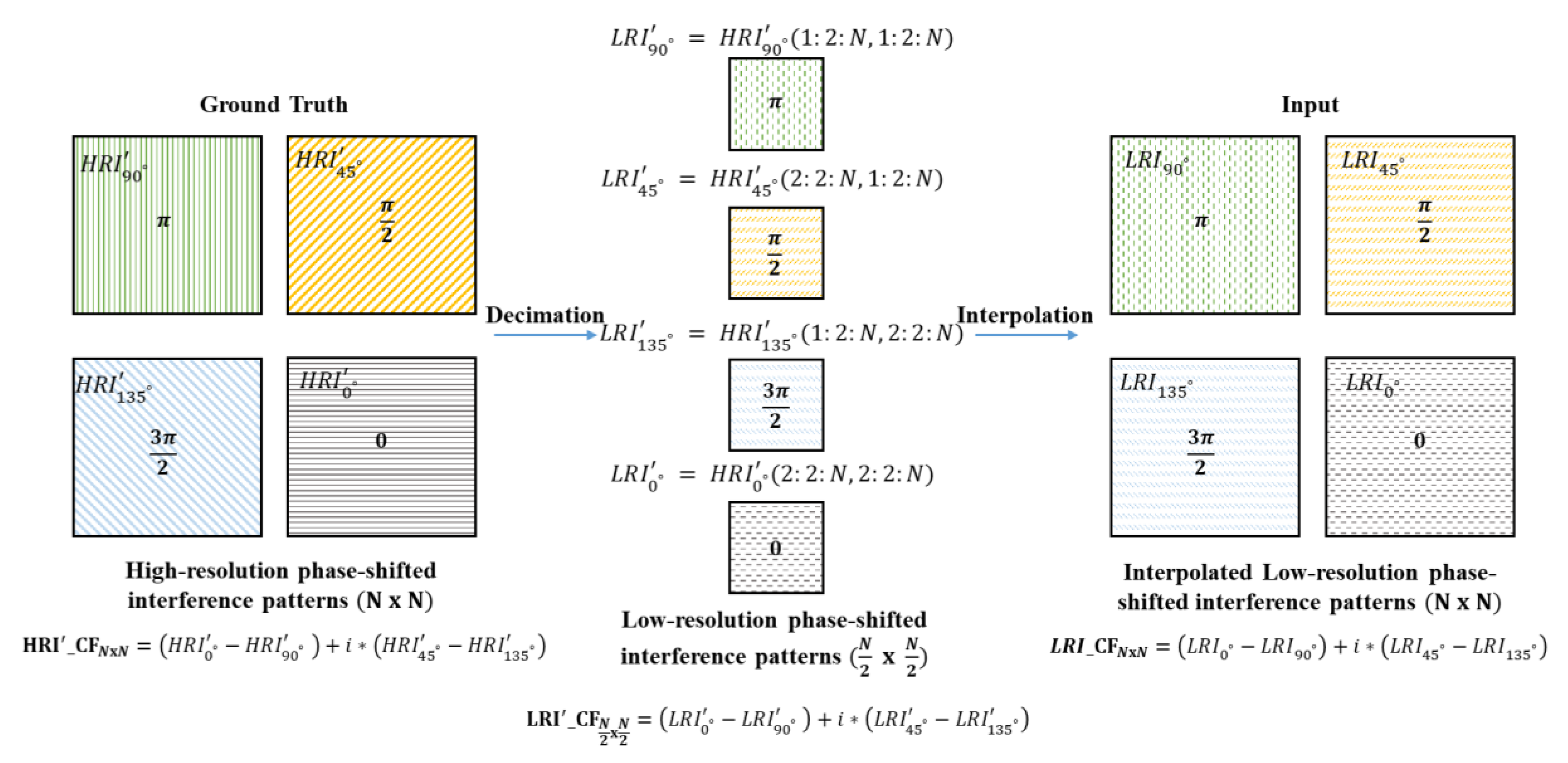
Figure 3.
Generation flow of training input and ground truth data.
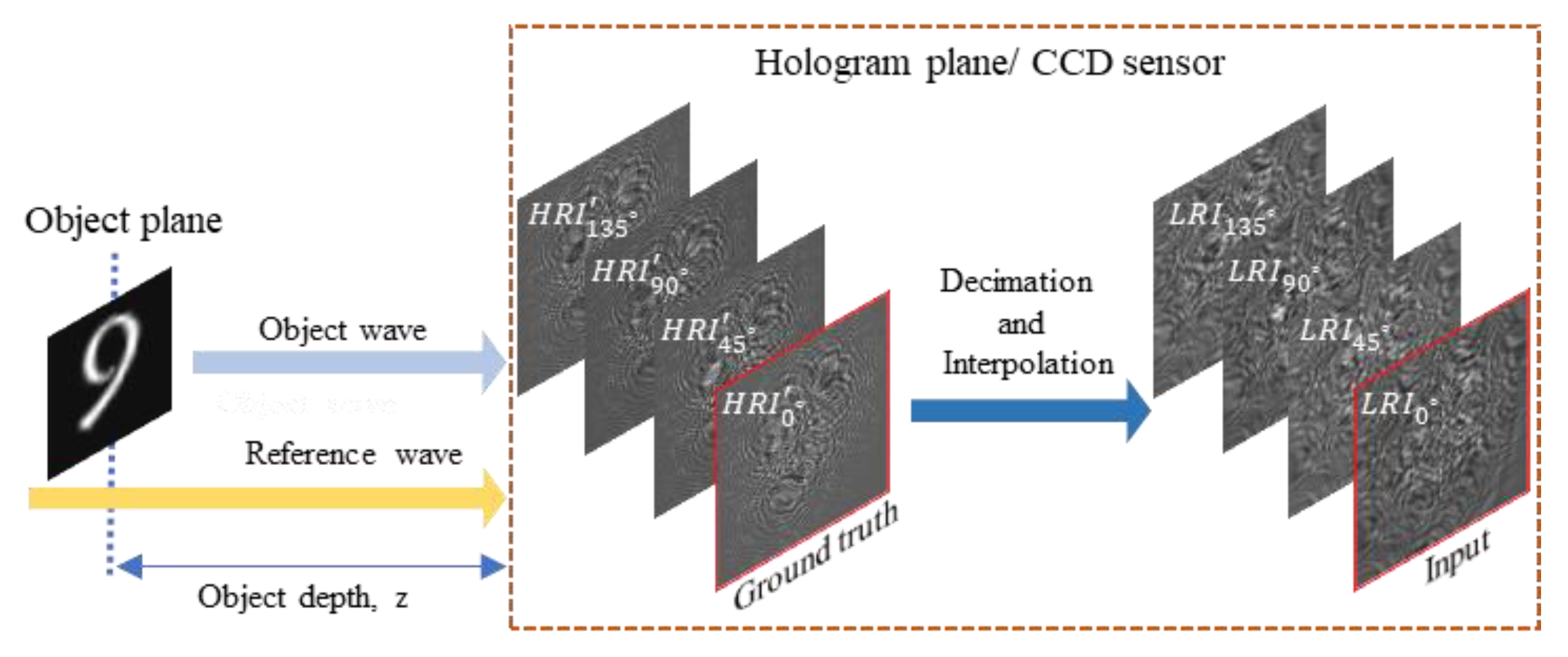
Figure 4.
U-Net-based regression network architecture.
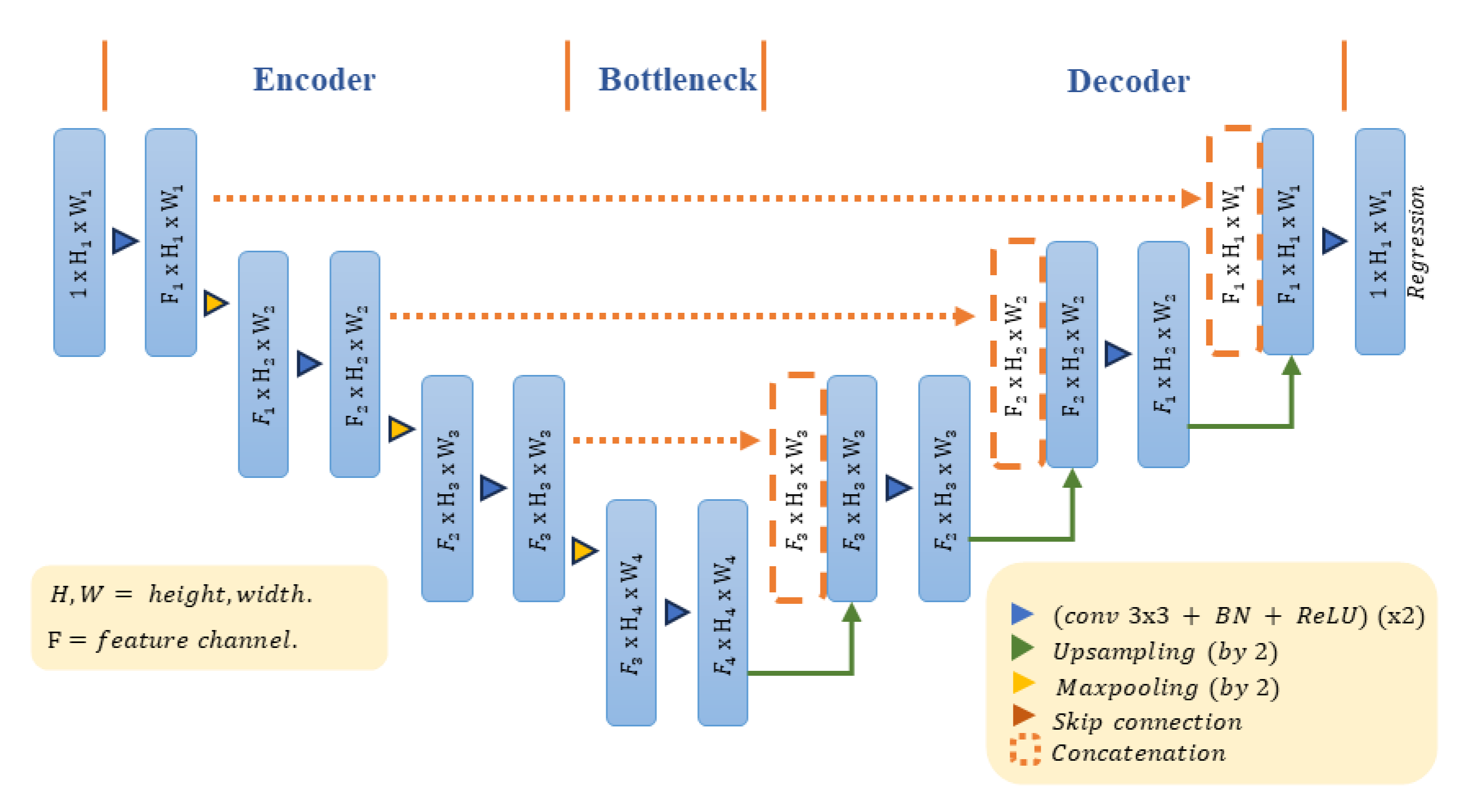
Figure 5.
(a) Training stage: A single image pair of low and high resolution from the training dataset is used. (b) Prediction stage: the same network is used to predict all four HR interference patterns. .
Figure 5.
(a) Training stage: A single image pair of low and high resolution from the training dataset is used. (b) Prediction stage: the same network is used to predict all four HR interference patterns. .
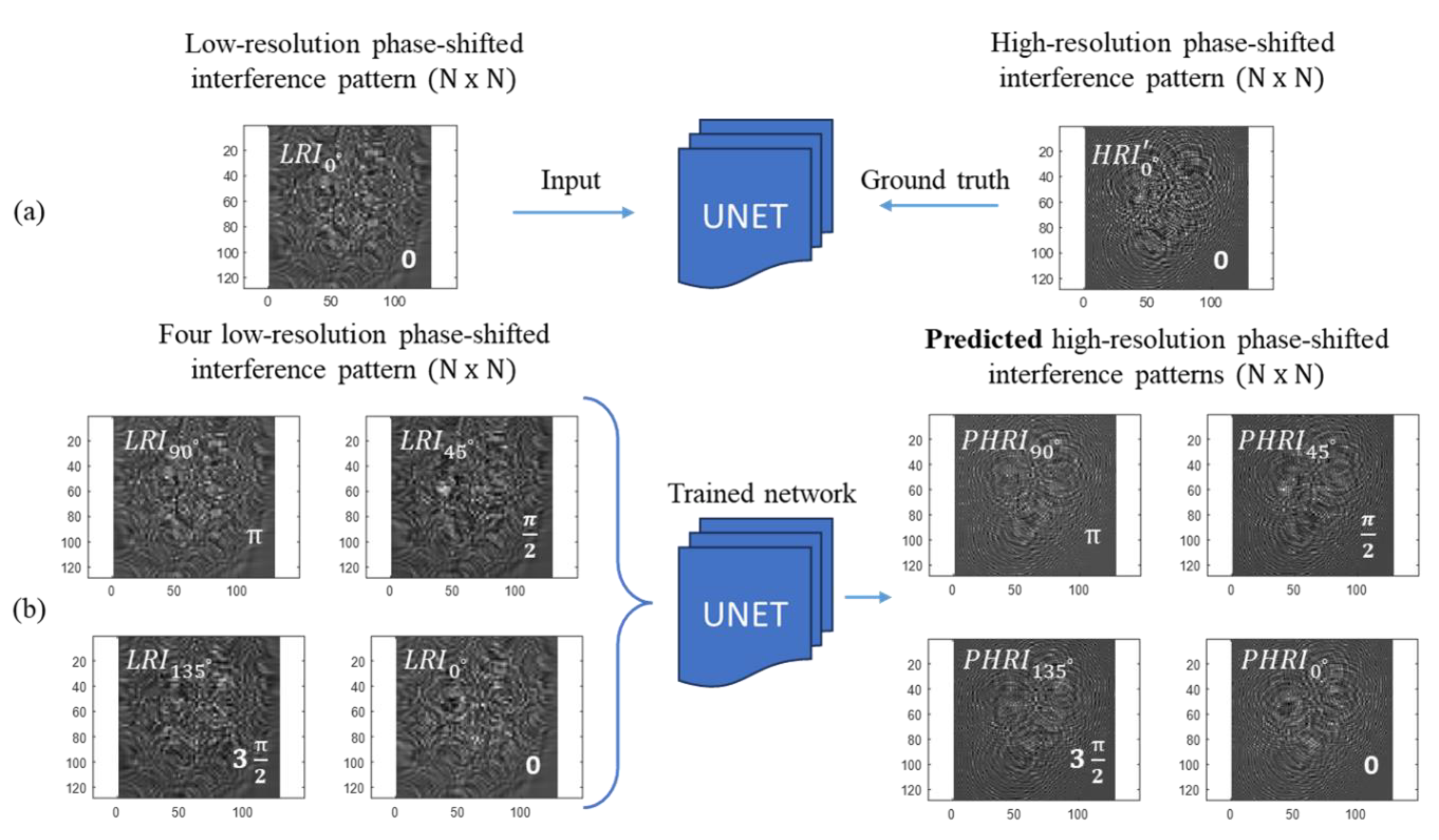
Figure 6.
Amplitude and phase representation of complex field calculated from low, predicted and high-resolution phase-shifted interference patterns.
Figure 6.
Amplitude and phase representation of complex field calculated from low, predicted and high-resolution phase-shifted interference patterns.
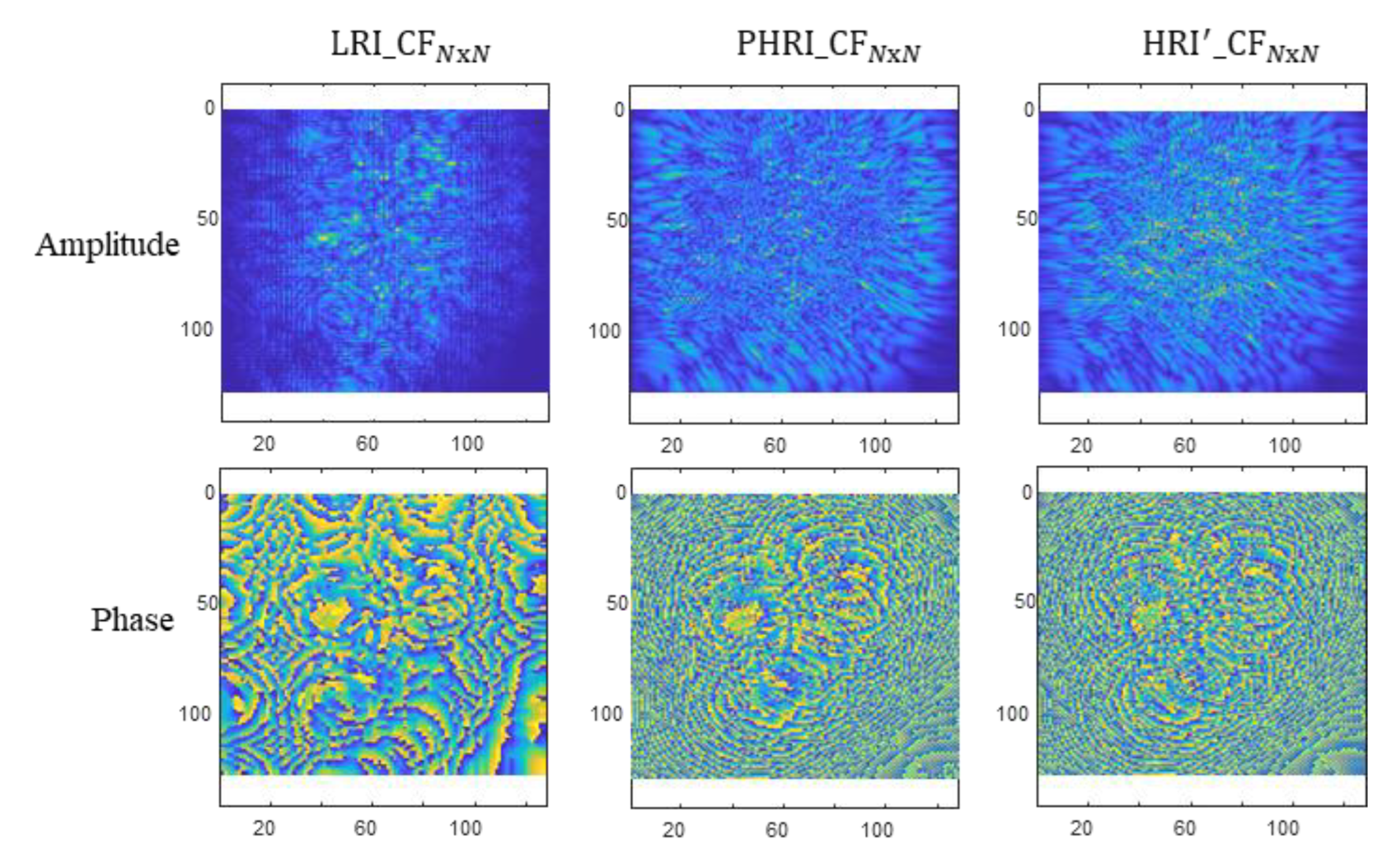
Figure 7.
Low, predicted, and high-resolution zero phase shifted interference patterns with (a) different random phase distribution and (b) different transverse shifts applied to the same target image.
Figure 7.
Low, predicted, and high-resolution zero phase shifted interference patterns with (a) different random phase distribution and (b) different transverse shifts applied to the same target image.
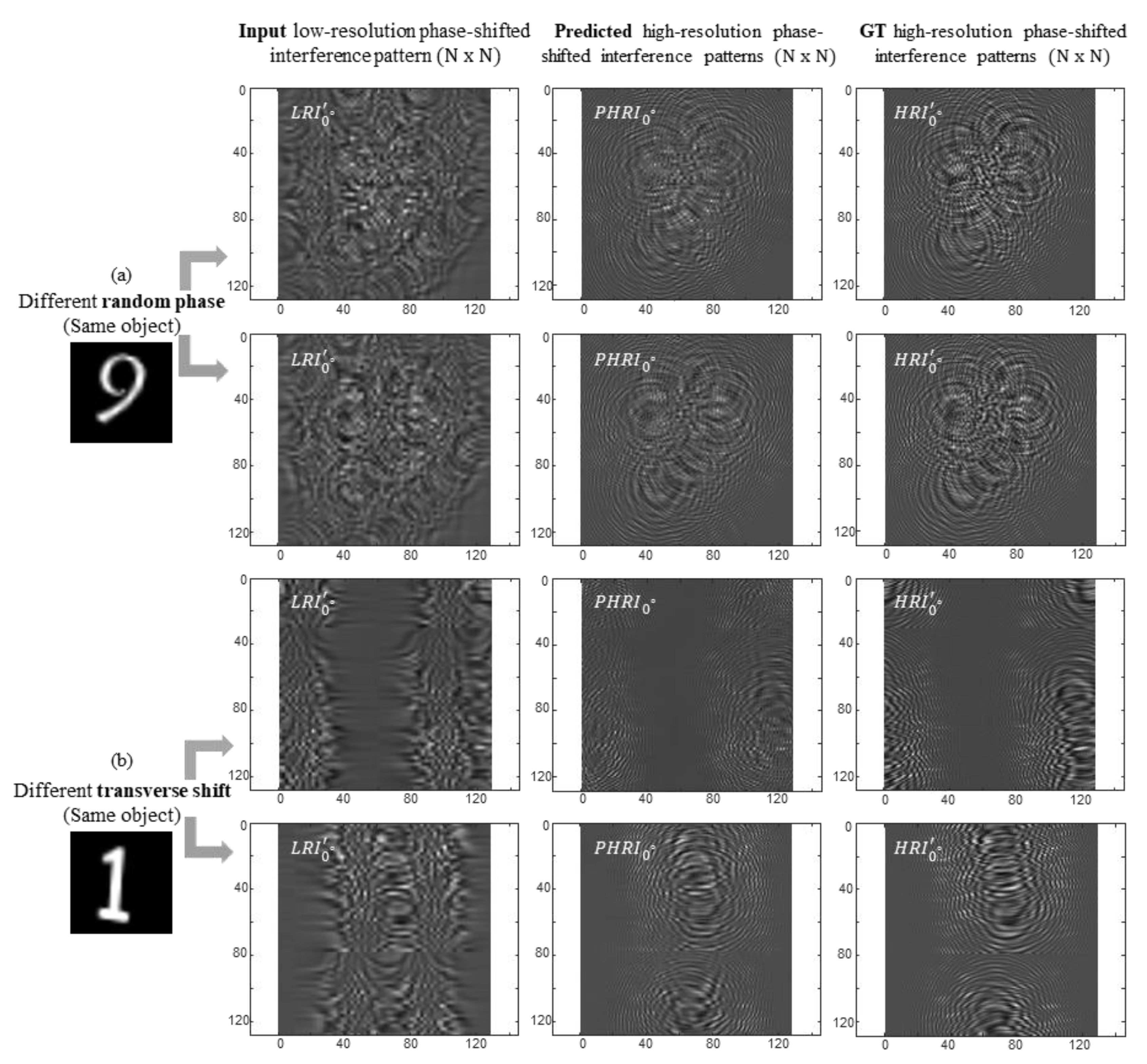
Figure 8.
Amplitude and phase of the object’s complex field and its image reconstruction in the following row for two test images in (a) and (b), and a comparison between low, predicted and high-resolution image reconstruction using the proposed method.
Figure 8.
Amplitude and phase of the object’s complex field and its image reconstruction in the following row for two test images in (a) and (b), and a comparison between low, predicted and high-resolution image reconstruction using the proposed method.
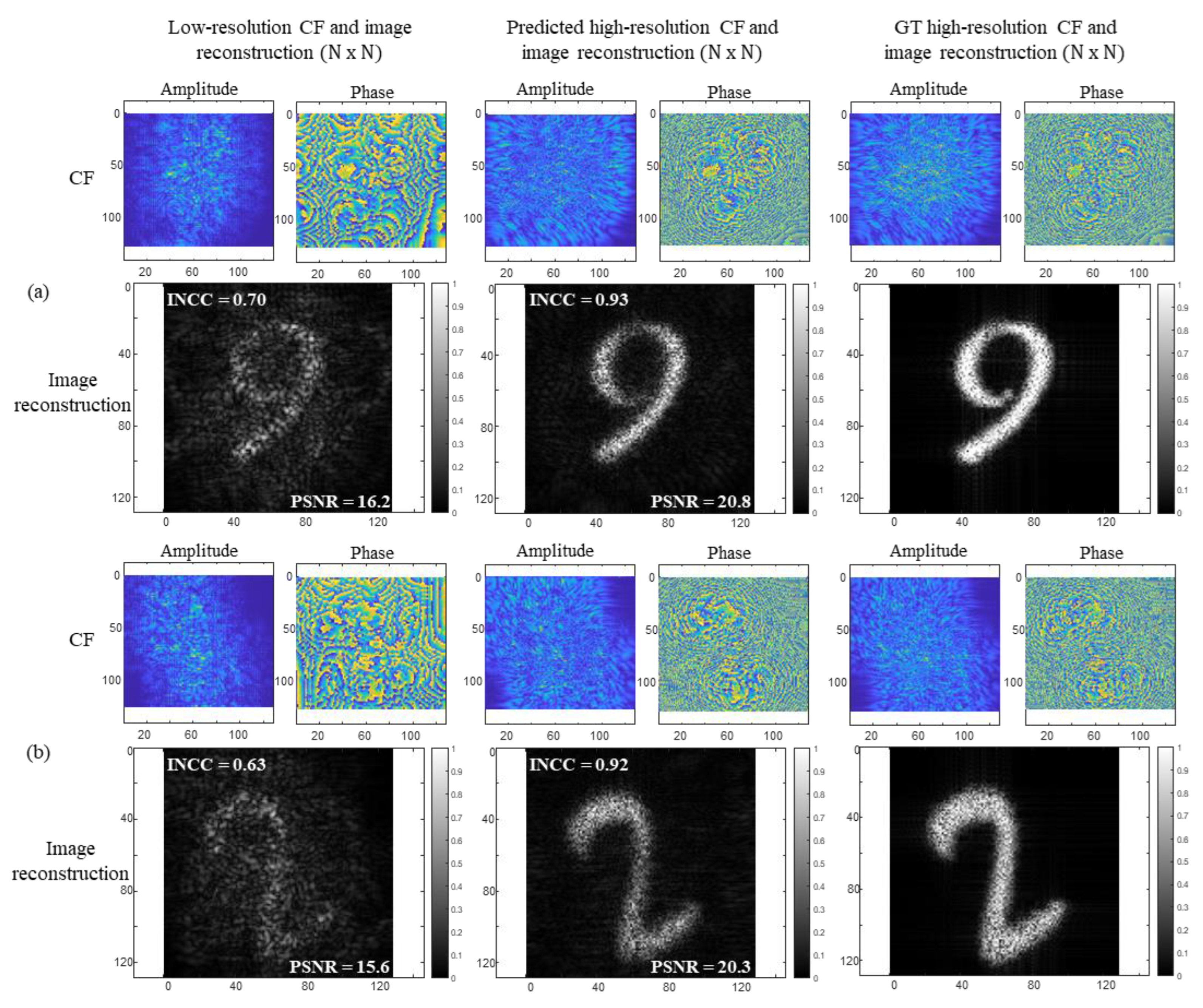
Figure 9.
Image reconstruction at different depths from the hologram plane for low, predicted and high-resolution complex field information.
Figure 9.
Image reconstruction at different depths from the hologram plane for low, predicted and high-resolution complex field information.
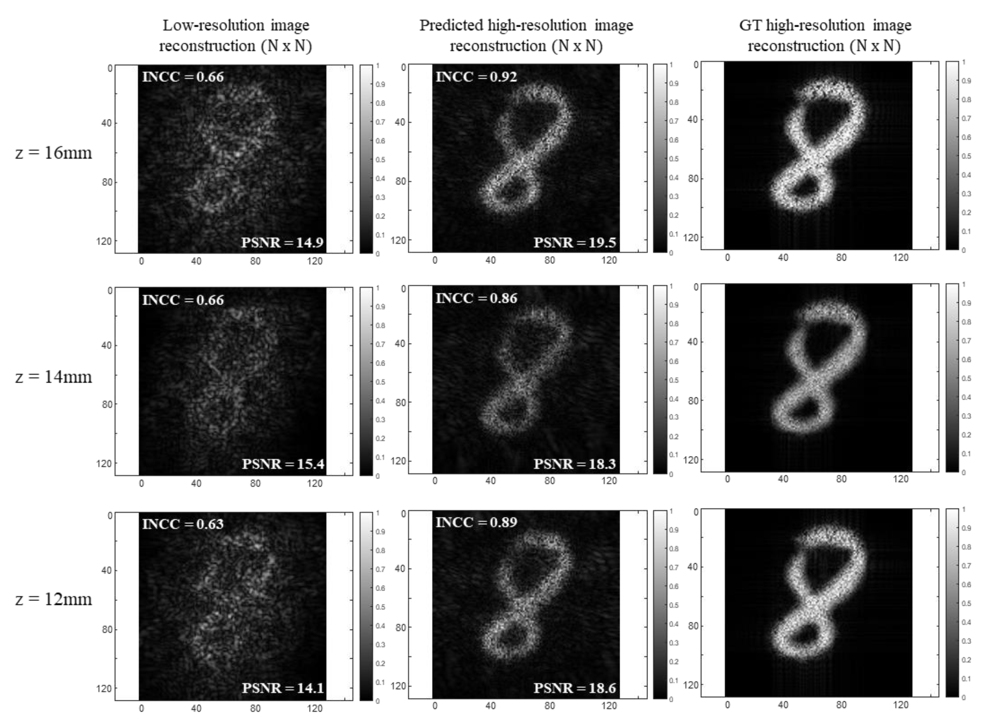
Figure 10.
Amplitude and phase of the object’s complex field and its image reconstruction in the following row for larger input image size generated from the FMNIST dataset and a comparison between low, predicted and high-resolution image reconstruction using the proposed method.
Figure 10.
Amplitude and phase of the object’s complex field and its image reconstruction in the following row for larger input image size generated from the FMNIST dataset and a comparison between low, predicted and high-resolution image reconstruction using the proposed method.
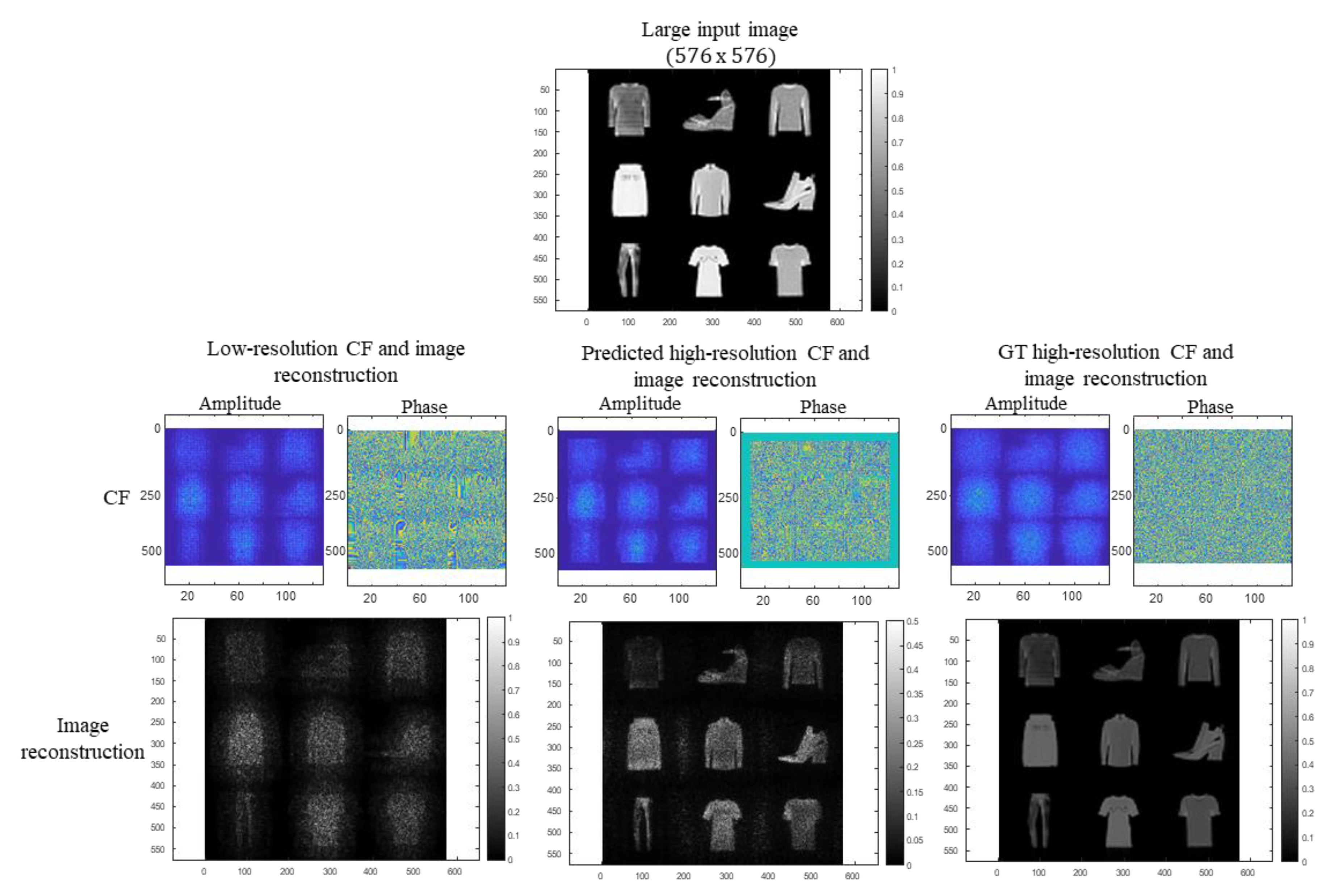
Figure 11.
Target input image in the first row of size 4416 x 4692. Amplitude and phase of the object’s complex field and its image reconstruction in the following row for USAF target resolution generated, and a comparison between low, predicted and high-resolution image reconstruction with zoomed-in boxes in red and yellow for better visualization in the last row.

Disclaimer/Publisher’s Note: The statements, opinions and data contained in all publications are solely those of the individual author(s) and contributor(s) and not of MDPI and/or the editor(s). MDPI and/or the editor(s) disclaim responsibility for any injury to people or property resulting from any ideas, methods, instructions or products referred to in the content. |
© 2024 by the authors. Licensee MDPI, Basel, Switzerland. This article is an open access article distributed under the terms and conditions of the Creative Commons Attribution (CC BY) license (http://creativecommons.org/licenses/by/4.0/).
Copyright: This open access article is published under a Creative Commons CC BY 4.0 license, which permit the free download, distribution, and reuse, provided that the author and preprint are cited in any reuse.


