Submitted:
16 November 2024
Posted:
18 November 2024
You are already at the latest version
Abstract
Computer modeling of the construction and operation of technical structures is increasingly done using software that includes more detailed knowledge, which requires an increase in the level as well as an expansion of the scope of the geometric knowledge. A significant part of the motion transmission mechanisms are the worm drive pairs, for which the separation of the parts dealing with the theoretical and practical problems found in the literature can be experienced in numerous instances. Due to the different technical features, in many cases the screw surfaces are not designed and manufactured in a geometrically correct way, or the best solution is not necessarily chosen. The geometric model describing the production process of the screw surfaces provides the basis for examining the deviation between the surface mathematically determined by the designer and the surface produced. An integrated mathematical kinematic model was developed for the production geometrical analysis of the elements of cylindrical and conical worm gear drive pairs for machining with a traditional thread grinding machine, which causes a serious pitch fluctuating error among several other problems in case of machining the conical worm. During the geometrical research of production modelling, running parallel to the analysis of these errors, the idea was formulated, since the geometric modelling always is created with the toolbox of descriptive geometry, in which the application of projective invariants proves useful in many cases, it may be advisable to create a projective relationship between the reference surfaces of conical and cylindrical spiral surfaces. As a result of the research conducted for the mathematical generalization of the integrated model, the improved constructive geometric model was created, in which the method of analytically creating the projective geometric relationship between the reference surfaces of conical and cylindrical helicoid surfaces has been described for the first time in this article. The significance of the further development presented in this article is that during the production of the conical helicoid surface, the thread pitch fluctuation has been eliminated, and that the algebraic form of the central collineation relationship between the reference surfaces of the conical and cylindrical worms has also been determined. In accordance with the improved constructive geometric model, the technological environment and tools must be rearranged and relocated during further work.
Keywords:
worm gear drives
; constructive geometric model
; generalization
; homogeneous normalized coordinate
; central collineation
1. Introduction
The structure construction of technological constructions [1] and motion transmission mechanisms [2], the analytical determination of their operation [3] and their computer modelling [4] are always done with the abstractions of descriptive geometry [5]. In the same way that the importance of mathematical proficiency increases with the computerization of calculation procedures [6,7,8], higher-level descriptive geometry skills are also needed to operate increasingly sophisticated modelling software [9,10,11]. Drawing the 3D presentations by any computer added design program has made the learned theories and constructions of Monge’s approach irreplaceable [12]. Knowledge of Monge's concept allows us to recognize metrical relationships in space and gives us the freedom to select between different visualization possibilities [13].
Mathematics reveals many geometries for abstractly describing physical phenomena [14,15], solving various tasks, and handling emerging problems [16,17]. There are many examples of how, as long as the plan of buildings [18], the design of mechanical motion transmission structures [19] and their control measurements [20] are made in the Euclidean spatial model, it is possible to reach from one point on Earth to another point using spherical geometry [21]. In the examination of the laws of eye imaging, the laws to which references are created, belong to geometry in the traditional sense, but at the same time, distances and angles do not remain constant during the central projection as a transformation [22]. Accordingly, in the case of central projection, the laws of classical geometry cannot be applied. During the work of Szabó and Kunkli as a joint geometric researcher, in one of their articles they show how, along the lines of Szabó's earlier theorems, given certain data, it is possible to generate an image obtained by a central projection from a photograph of a photograph, which in most cases is no longer a central projection, by applying a well-chosen affinity [23]. In the case of the application of perspective, it is naturally offered to supplement the plane with an infinitely distant straight line, and the space with the infinitely distant plane. The geometry that best models reality should always be used to solve the actual problem.
One of the most salient essential points of the Erlangen program is that every geometry is the theory of the invariants of an algebraic transformation group, and vice versa, that every algebraic transformation group has a geometry [24]. The study of the invariants of the transformation group of geometry is geometry itself [25]. According to the algebraic group of transformations of geometry, two geometric shapes are equivalent if one shape can be transformed into the other using one of the algebraic group of transformations. According to the all this, Euclidean geometry is a particular case of projective geometry [16], and projective geometry is a generalisation of Euclidean geometry that includes the Euclidean geometric system.
In addition to having significant in the realistic planar representation of spatial objects, synthetically formed projective geometry has a strict logical structure. The study of this rigorous logical structure has been presented in an article from that point of view that it could even be a model of Hegelian logic according to certain aspects [26]. The basic means of analytically further developed projective geometry are homogeneous coordinates and linear transformations, the knowledge of which is essential for computer graphics [27].
For all these reasons, the knowledge and study of projective geometry is a prerequisite for computer modelling and graphics research [28].
A practical solution for the visual representation of the conscious geometric structure of spatial objects based on strict mathematical foundations and logic are computer-enhanced descriptive geometry (CeDG), which is a scientific approach to the computerization of three-dimensional (3D) geometric systems using descriptive geometric procedures, which is compatible with today's technological conditions for modelling. One contribution to the science field is the timeless geometric approach in a timely way that guarantees mathematical precision with a timely method by inheriting the laws of projective geometric invariants bearing the signs of symmetric duality [29].
In addition to displaying the spatial motion-transmitting drive pairs, the basis for creating a model suitable for characterizing relative motions is also descriptive geometry [30]. Geometrical modelling of the technological processes that correspond to reality is essential for the correct examination of motion transmission mechanisms. The mathematical developments and abstractions developed by us are determined by whether our created abstraction describes the operation of the investigated technology. The topics of the mathematical developments are always determined in parallel with the direction of technological development.
In many cases, the mathematical definition of a complex surface has been differed from the surface created by machining. The differences are caused mainly by the surface of the machining tools created by the technological environment and the real practicable path of movement that can be created. The simultaneous examinations of the geometry and the trajectory of the tool are the mathematical basis of several engineering research works [31,32]. This is also the case with the working surfaces of cylindrical or conical screws, namely the defined helicoid surface differs from the surface machined at the existing technological conditions. The integrated model [33] was developed to analyze these deviations. For the production geometric analysis and development of the elements of the conical and cylindrical worm gear drives, the coordinate systems extended with the geometrical parameters are shown in Figure 1, prepared for the traditional thread grinder.
The applied coordinate systems of the integrated mathematical kinematical model:
- -
- K0 (x0, y0, z0) the stationary coordinate system of the machining machine tool,
- -
- K1 (x1, y1, z1) the coordinate system fixed to a linearly moving table,
- -
- K1F (x1F, y1F, z1F) the rotating coordinate system affixed to the helicoidal surface determined by parameters η and ϑ ,
- -
- K2 (x2, y2, z2) the stationary coordinate system attached to the tool or gear,
- -
- sub>- K2F (x2F, y2F, z2F) the rotary coordinate system fixed to the tool or gear with axis z2F,
- -
- K20 (x20, y20, z20) the coordinate system of the generating curve of the tool surface,
- -
- Kk (xk, yk, zk) the auxiliary coordinate system,
- -
- O0, O1, O2, O1F, O2F, Ok the origins of coordinate systems according to their subscripts.
Based on the literature [33], the geometric parameters used in the integrated mathematical kinematic model are as follows
- -
- a y-direction coordinate of the starting point 02 of the tool coordinate system in the stationary coordinate system Ko, namely the center distance [mm],
- -
- c the x coordinate of the origin 02 of the tool's coordinate system in the stationary coordinate system K0, the value of tool displacement (e.g. the radius of the dedendum cylinder or base cylinder in the case of a convolute or involute worm) [mm],
- -
- αo tilting angle of the tool into the profile of the helicoidal surface in the characteristic section [°],
- -
- γo= γ lead angle of worm’s reference surface [°],
- -
- po= p pitch on the reference surface of the worm [mm],
- -
- pa screw parameter in the axial direction [mm],
- -
- pr screw parameter in the radial direction [mm],
- -
- φ1 angle of rotation of helical surface (enveloping, movement parameter) [°],
- -
- φ2 angle of rotation of the tool (enveloping, movement parameter) [°],
- -
- ω1 angular velocity of the worm [s-1],
- -
- ω2 angular velocity of the tool [s-1].
The zF1 is the axis of cylindrical worms or hobs, or the adjusted z1F is the axis of conical worms or hobs, and the zF2 is the axis of wheels or tools of worms. The developed integrated model is also suitable for the analysis of the properties of worm gear drives in the case of the axis angle chosen as .
Conical and cylindrical helicoid surfaces are machined on the traditional thread grinder, on the common generatrix of the reference surfaces adjusted to the path of the grinder, according to the scheme of the integrated model. For this, it is necessary that the reference cone is tilted with its half-opening angle to the generatrix of the reference cylinder lying on the tool path, namely the conical helicoid surface is machined with axis displacement, as it is shown in Figure 2.
In this arrangement, the conical worm with an adjusted axis is driven through a lathe dog driven by a drive pin. The contact of the reference surface of the adjusted conical worm with the grinding wheel has been taken on the ellipse path of a cone, therefore the changing radius relative to the axis of the conical worm creates a pitch fluctuation. Eliminating these challenges of the thread pitch fluctuation, the determination of the profile of the drive pin has been counted in an explicit form with the use of expediently chosen descriptive geometric projections and the use of inherited projective invariants, if a point contact has been considered between the lathe dog and the drive pin [34].
The elimination of this challenge in a natural mathematical way was one of the reasons for the creation of the improvement presented here, according to which the reference surfaces of the worms are placed on a common axis instead of the common generatrix.
Another main reason for the development presented in this article is the case of the special matrix representation of the coordinate transformation applied in gear theory [35]. In many cases of mechanical engineering activities, the special case of matrix representation of coordinate transformations is used, namely with the applicate of a 4x4 matrix, the new Cartesian coordinates of a point can be expressed with the old Cartesian coordinates as follows
where the submatrix is the matrix of rotation around an axis, and is the displacement vector of the starting point of the coordinate system. An analytical form of Euclidean geometry interpreted as a special case of projective geometry is used during the geometric modelling of the motion-transition drive pairs [16]. Looking for the possibility of further development of the integrated mathematical kinematic model, the possibility of extending it to the projective space characterized by homogeneous coordinates was examined.
During the further development of the manufacturing geometry of the conical and cylindrical helicoidal surfaces, the need arose for the matrix algebraic formulation of the relationship between the reference cone and the reference cylinder surfaces, which later aimed to unify the testing method of their machining tools.
In this publication, the method of creating process of the transformation relationship between the reference surfaces interpreted in the projective space model, which has not been published until now, is presented.
2. Constructive Geometric Model Created as a Further Development of the Integrated Model
In the literature created for contact analysis of the cylindrical and conical worm gear drive pairs and the development of the production geometry of that drive pair elements, often there was a separation of the theoretical discussion and practical problems, so to solve which the integrated model was developed [33]. The constructive geometric model is a further mathematical generalization of this integrated model, which has been created to examine the cylindrical and conical worm gear drives and develop the production geometry of these drive pairs elements.
In the constructive geometric model, as indicated by arrows in Figure 3, the axis of the conical helicoid has been adjusted to the axis of the cylindrical helicoid with the aim of writing the central collineation relationship between their reference surfaces. The relationship between the coordinate systems used in the constructive geometric model and the geometric parameters for the production geometrical examination of the cylindrical or conical worms or hobs on the common zF1 axis, as well as the gears or worm machining tools located on the zF2 axis, are also shown in Figure 3.
In the constructive geometric model, the geometrical analyses of machining are made using an analytical form of Euclidean geometry interpreted as a special case of projective geometry [16].
2.1. Analytical Aspects of the Projective Geometry Applied During the Extension of the Model
This subsection provides a brief overview of the applied parts of projective geometry in elaborating of the scientific development. In case of the analytical definition of the Euclidean space model, three real Cartesian coordinates are assigned to the points, which are used to determine the homogeneous coordinates of the points with the following identities
so then
and vice versa in case based on (1)
Two homogeneous coordinate quadrilaterals define the same point if and only if the corresponding homogeneous coordinates are products of each other by the same scalar.
In the case of the form of a homogeneous coordinate quadrilateral
since , the point must be interpreted at an infinite distance in the Cartesian coordinate system in the direction defined by (x1, x2, x3). In the following the homogeneous coordinates of point P can also be written in the shorter form where . Each plane S of space can be assigned an ordered quadruple consisting of real numbers , for which
namely a quadruple consisting of all zeros cannot characterise a plane.
Two planes are identical if and only if their respective coordinates are multiples of each other with the same scalar number.
In space, a straight-line is defined as the intersection of two planes. The analytical form of the intersection line is done with a matrix consisting of eight real numbers of the two planes in the following way
where one plane is defined by the quad of numbers and the other plane is defined by the quad of numbers , which is in short, if α=1,2 .
A point lies on the straight line α=1,2, or in other words the line passes through on the point f and only if the point P lies on the two planes defining the line, namely
or in short
The projective point transformation is a linear mapping in which the fit of the space elements and the cross ratio of the four points of a line are invariant.
The projective point transformation that maps the points of the 3D space to the points of the 3D space, bijectively maps four non-coplanar points to four non-coplanar points. This special point transformation can be given by a 4×4 regular matrix in the following form
where .
Theorem 1.The set of projective point coordinate transformations to carry out the transformations after each other, which is a transformation, which is an operation, forms a group of projective transformations.
Proof of Theorem 1. The transformation should be given in matrix form in the following form
where .
By performing two projective transformations one after the other can be written in the following forms
following forms and
where .
Due to the previous equalities
in which the is also regular matrix from the multiplication theorem of the determinants.
Successive execution of projective transformations has associativity due to the similar property of regular matrices.
There is a unit transformation, which can be given with the unit matrix and its effect is identity.
Every transformation has an inverse, and if the original transformation is C described with a matrix, then this is given by the inverse matrix C−1, and its existence is given by C ensures its regularity. □
Definition 1. In the projective space, the set of points whose homogeneous coordinates fulfil the equation
creats a second-order surface.
Defintition 2. The matrix formed from the coefficients in the equation of the second-order surface is called the basic matrix of the surface.
The matrix of the second-order surfaces is symmetric, or can be transformed into a symmetric matrix by projective transformations, in which the diagonal has only +1, -1 or 0 by successive application of projective transformations, which is called the normalised form of the matrix.
Defintition 3. The range of the matrix of the second-order surface is the sum of the number of coefficients +1 and -1 in the matrix‘s normalised form, which is denoted by R.
Defintition 4. The signature of the matrix of the second-order surface is the difference of the number of coefficients +1 and –1 taken in absolute value in the matrix‘s normalised form, which is denoted by S.
The range and signature of the matrix of the second-order surface are invariant when the projective transformation is performed, so the classification of second-order surfaces has been always performed in a coordinate system in which the surface can be written in normal form, and the classification is based on the R rank and S signature. Cones and cylinders belong to the same class of second order surfaces when the cases R=3 and S=1 occur.
2.2. The Method for Creating a Relationship Between the Reference Surfaces of the Worms
In the constructive geometric model created for the production geometry development of conical and cylindrical worm gear drive pairs, the reference surfaces of the worms are placed according to Figure 4.
The further developed constructive geometric model the reference surfaces of the conical and cylindrical worms, exactly the rotation cone and cylinder with their axes lying on the z1F coordinate axis, provide the possibility to create a central collineation relationship.
During the development of the constructive geometry model, the vertex Mk of the rederence cone was placed at the origin O1F of the K1F coordinate system to facilitate the procedure of the creation of the relationship between the reference cone and the reference cylinder.
The cone vertex Mk and the cylinder vertex Mh∞ with an infinite distance on the axis z1F are correspond to each other. The fix plane As is the plane of the common circle of the reference cylinder and the reference cone. Furthermore, the center C of the central collineation is any point on the z1F axis with homogeneous coordinates C(0, 0, c, 1) in such a way, that the center C can be any point on the axis z1F except for the cylinder and cone vertices as well as the point lying on the fix plane As. The arranger straight passing through the point Ph of the cylinder surface and the collineation center C intersects the cone surface at the point Pk. The point Ph and the point Pk could be assigned to each other in the central collinear relationship. Those arranger straight lines lying at the center point C, which are parallel to the cone generator straight lines, intersect the cylinder at the points of the circle, which points are located on the plane Eh parallel to the fixed plane As.
During the central collineation mapping, the points of the Eh plane are transformed into points in infinity, namely disappear into infinity, which is why it is called the vanishing plane. The vanishing plane Eh is as far from the center C as the vanishing plane Ek of the cone is from the fix plane As. As shown in Figure 3, the half-opening angle of the right circular cone is the angle δ1. The height of the cone between the fixed plane As and the vertex Mk is denoted by m. The radius of the common circle of the right circular cylinder and the right circular cone lying on the fix plane As is denoted by r. The radius of the circle of the point Pk lying on the cone is denoted by R. In the normed homogeneous Cartesian coordinate system, the coordinates of the points of cylinder (marked by xI and xK) completes the following relation
which can also be written in the matrix format as follows
In the case of calculations with coordinates, it is advisable to write the matrix format with the coordinates in the following way
In the normed homogeneous Cartesian coordinate system, the coordinates of the points of cone (marked by xI and xK) completes the following relation
which can also be written in the matrix format as follows
In the case of calculations with coordinates, it is advisable to write the matrix format with the coordinates in the following way
where
which means in the constructive geometrical model
is clearly fulfilled. □
2.2.1. Determination of the Transformation Matrix of the Mapping of the Conical Worm Reference Surface to the Cylindrical Worm Reference Surface
Based on the similar triangles that arise in the case of the placement outlined in Figure 3, it can be determine the following relationships
from which the parameter u can be expressed as follows
The z coordinate of the point Ph of the reference cylinder can be determined basing on the relationships shown in Figure 3
The Table 1 shows the corresponded points between the reference surfaces of the worms, which had been applied in the procedure to determine the matrix that produces the surface point of the cone.
It is known that every point is also characterized by a non-zero scalar multiple of its homogeneous coordinates. For defining the matrix of the cone, the points were mapped to the points of the cone, whose homogeneous coordinates must be chosen such that the sum of the corresponding coordinates of the first four points is the corresponding coordinates of the fifth point to be. The values of the scalars λ1, λ2, λ3 and λ4 must be determined accordingly, namely
The coordinates of the point Pk are determined as a result of the solutions of the system of equations, relating to the proportionality factors as unknowns summarized in Table 2.
The columns of the matrix of the transformation have been formed by the values of the homogeneous coordinates multiplied by , namely after the appropriate transformations
The coordinates of the point Ph are determined as a result of the solutions of the system of equations, relating to the proportionality factors as unknowns summarized in Table 2. The coordinates of the point Pk are determined as a result of the solutions of the system of equations, relating to the proportionality factors as unknowns summarized in Table 3.
The columns of the matrix of the transformation have been formed by the values of the homogeneous coordinates multiplied by , namely
The matrix of the central collineation can be created from the combination of the U and T matrices, thus the matrix of the transformation from the reference cone surface to the reference cylinder surface with the following relation
The determinant of the U matrix required to determine the , which can be given in the following form
The inverse of matrix U has been determined using the following relationship
where refers to the adjoint of a matrix U. The determined inverse of matrix U is the following matrix
The transformation matrix of the transition from the surface points of the reference cylinder to the surface points of the reference cone is determined by the following relation
To calculate the element of the matrix , it was possible to arrive at a simpler form by using the ratio tgα=R⁄M=r⁄Mm and the similar triangles shown in Figure 3, therefore the steps of this derivation can be done as follows
Then the matrix of the central collineation relationship in case of the reference surface of the conical worm to the reference surface of the cylindrical worm can be written in the following form
By applying the appropriate relationships in Figure 3, the matrix of the central collineation relationship can be changed to the following simplified form
with which its application is simplified.
2.2.2. Determination of the transformation Matrix of the Mapping of the Cylindrical Worm Reference Surface to the Conical Worm Reference Surface
The central collinearity matrix can be created from the combination of the T and U matrices according to the following form
The determinant of the T matrix required to determine the is the following
The inverse of matrix T has been determined using the following relationship
where refers to the adjoint of a matrix T. The determined inverse of matrix T is the following matrix
The transformation matrix of the transition from the surface points of the reference cylinder to the surface points of the reference cone is determined by the following relation
which, by substitution, yields the following equality
The central collineation matrix that maps the points of the reference surface of the conical worm to the points of the reference surface of the cylindrical worm can be determined in the following form
By applying the appropriate relationships in Figure 3, the matrix of the central collineation relationship can be changed to the following simplified form
with which its application is simplified.
3. Results
In the integrated production geometry model for the conical and cylindrical worm drive pairs of the motion transmission mechanisms, the central collineation relationship of the reference surfaces of the worms in the projective geometric space model has been determined in matrix form using the toolbox of matrix algebra.
In the case of the arrangement according to the constructive geometric model, the differences between the test methods for the machining of cylindrical and conical screw surfaces have been reduced.
3.1. The Matrix of the Central Collineation Relationship Between the Reference Surfaces of the Conical and Cylindrical Worms
The central collineation relationship has been written in both directions.
3.1.1. Determination of the Reference Cylinder Surface of the Worm Based on the Specified Reference Cone Surface of the Spiroid Worm, in the Case of Placement of the Worms on a Common Axis
The reference cylinder surface points of the cylindrical worm can be produced by the projective transformation of the reference cone surface points of the conical worm with the matrix defined in the constructive geometric model with the following relationship
and
The transformed points in the equation of the cylinder (18) yields the following relation
which relationship should result in the equation of the reference cone. From the relationship above, the necessary examination is the following matrix product
The matrices written with their elements are in the next form
which can be described in the following formulation after multiplying the first two matrices
The result, according to relation (21), is the matrix K of the reference cone created by its homogeneous coordinates.
3.1.2. Determination of the Reference Cone Surface of the Spiroid Worm Based on the Specified Reference Cylinder Surface of the Worm, in the Case of Placement of the Worms on a Common Axis
The reference cone surface points of the spiroid worm can be produced by the projective transformation of the reference cylinder surface points of the cylindrical worm with the matrix defined in the constructive geometric model with the following relationship
and
The transformed points in the equation of the cone (21) yields the following relation
which relationship should result in the equation of the reference cylinder. From the relationship above, the necessary examination is the following matrix product
The matrices written with their elements are in the next form
which can be described in the following formulation after multiplying the first two matrices
The result, according to relation (18), is the matrix H of the reference cylinder of the cylindrical worm, created by its homogeneous coordinates.
3.2. Elimination of Thread Pitch Fluctuation During the Machining of the Conical Screw Surface
In the constructive geometric model created for the production geometry development of conical and cylindrical worm gear drive pairs, the reference surfaces of the worms are placed according to Figure 4.
In accordance with the arrangement outlined in Figure 5, it is necessary to rearrange the technological environment.
In summary, it can be stated that the presented procedure is an important result in the theoretical and practical fields simultaneously. When extending the integrated production geometry model, further developed in the direction of mathematical generalisation, to the projective space model, the matrix algebraic determination of the central collineation relationship created between the reference surfaces of the conical and cylindrical worms, results in the general describability of the production geometry studies. The placing of the conical and cylindrical reference surfaces in a central collineation relationship results in the elimination of thread pitch fluctuations when machining a conical worm surface.
4. Discussion
The increasingly diverse technical constructions are constantly created with new technological solutions [36]. The variety of renewable technological solutions that create continuously developed components is also increasing [37], as a result of which the machining procedures must also be continuously adapted and developed based on mathematical analysis [38].
Among the many directions of machining modelling, significant results were also created with regard to the thickness of the material and how the machining is affected by the cutting vibration [39].
The main purpose of model making was achieved, for example, in the industrial application, when the surface of the tooth side of the wheel in contact with the cylindrical worm was created on a theoretical basis with a three-dimensional CAD software model was made in such a way that it is suitable for comparing the contact patterns of the analytical and experimental tooth surfaces by manufacturing the worm wheel using the CAM process. The production method of the approximation required in industry has been validated [40].
The development of tool geometry carries itself descriptive geometry-based mathematical modelling, on the basis of which computer visualisation helps with production designing [41]. The technological properties determine the geometry of the surfaces produced during the production of the components, the reduction of the deviation from the mathematically defined surface, namely the increase of the production accuracy, is the constant goal of engineering research [42]. Knowledge of the precise geometric relationships of the machining process of the elements of the motion transmission mechanisms is necessary for computer modeling [43]. The use of more and more advanced modeling software requires an increasingly higher level of geometrical knowledge [44]. Computer spatial geometry modeling takes place with the toolbox of descriptive geometry, which also inherits projective invariants [45]. A study has already been prepared to examine the bearing pattern of the spiroid worm gear drive [45], as well as to examine the curvature interference boundary line [46].
In the available literature on the manufacturing geometry of the elements of conical and helical worm drive pairs, the theoretical parts are often separated from the parts discussing practical problems, intending to connect these parts, the integrated manufacturing geometry model for the technological properties of the traditional thread grinder was created [33]. In order to establish the programmability of the elements of the conical and cylindrical screw drive pairs, the further mathematical generalization of the integrated mathematical model was set as the goal of the research work on the further development of the production geometry of the elements of the conical and cylindrical worm gear drives, which is an expected to be systematised and manageable in the system, a serious advance of which is the reference cone and the reference cylinder by creating a connection between them. The basis for the development of the production geometry theory necessary for the geometrically correct machining of cylindrical and conical screw surfaces with a constant thread pitch is a constructive geometric model designed for the kinematics of a changing technological center distance. A clear point transformation between the reference surfaces of the conical and cylindrical worms defined with homogeneous coordinates was given by creating a central collineation relationship, the goal of which is uniform handling.
A study was also made on the geometry of motion in the extended Euclidean space, which supports the correct choice of the research direction [47]. An open question for further research is the definition of the machining of screw surfaces and its uniform description in the constructive geometric model.
5. Conclusions
The creation of the central collineation relationship of the reference surfaces of conical and cylindrical snails in the extended Euclidean space is a significant step in the direction of mathematical generalization. The constructive production geometry model expands the production of screw surfaces with a constant thread pitch with the possibility of a variable technological wheelbase, which ensures geometrically correct production. The relation defined in the extended Euclidean space is the basis for uniform programmability. The subject of further research work is to synchronise the processing of worms in the same form.
Funding
This research received no external funding.
Data Availability Statement
Data sharing is not applicable to this article.
Acknowledgments
I wish to thank the members of the Science School of the Worm Gear, founded at the University of Miskolc, for their support; they provided me with ideas, encouragement and advice. I express my gratitude to the difiCAD Engineering Office for providing the industrial background necessary for my research.
Conflicts of Interest
The authors declare no conflict of interest.
References
- Wang, Y.; Xiong, L.; Feng, D.; Liu, X.; Zhao, S. Research Progress on the Manufacturing of Screw-Shaped Parts in Screw Compressors. Appl. Sci. 2024, 14, 1945. [CrossRef]
- Bendefy, A.; Horák, P. Cylindrical Gears with Changing Ratio. Period. Polytech. Mech. Eng. 2017, 61, 130–134. [CrossRef]
- Sztankovics, I. Analytical Determination of High-Feed Turning Procedures by the Application of Constructive Geometric Modeling, FME Transactions (2024) 52, 173-185. [CrossRef]
- Tolvaly-Roșca, F.; Forgó, Z.; Máté, M. Evaluation of a Mixed CAD Gear Modeling from Time and Precision Point of View. Procedia Technol. 2015, 19, 28–33. https://creativecommons.org/licenses/by-nc-nd/4.0/.
- Ladrón-de- Gueva-Munoz, M. C.; Alonso-García, M.; de-Cózar-Macías, Ó.D.; Blázquez-Parra, E.B. The Place of Descriptive Geometry in the Face of Industry 4.0 Challenges. Symmetry 2023, 15, 2190. [CrossRef]
- Bodzás, S.; Szanyi, G. Geometrical- and Tooth Contact Analysis of the Areas and Perimeters on the Archimedean Worm Wheels Depending on the Modification of the Axial Module. Acta Polytechnica Hungarica 2024, 21, 4, 105-125. https://acta.uni-obuda.hu/Bodzas_Szanyi_144.pdf.
- Máté, M.; Tolvaly-Roșca, F.; Hodgyai, N.; Drăgoi, M.V. A new approach of defining the grinding wheel profile of the Gear Hob’s Rake Face. In Proceedings of the IEEE Joint 22nd International Symposium on Computational Intelligence and Informatics and 8th International Conference on Recent Achievements in Mechatronics, Automation, Computer Science and Robotics (CINTI-MACRo 2022), Budapest, Hungary, 21–22 November 2022.
- Zhao, K.; Yang, J.; Li, Y.; Teng, B.; Ding, N. Design method and parameter optimization of small angle rake face of hourglass worm gear hob. Journal of Advanced Mechanical Design, Systems, and Manufacturing, 2024, 18, 3, 1-18. [CrossRef]
- Simon, V. Multiobjective optimization of hypoid gears to improve operating characteristics. Mech. Mach. Theory 2019, 146, 905–914. [CrossRef]
- Dóka, T.; Horák, P. An Approach to Creating a Simple Digital Twin for Optimizing a Small Electric Concept Vehicle Drivetrain. In Proceedings of the 34th International ECMS Conference on Modelling and Simulation, European Council for Modelling and Simulation (ECMS), 9–12 June 2020; pp. 328–333. http://doi.org/10.7148/2020.
- Hegedűs, G. Manufacturing Parameters Determination on Ball Nut Grinding. Des. Mach. Struct. 2015, 5, 33–38. HU ISSN 2064-7522. https://www.uni-miskolc.hu/dms/docs/dms_vol5_nr1_2015.pdf .
- Torcatoru, C. Exploring Descriptive Geometry Through Simple Applications with Tikz Euclide: A Powerful Tool in Latex. Journal of Industrial Design and Engineering Graphics, 2024, 19, 1, 31-38. http://www.sorging.ro/jideg/index.php/jideg/article/view/322/301.
- Mladinic, P.; Radovic, N. Descriptive Geometry, Perspective, Monge’s Procedure, Axonometry, 1st ed. ; PROVEN Grupa d.o.o., Zagreb Zagreb, Serbia, 2019; p.: 170. https://www.huni.hr/wp-content/uploads/2021/08/Nacrtna_geometrija-ENG-1.part_.pdf.
- Jenkovszky, L.; Lake, M.J.; Soloviev, V. János Bolyai, Carl Friedrich Gauss, Nikolai Lobachevsky and the New Geometry: Foreword. Symmetry 2023, 15, 707. [CrossRef]
- Wildberger, N.J. Universal Hyperbolic Geometry, Sydpoints and Finite Fields: A Projective and Algebraic Alternative. Universe 2018, 4, 3. [CrossRef]
- Ledneczki, P.; Monár, E. Projective geometry in engineering. Periodica Polytechnica Mechanical Engineering, 1995, 39, 1, 43-60. https://pp.bme.hu/me/article/view/5496.
- Molnár, E.; Szirmai, J. Non-Euclidean Crystal Geometry. South Bohemia Mathematical Letters 2022, 30, 1, 28-40. https://home.pf.jcu.cz/~sbml/wp-content/uploads/2022_Molnar_Szirmai.pdf.
- Ding, Z.; Liu, S.; Liao, L.; Zhang, L. A digital construction framework integrating building information modeling and reverse engineering technologies for renovation projects. Autom. Constr. 2019, 102, 45–58. [CrossRef]
- Körei, A.; Szilágyi, S. Displaying Parametric Curves with Virtual and Physical Tools. Teach. Math. 2022, 25, 61–73. [CrossRef]
- Gharib, H.; Kovacs, G. Reliability analysis of marine diesel engines vs. industrial diesel engines: a comparative approach. Acta Logistica - International Scientific Journal about Logistics, 2024, 11, 2, 325-337. https://actalogistica.eu/issues/2024/II_2024_15_Gharib_Kovacs.pdf.
- Mohammed, M. A. A.; Szabó, N. P.; Szűcs, P. Characterization of groundwater aquifers using hydrogeophysical and hydrogeochemical methods in the eastern Nile River area, Khartoum State, Sudan. Environ Earth Sci. ; 2023, 82, 219, p. 21. [CrossRef]
- Ábrahám, G.; Wenzelné Gerőfy, K.; Antal, Á.; Kovács, G. Technical Optics; 1st ed.; Institute of Mechatronics, Optics, and Mechanical Engineering Informatics, Budapest University of Technology and Economics: Budapest, Hungary, 2015; p. 308, ISBN 978-963-313-202-9. https://mogi.bme.hu/TAMOP/muszaki_optika/index.html.
- Szabó, J.; Kunkli, R. The Generalization of Szabó’s Theorem for Rectangular Cuboids and an Application. Journal for Geometry and Graphics 2013, 17, 2, 213-222. https://www.heldermann-verlag.de/jgg/jgg17/j17h2szab.pdf.
- Molnár, E. The Projective Interpretation of the Eight 3-dimensional Homogeneous Geometries, Contributions to Algebra and Geometry, 1997, 38, 2, 261-288. https://www.academia.edu/64513385/The_projective_interpretation_of_the_eight_3_dimensional_homogeneous_geometries?email_work_card=title.
- Molnár, E.; Prok, I.; Szirmai, J. On Maximal Homogeneous 3-Geometries and Their Visualization. Universe 2017, 3, 83. [CrossRef]
- Redding, P. Projective Geometry as a Model for Hegel’s Logic. Logics 2024, 2, 11-30. [CrossRef]
- Stachel, H. Descriptive Geometry Meets Computer Vision – The Geometry of Two Images. Journal for Geometry and Graphics, 2006, 10, 2, 137-153. https://www.geometrie.tuwien.ac.at/stachel/j10h2stac.pdf.
- Gutiérrez de Ravé, E.; Jiménez-Hornero, F.J. A 3D Descriptive Geometry Problem-Solving Methodology Using CAD and Orthographic Projection. Symmetry 2024, 16, 476. [CrossRef]
- Prado-Velasco, M.; García-Ruesgas, L. Intersection and Flattening of Surfaces in 3D Models through Computer-Extended Descriptive Geometry (CeDG). Symmetry 2023, 15, 984. [CrossRef]
- Balajti, Z. Development of Production Geometry of Kinematical Drive Pairs. Ph.D. Thesis, University of Miskolc, Miskolc, Hungary, 2007; p. 171. (In Hungarian) Accessed on: http://midra.uni-miskolc.hu/document/5519 Accessed on: https://www.researchgate.net/publication/332567774_MODELLING_AND_DEVELPOMENT_FOR_DESCRIBING_THE_BEARING_PATTERN_OF_THE_SPIROID_DRIVING#fullTextFileContent.
- Karpuschewski, B.; Kundrák, J.; Felhő, C.; Varga, G.; Sztankovics, I.; Makkai, T.; Borysenko, D. Preliminary Investigation for the Effect of Cutting Tool Edge Geometry in High-Feed Face Milling. In Proceedings of the Vehicle and Automotive Engineering 2: Lecture Notes in Mechanical Engineering, Miskolc, Hungary, 9 May 2018; pp. 241–245. Accessed on: https://link.springer.com/chapter/10.1007/978-3-319-75677-6_20.
- Hogyai, N.; Drăgoi, M.V.; Tolvaly-Roșca, F.; Máté, M. About the Grinding of Gear Hob’s Rake Face. Pap. Tech. Sci. Int. Sci. Ser. Transylv. Mus. Soc. 2022, 16, 31–35. [CrossRef]
- Dudás, I. The Theory and Practice of Worm Gear Drives; Penton Press: London, UK, 2000.
- Balajti, Z.; Mándy, Z. Proposed solution to eliminate pitch fluctuation in case of conical screw surface machining by apex adjustment. Procedia Manufacturing, 2021, 2351-9789, 55, 266-273. https://www.sciencedirect.com/journal/procedia-manufacturing/vol/55/suppl/C.
- Litvin, F. Gear Geometry and Applied Theory, 2nd ed.; Gear Load Sharing; Cambridge University Press: Cambridge, UK, 2004. https://books.google.hu/books?hl=en&lr=&id=XUSHSYwdiV8C&oi=fnd&pg=PR12&ots=-6EGZJa748&sig=wu2yqFZqXDVkLxoYScuWdh54s00&redir_esc=y#v=onepage&q&f=false.
- Gál, V.; Lukács, Z. Effect of Cooling Channels to the Press Hardening Tools Temperature. In Proceedings of the Vehicle and Automotive Engineering 3: Lecture Notes in Mechanical Engineering, Miskolc, Hungary, 25 November 2020; pp. 312–320. [CrossRef]
- Cabezas, S.; Hegedűs, G.; Bencs, P. Transient heat convection analysis of a single rod in air cross-flow. Pollack Period. 2023, 18, 23–28. [CrossRef]
- Sztankovics, I. The Analytical and Experimental Analysis of the Machined Surface Roughness in High-Feed Tangential Turning. Eng 2024, 5, 1768-1784. [CrossRef]
- Wang, P.; Bai, Q.; Cheng, K.; Zhao, L.; Ding, H. The Modelling and Analysis of Micro-Milling Forces for Fabricating Thin-Walled Micro-Parts Considering Machining Dynamics. Machines 2022, 10, 217. [CrossRef]
- Kawasaki, K.; Tsuji, I. Manufacturing Method for Large Cylindrical Worm Gear Set of ISO Type I on Universal CNC Machine Tools. J. Manuf. Mater. Process. 2023, 7, 53. [CrossRef]
- Ábel, J. Computer Based Constructive Geometric and Analytical Development of the Manufacturing Geometry of Worm Gear Drive Pairs. Ph.D. Thesis, University of Miskolc, Miskolc, Hungary, 2023; p. 99; Balajti, Z., Ed. (In Hungarian). Accessed on: http://midra.uni-miskolc.hu/document/43049/41118.pdf.
- Mándy, Z. Intelligent Manufacturing System and Geometrically Exact Manufacture of the Helicoid Surfaces. Ph.D. Thesis, University of Miskolc, Miskolc, Hungary, 2022; p. 105; Balajti, Z., Ed. (In Hungarian). Accessed on: http://193.6.1.94:9080/JaDoX_Portlets/documents/document_40897_section_38553.pdf .
- Dudás, L. Modelling and simulation of a new worm gear drive having point-like contact. Eng. Comput. 2013, 29, 251–272.
- Papp, I.; Zichar, M. 3D Modelling and Printing Interpreted in Terms of Cognitive Infocommunication. In Cognitive Infocommunications, Theory and Applications Topics in Intelligent Engineering and Informatics; Springer: Berlin/Heidelberg, Germany, 2019; Volume 13. [CrossRef]
- Popkonstantinović, B.; Obradović, R.; Stojićević, M.; Jeli, Z.; Cvetković, I.; Vasiljević, I.; Milojević, Z. The Design and Simulation of an Astronomical Clock. Appl. Sci. 2021, 11, 3989. [CrossRef]
- Dudás, I.; Balajti, Z. Modelling and development for describing the bearing pattern of spiroid drives. In Proceedings of the Sixth IASTED International Conference on Robotics and Applications, Cambridge, MA, USA, 31 October–2 November 2005; pp. 203–208, ISBN 0-88986-521-3. Available online: https://www.actapress.com/Abstract.aspx?paperId=22994 (https://www.researchgate.net/publication/332567774_MODELLING_AND_DEVELPOMENT_FOR_DESCRIBING_THE_BEARING_PATTERN_OF_THE_SPIROID_DRIVING).
- Meng, Q.; Zhao, Y.; Yang, Z. Curvature interference characteristic of conical worm gear. Forsch Ingenieurwes 2019, 83, 759–773. [CrossRef]
- Glaeser, G.; Stachel, H. Kinematics—Geometry of Motion. In Open Geometry: OpenGL® + Advanced Geometry; Springer: Berlin/Heidelberg, Germany, 1999; Volume 451, pp. 229–267. [CrossRef]
Figure 1.
The applied coordinate systems for the general study of the production theory of elements of conical (δ1 ≡ δ ˃0⁰) and cylindrical (δ1 ≡ δ =0⁰) worm gear drive pairs based on the operation of the traditional thread grinding machine.
Figure 1.
The applied coordinate systems for the general study of the production theory of elements of conical (δ1 ≡ δ ˃0⁰) and cylindrical (δ1 ≡ δ =0⁰) worm gear drive pairs based on the operation of the traditional thread grinding machine.
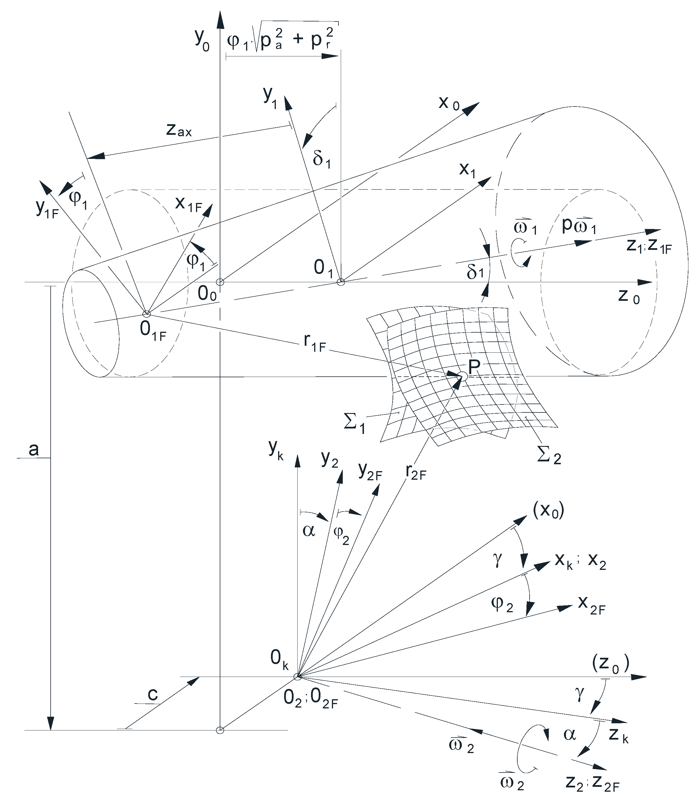
Figure 2.
The schematic arrangement of the machining of the conical worm on a traditional thread grinding machine [34].
Figure 2.
The schematic arrangement of the machining of the conical worm on a traditional thread grinding machine [34].
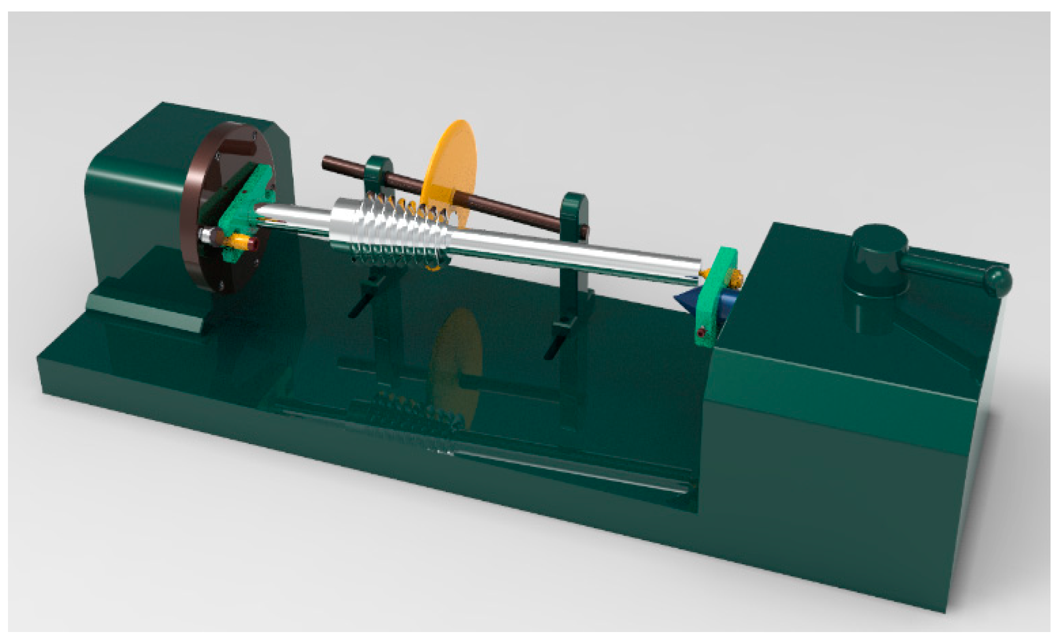
Figure 3.
The relationship of the applied coordinate systems to each other for a more general study of the manufacturing theory of the elements of bevel and cylindrical worm gear pairs in the improved constructive geometric model.
Figure 3.
The relationship of the applied coordinate systems to each other for a more general study of the manufacturing theory of the elements of bevel and cylindrical worm gear pairs in the improved constructive geometric model.
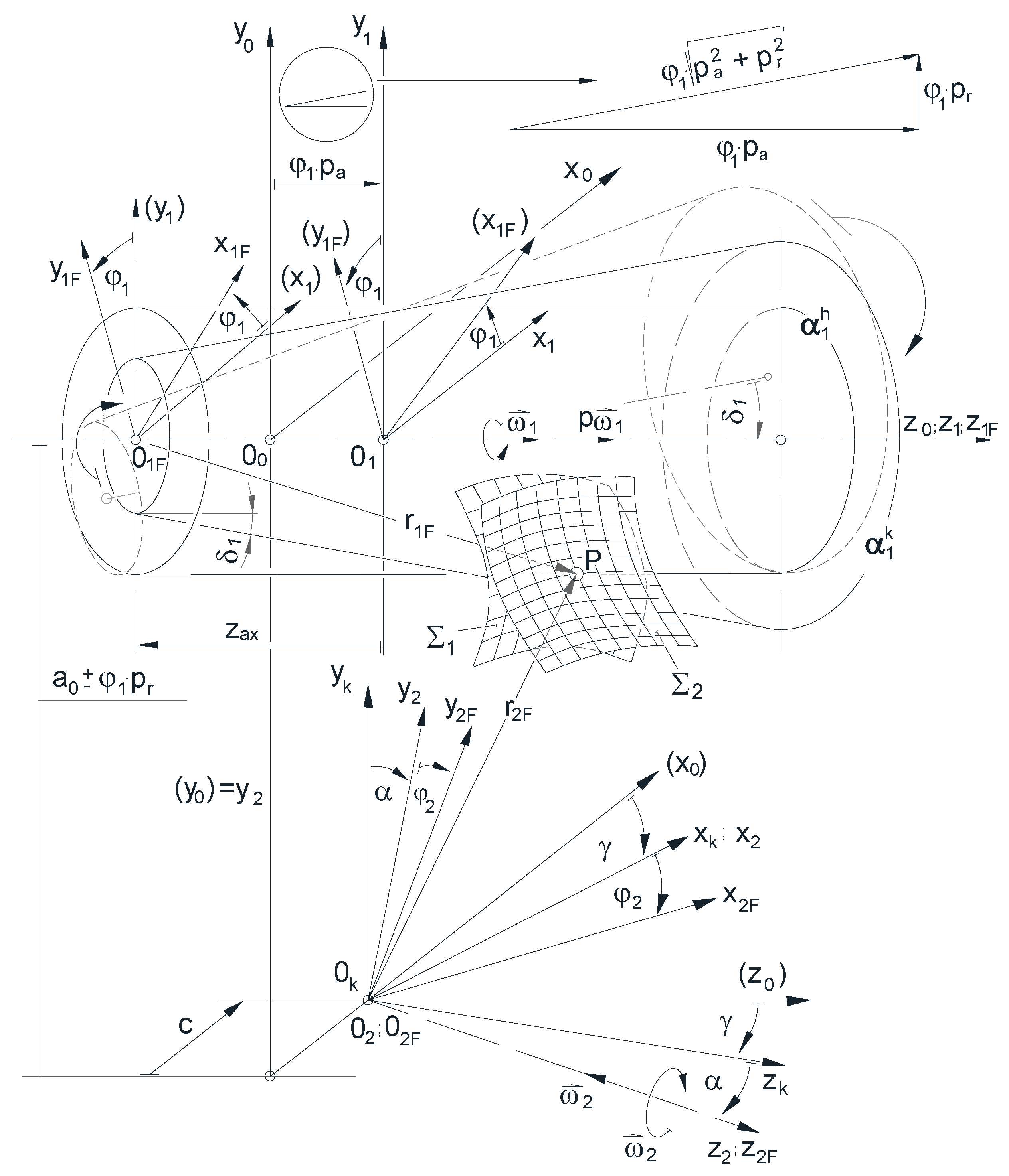
Figure 4.
The sections of the reference cylinder and the reference cone in the coordinate plane [yz], in case of the cylinder vertex Mh∞ is infinity distance on the z1F and vertex Mk is positioned at the origin O1F.
Figure 4.
The sections of the reference cylinder and the reference cone in the coordinate plane [yz], in case of the cylinder vertex Mh∞ is infinity distance on the z1F and vertex Mk is positioned at the origin O1F.
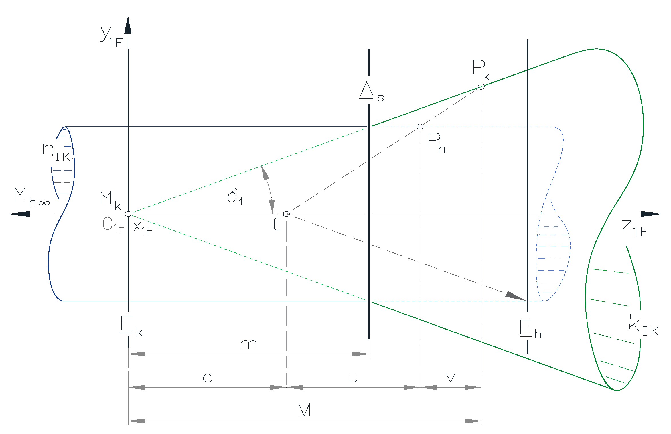
Figure 5.
The sections of the reference cylinder and the reference cone in the coordinate plane [yz], in case of the cylinder vertex Mh∞ is infinity distance on the z1F and vertex Mk is positioned at the origin O1F.
Figure 5.
The sections of the reference cylinder and the reference cone in the coordinate plane [yz], in case of the cylinder vertex Mh∞ is infinity distance on the z1F and vertex Mk is positioned at the origin O1F.
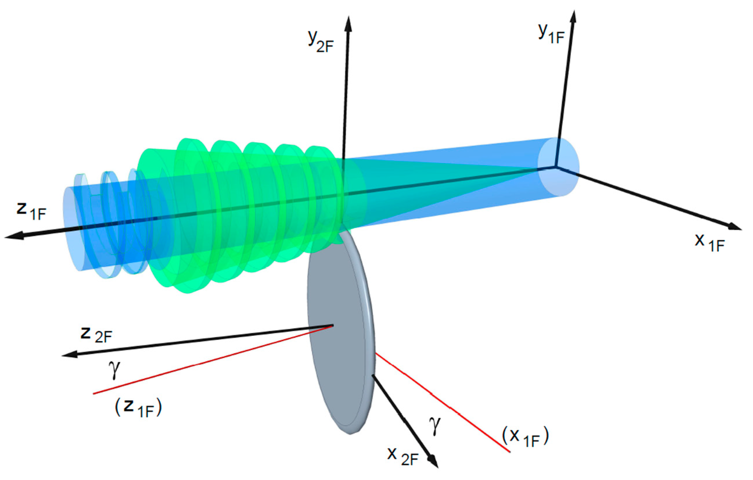

Table 1.
The corresponded points between the reference cylinder and the reference cone.
| Cylinder points | Cone points | |
|---|---|---|
Table 2.
Equations for the λI unknows and solutions.
| Equations | Solutions | |
|---|---|---|
Table 3.
Equations for the I unknows and solutions.
| Title 1 | Title 2 | Title 3 |
|---|---|---|
Disclaimer/Publisher’s Note: The statements, opinions and data contained in all publications are solely those of the individual author(s) and contributor(s) and not of MDPI and/or the editor(s). MDPI and/or the editor(s) disclaim responsibility for any injury to people or property resulting from any ideas, methods, instructions or products referred to in the content. |
© 2024 by the authors. Licensee MDPI, Basel, Switzerland. This article is an open access article distributed under the terms and conditions of the Creative Commons Attribution (CC BY) license (http://creativecommons.org/licenses/by/4.0/).
Copyright: This open access article is published under a Creative Commons CC BY 4.0 license, which permit the free download, distribution, and reuse, provided that the author and preprint are cited in any reuse.


